1
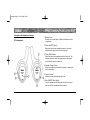
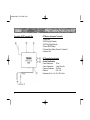
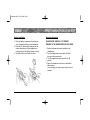
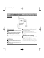
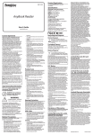
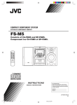
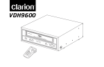
FinalManual.qxd 2/1/01 9:49 AM Page 1
AUTOMOTIVE RF STEREO
HEADPHONE SYSTEM
OWNER’S MANUAL
INSTALLATION GUIDE
FinalManual.qxd 2/1/01 9:49 AM Page 2
FinalManual.qxd 2/1/01 9:49 AM Page 1
WARNING!
THE CLARION WH105 RF HEADPHONES ARE DESIGNED
FOR LISTENING TO VIDEO OR AUDIO SOURCES FOR REAR
SEAT PASSENGERS ONLY.
If you do not have the required knowledge and experience to successfully complete the installation, we strongly recommend consulting an authorized Clarion dealer about professional
installation options.
TABLE OF CONTENTS
THIS PRODUCT IS NOT INTENDED FOR USE BY THE DRIVER
WHILE THE VEHICLE IS IN MOTION SINCE SUCH USE MAY
DISTRACT THE DRIVER OR INTERFERE WITH THE DRIVER'S
SAFE OPERATION OF THE VEHICLE AND MAY RESULT IN
SERIOUS INJURY OR DEATH. SUCH USE MAY ALSO VIOLATE STATE LAW.
CLARION DISCLAIMS ANY LIABILITY FOR ANY BODILY
INJURY, INCLUDING FATALITIES, OR PROPERTY DAMAGE
THAT MAY RESULT FROM ANY IMPROPER OR UNINTENDED
USES OF THIS PRODUCT.
ABOUT INSTALLATION
Installation of mobile audio and video components requires experience with a variety of mechanical and electrical procedures.
Even though this manual provides general installation and operation instructions for your new Clarion WH105 RF Headphones, it
does not show the exact installation methods for your particular
vehicle.
Introduction . . . . . . . . . . . . . . . . . . . . . . . . . . . . . . . . .
Description of Headphone Controls . . . . . . . . . . . . . .
Description of RF Transmitter Box . . . . . . . . . . . . . . .
RF Transmitter Box Specifications . . . . . . . . . . . . . . .
Battery Installation . . . . . . . . . . . . . . . . . . . . . . . . . . .
Operation Description . . . . . . . . . . . . . . . . . . . . . . . . .
Installation . . . . . . . . . . . . . . . . . . . . . . . . . . . . . . . . . .
Wiring Description . . . . . . . . . . . . . . . . . . . . . . . . . . . .
Mounting the RF Transmitter Box . . . . . . . . . . . . . . . .
Mounting the Antenna . . . . . . . . . . . . . . . . . . . . . . . . .
Testing the Unit . . . . . . . . . . . . . . . . . . . . . . . . . . . . . .
FCC Statement . . . . . . . . . . . . . . . . . . . . . . . . . . . . . .
.
.
.
.
.
.
.
.
.
.
.
.
.
.
.
.
.
.
.
.
.
.
.
.
.
.
.
.
.
.
.
.
.
.
.
.
.2
.3
.4
.4
.5
.5
.6
.7
.7
.7
.7
.8
1
FinalManual.qxd 2/1/01 9:49 AM Page 2
Introduction
The Clarion WH105 is a full-featured, high-tech Wireless
Automotive RF Stereo Headphone System specifically created for the mobile environment. The WH105 frees you
from the tangle of headphone wires and lets you enjoy
music or TV audio without the clutter of cables. To ensure
the best performance of your system, please read this
manual carefully.
Special Features
Automatic Level Control prevents
input signal over loading.
Uses RF transmission
Adjustable Headphone Band
Power Indicator LED
Auto ON/OFF Micro Switch
Independent Volume Controls
Additional Headphones
About The Manual And Warranty
The Clarion WH105 allows users to take full advantage of
the benefits of RF audio transmission and its ability to
operate multiple headphones from one single transmitter.
There is no need for Y-adapters, complex installation, or
concerns over electrical overload. Additional headphones,
WH105H, are available through your local Clarion Audio
Dealer.
To start enjoying your new Clarion WH105 system, please
read all remaining instructions listed in this manual. Keep
all instructions for future reference.
2
This product is covered by a limited warranty (see the
enclosed warranty card). Save the sales receipt to protect your purchase and aid in warranty service.
FinalManual.qxd 2/1/01 9:49 AM Page 3
Description Of Headphone Controls
RF Headphones
1. Battery Cover
Remove the cover and place 2 Alkaline AAA batteries in the
compartment
2. Power ON/OFF Switch
Main power switch turns headphone power off to prevent
accidental micro switch activation during storage.
3. Power LED Indicator
When illuminated, the headphones are fully functional. The
indicator will turn off when the headphones are removed or
when the power switch is turned off.
4. Variable Tuning Control
Allows user to adjust the noise and frequency for the desired
audio source signal.
5. Volume Control
Allows user to set individual listening levels.
6. Auto ON/OFF Micro Switch
Turns the headphones ON when placed on the user's head
and turns OFF the headphones when removed.
3
FinalManual.qxd 2/1/01 9:49 AM Page 4
Description Of RF Transmitter Box
RF Wireless Automotive Transmitter
1.Power Input
2.RCA Plug (Left Channel)
3.RCA Plug (Right Channel)
4.Power ON/OFF Switch
5.Channel Select Switch (Channel 1, Channel 2)
6.Antenna Cord
RF Transmitter Specifications
General Specifications
Power Requirement:
Power Consumption:
Frequency Response:
Distortion:
Dimensions (W x L x H):
4
12 Vdc
1 watt, Power On
35-12KHz
0.8%-1.5%
62 x 103 x 26mm
FinalManual.qxd 2/1/01 9:49 AM Page 5
Battery Installation
Operation Description
1. Open the battery compartment by sliding the
cover towards the bottom of the Headphone.
2. Place two (2) alkaline AAA batteries into the
battery compartment of the Headphone(s),
making sure that the battery polarity is correct.
3. Snap the battery cover back into place.
PLEASE READ CAREFULLY TO PREVENT
DAMAGE TO THE HEADPHONES OR YOUR EARS.
1. Be sure batteries are properly installed in the
Headphones.
2. Turn the Headphone volume nearly off before
turning on the power switch.
3. Turn the Headphone power switch to the ON
position.
4. Adjust the Headphone volume to a comfortable
listening level.
(You can adjust the audio source volume louder if
needed).
5
FinalManual.qxd 2/1/01 9:49 AM Page 6
INSTALLATION
Precautions
Do not allow liquids or foreign objects to enter the WH105 RF
Transmitter or Headphones.
If any unit should become wet, turn off all power and let your
authorzied Clarion Dealer clean or service the equipment.
DO NOT ATTEMPT TO OPEN OR SERVICE THE RF
TRANSMITTER OR HEADPHONES. THE INTERNAL
PARTS ARE NOT USER-SERVICEABLE. DOING SO
WILL VOID THE WARRANTY.
Do not drop or excessively jar the WH105 headpones.
Do not use liquid cleaners on any surfaces. Only use a soft
(cotton or other non-static) cloth to wipe off fingerprints.
Do not subject the unit to direct sunlight or an extremely hot
environment (e.g., closed windows on a hot summer day,
direct path of heater vent, etc.)
Avoid using the products under the following contitions:
- After extended parking on an extremely hot or cold day
- Near strong magnetic fields
- In an environment with excessive humidity, dust, or
vibration (e.g., off-road travel, etc.)
6
Wiring
This unit operates on an automotive 12-volt negative ground
power source and requires additional mobile audio and video
components for proper operation.
Before installation, disconnect the (-) negative lead from the
vehcile's battery.
Attach the RF Transmitter to a location near your A/V Source
with the provided adhesive tape.
Connect the power and ground wire connectors to the 12Vdc
input. Connect black (-) wire to ground of the vehicle, and
red (+) wire to an accessory 12Vdc power source.
Connect the audio input to a low-level output. With this
connection, only the volume control on the earphones needs
to be adjusted to control volume level.
FinalManual.qxd 2/1/01 9:49 AM Page 7
Wiring Description
Mounting The Transmitter
The transmitter box can be mounted virtually anywhere in the
vehicle.
For optimum useage, mount away from vehicle computers,
vehicle wire harnesses or any other sources of noise.
Mount the unit securely with the provided adhesive tape so
that the unit doesn't move around when the vehicle is in
motion.
Mounting The Antenna
Mount the antenna as straight and as high in the vehicle as
possible.
Do not ground the antenna wire or allow the bare tip of the
antenna to touch metal.
Do not cut the antenna or alter its length in any way, as it will
change the operating frequency.
Do not wrap the antenna around the transmitter box.
Do not coil the antenna along any existing vehicle harnesses.
Testing The Unit
Make sure the unit is switched to on when testing.
Test for noise and frequency by switching from Channel 1 or 2
for the desired audio source signal.
NOTE: Remove headphones and lower the volume before
switching between channels. The signal on one channel may
be louder than the other, resulting in possible hearing damage.
7
FinalManual.qxd 2/1/01 9:49 AM Page 8
FCC Statement
This equipment has been tested and found to comply with the limits for a Class B digital
device, pursuant to Part 15 of the FCC Rules. These limits are designed to provide
reasonable protection against harmful interference in an automotive installation. This
equipment generates, uses, and can radiate radio frequency energy and, if not installed and
used in accordance with the instructions, may cause harmful interference to radio communications. However, there is no guarantee that interference will not occur in a particular
installation.
If this equipment does cause harmful interference to radio or television reception, which
can be verified by turning the unit off and on, the user is encouraged to consult the dealer
or an experienced radio/television technician for help.
8
FinalManual.qxd 2/1/01 9:49 AM Page 9
FinalManual.qxd 2/1/01 9:49 AM Page 10
661 W. Redondo Beach Blvd.
Gardena, CA 90247
1-800-G0-CLARION
www.clarion-usa.com
©2000 Clarion Sales Corporation
Rev. 0 (09/00)