1
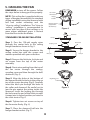
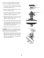
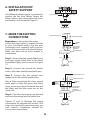
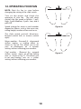
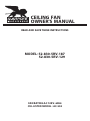
CEILING FAN
OWNER'S MANUAL
READ AND SAVE THESE INSTRUCTIONS
MODEL: 52-830-5RV-187
52-830-5RV-129
FAN RATING AC 120V. 60Hz
CUL LISTED MODEL : AC-552
1. TOOLS AND MATERIALS
REQUIRED
Philips screw driver
Blade screw driver
11 mm wrench
Step ladder
Wire cutters
2. PACKAGE CONTENTS
Unpack your fan and check the contents.
You should have the following items;
a.
b.
c.
d.
e.
f.
g.
h.
i.
j.
k.
b
c
Set of blades assembly (5)
Hanger bracket
Canopy
Downrod
Coupling cover
Fan motor assembly
Mounting plate
Set of blades bracket (5)
Switch housing
Pull chain and fob
Package hardware
1) Mounting hardware :
screws(2), lock washers(2),
star washers(2), wire nuts(3)
wood screws(2), washers(2)
2) Blade attachment hardware:
screws(16)
3) Blade arm hardware:
screws with lock washers (11)
4) Safety cable hardware:
wood screw, lock washer,
metal washer
5) Balance Kit
a
d
e
f
g
h
i
j
k
1
3. SAFETY RULES
1. To reduce the risk of electric shock,
insure electricity has been turned off
at the circuit breaker or fuse box
before beginning.
7. Do not operate reversing switch while
fan blades are in motion. Fan must be
turned off and blades stopped before
reversing blade direction.
2. All wiring must be in accordance with
the National Electrical Code and local
electrical codes. Electrical installation
should be performed by a qualified
licensed electrician.
8. Avoid placing objects in the path of the
blades.
9. To avoid personal injury or damage to
the fan and other items, be cautious
when working around or cleaning the
fan.
3. WARNING: To reduce the risk of
electrical shock and fire, do not use
this fan with any solid-state fan speed
control device.
10. Do not use water or detergents when
cleaning the fan or fan blades. A dry
dust cloth or lightly dampened cloth
will be suitable for most cleaning.
4. WARNING: To reduce the risk of
personal injury, use only the two steel
screws (and lock washers) provided
with the outlet box for mounting to
the outlet box. Most outlet boxes
commonly used for the support of
lighting fixtures are not acceptable for
fan support and may need to be
replaced, consult a qualified electrician
if in doubt.
11. After marking electrical connections,
spliced conductors should be turned
upward and pushed carefully up into
outlet box. The wires should be spread
apart with the grounded conductor
and the equipment-grounding
conductor on one side of the outlet
box.
12. Electrical diagrams are reference only.
Light kit that are not packed with the
fan must be CUL Listed and marked
suitable for use with the model fan you
are installing. Switches must be CUL
General Use Switches. Refer to the
Instructions packaged with the light
kits and switches for proper assembly.
WARNING
TO REDUCE THE RISK OF FIRE,
ELECTRIC SHOCK OR PERSONAL
INJURY, MOUNT FAN TO OUTLET BOX
MARKED "ACCEPTABLE FOR FAN
SUPPORT".
5. The outlet box and support structure
must be securely mounted and
capable of reliably supporting a
minimum of 50 pounds. Use only CUL
Listed outlet boxes marked "FOR FAN
SUPPORT".
6.
WARNING
TO REDUCE THE RISK OF PERSONAL
INJURY, DO NOT BEND THE BLADE
BRACKETS (ALSO REFERRED TO AS
FLANGES) DURING ASSEMBLY OR
AFTER INSTALLATION. DO NOT
INSERT OBJECTS IN THE PATH OF THE
BLADES.
The fan must be mounted with a
minimum of 7 feet clearance from the
trailing edge of the blades to the floor.
2
4. MOUNTING OPTIONS
If there isn't an existing CUL listed
mounting box, then read the following
instructions. Disconnect the power by
removing fuses or turning off circuit
breakers.
Outlet box
Secure the outlet box directly to the
building structure. Use appropriate
fasteners and building materials. The
outlet box and its support must be able to
fully support the moving weight of the fan
(at least 50 lbs). Do not use plastic outlet
boxes.
Figure 1
Figures 1, 2 and 3 are examples of different
ways to mount the outlet box.
Note: You may need a longer downrod to
maintain proper blade clearance when
installing on a steep, sloped ceiling. (Fig. 3)
Outlet box
Figure 2
To hang your fan where there is an existing
fixture but no ceiling joist, you may need
an installation hanger bar as shown in
Figure 4.
Provide strong
support
Recessed
outlet box
Ceiling
mounting
plate
Figure 3
Outlet box
Figure 4
3
5. HANGING THE FAN
REMEMBER to turn off the power. Follow
the steps below to hang your fan properly.
CUL Listed
electrical box
NOTE: This ceiling fan is supplied with two
types of hanging assemblies; the standard
ceiling installation using the downrod with
ball and socket mounting and the
"close-to-ceiling" installation. The "close-to
-ceiling" installation is recommended in
rooms with less than 8-feet ceilings or in
areas where additional space is desired
from the floor to the fan blades.
Hanger
bracket
Tab
Mounting screws
(supplied with
electrical box)
Figure 5
Downrod
STANDARD CEILING INSTALLATION
Canopy
Step 1. Pass the 120-volt supply wires
through the center hole in the ceiling
hanger bracket as shown in Fig. 5.
Set screws
Coupling cover
Step 2. Secure the hanger bracket to the
ceiling outlet box with the screws and
washers provided with your outlet box.
Hitch pin
Step 3. Remove the hitch pin, lock pin and
set screws from the top of the motor
assembly.
Lock pin
Figure 6
Step 4. Route wires exiting from the top of
the fan motor through the canopy,
coupling cover and then through the ball/
downrod. (Fig. 6)
Step 5. Align the holes at the bottom of
the downrod with the holes in the collar on
top of the motor housing (Fig.6). Carefully
insert the hitch pin through the holes in
the collar and downrod. Be careful not to
jam the pin against the wiring inside the
downrod. Insert the locking pin through
the hole near the end of the hitch pin until
it snaps into its locked position, as noted in
the circle inset of Fig. 6.
Registration slot
Figure 7
Step 6. Tighten two set screws on top of
the fan motor firmly. (Fig. 6)
Step 7. Place the downrod ball into the
hanger bracket socket. (Fig. 7)
4
CLOSE-TO-CEILING INSTALLATION
1. Pass the 120-volt supply wires through
the center hole in the ceiling hanger
bracket as shown in Fig. 5.
Canopy
Figure 8
2. Remove the decorative canopy cover
from the canopy. (Fig. 8)
3. Secure the hanger bracket to the ceiling
outlet box with the screws and washers
provided with your outlet box.
Decorative canopy
cover
Screw and lockwasher
(3 of 6 places)
Canopy
4. Remove three of the six screws and lock
washers (every other one) from the
collar of top motor. (Fig. 9)
Collar
5. Place the ceiling canopy over the collar
at the top of the motor. Align the
mounting holes with the holes in the
motor and fasten using the screws and
lock washers provided. (Fig. 9)
Figure 9
6. Tighten the mounting screws securely.
Hook
WARNING: Failure to completely tighten
the three screws in step 5 could result in
fan loosening and possibly falling.
7. Hang the fan on the hook of the hanger
bracket. Be certain that the canopy is
fully locked into hook as shown in Fig.
10. This will allow you to make the
electrical connections.
Figure 10
5
6. INSTALLATION OF
SAFETY SUPPORT
An additional safety support is provided to
prevent the fan from falling. Secure the
safety cable to the ceiling joist with screw
and washer, as illustrated in Figure 11.
Safety cable
Hanger bracket
Figure 11
7. MAKE THE ELECTRIC
CONNECTIONS
POWER LINES 120V
Remember to disconnect the power.
Follow the steps below to connect the fan
to your household wiring. Use the wire
connecting nuts supplied with your fan.
Secure the connectors with electrical tape.
Make sure there are no loose strands or
connections.
WH
BLK
GREEN GROUND
GRN
WH
BLUE
BLK
WIRING
BOX
GROUND TO
MOUNTING
BRACKET
OR DOWNROD
FAN
Step 1. Connect the fan supply (black) wire
and light supply (blue) wire to the black
household supply wire as shown in Figure
12.
BLUE
WH
BLK
WH
LIGHT
Figure 12
Step 2. Connect the neutral fan (white)
wire to the white neutral household wire.
BLK
Step 4. After connecting the wires, spread
them apart so that the green and white
wires are on one side of the outlet box and
the black and the blue wires are on the
other side.
WH
POWER LINES 120V
Step 3. Connect the fan ground wire
(green) to the household ground wire.
GREEN GROUND
WIRING
BOX
Step 5. Turn the connecting nuts upward
and push the wiring into the outlet box.
GROUND TO
MOUNTING
BRACKET
OR DOWNROD
FAN
WH
BLK
BLUE
LIGHT
SWITCH
BLUE
WH
BLK
WH
LIGHT
Figures 13 and 14 illustrate the wiring
connections for optional wall control. (The
wire color out of wall control may vary, see
wall control's installation manual for
correct wire connections.)
Figure 13
6
NOTE: LIGHT KITS ARE AVAILABLE AT YOU
SAVOY HOUSE RETAILER. THE FAN IS
ALREADY WIRED TO SUPPORT THE LIGHT
KIT OPTION.
WIRING
BOX
FAN
BLUE
BLK
WARNING: TO REDUCE THE RISK OF FIRE,
ELECTRIC SHOCK, OR OTHER PERSONAL
INJURY. MOUNT FAN ONLY ON AN OUTLET
BOX OR SUPPORTING SYSTEM MARKED
ACCEPTABLE FOR FAN SUPPORT.
GREEN
GROUND
GROUND TO
MOUNTING
BRACKET
OR DOWNROD
WH
LIGHT
WH
BLK
POWER LINES 120V
FAN
BLUE
WH
BLK
WH
LIGHT
Figure 14
Outlet box
Screws
8. FINISHING THE
INSTALLATION
Hanger
bracket
STANDARD CEILING INSTALLATION
Ceiling canopy
Slide canopy up to the ceiling as shown in
Figure 15. Make sure you place the wires
safely into the outlet box. Secure the
canopy to the hanger bracket with the four
screws with your fan.
CLOSE-TO-CEILING INSTALLATION
Remove the fan from the hook on the
hanger bracket. Secure the canopy to the
hanger bracket as shown in Figure 16 with
four screws included with your fan.
Figure 15
Outlet box
Screws
Hanger
bracket
Ceiling canopy
Figure 16
7
9. ATTACHING THE FAN
BLADES
Caution: Remove 5 rubber packing
mounts and discard before installation.
Step 1. Attach the blade to the blade
bracket using the screws and rubber
washers as shown in Figure 17. Start screw
into bracket. Repeat for the two
remaining screws.
Screws
Blade
Rubber
washers
Step 2. Tighten each screw. Make sure
the blade is straight.
Screws
Blade bracket
Step 3. Fasten blade assembly to motor
using the screws supplied. (Fig. 17)
Figure 17
10. INSTALLATING THE
MOUNTING PLATE
Step 1. Remove the 1 of 3 screws from the
mounting ring and loosen the other 2
screws. (Do not remove)
Step 2. Place the key holes on the
mounting plate over the 2 screws
previously loosened from the mounting
ring, turn mounting plate until it locks in
place at the narrow section of the key
holes. Secure by tightening the 2 screws
previously loosened and the one
previously removed. (Fig. 18)
Mounting ring
Screws
Figure 18
8
Mounting
plate
11. INSTALLING THE
SWITCH HOUSING
NOTE: Before starting installation,
disconnect the power by turning off the
circuit breaker or removing the fuse at
fuse box. Turning power off using the fan
switch is not sufficient to prevent electric
shock.
Step 1. Remove the screws from the
mounting plate under the fan motor.
Step 2. While holding the switch housing
under your fan, snap together the wire
connection plug. (Figure 19)
Step 3. Raise the switch housing to the
mounting plate until the holes in switch
housing and mounting plate line up.
Reinsert screws to secure in place. (Figure
19)
Connection plug
Switch housing
Screws
Figure 19
9
Mounting plate
12. OPERATING YOUR FAN
NOTE: Wait for fan to stop before
changing the setting of the slide switch.
Turn on the power and check the
operation of your fan. The pull chain
controls the fan speed as follows: 1 pullHigh, 2 pulls-Medium, 3 pulls- Low, and 4
pulls-Off.
Figure 20
Speed settings for warm or cool weather
depend on factors such as the room size,
ceiling height, number of fans and so on.
The slide switch controls directions:
forward (switch left) or reverse (switch
right)
Warm weather - (Forward) A downward
airflow creates a cooling effect as
shown in Fig. 20. This allows you to set
your air conditioner on a warmer
setting without affecting your comfort.
Cool weather - (Reverse) An upward
airflow moves warm air off the ceiling
area as shown in Fig. 21. This allows you
to set your heating unit on a cooler
setting without affecting your comfort.
Figure 21
10
13. TROUBLESHOOTING
Problem
Solution
Fan will not start. 1.Check circuit fuses or breakers.
2. Check line wire connections to the fan and switch wire connections
in the switch housing.
CAUTION: Make sure main power is off.
Fan sounds
noisy.
1. Make sure all motor housing screws are snug.
2. Make sure the screws that attach the fan blade bracket to the motor
hub is tight.
3. Make sure wire nut connections are not rubbing against each other
or the interior wall of the switch housing.
CAUTION: Make sure main power is off.
4. Allow a 24-hour "breaking-in" period. Most noise associated with a
new fan disappear during this time.
5. If using an optional light kit, make sure the screws securing the
glassware are tight. Check that light bulb is also secure.
6. Some fan motors are sensitive to signals from solid-state variable
speed controls. If you have installed this type of control, choose and
install another type of control.
7. Make sure the upper canopy is a short distance from the ceiling. It
should not touch the ceiling.
11