1
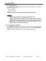
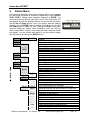
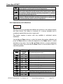
User Manual Software Version 1.60 Revised 07/2005 Power Spot 575IE™ ©Elation Professionals® Los Angeles, Ca. - wwww.ElationLighting.com - Page 2 Power Spot 575IE™ Table of Contents Introduction..........................................................................................................................5 Unpacking ......................................................................................................................5 Customer Support .......................................................................................................5 Discharge Lamp Precautions .......................................................................................6 Safety Instructions ............................................................................................................7 1 Fixture Layout......................................................................................................................8 2 Preparation and Installation ......................................................................................... 11 2.1 Mounting ..................................................................................................................... 11 2.1.1 Clamps............................................................................................................ 11 2.1.2 Mounting Plate................................................................................................ 12 2.2 Rigging the Power Spot 575IE™............................................................................ 12 2.3 Connections................................................................................................................ 13 2.3.1 Power Supply................................................................................................ 13 2.3.2 DMX-512 Pin Configuration.......................................................................... 13 2.4 DMX-512.................................................................................................................... 13 2.5 Data Cable Requirements........................................................................................ 13 2.6 Special Note............................................................................................................... 13 2.7 Line Termination ......................................................................................................... 13 2.8 MX Pin Conversion ................................................................................................... 13 2.9 Fuse Requirements ................................................................................................... 13 2.10 Transporting & Handling ............................................................................................ 13 3 Menu Field .......................................................................................................................... 16 3.1 Setting the DMX - Address (D001)....................................................................... 18 3.2 Test Menu (TEST).................................................................................................... 18 3.3 Lamp On/Off (LAMP) .............................................................................................. 18 3.4 Reset (RESE) .......................................................................................................... 18 3.5 Running Time (lamp/unit) (TIME)............................................................................. 18 3.6 Invert Pan Movement (RPAN) ............................................................................... 19 3.7 Invert Tilt Movement (RTLT) ................................................................................... 19 3.8 DMX Mode ................................................................................................................ 19 3.9 Special Functions (SPEC) ...................................................................................... 19 3.9.1 Manual Drive (MANU).................................................................................. 20 3.9.2 Lamp On (automatic) (LAAU)...................................................................... 20 3.9.3 Lamp Off (via DMX)...................................................................................... 21 3.9.4 DMX Input (DLOF) ...................................................................................... 22 3.9.5 LED Display (DISP).................................................................................... 21 ©Elation Professionals® Los Angeles, Ca. - wwww.ElationLighting.com - Page 3 Power Spot 575IE™ 3.9.6 Fixture Temperature (TEMP)....................................................................... 22 3.9.7 Fan Control (FANS) .................................................................................... 22 3.9.8 Adjustments and Calibrations (ADJU) ...................................................... 23 3.9.9 Default Settings (DFSE).............................................................................. 24 3.9.10Feedback (FEED) ........................................................................................ 24 3.9.11Fault Corrections (EFLD) ............................................................................ 24 3.10 Error and Information Messages............................................................................... 24 4 Operating Modes.............................................................................................................. 25 4.1 Universal DMX Control ............................................................................................. 27 4.2 Stand Alone (Sound Active) .................................................................................... 27 4.3 Master-Slave.............................................................................................................. 28 5 DMX Channel Selection (DMX Protocol)..................................................................... 29 6 Lamp Change .................................................................................................................... 33 6.1 Safety Regulations .................................................................................................... 34 6.2 Realize the Lamp Change........................................................................................ 34 7 Fuse Replacement........................................................................................................... 35 8 Change a Gobo................................................................................................................. 37 8.1.1 Safety Regulations......................................................................................... 37 8.1.2 Realize the Gobo Change............................................................................ 37 9 Maintenance and Cleaning the Power Spot 575IE™............................................ 39 9.1 Safety Regulations .................................................................................................... 39 9.2 Circumference and Interval........................................................................................ 39 9.3 Cleaning the Optical System.................................................................................... 40 10 Technical Specification.................................................................................................. 40 11 Warranty.............................................................................................................................. 41 12 Dimensions........................................................................................................................ 43 13 Index .................................................................................................................................... 44 ©Elation Professionals® Los Angeles, Ca. - wwww.ElationLighting.com - Page 4 Power Spot 575IE™ INTRODUCTION: Congratulations, you have just purchased one of the most innovative and reliable lighting fixtures on the market today! The Power Spot 575IE™, has been designed to perform reliably for years when the guidelines in this booklet are followed. Please read and understand the instructions in this manual carefully and thoroughly before attempting to operate this unit. These instructions contain important information regarding safety during use and maintenance. UNPACKING: Thank you for purchasing the Power Spot 575IE™ by Elation Professional®. Every Power Spot 575IE™ has been thoroughly tested and has been shipped in perfect operating condition. Carefully check the shipping carton for damage that may have occurred during shipping. If the carton appears to be damaged, carefully inspect your unit for damage and be sure all accessories necessary to operate the unit have arrived intact. In the event damage has been found or parts are missing, please contact our customer support team for further instructions. Please do not return this unit to your dealer without first contacting customer support at the number listed below. CUSTOMER SUPPORT: Elation Professional® provides a customer support line, to provide set up help and to answer any question should you encounter problems during your set up or initial operation. You may also visit us on the web at www.elationlighting.com for any comments or suggestions. For service related issue please contact Elation Professional®. Service Hours are Monday through Friday 9:00 a.m. to 5:00 p.m. Pacific Standard Time. Voice: Fax: E-mail: Forum: (323) 582-3322 (323) 582-3108 [email protected] www.ElationLighting.com/forum/ Warning! To prevent or reduce the risk of electrical shock or fire, do not expose this unit to rain or moisture. Caution! There are no user serviceable parts inside this unit. Do not attempt any repairs yourself, doing so will void your manufactures warranty. Please do not discard the shipping carton in the trash. Please recycle whenever possible. WARRANTY REGISTRATION: The Power Spot 575IE™ carries a two year (730 days) limited warranty. Please fill out the enclosed warranty card to validate your purchase. All returned service items whether under warranty or not, must be freight pre-paid and accompany a return authorization (R.A.) number. The R.A. number must be clearly written on the outside of the return package. A brief description of the problem as well as the R.A. number must also be written down on a piece of paper and included in the shipping container. ©Elation Professionals® Los Angeles, Ca. - wwww.ElationLighting.com - Page 5 Power Spot 575IE™ If the unit is under warranty, you must provide a copy of your proof of purchase invoice. Items returned without a R.A. number clearly marked on the outside of the package will be refused and returned at cutomers exspence. You may obtain a R.A. number by contacting customer support at (323) 582-3322. DISC HARGE LAMP WARNING: This fixture is fitted with a discharge lamp, which is highly susceptible to damage if improperly handled. Never touch the lamp with your bare hands, as the oil from your hands will shorten lamp life. Also, never move the fixture until the lamps have had ample time to cool. Remember, lamps are not covered under warranty conditions. This fixture emits intense UV radiation, which is harmful to the eyes and skin. The intense luminance of the lamp can cause severe damage to the retina. Never operate this fixture with the protective covers removed, these covers have been specially designed to shield against UV radiation. Epileptic Warning: Those suffering from epilepsy should avoid looking directly into the lamp at all times. Avoid switching the fixture on and off repeatedly in short intervals, as this will reduce lamp life and intensity. To achieve the intensity associated with discharge lamps, these lamps use a gas sealed in a high-pressure environment to emit a brilliant output. Due to the high pressure involved with the construction of the lamp, the lamp may explode during prolonged extensive use. This risk is increased with age; added care is encouraged when dealing with older lamps. Thus, lamp should always be replaced at the end of their recommended duty cycle. Extreme caution should be used when operated this or any fixture fitted with a gas discharge lamp. Never open this fixture while in use! During the initial operation of this fixture, a light smoke or smell may emit from the interior of the fixture. This is a normal process and is caused by excess paint in the interior of the casing burning off from the heat associated with the lamp. ©Elation Professionals® Los Angeles, Ca. - wwww.ElationLighting.com - Page 6 Power Spot 575IE™ Safety Instructions The Power Spot 575IE™ is an extremely sophisticated piece of electronic equipment. To guarantee a smooth operation, it is important to follow the guidelines in this manual. The manufacturer of this device will not accept responsibility for damages resulting from the misuse of this fixture due to the disregard of the information printed in this manual. 1. Always be sure that the fan and the air inlets remain clean and are never blocked. Allow about 6” (15cm) between this fixture and other devices or a wall to allow for proper cooling. 2. Never touch the fixture during normal operation. This can cause severe personal injuries and/or damage to the fixture. 3. Be sure to unplug the POWER SPOT 575IE™ from the power outlet before performing any service related issues. 4. Lamp Replacement; Allow at least 30 minutes after disconnecting main power before you open the POWER SPOT 575IE™. To prevent personal injury, never touch the lamp if you are not absolutely sure it has cooled. 5. Never look directly into the lamp beam. You risk injury to your retina, which may induce blindness. 6. Be sure to track and record the lamp running time. The lamp should be changed at the end of the specified lamp life, regardless of lamp output. You may also have to change the lamp if it shows any deformations or damage. The same is with all glass components, color filters, lenses and mirrors. 7. For safe operation, follow the Installation guide described in chapter two of this manual. Operating the POWER SPOT 575IE™ without suited safety aids such as safety cables or clamps can increase the risk of damage and/or personal injury. 8. Installation should only be performed by qualified and certified personal. 9. When mounting this fixture, use only the original rigging parts included with this fixture. Any structural modification will void the original manufactures warranty and may increase the risk of damage and/or personal injury. 10. To reduce the risk of fire or shock, do not expose this unit to rain or moisture. 11. Do not attempt to operate this fixture if the power cord is frayed or damaged. Attention: Lasers of class 3R may injure your retina after a short residence time even without any optical instrument. Avoid any direct exposure of your eyes! ©Elation Professionals® Los Angeles, Ca. - wwww.ElationLighting.com - Page 7 Power Spot 575IE™ 1. Fixture Layout 1 1. Lens Assembly 2. DMX Input Jack 8 3. DMX Output Jack 4. Microphone Sensitivity Adjustment Knob 5. Firmware Connection 6. Internal Cooling Fan 7. Base 8. Retaining Arm 7 2 4 3 6 5 9 10 15 16 17 18 11 9. Lamp Fuse Holder 10. Electronics Fuse Holder 11. Powercon Connector 12. Power Switch 13. Carrying Handle 14. 4-Segment Menu Display 15. Mode Select Button 6 13 14 12 16. Enter Select Button 17. Down Select Button 18. Up Select Button ©Elation Professionals® Los Angeles, Ca. - wwww.ElationLighting.com - Page 8 Power Spot 575IE™ 1. Lens Assembly - This high quality lens is a fully focusing. Focus the lens b y manually turning the lens in a clockwise or counter-clockwise direction until the desired effect is achieved. 2. DMX Input Jack – This 3-Pin XLR jack is used to receive an incoming DMX signal. 3. DMX Output Jack – This 3-Pin XLR jack is used to send an outgoing DMX signal. For best results this jack should be terminated if it is the last fixture in a DMX daisychain (see termination on page 14). 4. Microphone Sensitivity Adjustment Knob – This knob is used to adjust the frequency sensitivity of the internal microphone when operating in “audio” mode. When the knob is turned counter-clockwise the unit is less sensitive to sound. When the knob is turned clockwise the unit is more sensitive sound. 5. Firmware Connection – This connection is designed to be used solely by an authorized technician to upgrade the operating software and to test the fixture. 6. Internal Cooling Fan – This fixture is equipped with two high-velocity variable speed fans mounted in the base to aid in the cooling process. These fans are designed to vary their velocity at different operating temperatures. When the fixture reaches a predetermined internal operating temperature the fans function at high speeds. The higher speeds provide better cooling associated with higher operating temperatures during long use. When the fixture is operating at a lower temperature the fans operate at low speed. Be sure to keep all vents clean, blocked cooling vents can shorten lamp life and reduce the fixtures reliability. For more information on the fan functions see page 23, section 3.9.7. 7. Base – The main base holds the majority of the electronics and logic boards. The base also provides a means to securely mount the fixture to the floor or ceiling. 8. Retaining Arm – These arm hold the head in place and provide a means of tilt movement. These arms also provide a conduit for all the electronics traveling from the base to the head. 9. Lamp Fuse Holder – This housing holds a 8A/250V GMA fuse. Never defeat this fuse, this fuse is designed to protect the lamp in the event of severer power fluctuations. In the event of fuse failure, always be sure to replace this fuse with an exact match unless otherwise instructed by an authorized Elation technician. 10. Electronics Fuse Holder – This housing holds a 1A/250V GMA fuse. Never defeat this fuse, this fuse is designed to protect the electronics in the event of severer power fluctuations. In the event of fuse failure, always be sure to replace this fuse with an exact match unless otherwise instructed by an authorized Elation technician. 11. Powercon Connector – This power jack is designed to be used only with the Neutrik Powercon adapter included with your fixture. This jack provides main power to your fixture. ©Elation Professionals® Los Angeles, Ca. - wwww.ElationLighting.com - Page 9 Power Spot 575IE™ 12. Power Switch – The switch is used to control main power to fixture’s electronics. 13. Carrying Handle – The fixtures includes two built-in carrying handles. Be sure to always handle the fixture by the built-in carrying handles. Never lift or carry the fixture by the head or retaining arms as this could cause serious damage to the fixture and void your manufactures warranty. 14. 4-Segment Menu Display – This display details menu functions. 15. Mode Select Button – This button is used to access the fixture’s main system menu and on-board programming functions. 16. Enter Select Button – This button is used to select and confirm a menu function when working in the fixture’s operating system. 17. Down Select Button – This button is used to scroll backwards when navigating through the system menu. 18. Up Select Button - This button is used to scroll forward when navigating through the system menu. ©Elation Professionals® Los Angeles, Ca. - wwww.ElationLighting.com - Page 10 Power Spot 575IE™ 2. Preparation and Installation 2.1 Mounting The POWER SPOT 575IE™ is fully operational in two different mounting positions, hanging upside from a ceiling or set on a flat level surface. To avoid internal damage to the unit, never mount the unit on its side as illustrated below. Be sure this fixture is kept at least 0.5m away from any flammable materials (decoration etc.). Install a safety cable that can hold at least 10 times the weight of the fixture. Never use the carrying handles for secondary attachment. Refer to regulations BGV C1 (formerly VBG 70) and DIN VDE 0711-217 for proper installation in Europe To ensure proper installation, only qualified staff should attempt installation. 2.1.1 Clamps The POWER SPOT 575IE™ has been designed to hold multiple clamps to the bottom of the unit in several different orientations. Always use an appropriately rated clamp to mount this unit to truss. Refer to the printed instructions on the bottom of the fixture for proper clamp installation. a) Cam lock System: This system allows a quick and efficient means to secure a clamp to the unit. To attach a clamp to the unit, attach a clamp that is rated to handle the weight of the unit to your cam lock. After a clamp has been ©Elation Professionals® Los Angeles, Ca. - wwww.ElationLighting.com - Page 11 Power Spot 575IE™ attached to the cam lock, attach the cam locks to the designated position on the bottom of your unit. Lock the cam locks into position by turning the wing nuts 90°. 90° b) Be sure to always use two cam locks mounted to the bottom of unit to ensure safe truss mounting (each two opposite threads max. M10x20). 4x M10x20mm 4x Camlock 2.2 Secure the POWER SPOT 575IE™ Regardless of the rigging option you choose for your POWER SPOT 575IE™ always be sure to secure your fixture with a safety cable. The fixture provides a built-in rigging point for a safety cable on the underside of the fixture, be sure to use this point and never secure a safety cable to a carrying handle. ©Elation Professionals® Los Angeles, Ca. - wwww.ElationLighting.com - Page 12 Power Spot 575IE™ 2.3 Connections 2.3.1 Power supply Electronic ballast with: 90~260 Volts, 50~60 Hz, Grounded contact type plug – Neutrik Powercon Connected load 780W <=> 3.8A (blind current compensation). NOTE: The universal power supply will accept any voltage source as detailed above without any type of internal or user modifications. 2.3.2 DMX-512 3-Pin XLR Input/Output. [+] = Pin 3 / [-] = Pin 2 / [Ground] = Pin 1 DMX-512: DMX is short for Digital Multiplex. This is a universal protocol used by most lighting and controller manufactures as a form of communication between intelligent fixtures and controllers. A DMX controller sends DMX data instructions from the controller to the fixture. DMX data i s sent out as serial data that travels from fixture to fixture via the DATA “IN” and DATA “OUT” XLR terminals located on all DMX fixtures (most controllers only have a DATA “OUT” terminals). DMX Linking: DMX is a language allowing all makes and models of different manufactures to be linked together and operate from a single controller, as long as all fixtures and the controller are DMX compliant. To ensure proper DMX data transmission, when using several DMX fixtures try to use the shortest cable path possible. The order in which fixtures are connected in a DMX line does not influence the DMX addressing. For example; a fixture assigned a DMX address of 1 may be placed anywhere in a DMX line, at the beginning, at the end, or anywhere in the middle. Therefore, the first fixture controlled by the controller could be the last fixture in the chain. When a fixture is assigned a DMX address of 1, the DMX controller knows to send DATA assigned to address 1 to that fixture, no matter where it is located in the DMX chain. 2.4 Data C able (DMX C able) Requirements (For DMX and Master/Slave Operation): The POWER SPOT 575IE™ can be controlled via DMX-512 protocol. The POWER SPOT 575IE™ is a 16 channel DMX fixture. The DMX address is set electronically using the controls on the side panel of the fixture. Your fixture and your DMX controller require a standard 3-pin XLR connector for data input and data output (Figure Below). If you are making your own cables, be sure to use standard two ©Elation Professionals® Los Angeles, Ca. - wwww.ElationLighting.com - Page 13 Power Spot 575IE™ conductor shielded cable (This cable may be purchased at almost all professional sound and lighting stores). Your cables should be made with a male and female XLR connector on either end of the cable. Also remember that DMX cab le must b e daisy chained and can not b e sp lit. 2.5 Notice: Be sure to follow the above figure when making your own cables. Do not use the ground lug on the XLR connector. Do not connect the cable’s shield conductor to the ground lug or allow the shield conductor to come in contact with the XLR’s outer casing. Grounding the shield could cause a short circuit and erratic behavior. 2.6 Special Note: Line Termination. When longer runs of cable are used, you may need to use a terminator on the last fixture to avoid erratic behavior. A terminator is a 90-120 ohm 1/4 watt resistor which is connected between pins 2 and 3 of a male XLR connector (DATA + and DATA -). This fixture is inserted in the female XLR connector of the last fixture in your daisy chain to terminate the line. Using a cable terminator (ADJ part number Z-DMX/T) will decrease the possibilities of erratic behavior. 2.7 5-Pin XLR DMX Connectors. Some manufactures use 5-pin XLR connectors for DATA transmission in place of 3-pin. 5-pin XLR fixtures may b e implemented in a 3-pin XLR DMX line. When inserting standard 5-pin XLR connectors in to a 3-pin line a cable adaptor must be used, these adaptors are readily available at most electric stores. The chart below details a proper cable conversion. ©Elation Professionals® Los Angeles, Ca. - wwww.ElationLighting.com - Page 14 Power Spot 575IE™ 2.8 Fuse Requirements The POWER SPOT 575IE electronic and lamp systems are protected by two G M A (5x20mm) external fuses: Lamp: 250V/8A Electronics: 250V/1A The fuse requirements are clearly printed on the side of the fixture. WARNING: • Always disconnect main power before changing the fuse! • Always replace with the exact same type fuse unless otherwise specified by an authorized Elation® service technician. Replacing with anything other than the specified fuse can severely damage your fixture and will void your manufactures warranty. 2.9 Transportation and Handling The POWER SPOT 575IE™ comes with two carrying handles built into the base. Always transport the fixture by these handles. Never lift or carry the POWER SPOT 575IE™ by the yoke (head assembly) this can seriously damage the unit. ©Elation Professionals® Los Angeles, Ca. - wwww.ElationLighting.com - Page 15 Power Spot 575IE™ Fixture Menu DOWN - UP LAMP RESE TIME RPAN RTLT SPEC Level 2 Level 3 ASLW AFST MSTR SVPT SIZE POWR LA1 LA2 MANU LAAU DLOF DMXI DISP TEMP FANS ADJU D ON REV HIGH REG LOOF LOHI CODE xxxx COLO GOB1 GOB2 SHTR PRIS IRIS POFS TOFS clre ares VTIL MODE ENTER DOWN Display MODE Level 1 D001 TEST AUDI MODE ENTER DOWN UP DOWN ENTER The control panel located on the side of the fixture allows you to access the main menu and make all necessary adjustments to the P O W E R SPOT 575IE™. During normal operation, tapping the “MODE” key once will access the fixture’s main menu. Once in the main menu you can navigate through the different functions and access the sub-menus with the Up and Down buttons. Once you reach a field that requires adjusting, tap the ENTER button to activate that field and use the UP and Down button to adjust the field. Tapping the Enter button once more will confirm your setting. Once a setting is saved the LED will briefly readout OK to confirm a new setting has been made and locked into memory. You may exit the main menu at any time without making any adjustments by tapping the MODE button. Remark Define the DMX start address Test program of all functions Self-running audio program (slow) Self-running audio program (fast) Master for the audio program Basic position for the audio program Size for the audio program (NORM-BIG-MIDL-SMAL) Switch on/of the lamp direct at the Power Spot 575IE Reset Running time of the fixture (non destructible) Running time of the lamp (erasable) Running time of the lamp (non destructible) Reverse Pan-direction Reverse Tilt-direction Manual control of all device functions Automatic lamp start Switch off lamp via DMX Reed out actual DMX-values Display On/Off Flip display readout Displays internal temperature Maximum cooling fan velocity Automatic cooling fan control Low cooling fan speed lamp off Low cooling fan speed automatic These menu settings are reserved for authorized technician use only and are protected by a user code. Calibration of the color wheel Calibration of gobo wheel 1 Calibration of gobo wheel 2 Calibration of the shutter Calibration of the prism wheel Calibration of the IRIS Calibration of the pan-offset Calibration of the tilt-offset Clears internal memory (technician only) Adjust Reset (wheels static after reset) Software version, tilt pc-board ©Elation Professionals® Los Angeles, Ca. - wwww.ElationLighting.com - Page 16 UP UP 3. Power Spot 575IE™ VTR1 VTR2 VTR3 DFSE FEED EFLG Software version, driver board 1 Software version, driver board 2 Software version, driver board 3 Call on the default function values Pan/Tilt feedback (error correction) On/Off Correction of faults 3.1 Setting/Changing the DMX Address After applying power to the POWER SPOT 575IE™ the LED will display the fixture’s current DMX address immediately after the reset sequence. If the fixture is not receiving a DMX signal the display will flash continuously. D001 To set or adjust a DMX address, please follow the procedure below: 1. Switch on the POWER SPOT 575IE™ and wait for the fixture reset process to finished ('RESE' will flash in the LED while fixture is in reset mode). 2. Press the Mode button to access the main menu. Toggle through the menu b y pressing the Up and Down buttons until the display shows D001. Tap the enter button to make changes to the address, the current three digit address will immediately begin to flash. 3. While the current three-digit address is flashing, use the Up and Down buttons to select adjust the address. Lock your new address into the unit’s memory by pressing the Enter button. After the new address has been successfully stored into the fixture’s memory the LED will briefly readout OK. The DMX address is non-destructible and will remain in the fixture’s memory even when the power has been switched off. Memory is backed-up and retained by an internal power source with a five year shelf life. 3.2 Test Program Test The Test Program engages the fixture’s internal test mode. This function runs a complete test procedure of all functions. Press Enter to launch the self-test or the Mode button to cancel and return to the main menu. ©Elation Professionals® Los Angeles, Ca. - wwww.ElationLighting.com - Page 17 Power Spot 575IE™ 3.3 The Audio Program Audi The Audio menu allows you to run a stand-alone audio program. This program can run either fast (AFST ) or slow (Aslw ); Fast (AFST ): When running in “fast” mode every sound impulse will trigger a new step. (Aslw ): When running in You may run several fixtures together at once to achieve a synchronized light show running to sound in a Master/Slave configuration. To run in a Master/Slave. Additionally you can choose a basic position for this audio chaser. Use either the internal manual mode or an external DMX controller to set the desired Pan/Tilt position. Confirm this setting in the SVPT menu by pressing the Enter button. You can also set the size of the audio chaser in the SIZE menu. You have the choice between: NORM (no basic position has to bee chosen), 'BIG', 'MIDL' and 'SMAL'). If you want to run several units in a Master/Slave system be sure designate your first unit in the chain as the master. All others must be "Slave" Master = OFF. Notice: The Audio function is only working if no DMX is connected. 3.4 Lamp On/Off LAMP This function allows you to manually control the lamp operation. Access the lamp function in the main menu and use the use the Up and Down buttons to toggle between lamp On and lamp Off. Press the Enter button to confirm the operation or the Mode button to cancel and return to the main menu. (The lamp OFF command will only functions if and when the shutter is closed at the same time). 3.5 Reset RESE ©Elation Professionals® Los Angeles, Ca. - wwww.ElationLighting.com - Page 18 Power Spot 575IE™ This function will rest and return all motors to the home position. Access the reset function in the main menu and press the Enter button to engage the reset function (RST will readout in the display). 3.6 Running Time (lamp/unit) TIME This menu function will read out three different fixture running times. POWR Fixture running time (non destructible). Total running time logged by the unit. LA 1 Lamp running time (erasable). Press and hold down the Up and Down buttons together for three seconds to reset this function. Lamp running time (non destructible). Total lamp hours logged by the unit LA 2 3.7 Invert Pan Movement RPAN This function allows you to invert all pan movements. Use the Up and Down buttons to turn this function On and Off. Press the Enter button to accept the change or the Mode button to cancel and return to the main menu. 3.8 Invert Tilt Movement RTLT This function allows you to invert all tilt movements. Use the Up and Down buttons to turn this function On and Off. Press the Enter button to accept the change or the Mode button to cancel and return to the main menu. 3.9 Special Functions SPEC This menu option accesses several special features and function of the POWER SPOT 575IE™. The SPEC sub-menu consists of several sub-menus. Navigation details of the ©Elation Professionals® Los Angeles, Ca. - wwww.ElationLighting.com - Page 19 Power Spot 575IE™ special functions and their sub-menus are as followed: 3.9.1 Manual Drive MANU This feature allows you to drive all the unit’s functions manually for use in an environment that requires a static position (no movements), determining focus points, or testing. Use the Up and Down buttons to select the function you wish to adjust, then use the Enter button to accept your selection. Now adjust the values with the Up and Down buttons and use the Enter button to lock in your value. Use the Mode button to cancel at any time. Function PAN TILT COLO GOB1 GROT GOB2 shut dimr FOCU Pris IRIS Spec Value 000 - 255 000 - 255 000 - 255 000 - 255 000 - 255 000 - 255 000 - 255 000 000 000 000 000 - Remark Pan Position Tilt Position Color wheel Gobo wheel 1 Gobo rotation Gobo wheel 2 Shutter/Strobe functions ~ Lamp will strike at a channel value of 255 if the dimmer channel is at a value of 255 (Open) Dimmer Focus Prism: (000-127)/Stop/Prism rotation Iris Lamp Off, Reset, Laser…, 255 255 255 255 255 3.9.2 Lamp On (automatic lamp strike) LAAU This function automatically strikes lamp when main power is turned on. If you would prefer to strike the lamp through a DMX controller you must turn this function off. To toggle between “OFF” and “ON” use the Up and Down buttons. Use the Enter button to confirm your setting. ©Elation Professionals® Los Angeles, Ca. - wwww.ElationLighting.com - Page 20 Power Spot 575IE™ Please note: ON is the default setting for this function. 3.9.3 Lamp Off via DMX DLOF This function allows the lamp to be switched off through a DMX controller. To enable this function use the Up and Down buttons to toggle between ON and Off. Turn this function “ON” to allow DMX switching. Use the Enter button to accept your selection or the Mode button to cancel and return to the menu. 3.9.4 DMX Input DMXI This function will display the DMX value of a channel in the LED as the fixture receives it. Use the Up and Down buttons to select desired channel and press Enter to read its value. Function PAN TILT COLO GOB1 GROT GOB2 SHut DIMR Focu Pris Iris SPEC Move Sped Value 000 000 000 000 000 000 000 000 000 000 000 000 000 000 - Remark Pan Position 255 255 255 255 255 255 255 255 255 255 255 255 255 255 ©Elation Professionals® Los Angeles, Ca. Tilt Position Color wheel Gobo wheel 1 Gobo rotation Gobo wheel 2 Shutter/Strobe functions Dimmer functions Focus Prism wheel Iris Lamp off, Reset, Laser Movement Pan/Tilt speed - wwww.ElationLighting.com - Page 21 Power Spot 575IE™ 3.9.5 Display DISP Use this function to choose between different display indications. Use the Up/Down-keys to select desired function and press Enter to confirm or Mode to cancel and return to the menu. D ON REV Display On/Off (If you've chosen off, the display will go out within 15 seconds after the last input. The next key touch will reactivate the display). Rotates the display by a 180˚ - This may also be accomplished b y pressing both the “UP” and “DOWN” buttons at the same time. 3.9.6 Fixture Temperature TEMP This function allows you to read out the actual fixture operating temperature. Press the Enter button to select this function or the Mode to button to cancel and return to the main menu. Normal operating temperature should range between 85˚C and 95˚C. Operating temperatures between 96˚C and 104˚C are considered critical. Temperatures above 105°C will send the fixture into protect mode and automatically switch the lamp off, the lamp will remain off until internal temperature drops below 95˚C. Outside surface temperature should not exceed 45˚C. 3.9.7 Fan Control FANS By using this function you can choose between 4 types of fan speed operations. Use the Up and Down buttons to select the desired fan setting, then press Enter to accept your setting or press the Mode button to cancel and return to the menu. The chart below will detail the different fan settings: HIGH The cooling fan works continuously at max. speed. This is the default fan setting. In this setting an internal thermal sensor constantly monitors the internal operating temperature and regulates theLos fan Angeles, speed toCa. coincide with the internal temperature. ©Elation Professionals® wwww.ElationLighting.com Page 22 Power Spot 575IE™ REG LOOF LOHI constantly monitors the internal operating temperature and regulates the fan speed to coincide with the internal temperature. This function is designed for environments that require low ambient noise. In this setting the fan will operate at the lowest speed. When the maximum internal intolerable operating temperature is reached the lamp will automatically shut off. In this setting the fan will operate at the lowest speed. When the maximum internal intolerable operating temperature is reached the fan will automatically switch from low to high speed. 3.9.8 Adjustments and Calibrations ADJU With this function you can adjust and calibrate the positions of the different wheels and other motors. This feature is reserved for a service technician and is sometimes required after a service or repair work. This function requires a service code only available to authorized service technicians. Use the Up and Down buttons to select the function that requires calibration and press the Enter button to confirm the adjustment or the Mode button to cancel and return to the menu. Use the Up and Down buttons to set the adjustment values and confirm once more with the Enter button or use the Mode button to cancel the operation. Function Value ADJU CODE xxxx -99 - +99 -99 - +99 -99 - +99 -99 - +99 -99 - +99 -99 - +99 -99 - +99 -99 - +99 COLO GOB1 GOB2 SHTR PRIS IRIS POFS TOFS CLRE ARES VTIL Remark Adjustments in the internal setup are code protected (for authorized persons only). Adjustment of the Color wheel Adjustment of the Gobo wheel 1 Adjustment of the Gobo wheel 2 Adjustment of the Shutter Adjustment of the Prism wheel Adjustment of the Iris Adjustment of the Pan-Offsets Adjustment of the Tilt-Offsets Adjustments in the internal circuit. -99 - +99 -99 - +99 ©Elation Professionals® Los Angeles, Ca. Adjust Reset (wheels stand still after the reset) Software version of Tilt-board - wwww.ElationLighting.com - Page 23 Power Spot 575IE™ VTR1 VTR2 -99 - +99 -99 - +99 Software version of Head- board Software version of Base- board 3.9.9 Default Settings DFSE This function is used to restore all the factory default settings and presets. Press the Enter button to confirm this operation or the Mode button to cancel and return to the menu. When this operation is selected the LED will briefly readout ok , then return to the previous function. The chart below details the factory defaults. Function DMX Address Display Default Settings D001 RPAN RTLT LAAU DLOF DISP FANS D001 Pan reverse Tilt reverse Automatic lamp on Lamp on via DMX Display Cooling fan Feedback FEED ON ON ON ON D ON REG HIGH ON OFF OFF OFF OFF LOOF LOHI OFF 3.9.10 Feedback ”APC” FEED The POWER SPOT 575IE™ is equipped with ”APC,” automatic position correction. This function automatically corrects the Pan and Tilt movement should the unit lose step or is obstructed and forced to lose step. Press the Enter button to access the sub-menu. Use the Up and Down buttons to toggle between “ON” and “OFF” and confirm once more with the Enter button or use the Mode button to cancel the operation. 3.9.11 Error and Fault Corrections EFLG (These functions are reserved for authorized technicians only) ©Elation Professionals® Los Angeles, Ca. - wwww.ElationLighting.com - Page 24 Power Spot 575IE™ 3.10 Display Error and Information Messages This message appears if you try to switch on the lamp within 5 minutes after having switched off (lamp too hot). The message will appear on the display if the lamp doesn’t ignite within 20 seconds. The fixture will store this command and automatically ignite the lamp after 5 minutes. IG E When igniting the lamp, the electronic ballast will examine whether the lamp ignited or not. If the lamp does not ignite within 20 seconds, the igniting sequence is terminated. The fixture will wait approximately 2 minutes and attempt the lamp ignition process once again. After the 3rd unsuccessful ignition attempt the sequence is completely stopped and the display reads "IG E" (Ignition error). LAER After the ignition of the lamp was two times not successful the display will show LAER. That means the lamp could be damaged or even missed, the fixture is overheating or there could be a failure on the igniter or ballast. Switch off the power supply and solve the possible problem. After the error "IG E" respectively "LAER" it is not anymore possible the start the lamp via Shutter = 255. Nevertheless if a renewed ignition attempt is desired, first run a Reset (at the Spot or over DMX). Afterwards you can try again to ignite the lamp. OTMP This error message informs you that the fixture was overheating and lamp has electronically been switched off to allow the fixture to cool to normal operating temperatures. Please look for any possible reason that may have caused the fixture to overheat. i.e., faulty fans, air vents blocked or dirty, lamp broken or very old, too high ambient temperature. Switch off the power supply and solve the possible problem. RsER This message informs you that one of the fixture function wasn’t able to do its reset correct (magnetic sensor, stepping motor, driver on the PCB, cables, etc.). Repair the defect and start the fixture again. HEAt ©Elation Professionals® Los Angeles, Ca. - wwww.ElationLighting.com - Page 25 Power Spot 575IE™ 4. Operation Operating Modes: The Power Spot 575IE™ can operate in three different modes. This next section will detail the differences in the operating modes. • Stand alone mode - The fixture will react to sound, chasing through the built-in programs. • Master/Slave mode - You can daisy chain up to 16 fixtures together to get a synchronized light show without the need of an external controller. The fixtures will react to sound chasing to synchronized light show. • DMX control mode - This function will allow you to control each individual fixtures traits with a standard DMX-512 controller such as the Elation® Show Designer 2. 4.1 Universal DMX Control: This function allows you to use a universal DMX-512 controller such as the Elation® DMX Operator II™ or Elation® Show Designer 2™ to control head movement, the color wheel, the shutter (strobe), and all other DMX traits. A DMX controller allows you to create unique programs tailored to your individual needs. The Power Spot 575IE™ uses 16 DMX channels. See page 27 for detailed description of the DMX traits.To control your fixture in DMX mode, follow the set-up procedures on pages 13-15 as well as the set-up specifications that are included with your DMX controller. Use the controller’s faders to control the various DMX fixture traits.This will allow you to create your own programs. 4.1.1 Follow the instruction on page 18 to set the DMX address. 4.2.2 For longer cable runs (more than a 100 feet) be sure to use a terminator on the last fixture. 4.2.3 For help operating in DMX mode consult the manual included with your DMX controller. 4.2 Stand-Alone Operation (Sound Active): This mode allows a single fixture to run to the beat of the music. Only use this mode when running a single fixture, or when running several fixtures as individuals. 4.2.1 Mount your fixture in a secure and stable manner. 4.2.2 Access the main menu and select the AUDI function, this will give you access to the audio submenu. See page 16 for the menu breakdown. 4.2.3 In the audio submenu choose the audio chase speed, fast or slow. Slow (ASLW) will trigger the chase sequence to every two beats, while fast (AFST) will trigger the chase impulse every beat. See page 16 for more details. 4.2.4 Be sure the Master (MSTR) function is switched “ON,“ and the SVPT function is ©Elation Professionals® Los Angeles, Ca. - wwww.ElationLighting.com - Page 26 Power Spot 575IE™ switched “OFF.“ 4.2.5 Choose your room size. The size function allows you to choose a the approximate size of the room (NORM, BIG, MIDL, SMAL). The built-in programs will automatically adjust to your slection to optimize light output for your room. 4.2.6 Use the sound sensitivity knob on the side control panel to make the unit more or less sensative to sound. Turning the knob in clockwise direction will make the unit more sensetive to sound, while turning the knob counter-clockwise will make the unit less sensetive to sound. Note: This unit will react to the low frequiencies of a sound source, tapping on the fixture or high pitched sound may not trigger the fixture. 4.3 Master-Slave Operation (Sound Active): This function will allow you to link up to 16 fixtures together and operate without a controller. The fixtures will be sound activated. In Master-Slave operation one fixture will act as the controlling fixture and the others will react to the controlling fixtures programs. Any fixture can act as a Master or as a Slave. 4.3.1 Using standard XLR microphone cables, daisy chain your fixtures together via the XLR connector on the rear of the fixtures. Remember the Male XLR connector is the input and the Female XLR connector is the output. The first fixture in the chain (master) will use the female XLR connector only - The last fixture in the chain will use the male XLR connector only. For longer cable runs we suggest a terminator at the last fixture. 4.3.2 Follow the same procedures listed in the previous Stand-Alone section. With two exceptions; Be sure the first unit in the chain is selected as the “master“ (MSTR) is turned on in the audio submenu. All other fixtures must be in “slave“ mode (SVPT) turned on in the audio submenu. ©Elation Professionals® Los Angeles, Ca. - wwww.ElationLighting.com - Page 27 Power Spot 575IE™ 5. DMX CHANNEL SELECTION (DMX PROTOCOL) Power Spot 575IE DMX Channel Selection Channel Function 1) PANcoarse 2) PANfine 3) Tiltcoarse 4) Tilt-fine 5) Color 0 .. 530° Time and Value min. 2,65 s High- Pos ... High- Pos + 2,1° (16 Bit) 0 .. 285° min. 1,8 s High- Pos … High- Pos + 1,1° (16 Bit) open (fast) open / color 1 (fast) color 1, Brilliant Blue (fast) color 1 / color 2 (fast) color 2, Blue (fast) color 2 / color 3 (fast) Chaser from color to color max. 140 BPM => 0,43 s DMX HEX % 0..255 00..FF 0..100 0..255 00..FF 0..100 0..255 00..FF 0..100 0..255 0..1 2..3 4..5 6..7 8..9 10..11 00..FF 00..01 02..03 04..05 06..07 08..09 0A..0 B 0C..0 D 0E..0F 10..11 12..13 14..15 16..17 18..19 1A..1 B 1C..1 D 1E..1F 20..21 22..23 24..25 26..27 28..29 2A..2 B 2C..2 D 2E..2F 30..3F 40..41 42..43 44..45 46..47 0..100 0,2 1,0 1,8 2,5 3,3 4,1 color 3, Blue Purple (fast) 12..13 color 3 / color 4 (fast) color 4, Magenta (fast) color 4 / color 5 (fast) color 5, Pink (fast) color 5 / color 6 (fast) color 6, Orange (fast) color 6 / color 7 (fast) 14..15 16..17 18..19 20..21 22..23 24..25 26..27 color 7, Canary (fast) 28..29 color 7 / color 8 (fast) color 8, Italian Blue (fast) color 8 / color 9 (fast) color 9, Turquoise (fast) color 9 / color 10 (fast) color 10, Jade (fast) color 10 / color 11 (fast) 30..31 32..33 34..35 36..37 38..39 40..41 42..43 color 11, Red (fast) 44..45 color 11 / open (fast) open (fast) open (slow) open / color 1 (slow) color 1, Brilliant Blue (slow) color 1 / color 2 (slow) 46..47 48..63 64..65 66..67 68..69 70..71 ©Elation Professionals® Los Angeles, Ca. Chaser from color to color max. 70 BPM => 0,86 s - wwww.ElationLighting.com - Page 28 4,9 5,7 6,5 7,3 8,0 8,8 9,6 10,4 11,2 12,0 12,7 13,5 14,3 15,1 15,9 16,7 17,5 18,2 19,0 25,3 26,1 26,9 27,6 Power Spot 575IE™ Channel Function Time and Value DMX HEX % color 2, Blue (slow) color 2 / color 3 (slow) 72..73 74..75 28,4 29,2 color 3, Blue Purple (slow) 76..77 color 3 / color 4 (slow) color 4, Magenta (slow) color 4 / color 5 (slow) color 5, Pink (slow) color 5 / color 6 (slow) color 6, Orange (slow) color 6 / color 7 (slow) 78..79 80..81 82..83 84..85 86..87 88..89 90..91 color 7, Canary (slow) 92..93 254 48..49 4A..4 B 4C..4 D 4E..4F 50..51 52..53 54..55 56..57 58..59 5A..5 B 5C..5 D 5E..5F 60..61 62..63 64..65 66..67 68..69 6A..6 B 6C..6 D 6E..6F 70..7F 80..81 82..BF C0..F D FE 255 FF color 7 / color 8 (slow) color 8, Italian Blue (slow) color 8 / color 9 (slow) color 9, Turquoise (slow) color 9 / color 10 (slow) color 10, Jade (slow) color 10 / color 11 (slow) 94..95 96..97 98..99 100..101 102..103 104..105 106..107 color 11, Red (slow) 108..109 color 11 / open (slow) open (slow) color rotation STOP color rotation, slow-fast, CW color rotation, fast-slow, CCW 110..111 112.127 128..129 130..191 192..253 min. 1,4 turns/h max. 2,9 turns/sec. each 4th sound impulse new color each sound impulse new color Chaser from gobo to gobo max. 100 BPM => 0,6 s Audio color chaser slow Audio color chaser fast 6) Gobo 1 Gobo 1 (open, fast) Gobo 2 (fast) Gobo 3 (fast) Gobo 4 (fast) Gobo 5 (fast) 0..7 8..15 16..23 24..31 32..39 Gobo 6 (fast) 40..47 Gobo 7 (fast) 48..55 Gobo 8 (fast) Gobo 1 (open, slow) ©Elation Professionals® Los Angeles, Ca. Chaser from gobo to gobo max. 40 BPM - wwww.ElationLighting.com 56..63 64..71 - 30,0 30,8 31,6 32,4 33,1 33,9 34,7 35,5 36,3 37,1 37,8 38,6 39,4 40,2 41,0 41,8 42,5 43,3 44,1 50 51..75 76..98 99 100 0..7 0..2,9 8..F 3..5,9 10..17 6..8,9 18..1F 9..11,9 20..27 12..14, 9 28..2F 15..17, 9 30..37 18..20, 9 38..3F 21..23 40..47 24..26, 9 Page 29 Power Spot 575IE™ Channel Function Time and Value => 1,51 s Gobo 2 (slow) 80..87 Gobo 4 (slow) 88..95 Gobo 5 (slow) 96..103 Gobo 6 (slow) 104..111 Gobo 7 (slow) 112..119 Gobo 8 (slow) Gobo rotation STOP Gobo rotation, slow-fast, CW Gobo rotation, fast-slow, CCW 120..127 128..129 130..191 192..253 min. 1,4 turns/h max. 1.0 turns/sec. each 4th sound impulse new gobo each sound impulse new gobo Audio gobo chase, fast Posi./Rot Gobo position 0 ... 540° Gobo rotation STOP Gobo rotation, slow-fast, CW Gobo rotation, fast-slow, CCW min. 2,0 turns/h max. 3,8 turns/sec. 254 255 0..127 128..129 130..191 192..253 each 4th sound impulse new position Chaser from gobo to gobo max. 100 BPM => 0,6 s Audio gobo rotation, slow 8) Gobo 2 72..79 Gobo 3 (slow) Audio gobo chase, slow 7) Gobo 1 DMX Gobo 1 (open, fast) Gobo 2 (fast) Gobo 3 (fast) Gobo 4 (fast) Gobo 5 (fast) Gobo 6 (fast) Gobo 7 (fast) Gobo 8 (fast) Gobo 9 (fast) 254 HEX % 48..4F 27..29, 9 50..57 30..33, 9 58..5F 34..36, 9 60..67 37..39, 9 68..6F 40..42, 9 70..77 43..45, 9 78..7F 46..49 80..81 50 82..BF 51..75 C0..F 76..98 D FE 99 FF 100 00..7F 0..49 80..81 50 82..BF 51..75 C0..F 76..100 D FE 99 0..3 4..7 8..11 12..15 16..19 20..23 24..27 28..31 32..35 0..3 4..7 8..B C..F 10..13 14..17 18..1B 1C..1F 20..23 Gobo 10 (fast) 36..63 24..3F Gobo 1 (open, fast) 64..65 40..41 66..67 42..43 68..71 44..47 Gobo 3 (slow) Gobo 4 (slow) 72..75 76..79 48..4B 4C..4F Gobo 5 (slow) 80..83 50..53 Gobo 1 (open, slow) Chaser from gobo to gobo max. 40 BPM => 1,51 s Gobo 2 (slow) ©Elation Professionals® Los Angeles, Ca. - wwww.ElationLighting.com - Page 0..1 2..2,9 3..4 5..5,9 6..7 8..8,9 9..10,9 11..12 13..13, 9 14..24, 9 25..25, 9 26..26, 9 27..27, 9 28..29 30..30, 9 31..32 30 Power Spot 575IE™ Channel Function Time and Value Gobo 6 (slow) Gobo 7 (slow) 84..87 88..91 Gobo 8 (slow) Gobo 9 (slow) 92..95 96..99 Gobo 10 (slow) Gobo rotation STOP Gobo rotation, slow-fast, CW Gobo rotation, fast-slow, CCW min. 1,4 turns/h max. 1.0 turns/sec. Audio gobo chase, fast Audio gobo rotation, fast Shutter closed Random Strobe (different pattern) Strobe Pulse effect , slow - fast 254 Audio prism rotation, fast 54..57 33..34 58..5B 35..35, 9 5C..5F 36..37 60..63 38..38, 9 64..7F 39..50 80..81 50 82..BF 51..75 C0..F 76..98 D FE 99 100 255 FF 100 48..239 240..255 0..3 movement time 0,3 sec. 4..251 252..255 full distance 1,5 sec. 0..255 0..5 6..127 128..129 min. 1,6 turns/h 130..191 max. 4,4 turns/sec. 192..253 each 4th sound impulse new prism each sound impulse new prism % FF max. frequent 10 Hz Audio prism rotation, slow HEX 255 0..15 16..31 32..47 min. frequent 0,7 Hz Strobe effect , slow - fast Shutter open (lamp start) 10) Dimmer Dimmer closed (0%) Dimmer 1%...99% Dimmer open (100%) 11) Focus In - out 12) Prism Prism swing out Prism position 0 ... 540° Prism rotation stop Prism rotation, slow-fast, CW Prism rotation, fast-slow, CCW 13) Iris 100..127 128..129 130..191 192..253 each 4th sound impulse new gobo each sound impulse new gobo each sound impulse new position Audio gobo chase, slow 9) Shutter DMX 254 00..0F 0..6 10..1F 7..11,9 20..2F 12..12, 9 30..EF 13..93 F0..FF 94..100 0..3 0..1 4..FB 2..98 FC..FF 99..100 0..FF 0..100 00..05 0..2 06..7F 0..49 80..81 50 80..BF 51..75 C0..F 76..100 D FE 99 255 FF 100 Iris open – closed Ascend with Shutter, random Descend with Shutter, random Ascend with Shutter, audio 0..127 128..143 144..159 160..175 0..50 51..56 57..62 63..68 Descend with Shutter, audio 176..191 Ascend with Shutter 192..207 Descend with Shutter 208..223 Pulse - effect 224..239 00..7F 80..8F 90..9F A0..A F B0..B F C0..C F D0..D F E0..E F ©Elation Professionals® Los Angeles, Ca. - wwww.ElationLighting.com - Page 69..75 76..81 82..87 88..93 31 Power Spot 575IE™ Channel Function Time and Value Ascend - descend effect Iris open 14) Special No function Gobo-shake +/- 10° slow – fast Gobo-shake +/- 20° slow – fast Gobo-shake +/- 30° slow – fast Color-chaser C / C+1 slow – fast Color-chaser C / C+2 slow – fast Audio Pan / Tilt slow 3,5 moves / min. up to 60 moves / max. 3,5 moves / min. up to 60 moves / max. 3,5 moves / min. up to 60 moves / max. 0,7 BPS ... 2,3 BPS => 1,43 s ... 0,43 s 0,7 BPS ... 2,0 BPS => 1,43 s ... 0,5 s each 4th sound impulse new position each sound impulse new position Audio Pan / Tilt fast Laser flashing, random Laser, audio Laser blinking, slow - fast Laser ON No function Fan on min. as long as temp. < 90°C Lamp OFF (min. 3 sec.) Reset Movemen t PAN PAN PAN no movement Size HEX % 240..253 254..255 0..15 16..31 F F0..FD FE..FF 00..0F 10..1F 94..99 100 0..6 7..12 32..47 20..2F 13..18 48..63 30..3F 19..24 64..79 40..4F 25..31 80..95 50..5F 32..37 96..111 60..6F 38..43 112..127 70..7F 44..50 128..143 80..8F 51..56 144..159 90..9F 57..62 160..175 A0..A 63..68 F 176..191 B0..B 69..74 F 192..207 C0..C 75..81 F 208..223 D0..D 82..87 F 224..229 E0..E 88..90 5 230..249 E6..F9 92..97 250..255 FA..FF 98..100 Laser flashing, slow - fast 15) Movement DMX 0 00 0 01..01 02..03 04..05 06..07 08..09 0A..0 B 0C..0 D 0E..0F 11..11 12..13 14..15 16..17 0,5 1,0 1,7 2,5 3,3 4,1 Phase 1 1 1 1 2 2 0° 90° 180° 270° 0° 90° 01..01 02..03 04..05 06..07 08..09 10..11 2 180° 12..13 2 3 3 3 3 270° 0° 90° 180° 270° 14..15 16..17 18..19 20..21 22..23 ©Elation Professionals® Los Angeles, Ca. - wwww.ElationLighting.com - Page 32 4,9 5,7 6,5 7,3 8,0 8,8 Power Spot 575IE™ Channel Function PAN Time and Value DMX 4 4 0° 90° 24..25 26..27 4 180° 28..29 4 TILT PAN / TILT PAN / TILT (inverse) Circle Circle (inverse) 270° size / phase see also PAN size / phase see also PAN size / phase see also PAN size / phase see also PAN size / phase see also PAN 30..31 32..63 64..95 96..127 128..159 160..191 lying eight size / phase see also PAN 192..223 HEX % 18..19 9,6 1A..1 10,4 B 1C..1 11,2 D 1E..1F 12 20..3F 13..25 40..5F 26..37 60..7F 38..50 80..9F 51..62 A0..B 63..75 F C0..D 76..87 F E0..FF 88..100 00..0F 0..6 10..FF 7..100 random movement size see also PAN 16) Speed Pan/Tilt relative movement Pan/Tilt slow – fast Pan min. 530° = 200 s Pan/Tilt Use this channel 14) also for the speed Pan max. 530° = 2,65 s of the movements (channel 13). Tilt min. 285° = 110 s Tilt max. 285° = 1,8 s 224..255 0..15 16..255 Lamp ON 240..255 F0..FF 94..100 230..249 6E..9F 92..97 Lamp OFF Shutter open Channel 14 ( min. 3 sec. ) (only if shutter is closed, channel 9 = 0 ..15) ©Elation Professionals® Los Angeles, Ca. - wwww.ElationLighting.com - Page 33 Power Spot 575IE™ 6. Lamp Replacement For a proper and safe lamp change, please read this chapter carefully and follow all instructions. 6.1 Safety Regulations 6.2 • Pull out the main plug! • Wait min. 20 minutes after the last operation to cool down the fixture. • Don’t touch the bulb of the lamp with bare fingers (this can cause damages. • Before you put the POWER SPOT 575IE™ into operation close the casing, otherwise your retina can be hurt! Lamp Change 6.2.1 Be sure the unit is disconnected from it’s main power supply. 6.2.2 Always allow ample time for the unit to properly cool before attempting any type of service or repair.. 6.2.3 To expose the lamp, remove the four Philips screws that secure the lamp socket assembly to head. Carefully pull back the socket assembly. 6.2.4 Gently remove the old lamp from it’s socket. If the old lamp has exploded be sure to remove all of the old lamp fragments to prevent damage to the internal ©Elation Professionals® Los Angeles, Ca. - wwww.ElationLighting.com - Page 34 Power Spot 575IE™ components. 6.2.5 Replace the lamp with an approved replacement type. Be sure to follow all the lamp handleing procedures included with your new lamp. Never handle the new lamp with your bare hands, the oils from your skin may damage the lamp. Always replace with the lamp with a lamp that meets the orginal lamp specification, failure to do so may damage the unit and will void your manufactures warranty. 6.2.6 Before reassembing the unit, be sure the new lamp is securely seated in lamp socket. 6.2.7 Reassemple the unit in reverse order. 6.2.8 Besure to reset the lamp running time in the “TIME“ menu. The lamp run time is designed to function as lamp replacement reminder (see page 20). Attention: Be sure the lamp is securely seated in the lamp socket. Failure to comply with this warning may cause excessive heat build-up that may cause the internal lens to crack. ©Elation Professionals® Los Angeles, Ca. - wwww.ElationLighting.com - Page 35 Power Spot 575IE™ 7. Fuse Replacement Caution: Always replace with the exact same type fuse, unless otherwise specified by an authorized Elation® service technician. Replacing with anything other than the specified part can damage your unit and will void your manufactures warranty. Warning: If you continue to blow fuses, STOP using the fixture. Contact customer support for further instructions, you may have to return the unit for servicing. Continuing to use the unit may cause serious damage. Fuse Replacement: Locate and remove the unit’s power cord from the main power supply. Once the cord has been removed located the fuse holders located on the side panel near the power input connection. Using a flat-head screwdriver unlock the fuse holder from its’ housing by turning the holder in a counter-clockwise direction. Once the fuse holder has been unlocked, pull back on the fuse holder holder to expose the fuse. Gently pull out the bad fuse and discard of it properly and replace it with an exact match. Reassemble in reverse order. ©Elation Professionals® Los Angeles, Ca. - wwww.ElationLighting.com - Page 36 Power Spot 575IE™ 8. Changing/Replacing Gobos The POWER SPOT 575IE™ is fitted with a standard size gobo wheel that accepts gobos with an outside diameter of 27mm and a viewable image size of 23mm. Glass or steel gobos may be used. Please follow the safety procedures and installation below for proper and pain gobo exchange. Please refer to the specification section at the end of this manual for exact gobo specifications! Safety Regulations • Always disconnect the main power supply! • If the unit was recently in operation, be sure to allow the unit a minimum of 20 minutes to cool before opening the unit. • To avoid eye injury and reduce exposure to UV radiation always be sure to replace the protective outside casing before attempting operation. 8.1 Installing/Replacing Gobos 8.1.1 Always be sure to disconnect the main power supply before attempting any service. 8.1.2 Remove the upper shell of the protective cover by removing the 4 retaining Phillips screws, 2 located on the front and 2 located on the rear of the head. 8.1.3 Once the outer cover has been removed; a) Fixed Gobo Wheel; Rotate the gobo wheel to a position that allows easy access to the gobo you want to replace. Using a small flat-head screwdriver, gently pry out the gobo retaining spring. b) Rotating Gobo Wheel; The rotaing gobo wheel uses a unique quck-change system. To remove a gobo, genetly pull up on the gobo holder and pull out. Refer to the illustration below 8.1.4 Replace the gobo and reinsert the retaining spring to secure the new gobo in place. Be sure the retaining spring is insert properly to avoid damage to the wheel. 8.1.5 Reassemble the POWER SPOT 575IE™ in reverse order. Special Notice: ©Elation Professionals® Los Angeles, Ca. - wwww.ElationLighting.com - Page 37 Power Spot 575IE™ If you use glass gobos, the non-vaporized side must be fitted towards the lamp direction. Magnet Open Wheel with rotating Gobos ©Elation Professionals® Los Angeles, Ca. Wheel with non rotating Gobos - wwww.ElationLighting.com - Page 38 Power Spot 575IE™ 9. Maintenance and Cleaning the POWER SPOT 575IE™ It is absolutely essential that the fixture is kept clean and dust, dirt and smoke-fluid residues do not built-up on the surface or within the fixture. Otherwise the fixture's light output could b e significantly reduced. Regular cleaning will not only ensure the maximum light output, but will also allow the fixture to function reliable throughout its life. A soft lint-free cloth moistened with any good glass cleaning fluid is recommended, under no circumstances should alcohol or solvents be used! The inside optical system should be maintained only by qualified technicians. Please contact Elation professionals for recommendation associated with internal cleaning procedures. 9.1 Safety Regulations • • • Always disconnect main power before attempting any service related issues! Allow ample time for the lamp to cool (at least 20 minutes) before performing any cleaning procedures. Never attempt operation with any of the protective covers removed! 9.2 Cleaning Frequency (rule-of-thumb) The contamination of the fixture depends on the environment details. Therefore no general guidelines can be given. From this it follows that the intervals are only suggestions from our practice experience. Position Outside optic Color filter Gobos Glass gobos Prism Dimmer/Shutter Inside lens Fan and air channel Reflector Lamp Moveable parts Interval Weekly Monthly Yearly Monthly Monthly Yearly Monthly Monthly Never Never Yearly In this way Soft cloth and glass cleaner Soft cloth and glass cleaner Vacuum cleaner, airbrush, etc. Soft cloth and glass cleaner Soft cloth and glass cleaner Vacuum cleaner, airbrush, etc. Soft cloth no glass cleaner Vacuum cleaner, airbrush, etc. Suitable Lubricant The above chart is a recommended cleaning schedule only. Cleaning frequency depends on the environment in which the fixture operates (I.E. smoke, fog residue, dust, dew). In clubs that observe heavier use, we recommend cleaning on a more frequent basis. Periodic cleaning will ensure fixture longevity and crisp lamp output. ©Elation Professionals® Los Angeles, Ca. - wwww.ElationLighting.com - Page 39 Power Spot 575IE™ Attention: 1. Never allow optical parts to come in contact with oil, dirt, or grime. 2. Allow all parts to dry completely before attempt operation. 3. Never clean the aspheric lens with water or other cleaners. The lens should be changed at the first sign of ware, usually in about 1 – 2 years (lens will begin to look cloudy). For lens replacement please contact Elation technical support. 9.3 Cleaning the Optical System technicians only) (recommended for qualified service 9.3.1 Always disconnect main power before attempting any service related issues! 9.3.2 Allow ample time for the lamp to cool (at least 20 minutes) before performing any cleaning procedures. 9.3.3 Open and remove the upper half of the projector by loosening the 4 retaining Phillips screws. Two located on the front and 2 located on the rear of the head. 9.3.4 Follow the chart above to complete the service procedures. 9.3.5 Replace the shell and tighten the 4 retaining screws. 9.3.6 Be sure the cover has been replaced and all the parts have completely dried before attempting operation. ©Elation Professionals® Los Angeles, Ca. - wwww.ElationLighting.com - Page 40 Power Spot 575IE™ 10. Technical Specification Power supply Power consumption Fuse protection 90~260V, 50~60 Hz 780 Watt, 3.8A, electronic ballast, (blind current compensated) Lamp: 8A/250V, GMA (5x20mm fine-wire fuse) Electronic: 1A/250V, GMA (5x20mm fine-wire fuse) Lamp Type HTI 575-DE (OSRAM) Live time 500h (750h) Color temperature 5600k or 7500k luminous flux 43.000 lm Optical system Parabolic reflector Doubles condenser lens 15° standard objective (optional 15° or 18°) Lens anti-reflex Color 11 dichroic filter plus white, 12 half-colors Gobos Gobo-wheel 1: 7 exchangeable rotating gobos plus "open", 4 glass Gobos Gobo-wheel 2: 9 fixed exchangeable standard gobos plus "open" Gobo outside diameter 27 mm, image size 23 mm All gobos as steel or glass Gobos exchangeable, 9 spare Gobos Gobo thickness: glass = 1.1 mm, steel = 0.15 mm Shutter / Strobe / Dimmer Strobe- effect with variable speed 1 - 10 flashes per second Continuously mechanical dimmer 0 - 100% Prism Rotating 3-face prism, rotating and variable in speed Focus Motor driven focus from near to far away Drive Standard DMX-512, 3 pole XLR; [+] = Pin 3 [-] = Pin 2 [Ground] = Pin 1. The DMX- addressing starts at the DMX- address [001]. Pan / Tilt Pan- movement 530° in max. 2,65 seconds, 16 bit resolution Tilt- movement 280° in max. 1,68 seconds, 16 bit resolution Weights and measures Dimensions 375mm (W) x 430mm (L) x 450mm (H) ~ Head vertical Weight (net) 19kg / 42Lbs Please Note: Specifications and improvements in the design of this unit and this manual are subject to change without any prior written notice. ©Elation Professionals® Los Angeles, Ca. - wwww.ElationLighting.com - Page 41 Power Spot 575IE™ 2 YEAR (730 DAYS) LIMITED WARRANTY A. Elation Professionals® hereby warrants, to the original purchaser, Elation Professionals® products to be free of manufacturing defects in material and workmanship for a period of two years (730 days) from the date of purchase. This warranty shall be valid only if the product is purchased within the United States of America, including possessions and territories. It is the owner’s responsibility to establish the date and place of purchase by acceptable evidence, at the time service is sought. B. For warranty service, send the product only to the Elation Professionals® factory. All shipping charges must be pre-paid. If the requested repairs or service (including parts replacement) are within the terms of this warranty, Elation Professionals® will pay return shipping charges only to a designated point within the United States. If the entire instrument is sent, it must be shipped in its original package. No accessories should be shipped with the product. If any accessories are shipped with the product, Elation Professionals® shall have no liability whatsoever for loss of or damage to any such accessories, or for the safe return thereof. C. This warranty is void if the serial number has been altered or removed; if the product is modified in any manner which Elation Professionals® concludes, after inspection, affects the reliability of the product; if the product has been repaired or serviced by anyone other than the Elation Professionals® factory unless prior written authorization was issued to purchaser b y Elation Professionals®; if the product is damaged because not properly maintained as set forth in the instruction manual. D. This is not a service contract, and this warranty does not include maintenance, cleaning or periodic check-up. During the period specified above, Elation Professionals® will replace defective parts at its expense, and will absorb all expenses for warranty service and repair labor by reason of defects in material or workmanship. The sole responsibility of Elation Professionals® under this warranty shall be limited to the repair of the product, or replacement thereof, including parts, at the sole discretion of Elation Professionals®. All products covered by this warranty were manufactured after January 1, 1990, and bare identifying marks to that effect. E. Elation Professionals® reserves the right to make changes in design and/or improvements upon its products without any obligation to include these changes in any products theretofore manufactured. ©Elation Professionals® Los Angeles, Ca. - wwww.ElationLighting.com - Page 42 Power Spot 575IE™ F. No warranty, whether expressed or implied, is given or made with respect to any accessory supplied with products described above. Except to the extent prohibited b y applicable law, all implied warranties made by Elation Professionals® in connection with this product, including warranties of merchantability or fitness, are limited in duration to the warranty period set forth above. And no warranties, whether expressed or implied, including warranties of merchantability or fitness, shall apply to this product after said period has expired. The consumer’s and or Dealer’s sole remedy shall be such repair or replacement as is expressly provided above; and under no circumstances shall Elation Professionals® be liable for any loss or damage, direct or consequential, arising out of the use of, or inability to use, this product. G. This warranty is the only written warranty applicable to Elation Professionals® products and supersedes all prior warranties and written descriptions of warranty terms and conditions heretofore published. H. Lamps are not covered under this or any other warranty either written or implied. ©Elation Professionals® Los Angeles, Ca. - wwww.ElationLighting.com - Page 43 Power Spot 575IE™ 11. Dimensions ©Elation Professionals® Los Angeles, Ca. - wwww.ElationLighting.com - Page 44 Power Spot 575IE™ ©Elation Professionals® Los Angeles, Ca. - wwww.ElationLighting.com - Page 45 Power Spot 575IE™ Laser Warning Labels: When installing this fixture be sure that it is mounted in a manner that prevents the audience from directly into the laser beam. Be sure the fixture is mounted in manner that prevents the laser beam from sticking the audience. ©Elation Professionals® Los Angeles, Ca. - wwww.ElationLighting.com - Page 46 Power Spot 575IE™ 12. Index A I Adjustments..................................................23 aspheric lens.....................................................40 Injury of the retina ............................................... 7 B BGV C1 ............................................................11 Blind current compensation ...............................13 Maintenance .................................................... 39 Measures ......................................................... 41 Mounting....................................................... 11 C P Calibrations...................................................23 Change a Gobo .................................................37 Connected load ................................................13 Pan- movement ................................................ 41 Power supply ................................................... 13 D R e s e t ............................................................. 19 Running time................................................ 19 M R Decoration ........................................................11 Description of Device....................................8 DIN VDE 0711-217............................................11 DMX ................................................................13 DMX- Address ...................................................18 DMX Protocol ....................................................29 S Safety Instructions .............................................. 7 Secure the YPOC 250 ...................................... 12 Special Functions ............................................. 20 E T Error Messages ............................................25 Technical Specification ..................................... 41 Test Program.................................................... 18 Tilt- movement.................................................. 41 F Feedback .........................................................25 Fixture Temperature....................................23 Fuse.................................................................15 V VBG 70............................................................ 11 G W Glass Gobos......................................................38 Weights ........................................................... 41 ©Elation Professionals® Los Angeles, Ca. - wwww.ElationLighting.com - Page 47 Power Spot 575IE™ Elation Professional 4295 Charter Street Los Angeles, CA. 90058 323-582-3322 / 323-582-3108 fax www.ElationLighting.com / [email protected] ©Elation Professionals® Los Angeles, Ca. - wwww.ElationLighting.com - Page 48