1
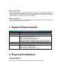
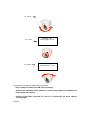
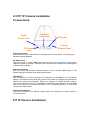
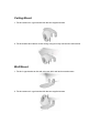
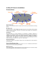
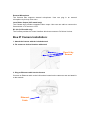
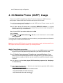
Multi-Profile
Network Cameras:
Pan/Tilt, Dome & Box Type
Quick Start Guide
2008 May
Table of Contents
1. System Requirements............................................................................................ 3
2. Physical Installation .............................................................................................. 3
2.1 Indoor IP Dome Camera Installation .......................................................... 5
2.2 Vandal IP Dome Camera Installation.......................................................... 7
2.3 P/T IP Camera Installation .......................................................................... 9
3. Camera administration ........................................................................................ 13
4. 3G Mobile Phone (3GPP) Usage ........................................................................ 15
About multi-profile
Multi-profile stands for simultaneously video streams. The Network Camera can
generate MPEG4 and MJPEG streaming simultaneously to different clients. Moreover,
the resolution can be different from one client to another. This state-of-art design is
considerable to fit in various network environments.
Before Installation
Before installation, please be sure to read this quick installation guide and user’s manual
carefully to complete machine installation.
1. System Requirements
Multi-Profile Network Camera
Network Environment
Network Interface
10/100MBase-TX Ethernet
Monitoring System Recommended for Internet Explorer 6.0 or later
System Hardware
· CPU: Pentium 4, 2GHz or above
· Memory Size : 512 MB or above
· VGA card resolution : 1024 x 768 or above
- Sound card: for 2-way audio funciton
· Network bandwidth: In VGA resolution mode, minimum upload
bandwidth is 1M bit. In QVGA or QQVGA mode, no limitation
System Requirement for Viewer & Recorder Application
Support OS
Win 2000 , Win XP, Win Vista
System Hardware
16 cameras surveillance application
· CPU: Pentium D, 2.8GHz or faster
· Memory Size : 512 MB or above
· VGA card resolution : 1024 x 768 or above
2. Physical Installation
Connections:
All dome type cameras have the same cables for connection as below:
RJ45 LAN
(Vandal dome is male type
IR IP Dome is female type).
Video out
RS485 & DI/DO
(Connect to a TEL box)
Line in
12V DC in
Line out
1. RJ45 LAN socket: Connect to PC or Hub/Switch.
For connections to 10Base-T Ethernet or 100Base-TX Fast Ethernet cabling. This
Ethernet port built N-Way protocol can detect or negotiate the transmission speed of the
network automatically. Please use Category 5 “straight through” cable to connect the
Network Camera to a 100Mbps Fast Ethernet network switch or hub.
Note that, in case you need to connect the device to PC or notebook directly, you should
use cross over cable instead.
2. RS-485: Connect to a local keyboard controller.
DI/ DO: Connect to sensor in and alarm out devices
Inside the TEL box:
Name
Function
12VDC DC 12V (50mA maximum)
GND
GND
D+
RS485 data +
DRS485 data DI
Digital signal input
DO
Digital signal output
3. Local Video output (BNC port)
The Network Camera also provides composite video output. User can use BNC video
cable to connect the Network Camera with a TV monitor or VCR.
4. DC-in Jack
The input power is 12VDC. Note that supply the power to the Network Camera with the
power adapter included in package.
5. Line in (audio in)
Connect an audio input source to the speed-dome network camera.
6. Line out (audio out)
Connect a loud speaker to the speed-dome network camera. This function is for voice
alerting and two-way audio.
2.1 Indoor IP Dome Camera Installation
1. Drill 20mm (3/4") holes in the ceiling or wall and then align the mounting plate to the
holes you have made as below.
Ceiling Top Plate
2. Directly install on any horizontal or vertical surface
3. Alternatively, fixed with wall mount bracket (option).
Option: Bracket
4. Camera Adjustment:
Tilting View
Angle range is 0o~90o
4.1. X-axis
4.2. Y-axis
Rotating View
Angle range is 0o~90o
4
4.3. Z-axis
Panning View
Angle range is 0o~180o
5. Connect the necessary cables and connectors:
- Plug-in Ethernet Cable into LAN port (necessary)
- Connect the attached power adapter to camera and plug-in this adapter into
power outlet (necessary)
- Connect Video BNC connector to a local TV if necessary (to check camera
viewing angle)
6. Done.
2.2 Vandal IP Dome Camera Installation
1. Use the provided L-wrench, loosen the vandal-resistant housing cover (with screws
still attached on the cover).
2. Set the mounting base onto the wall or ceiling and center it over the mounting hole, using the
supplied four retaining screws to secure the main body.
3. Set the proper image by moving the camera body (3-axis) and set the focus by turning
the lens to the left or right direction.
4. When the camera focus adjustment has been completed, use the provided L-wrench to
fasten the vandal-resistant housing to the main body.
5. When using the side conduit cabling, it is suggested to cover the cables using metal
covers (to prevent external damage and for waterproof prevention), and wined the
waterproof adhesive tape (P.T.F.E. THREAD SEAL TAPE) onto the metal cover before
installation.
6. Connect the LAN cable to Ethernet’s switch or hub, the video cable to video output to
the monitor or other video device through a 75 Ohms type coaxial cable and the
DC-Jack to the power source.
7. Vari-Focal Dome Operation Guide: Once the picture appears on the monitor, open
the cover and adjust the lens wrench to “NEAR←→FAR”, get the view zoom that you
desire, and then adjust the focus wrench of the lens to obtain the best picture. After
adjustment, tighten both wrenches.
Zoom Adjustment
NEAR
TELE
Focal Adjustment
FAR
WIDE
8. Connect the necessary cables and connectors:
- Plug-in Ethernet Cable into LAN port (necessary)
- Connect the attached 12V power adapter to camera and plug-in this adapter
into power outlet (necessary)
- Connect Video BNC connector to a local TV if necessary (to check camera
viewing angle)
9. Done
2.3 P/T IP Camera Installation
Connections:
Audio
Output Jack
Antenna
Connector
DC Power
Jack
LAN Socket
Factory
Default Reset
Audio Output Jack
It allows this device to output audio or alerting sound. Connect with a 3.5Ø phone jack
speaker (external adaptor)
DC Power Jack
The input power is 12VDC. Note that supply the power to the Camera with the power
adapter included in package. Otherwise, the improper power adapter may damage the
unit and result in danger.
Antenna Connector
User can attach the included wireless antenna to this connector (SMA type) or use
another high-gain antenna to get higher performance.
LAN Socket
The LAN socket is a RJ-45 connector for connections to 10/100Base-TX Fast Ethernet
cabling. This Ethernet port built N-Way protocol can detect or negotiate the transmission
speed of the network automatically. Please use Category 5 “straight through” cable to
connect the Network Camera to a 100Mbps Fast Ethernet network switch or hub. Note
that, in case you need to connect the device to PC or notebook directly, you should use
“cross-over” cable instead.
Factory Default Reset
This button is hidden in the pinhole. Please refer to the Appendix A in this manual for
more information.
P/T IP Camera Installation:
Ceiling Mount
1. Fix the camera to L-type bracket with the two supplied screws
2. Fix the bracket and camera to the ceiling using two holly wall anchors and screws
Wall Mount
1. Fix the L-type bracket to the wall using two holly wall anchors and screws
2. Fix the camera to L-type bracket with the two supplied screws
2.4 Box IP Camera Installation
Connections:
Video Out
Audio
Output Jack
DC Power
Jack
DC Iris
LAN Socket
External MIC
Jack
Power &
LAN LED
Factory
Default Reset
DI/DO
Connector
Audio Output Jack
Audio-out Jack allows this device to output audio for two-way communication or alerting
sound.
DC Power Jack
The input power is 12VDC. Note that supply the power to the Camera with the power
adapter included in package. Otherwise, the improper power adapter may damage the
unit and result in danger.
LAN Socket
The LAN socket is a RJ-45 connector for connections to 10Base-T Ethernet or
100Base-TX Fast Ethernet cabling. This Ethernet port built N-Way protocol can detect or
negotiate the transmission speed of the network automatically. Please use Category 5
“straight through” cable to connect the Network Camera to a 100Mbps Fast Ethernet
network switch or hub. Note that, in case you need to connect the device to PC or
notebook directly, you should use “cross-over” cable instead.
Factory Default Reset
This button is hidden in the pinhole. Please refer to the Appendix A in this manual for
more information.
Power & LAN LED (green color)
This LED is used to indicate whether DC power is on or not. In addition, this LED will be
flashing while network accessing via Ethernet.
DI/DO Connector
The Camera provides a terminal block with 4 pins of connectors for DI and DO. Please
refer to the Appendix B in this manual for more information.
External Microphone
The Camera also supports external microphone. User can plug in an external
microphone to pick up voice more.
Local Video Output (CCD model only)
The Camera also provides composite video output. User can use cable to connect the
Camera with a TV monitor or VCR.
DC Iris (CCD model only)
The Camera provides Iris control interface which can connect to DC-driver Iris lens.
Box IP Camera Installation:
1. Attach the Camera with the included stand
2. Fix camera to desired location with stand
Fixed it by
Screws
3. Plug an Ethernet cable into the Camera
Connect an Ethernet cable to the LAN socket located on the camera’s rear and attach it
to the network.
Ethernet
Cable
4. Connect the external power supply to Camera
Connect the attached power adapter to the DC power jack of the camera. Note: Use the
power adapter, 12VDC, included in the package and connect it to wall outlet for AC power.
Power
Cable
Once you have installed the camera well and powered it on, the power LED will turn on. It
means the system is booting up successfully. Furthermore, if you have a proper network
connection, and access to the camera, the LED will flash green under wired mode.
5. Done
3. Camera administration
When you installed your networked device over your network environment, to start Network
Camera web configuration, you must have the web browsers installed on computer for web
management.
- Microsoft internet Explorer 6.0 or higher
At first, user may use “IP Wizard” utility to search all networked devices in the LAN.
Use “IP Wizard” to locate IP address
Press “Search” button.
IP Wizard will list all networked devices in the LAN:
Wizard function:
The utility featured with “Wizard” function to help user to modify the IP parameters of the
installed network devices. User can step by step to setup IP address, username and
password.
Username and Password:
The networked devices will prompt for User Name and Password. Default username is:
admin, leave password blank.
Note 1: If no IP address is assigned within 30 seconds, the networked device will
automatically assign 192.168.0.100. User may now open your web browser, and key in
http://192.168.0.100 in the address bar of you web browser to logon Network Camera’s
web configuration page.
Note 2: If you have problem when connecting the network camera to a router, please read
user’s manual inside CD, the section “Installation to a router”.
After connected to networked device, the device will prompt for User name and Password.
For the first time, please enter: admin as username to continue machine Web
Management.
If difficulty is met, please refer to the following steps to establish the connection:
-
The networked device must be installed and powered ON.
-
If the networked device’s default IP Address (192.168.0.100) is already used by
another device, the other device must be turned OFF until the device is allocated a
14
new IP Address during configuration.
4. 3G Mobile Phone (3GPP) Usage
The device is 3GPP compatible by default. To view live video over 3GPP, here is a
briefly steps. Please check user's manual inside product CD for detail
Step 1: You must apply a 3G mobile phone with 3GPP service. Please contact your 3G
telecom service provider for detail.
Step 2: Check that the IP camera has a completely PUBLIC IP address, i.e. no ports
blocked by a firewall. It is highly recommended that you have a static and public IP
address without any firewall blocked
Step 3: check RTSP port and the default port is 554.
Step 4: Bitrate
Setting Î Video Î MPEG4/QQVGA Î Bit rate, set the maximum bit rate to lower
than 128 kbit/s.
To use the 3GPP function, in addition to previous section, you might need more information
or configuration to make this function work.
Note that to use the 3GPP function, it strongly recommends to install the Networked Device
with a public and fixed IP address without any firewall protection.
Mobile Phone Dialing procedure:
Step 1: Contact your cell phone provider and make sure that 3GPP service is available.
Support cell phone list please keep contact with your Network Camera sales.
Step 2: Enable “internet access” function on your mobile phone. Some
telecom will automatically download the setup profile to your mobile phone;
some telecom need you call the service center to enable the internet access
function
Step 3: Choose a verified video player, RTSP streaming supported (ex. Realplayer
or PacketVideo)
Step 4-1: Open the video player.
(for firmware version 2.x):
Base on your requirement, type either URL address
rtsp://host/avN for both audio and video tracks.
rtsp://host/videoN for video track only.
rtsp://host/audio for audio track only.
15
Where host is the host name or IP address of the camera, and N is the number of the profile
(between 2 and 3) for the video stream.
Step 4-2: For firmware version 3.x:
rtsp://host/mpeg4/media.3gp
Where host is the host name or IP address of the camera.
IP camera video or audio will show up on your player now!
Made in Taiwan
All Rights Reserved 2008
16