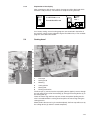
1
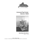
Liner Tape Sewing Machine
Series 1500/70
Operating Instructions
Version 1.0, 8-11-1999 – GB
© 1999 Beisler GmbH
Frohnradstr. 10 • D-63768 Hösbach • Phone-No. Service: +49-6021-501940 • Fax: +49-6021-540061
These operating instructions contain the following parts:
Part 1:
Operating instructions (pages 1-xx)
adresses to the operator of the machine, that means the person
who works at and with the machine.
Part 2:
Mechanics manual (pages 2-xx)
is used for the putting into operation, adjustment, troubleshooting
and maintenance of the machine and adresses to qualified staff
only.
Please obtain all safety, warning and other hints and regulations in this
manual.
The machine described in this manual is subject to further technical
development. Technical modifications are integrated without further notice.
Part 1
Operating instructions
Hint
These operating instructions contain all information required for the operation
of the machine. It adresses to the operator of the machine, that is the person
that works at and with the machine. Please obtain all rules and regulations.
Contents
Page
Part 1
Operating instructions ...................................................................................... 1-1
1
1.1
1.2
1.3
1.4
1.5
1.6
1.7
1.8
1.9
Security advice and warning hints ................................................................... 1-3
Classification ........................................................................................................ 1-3
General security advice and warning hints ........................................................... 1-3
Introduction .......................................................................................................... 1-4
Target groups of the manual ................................................................................ 1-4
Authorized person ................................................................................................ 1-4
Contents of this manual ....................................................................................... 1-5
Range of validity .................................................................................................. 1-5
Copyright ............................................................................................................. 1-5
Additional regulations ........................................................................................... 1-6
2
2.1
2.2
2.3
2.4
2.5
2.6
Preliminary remarks .......................................................................................... 1-7
Limitation of liability .............................................................................................. 1-7
Guarantee regulations ......................................................................................... 1-7
Use as agreed ..................................................................................................... 1-8
Description of the machine .................................................................................. 1-8
Main parts of the machine .................................................................................... 1-9
Technical data .................................................................................................... 1-10
3
3.1
3.2
3.3
3.4
3.5
Switch on/off, Emergency-Stop, Restart ........................................................ 1-11
Switch on ............................................................................................................ 1-11
Switch off ............................................................................................................ 1-11
Emergency-Stop using the main switch .............................................................. 1-11
Restart after Emergency-Stop ............................................................................ 1-12
Adjust compressed air pressure ........................................................................ 1-12
4
Operation of the sewing head ......................................................................... 1-12
5
5.1
5.2
5.3
5.3.1
5.3.2
5.4
5.5
5.6
5.7
Components of the machine ........................................................................... 1-13
Racks for liner tape and thread spools ............................................................... 1-13
Tape pulling device (option) ............................................................................... 1-13
Operation device ................................................................................................ 1-14
Components of the operation device .................................................................. 1-14
Explanation of the display .................................................................................. 1-15
Sewing head ...................................................................................................... 1-15
Main switch ........................................................................................................ 1-16
Collecting basket ............................................................................................... 1-16
Foot pedal .......................................................................................................... 1-16
1-1
1-2
6
6.1
6.2
6.3
6.3.1
6.3.2
6.4
6.4.1
6.4.2
Operation of the machine ................................................................................ 1-17
Controls ............................................................................................................. 1-17
Production sequence ......................................................................................... 1-17
Program control ................................................................................................. 1-18
Available sewing programs ................................................................................ 1-18
Select another sewing program ......................................................................... 1-18
Additional settings at the operation device ......................................................... 1-19
Select operation language ................................................................................. 1-19
Adjust display contrast ....................................................................................... 1-19
7
7.1
7.2
7.2.1
7.2.2
7.2.3
7.3
Cleaning and maintenance.............................................................................. 1-20
Cleaning of the machine .................................................................................... 1-20
Maintenance ...................................................................................................... 1-20
Check oil level in the sewing head ..................................................................... 1-20
Empty collecting basket ..................................................................................... 1-21
Empty warer separator ....................................................................................... 1-21
Troubleshooting hints ......................................................................................... 1-21
1
Security advice and warning hints
1.1
Classification
Three different types of hints are used in this manual, which are indicated
with different symbols and signalling words:
DANGER
This indicates a possibly dangerous situation or action, which may cause
injuries to persons or severe damage to the machine.
ATTENTION
This indicates a situation or action, which may cause damage to the machine.
Hint
This indicates hints for a better use and other helpful information or hints.
Please obey all rules and regulations.
1.2
General security advice and warning hints
Danger
Danger might arise for persons, things and environment by inappropriate
operation of this machine. Installation and maintenance duties may only be
carried out by authorized staff.
Danger
Danger of injuries in the range of the sewing head! Don’t grasp into the
affected area of the needle during the sewing process!
Danger
Before any operations at or with the machine (putting into operation, operation, maintenance, repair, etc.) the person carrying out has to read and understand this manual with each appendix completely.
Danger
Before carrying out maintenance or repair duties, the mains supply must be
cut off. Additionally pressure must be released from the pneumatical system.
Attention
The machine will be destroyed by a connection to a wrong mains voltage!
See the section ‘Technical data’ before connecting the power supply.
1-3
1.3
Introduction
The manual on hand is divided into two main sections:
• the Operating Instructions with all information required for the operation
and daily cleaning and maintenance routines of the machine;
• the Mechanics and Programming Instructions with all further maintenance
and repair duties and a instruction for the programming of sewing programs.
1.4
Target groups of the manual
The two sections of the manual are adressed to:
Operating Instructions to the operator of the machine which is the person
that works at and with the machine;
Mechanics Manual
to qualified staff which is trained to estimate the
working duties and recognize possible danger at an
early time.
ATTENTION
All actions at and/or with the machine may only be executed by authorized
persons, who have read and understood the corresponding parts of this
manual.
Especially the following actions are subject to this regulation:
• operation including preparation, troubleshooting during production, cleaning, care
• Servicing (maintenance, inspection, repair)
• Transportation
ATTENTION
A specialist in accordance to IEC 364 and DIN EN 60204-1 is regarded as
qualified staff.
1.5
Authorized person
DANGER
There is danger to human beings, things and environment through inandequate operation of this machine. Installation and maintenance duties may
only be carried out by authorized staff.
Persons are regarded as authorized, who are able to recognize possible
danger and judge the assigned duties from their technical education and
experience.
Operator of the machine
Persons are regarded as authorized, who were trained in the operation of this
machine and have read and understood the first part of this manual completely.
Staff for installation, preparation, programming and maintenance
Persons are regarded as authorized, who were trained in all aspects of the
machine and have read and understood the complete manual on hand.
1-4
1.6
Contents of this manual
The Operating Manual for the Liner Tape Sewing Machine, series 1500/70
contains the following parts:
1. Operating Instructions
2. Mechanics Manual
3. Electrical wiring plans
4. Parts list
5. Operating Manual of the sewing head
Please check the documents delivered with the machine for completeness.
1.7
Range of validity
This operating manual is valid for Liner Tape Sewing Machines manufactured
by Beisler named ‘Liner Tape Sewing Machine, series 1500/70’.
This operating manual is not valid for the sewing head applied in the machine. Please refer to the operating manual of the sewing head delivered with
the machine, for which we don’t take any liability.
Further security advice (verbal and written) for this machine or the components will not be repealed by this manual.
1.8
Copyright
© 1999 Beisler GmbH, Hösbach
Liner Tape Sewing Machine
The ‘Liner Tape Sewing Machine, series 1500/70’ and this operating manual
with all parts are protected on copyright. Manufacture without license will be
prosecuted by law. All rights reserved on this operating manual, including
reproduction in any thinkable way, either by copying, printing, on any data
recording media or in translated form. Reproduction of this operating manual
- even in extracts - only with written approval by Beisler GmbH.
This operating manual contains a description of the product, but no promise
of certain qualities or results of use. The operating manual has been proved
before delivery. The Beisler GmbH takes the liability, that this operating
manual if free of errors reducing its value for the estimated use. The editors
don’t take liability for consecuting damage arising through application of the
operating manual. We are always thankful for hints and ideas.
The technical standard of the common delivery of product and operating
manual by the Beisler GmbH is decisive, if not other information is given.
Technical changes without prior notice are reserved, previous operating
manuals loose validity.
The general conditions of sales and delivery of the Beisler GmbH are valid.
Do you have questions or problems with installation or putting into operation?
Don’t hesitate to call us.
Beisler GmbH
Frohnradstr. 10 - D-63768 Hösbach
Tel: (+49) 6021 / 50 19 0
Fax: (+49) 6021 / 50 19 10
1-5
1.9
Additional regulations
This manual must be available at the machines location at any time.
The operator has to assure that only authorized persons work at and with the
machine.
The operator is obliged to check the machine for visible damage and faults at
least once per shift. Visible changes must be reported to the corresponding
official immediately after discovery.
The company using this machine has to assure that the machine is always
operated in faultless condition. Security installation may not be dismounted or
put out of function.
If security installation must be dismounted for preparation, repair or maintenance of the machine, they must be mounted immediately after the duties
have been terminated.
Unauthorized changes to the machine exclude liability of the manufacturer for
damages.
1-6
2
Preliminary remarks
2.1
Limitation of liability
We guarantee the faultless functioning of our product in accordance with our
advertising, the product information edited by the Beisler GmbH and this
manual. Further product-features are not guaranteed. We take no liability for
the economy and faultless function if the product is used for a different
purpose then that described in the chapter „Use as agreed“.
Compensation claims are generally impossible, except if intention or culpable
negligence by the Beisler GmbH is proved, or if assured product-features are
not provided. If this machine is used in environments, for which it is not suited
or which do not represent the technical standard, we are not responsible for
the consequences.
We don’t accept responsibility for damages at installations and systems in
the surroundings of this machine, which are caused by a fault of the product
or an error in this manual.
We are not responsible for the violation of patents and/or other rights of third
persons outside the Federal Republic of Germany.
We are not liable for damages, which result from improper operations according to this manual. We are not liable for missed profit and for consecuting
damages due to non-regardance of security advices and warning hints. We
don’t accept liability for damages which resulted from the use of tools and
accessoires which are not delivered and/or approved by the Beisler GmbH.
The prdocuts of the Beisler GmbH are designed for a long life. They represent the standard of technique and science and were checked on all
functions individually before delivery. The electrical construction corresponds
to the current norms and regulations, particularly DIN 5713 / VDE 0113.
Beisler GmbH is doing product and market research for the further development and permanent improvement of their products. In the case of faults
and/or technical trouble please contact the Beisler GmbH service staff. We
assure that suitable measures will be done immediately.
The Beisler GmbH guarantee regualtions are valid, which we will send to you
on demand.
2.2
Guarantee regulations
We guarantee the fault-free functioning of the ‘Liner Tape Sewing Machine,
series 1500/70’ according to this operating manual except the tools for a time
range of six months after delivery. If the machine is used in double- or tripleshift operation, the term of guarantee is reduced to three or two months.
The term of guarantee starts with the date of delivery to the customer, independant from the time of putting into operation. Guarantee will be spoiled, if
the machine isn’t installed and operated according to this operating manual
and the regulations given by the Beisler GmbH staff. A cost-free repair is only
possible, if all regulations considering storage, transportation and putting into
operations have been obeyed.
Customers and third persons may only mesh with the machine after getting a
written approval by the Beisler GmbH. The Beisler GmbH takes no responsibility for injuries and damages arising from non-obeyance of this stipulation.
All warranty will be spoiled in this case.
The Beisler GmbH takes no responsibility for faults of the machine as consequence of defective or functional faulty equipment in the surrounding of the
machine or by the use of accessoires, which were not delivered by the
Beisler GmbH.
The general conditions of sale and delivery of the Beisler GmbH are valid.
1-7
2.3
Use as agreed
The ‘Liner Tape Sewing Machine, series 1500/70’ has been developed for the
sewing of the trouser liner tape from the roll at closed trouser legs. As an
option, the machine may be equipped with a pinking mechanism.
DANGER
This machine has been developed and build for a certain purpose. Adaptions
may influence security equipments negatively. We recommend to contact our
service staff in such a case.
2.4
Description of the machine
The ‘Liner Tape Sewing Machine, series 1500/70’ allows the rational sewing
of the trouser liner tape to closed trouser legs. The machine is equipped with
several supply devices and a sewing head.
As an option, the machine can be equipped with a pinking mechanism, with
which the trouser legs can be pinked below the liner tape automatically
during the sewing process.
All components of the machine are mounted on a base frame made of
square steel pipes and controlled by an innovative micro-processor system.
Machine operation is achieved with an operation device. Here you can open
several control programs, define new programs and check all machine
components individually for maintenance and repair duties.
1-8
2.5
Main parts of the machine
1
2
9
3
10
4
5
11
6
7
12
8
13
14
15
1
2
3
4
5
6
7
8
9
10
11
12
13
14
15
Rack for liner tape rolls
Tape pulling device (option)
Liner tape
Sewing head
Metering
Cutting device
Sewing foot
Collecting basket
Spool rack
Lamp (option)
Operation device
Working table
Main switch
Foot pedal
Adjustment of working table height
Further information on the components of the machine are contained in the
coming chapters.
1-9
2.6
Technical data
Dimensions (LxWxH)
Table height
Weight
El. connection
Air connection
Power consumption
Air consumption
1-10
2.000 x 700 x 1.700 mm
690 ... 950 mm (adjustable)
120 kg
220 V AC
min. 5 bar
0,7 kW
est. 3 l/part
3
Switch on/off, Emergency-Stop, Restart
1
2
3.1
Switch on
Hint
The machine must be connected to the power and compressed air supply
before it can be switched on.
The main switch (2) is located at the machine front, on the right handed side
beneath the working table.
Turn the main switch (2) clockwise until it engages. The grip of the switch
points on the marking „1 – ON“. The display of the operation device (1)
shows the main screen.
3.2
Switch off
Turn the main switch (2) counter clockwise until it is released. The grip of the
switch points on the marking „0 – OFF“.
3.3
Emergency-Stop using the main switch
The main switch (2) is located at the machine front, on the right handed side
beneath the working table.
Turn the main switch counter clockwise, until it is released. All movements of
the machine will be stopped immediately, the machine will be free of electrical
power instantly.
1-11
3.4
Restart after Emergency-Stop
ATTENTION
Before you restart the machine you should remove the reason for the
Emergency-Stop. Contact the responsible technician in any doubtful case.
The machine may only be restarted after the reason for the Emergency-Stop
has been removed.
Switch on the machine using the main switch. The current program number
will be imaged in the display of the operation device. The machine is ready to
use.
3.5
Adjust compressed air pressure
The machine needs an air pressure between 5 and 6 bar. This is adjusted at
the air supply unit:
1
2
3
4
5
1 Air connecting hose
2 Control to adjust the air pressure
3 Pressure gauge
4 Collector for condensing water
5 Release valve for condensed water
Check the air pressure at the pressure gauge (3). If the indicated value
differs from 6 bar, adjust the pressure by turning the black control (2).
4
Operation of the sewing head
The operation of the sewing head is explained in the separate manual of the
sewing head, which is part of the machine’s documentation.
Please obtain all rules and regulations.
1-12
5
Components of the machine
The machine contains several components, which are arranged according to
their function:
1. Racks for liner tape and thread spools.
2. Tape pulling device (option) beneath the liner tape rack.
3. Operation device above the working table.
4. Sewing head with metering, cutting device and pinking mechanism
(option).
5. Main switch to switch the machine on and off.
6. Collecting basket for threads and cutted cloth.
7. Foot pedal to start the program sequence.
5.1
Racks for liner tape and thread spools
The machine is equipped with several racks for liner tape rolls and thread
spools. A fast change between different colours and qualities is achieved by
that.
Thread spools are plugged on the holding devices, the liner tape racks are
equipped with additional roll holding devices, which can be pushed on and
pulled off.
5.2
Tape pulling device (option)
1
5
2
6
3
7
4
8
With the tape pulling device (option), an absolutely tension-free insertion of
the liner tape into the machine is achieved.
The liner tape (1) comes around the roll (2) and is driven between pressure
roll (3) and pull roll (4). Then it comes around another roll (5), passes the
frame (7) of the pull switch and around a last roll (6) out of the metering.
If liner tape is inserted into the sewing head by the metering, the frame (7) of
the pull switch is pressed upwards and switches a contact. The pull roll (4)
starts turning and transports liner tape, until the pull switch is switched off
again.
You can set the duration at the control (8), how long the pull roll (4) shall
continue turning after the pull switch had been switched off.
1-13
5.3
Operation device
1
2
3
4
5
6
You can operate the machine during production using the operation device.
You can open existing programs and program new ones.
1 Display
2 Cursor keys
3 Special key
4 Minus/Plus keys
5 Key tape transport (threading up)
6 Key tape cutting
5.3.1
Components of the operation device
The components of the operation device provide the following functions:
Display (1):
all information required for the operation of
the machine are imaged here.
Cursor keys (2):
use them to move the cursor and mark all
required commands and options.
Special key (3):
press this key if several information is
required for an adjustment.
Minus/Plus keys (4):
use them to enable/disable functions, reduce/increase numeric values and select
programs.
Key tape transport (5):
use it to transport the liner tape manually
with the metering at the sewing head; allows
an easy threading-up.
Key tape cutting (6):
triggers a tape cutting; after cutting, you can
pull out the liner tape from the machine.
1-14
5.3.2
Explanation of the display
After switching on with the main switch, the program will be displayed which
had been used previously. The machine is ready for sewing instantly:
COVER
001
POS
[ 0]
P1 METERING: 115
P2 AUSZACKER: 220
: 3400
STEP: 1
PRG: 1
As a factory setting, several sewing programs are contained in the buffer of
the machine, which can be selected using the Plus/Minus keys. The available
programs are listed further below.
5.4
Sewing head
1
2
3
4
5
6
1
Liner tape
2
Sewing head
3
Metering
4
Cutting device
5
Sewing foot
6
Pinking mechanism
The liner tape (1) comes from the tape pulling device (option), comes through
the pull and pressure roll of the metering (3), through the cutting device (4) to
the sewing foot (5).
There the trouser leg and liner tape are sewed, the optional pinking mechanism is located behind the sewing head and pinks the trouser leg during the
sewing process.
Shortly before the trouser leg is sewed completely, the liner tape will be cut by
the cutting device (4) and then sewed completely.
1-15
5.5
Main switch
The main switch is located at the front side of the machine, right-handed
beneath the working table. Use it to switch the machine on and off.
5.6
Collecting basket
1
The cloth cut by the pinking mechanism and cut threads are collected in this
basket.
5.7
Foot pedal
1
Use the foot pedal to start the program sequence. Two ways of switching
have to be distinguished:
Press forward
weight on the foot tip and tilting the foot pedal
forward;
Press backward
weight on the heel and tilting the foot pedal backward.
1-16
6
Operation of the machine
6.1
Controls
1
2
1 Operation device
2 Foot pedal
Please see chapter 5 for explanations on the controls.
6.2
Production sequence
The Liner Tape Sewing Machine, series 1500/70 works semi-automatic with
high production speed. The operator of the machine has to:
• select the desired sewing program;
• align the fabrics correctly;
• start the sewing process using the foot pedal;
• supervise the fault-free functioning of the machine.
The production sequence contains the following steps:
1.
Align the trouser part with the inside seam under the sewing foot.
2.
Press the foot pedal forward, the sewing foot is lowered, the sewing
and the optional pinking start.
3.
Shortly before seam end, press the foot pedal backward, the liner tape
will be cut and the sewing of the rest of the liner tape starts.
4.
At seam end, the threads will be cut, the sewing foot lifted and the
trouser part blown out.
1-17
6.3
Program control
Hint
This machine is controlled with programs, which are contained in the memory
of the machine and can be opened by the operator. The modification of
existing and the programming of new sewing programs should be reserved to
experienced and qualified personell. The possibilities are explained in the
second part of this manual.
6.3.1
Available sewing programs
In the daily production, the operator will only have to open one of the existing
sewing programs. The following programs are available as a factory setting:
6.3.1.1
Machines without pinking mechanism
Prog.
Description
001
Program for the sewing of the liner tape without pinking the hem
edge
parts and threads are blown out after seam end.
Program for threading up the liner tape
press forward the foot pedal after inserting the liner tape into the
metering; the tape will be threaded up and cut; then the metering
will be swung in; press the foot pedal forward shortly, the liner tape
will be pushed forward to the needles.
002
6.3.1.2
Machines with pinking mechanism
Prog.
Description
001
Program for sewing the liner tape with pinking the hem edge
the pinking is done with low pinking pressure; parts and threads will
be blown out after seam end.
002
Program for threading up the liner tape
press forward the foot pedal after inserting the liner tape into the
metering; the tape will be threaded up and cut; then the metering
will be swung in; press the foot pedal forward shortly, the liner tape
will be pushed forward to the needles.
003
Program for sewing the liner tape with pinking the hem edge for
difficult cloths
the pinking is done with high pinking pressure; parts and threads
will be blown out after seam end.
004
Program for sewing the liner tape without pinking the hem edge
parts and threads will be blown out after seam end.
The currently selected program is imaged in the upper left corner of the
display.
6.3.2
Select another sewing program
1. Move the cursor to the program number.
2. Press the Plus/Minus key repeatedly, until the desired program number is
displayed.
1-18
6.4
Additional settings at the operation device
The operator may not open the Setup pages of the machine control. This
should be preserved to especially educated and experienced technicians.
You have to enter the machine code to open the Setup pages.
Attention
Damage to the machine due to inadequate programming possible! The
machine code should be kept secret and accessible to persons only, who are
allowed to program and setup the machine.
Only two settings may be executed by the operator:
• select the operation language;
• adjust display contrast.
6.4.1
Select operation language
Position the cursor on the program number and press the Minus key once.
This will be displayed:
PROG.
000
: 3400
[
]
DEUTSCH
XXX
Use the arrow keys to move the cursor on the displayed operation language
(here: deutsch = german) and press the Plus key, until the desired operation
language is displayed.
Move the cursor back on „000“.
Hint
The descriptions in the sewing programs will always be displayed in the
language that had been used to enter them.
6.4.2
Adjust display contrast
Open page „Program 000“ (see 6.4.1) and position the cursor on the halffilled circle symbol. Press the Plus or Minus key to adjust the contrast of the
display.
Position the cursor on „000“ and press the Plus key to select a sewing
program.
1-19
7
Cleaning and maintenance
DANGER
Possible injuries due to improper execution of cleaning and maintenance
duties! The operator of the machine may only carry out the cleaning and
maintenance duties described in this section. Further measures are reserved
to the responsible service technician.
7.1
Cleaning of the machine
Hint
To achieve the value and daily functionality of this machine, it should always
kept clean and free of production waste.
Clean the machine components as described:
Operation device
clean it using a dry, clean and lint-free cloth; heavy
dirt can be removed using a slightly saturated
cloth.
Complete machine
use a vacuum cleaner daily and if required to clean
the machine.
7.2
Maintenance
ATTENTION
Damage to the machine due to inadequate maintenance possible! The
execution of the maintenance duties should be reserved to experienced and
especially qualified staff. The required measures are described in the
mechanics manual in the second part of this documentation.
7.2.1
Check oil level in the sewing head
There is a window in the sewing head, where you can check the level of the
oil contained in the sewing head. Check the oil level daily and fill in required
oil immediately.
ATTENTION
Damage to the sewing head due to low oil! Check the oil level in the sewing
head daily and fill in missing oil immediately. Otherwise, the sewing head can
be damaged.
Information on the oil level check and filling in of missing oil is contained in
the operating instructions of the sewing head which is part of the machine
documentation.
1-20
7.2.2
Empty collecting basket
As an option the machine is equipped with a collection installation, which
collects the pinked hem edge and the cut threads from the range of the
sewing head.
The cloth and threads are collected in a basket, located beneath the working
table.
Turn the lower part of the basket to the left to screw it off. Empty the basket.
Mount the basket with a rotating movement to the right.
Hint
Please assure that the collected waste materials are treated in accordance to
the local waste regulations. Help to keep nature clean and preserve the
natural ressources.
7.2.3
Empty warer separator
The machine is equipped with a pressured air supply unit, where an automatic water separator is mounted.
If there is water in the cup, it will be released automatically if the pressured
air supply is closed.
7.3
Troubleshooting hints
Whenever an error or fault appears or an error message is imaged in the
display, the responsible technician have to be contacted.
1-21
1-22
Part 2
Mechanics manual
Hint
This part of the operating instructions contains all information required to put
the machine into operation and to do programming, troubleshooting and
maintenance. It adresses to trained technical personnel, which is able to
overview their tasks and recognize possible danger at an early moment. The
operating instructions given in part 1 of this manual are to be considered as
part of this mechanics manual.
Contents
Page
Part 2
Mechanics manual ............................................................................................. 2-1
1
1.1
1.2
1.3
Delivery, transportation, storage ...................................................................... 2-2
Delivery ................................................................................................................ 2-2
Transportation ...................................................................................................... 2-2
Storage ................................................................................................................ 2-2
2
2.1
2.2
2.2.1
2.2.2
2.3
2.4
Installation .......................................................................................................... 2-3
Technical data ...................................................................................................... 2-3
Mechanical installation ......................................................................................... 2-3
Unpack and put up ............................................................................................... 2-3
Connection of air supply....................................................................................... 2-4
Elektrical installation ............................................................................................ 2-4
First putting into operation .................................................................................... 2-5
3
3.1
3.2
3.3
3.4
3.4.1
3.4.2
3.4.3
3.4.4
3.4.5
3.4.6
3.5
3.5.1
3.5.2
3.5.3
3.5.4
3.5.5
3.5.6
3.6
3.7
3.7.1
3.7.2
3.8
Programming instructions and machine setup ............................................... 2-6
General hints ....................................................................................................... 2-6
Selection of the setup pages ................................................................................ 2-6
Setup page -01 .................................................................................................... 2-7
Setup page -02 .................................................................................................... 2-7
Position actor, turn direction, needle position ....................................................... 2-7
Revs (min. and max.) ........................................................................................... 2-8
Foot pedal ............................................................................................................ 2-9
Cover Page .......................................................................................................... 2-9
Store error messages .......................................................................................... 2-9
Enable access code ........................................................................................... 2-10
Setup page -03 .................................................................................................. 2-10
Thread cutter ..................................................................................................... 2-10
After thread cutting, time until sewing foot up ...................................................... 2-11
Presser foot ........................................................................................................ 2-11
Needle cooling ................................................................................................... 2-12
Step motors: pinking mechanism and metering ................................................. 2-12
Tape transportation ............................................................................................ 2-13
Setup page -10 .................................................................................................. 2-13
Program inputs and outputs ............................................................................... 2-14
Setup page of inputs and outputs ....................................................................... 2-14
Settings for this machine .................................................................................... 2-15
Meanings of the used symbols ........................................................................... 2-16
4
4.1
4.2
4.3
4.4
Use of the storage module ..............................................................................
Load data from the storage module ...................................................................
Write data on the storage module ......................................................................
Write single programs on the storage module ....................................................
Read a single sewing program into the machine control ....................................
2-18
2-18
2-19
2-19
2-20
5
5.1
5.2
5.3
Troubleshooting hints .....................................................................................
Error – possible solution .....................................................................................
Error messages in the display – possible solution ..............................................
Hints for several repair duties ............................................................................
2-21
2-21
2-21
2-22
2-1
1
Delivery, transportation, storage
1.1
Delivery
Hint
Check right after receiving the machine, whether all parts according to the
parts list are complete and without damage. Later compensation claims can’t
be accepted.
If you see damage to the transportation packing of the machine, which
indicates a possible damage to the delivered parts, don’t hesitate to claim this
to the transportation company.
1.2
Transportation
Generally it is possible to move the machine. Obey the following hints:
1. Cut off the power supply, release the pneumatical pressure.
2. Fix movable and loose parts.
3. Lift the base with a hoisting device and be sure to lift possible additional
devices (e.g. stacker). If the machine is equipped with transportation
casters (option), you will have to release the brakes at every caster.
4. Move the machine carefully to the new location.
Attention
Attention when moving the machine on sloping areas! Enormous pull power
arises from the machine weight.
1.3
Storage
If no other agreement is fixed, the following limitations have to be kept:
1. In closed rooms only.
2. Temperature range -10 ... +45 °C.
3. Humidity max. 80% non-condensing.
Attention
If stored or transported in improper environments, the machine can be
damaged severely. Damages may not be visible from the outside.
2-2
2
Installation
Attention
Installation and putting into operation may only be carried out by mechanically
and electrically qualified staff. These people must read and understand the
complete operating manual before starting.
2.1
Technical data
Dimensions
Table height
Weight
Power connection
Power consumption
Fuse
Pressure air
Req. air quality
Air consumption
2.2
1.000 x 700 x 1.700 mm (LxWxH)
690 ... 950 mm (adjustable)
120 kg
220 V AC
0,7 kW
15 A
min. 6 bar
free of oil
est. 3 NL/part
Mechanical installation
Attention
Check before starting the installation, whether the desired location meets the
requirements (see chapter 2.1, technical data). This is very important
regarding the stability of the ground.
2.2.1
Unpack and put up
1. Remove the packing material and possible transportation protections.
2. Position the machine on a solid and horizontal ground.
3. Level the machine to a horizontal stand using the adjustable frame feet.
2-3
2.2.2
Connection of air supply
1
2
3
4
5
1. Connect the air pipe (2) to your air system.
2. Open the air supply of your air system.
3. Level the air pressure to 6 bar using the control (1); the air pressure can
be read at the scale (3).
4. Water collected in the water separator (4) can be released by pressing on
the valve (5).
Attention
We recommend to switch off the air supply when the machine is not in duty.
Use the control (1).
2.3
Elektrical installation
Hint
All work at the electrical components of the machine may only be carried by
qualified staff (qualified electrical employee or instructed person according to
IEC 364 and DIN EN 60204-1).
Danger
Parts under electrical current! Without cutting off the power supply, you might
be injured severely. Please obey the security advice given in chapter 1.
Attention
The machine will be destroyed by connecting to a wrong mains voltage!
Check, whether the requirements from chapter ‘Technical data’ meet the
local conditions.
2-4
1. Use the power cord located at the backside of the machine.
2. Plug it into a socket.
3. Lay the cord in a way, that the danger of stumbling is avoided.
Danger
Danger to life from unsufficient grounding! Do a grounding according to DIN
EN 60204-1.
2.4
First putting into operation
This machine has been configured to the individual requirements of the
customer. The first putting into operation can be done easily:
1. Adjust the machine to a horizontal stand.
2. Connect power and air supply.
3. Switch on the machine using the main switch at the front side of the
machine.
4. Check all security systems for function and efficiency.
Danger
The machine may only be used for production purposes, after the safety
installations have been checked. If a safety installation doesn’t work
adequately, it must be repaired first.
As a factory setting, several production programs are contained in the buffer
of the machine. You may use one of them or create your own programs.
2-5
3
Programming instructions and machine setup
As a factory setting, 2 sewing programs (4 if the machine is equipped with a
pinking mechanism) are contained in the memory of the machine, which can
be selected and used by the operator. These programs had been programmed based on long experience and should be sufficient for the use of the
machine. The available programs are described in the first part of this manual.
Existing programs can be modified and adjusted to your personal requirements. You can also program completely new sewing programs. All modified
or new programs can be copied on a storage module for data recovery
purposes.
3.1
General hints
If you want to set or modify certain functions, you have to place the cursor
using the arrow keys on the icon of the function and change the setting using
the Plus/Minus keys.
At several functions you can press the Special key to open a setup page for
the specific function.
The machine setup can be modified on the following pages:
Setup -01 Machine type
Setup -02 Position actor, turn direction, needle position, revs, storing of
error messages, activate access code
Setup -03 Presser foot, photo cell
Setup -10 Inputs and outputs
3.2
Selection of the setup pages
1. Position the cursor on the program number and press the Minus key. This
will be displayed:
PROG.
000
: 3400
[
]
DEUTSCH
XXX
2.
3.
4.
5.
6.
2-6
Position the cursor on the left-handed „x“ below the key symbol.
Press the Minus key to change the „x“ to a zero.
Position the cursor on the middle „x“ and press the Minus key.
Position the cursor on the right-handed „x“ and press the Minus key.
Position the cursor on the program number 000 and press the Minus key.
Setup page -01 will be displayed.
3.3
Setup page -01
SETUP
-01
TYPE
MARKE
KETTENSTICH
Here you can set the machine type. The type „Kettenstich = chain stitch“
must be selected.
3.4
Setup page -02
SETUP
-02
P1
P2
Here you can see six icons which represent the machine functions. To select
a function, position the cursor on the respective icon and press the Special
key to open the setup page or press the Plus/Minus key to switch the function
on or off.
3.4.1
Position actor, turn direction, needle position
SETUP-02
---
III POS.
294
II POS.
0
170
0
I POS.
Turn direction
2-7
After opening the setup page, the cursor is positioned on the icon of the turn
direction. Press the Plus key to change the turn direction (viewed on the belt
disc).
Define needle zero-position
1. Position the cursor on the icon of the needle zero position.
2. Turn the hand wheel with impetus in the set turn direction until the angle
value below the turn direction icon changes.
3. Turn the hand wheel, until the needle stands at the top edge of the stitch
plate.
4. Press the Plus key to accept the value as zero position.
5. Press the Special key to leave the page or continue with the setting of the
needle top and bottom position.
Define needle top and bottom position
These positions are defined as a factory setting but can be modified:
1. Position the cursor on the stroke „II. Pos.“.
2. Turn the hand wheel into the set turn direction, until the needle stands in
the desired top position.
3. Read the angle value below the turn direction icon (est. 294).
4. Press the Plus or Minus key to enter the displayed value into the entry box
beside the stroke „II Pos.“.
5. Position the cursor on the stroke „I Pos.“.
6. Press the Plus or Minus key to enter the value „170“ into the entry box
beside the stroke „I Pos.“.
7. Press the Special key to leave the setup page.
3.4.2
Revs (min. and max.)
SETUP-02
MIN.:
MAX.:
400
[3600]
RESET
ON
Pull:
5400
75
100%
ACC.
80%
DEC.
Position the cursor on all sections listed below and set the recommended
values using the Plus or Minus key:
MAX.:
3600
MIN.:
400
ACC.
100 %
2-8
DEC.
80 %
Pull:
75
Press the Special key to leave the setup page.
3.4.3
Foot pedal
Hint
The settings contained here are set perfectly as a factory setting and may not
be modified.
3.4.4
Cover Page
P1
P2
SETUP-02
P1
P2
P
TXT
P
TXT
1:P1 METERING
5:P5 ...................
2:P2 AUSZACKER
6:P6 ...................
3:P3 ...................
7:P7 ...................
4:P4 ...................
VORRICHTUNG
8:P8 ...................
COVER N:1
Here you can enable parameters. Enabled parameters will be listed on the
cover page 001 and can be modified there, without accessing the machine
setup.
Move the cursor to the parameter to be enabled or disabled. Press the Plus
key. An enabled parameter is indicated by a triangle displayed to the left of it.
The cover page icon on setup page -02 must be enabled to allow the use of
the cover page. If it is enabled, the cover page will be displayed before
program page PROG 001. Open the page COVER 001, position the cursor
on the desired parameter and modify the setting by pressing the Plus or
Minus key.
3.4.5
Store error messages
2-9
S E T U P
-0 2
E R R O R
P A R T IA L
T O T A L
--:---:---:--
1 2 :1 5
0 4 :3 5
3 0 :0 0 %
3 8 :2 0
2 7 :1 5
4 0 :0 0 %
The last 16 error messages are documented on this page. They are listed
with the time of their appearance and the time period until the next error
message.
Press the Special key to leave this page.
3.4.6
Enable access code
Use the Plus key to enable (left) or disable (right) the icon of the access
code. If the access code is enabled, the code must be entered before a setup
page can be opened.
3.5
Setup page -03
SETUP
-03
S
Eleven icons are displayed here, but only five of them are enabled.
To enable/disable a function, position the cursor on the respective icon and
press the Plus/Minus key. A disabled icon is crossed out.
To select the setup page of a function, this function must be enabled. Then
position the cursor on the respective icon and press the Special key.
Hint
If the presser foot cannot be enabled, you will first have to switch off output
F1 on setup page -10. More explanations are given further below.
3.5.1
2-10
Thread cutter
SETUP-03
SOFT
START
(>>>) : 3
a: 900
[ms]: 70
: 400
The switch on delay and duration of the thread cutter are programmed here.
You should enter 70 ms as switch on delay and 400 ms as active duration.
Program three stitches with 900 revs in the page section „Soft Start“.
Press the Special key to close the page.
3.5.2
After thread cutting, time until sewing foot up
SETUP-03
0
400
600
There is no possibility in the thread cutting mode of programming the time
until the sewing foot is lifted after cutting the thread. As an alternative, the
function „Thread wiper“ is used.
On setup page -10, output F4 must be disabled. The thread wiper must be
enabled on setup page -03. Then you can program the times like shown in
the drawing.
3.5.3
Presser foot
SETUP-02
30V
(max)
[ms]
15 V
150
00
120
1. Position the cursor on the time of maximum power (left value in lower row)
2-11
2.
3.
4.
5.
6.
3.5.4
and press the Plus/Minus key until 150 ms is set. This assures that the
presser foot is lifted safely after seam end.
Position the cursor on the value of the holding voltage (upper row, value in
the middle of the display) and press the Plus/Minus key until 15 V is set.
This assures that the magnetic valve for the foot release will not be
overloaded.
Position the cursor on the value of the start delay (right edge) and enter
120 ms here. This time is required to assure that the sewing foot rests
safely on the cloth before sewing starts.
Position the cursor on both presser foot icons and set them to „Presser
foot up“ like shown in the picture.
Press the Special key to leave this page.
Check, whether the presser foot is programmed on „up“ on page „PROG
000“, too.
Needle cooling
SETUP-03
[ms] 100
The needle cooling must be enabled during the sewing and will be disabled
100 ms after seam end.
Press the Special key to leave this page.
3.5.5
Step motors: pinking mechanism and metering
The motor of pinking mechanism and metering are optimized as a factory
setting and should not be modified. Open the corresponding setup page to
check the settings:
1
SETUP-03
JS
KJ
KP
KA
IL
IH
2
80
2
1
10
1
6
3
80
2
1
7
1
11
4
80
8
8
8
1
10
80
8
8
8
1
10
All values must be set like shown in the drawing.
JS
jog speed: tape transportation speed for manual tape threading up;
KJ
speed factor in POS mode: tape transportation speed during program
sequence;
2-12
KP
speed factor in puller mode (1 ... 15): speed factor for the synchronous
operation (1 ... 7 = half step; 8 ... 15 = full step);
acceleration curve;
holding voltage in home position (1 ... 15): this should reduced to a
minimum for both motors to avoid over heating;
working voltage (1 ... 15): here you have to consider the
manufacturer’s information; if the working voltage is set too high, the
motors will be destroyed.
KA
IL
IH
ATTENTION
Damage to the motors due to inadequate settings! Before you modify one of
the values shown here (especially value IH), you should contact the Beisler
service staff.
3.5.6
Tape transportation
At the end of the sewing program, the liner tape will be inserted under the
sewing foot automatically that the next sewing process can start immediately.
The tape transportation distance is programmed in a way that the liner tape is
grasped by the needles at seam start.
To modify the transportation distance, you will first have to select the sewing
program, where you want to modify this distance. Move the cursor on „STEP
01“ and press the Plus key repeatedly, until the last step in the program is
displayed (here: STEP 09):
PROG.
STEP
001
09
P1
P2
T: 300
9
Fn
STOP
Position the cursor on the motor icon (bottom row, second icon from the right)
and press the Special key. This page will be displayed:
1
STEP
2
3
4
009
MOD.
ROT.
VAL.
POS.
PUL.
105
0
Position the cursor on the value „105“ and modify it by pressing the Plus/
Minus key repeatedly.
Press the Special key to leave the page. Position the cursor on „PROG“ and
press the Plus key. The machine is ready for sewing.
3.6
Setup page -10
2-13
SETUP
-10
F1 F2 F3 F4 F5 F6 F7 F8 F9 F10
M1 M2 M3 M4 M5 M6 M7 M8
F11 F12
All inputs (F1 ... F12) and outputs (M1 ... M8) are displayed on this page. For
diabled inputs/outputs, the respective icon is crossed out.
At this machine, outputs F1 ... F4, F11 and F12, and inputs M3 ... M8 must
be disabled. Position the cursor on the icon of an input/output and press the
Plus/Minus key to alter the setting.
The outputs are valves and occupied as follows:
Valve description
Output connector
F1 Y1
F2 Y2
F3 Y3
F4
F5 Y5
F6 Y6
F7 Y7
F8 Y8
F9 Y9
F10 Y10
pin 1
pin 3
pin 5
is not layed upon
pin 9
pin 11
pin 13
pin 15
pin 17
pin 19
Lift sewing foot
Thread cutter
Needle cooling
Thread wiper
Pinking up/down (pressure 3 bar)
Tape cutter
Blow out needle threads
Waste suction
Blow out parts
Pinking up/down (pressure 5 bar)
The inputs are occupied as follows:
Description
M1
M2
3.7
Input connector
Safety switch for thread cutter monitoring pin 2-4
Switch for tape cutter
pin 4-6
Program inputs and outputs
The inputs and outputs can be enabled/disabled on setup page -10. Enabled
inputs and outputs can be programmed.
To program an input or output, position the cursor on the respective icon and
press the Special key. The setup page will be opened.
Hint
The programming of inputs and outputs is not executed program-specific.
The setting is the same for all programs. Modifications effect all sewing
programs.
3.7.1
2-14
Setup page of inputs and outputs
OUT F6
STEP
0
STOP
STEP
PRG
100
IMPULS AM ENDE DES SCHRITTES
A programming is shown for the example of output F6 (displayed in the upper
left corner of the display).
A function must be selected for each input/output, a start delay and duration
must be programmed. The selected function is displayed on the left side in
front of the background „I/O“. The icons will be explained further below.
The start delay is displayed to the right of the left-handed „hour glass“, the
active duration to the right of the right-handed hour glass. The avilable
functions are displayed above the hour glasses in a horizontal row.
Do the following to program an input or output:
1. Position the cursor on the icon of a function in the upper right part of the
display.
2. Press the horizontal arrow keys until the desired function icon is marked.
3. Press the Plus key to select the marked function icon. It will be displayed
in the area „I/O“.
4. Position the cursor on the time value to the right of the left-handed hour
glass icon if you want to program a start delay (in ms) for the selected
function.
5. Press the Plus/Minus key repeatedly, until the desired value is displayed.
6. Position the cursor on the time value to the right of the right-handed hour
glass, where you can program the active time (in ms) for the selected
funtion.
7. Press the Plus/Minus key repeatedly, until the desired time value is
displayed.
8. Press the Special key to leave the setup page and store the changes.
9. Repeat this procedure for all inputs and outputs which you want to modify.
3.7.2
Settings for this machine
The inputs and outputs at this machine should be programmed as follows:
Inputs
Safety switch for thread cutter
M1
STEP
Switch for tape cutter
M2
Fn
F6 ON
Outputs
Pinking mechanism, pressure 3 bar
2-15
Tape cutter
Blow out upper threads
Waste suction
200
F6
0
100
F7
150
250
F8
0
200
50
0
0
200
F9
Blow out parts
STEP
0
F5
STEP
Pinking mechanism, pressure 5 bar
F10
3.8
STEP
Meanings of the used symbols
Step type symbols
Pause - passing of a time
if the time symbol is programmed in a step, the program
sequence will be continued after the programmed time
has passed; outputs can be enabled in this step.
A
Continue with next step
it will be switched to the next step automatically after the
displayed step has been executed.
Program-specific symbols
Manual sewing
if this icon is contained in a step, you can sew manually
pressing the foot pedal forward; switch to the next program step by pressing the foot pedal backward.
Semi-automatic execution
2-16
if this icon is contained in a step, the step will be switched
on by pressing the foot pedal forward; after a programmed time expired or a stitch counting, it will be switched
to the next step automatically.
Automatic execution
this step will be executed automatically.
Fn
Enabled outputs
one or several outputs are enabled in this step; position
the cursor on this icon and press the Special key, to
display the enabled outputs; crossed out icons represent
disabled outputs.
STOP
Stop
the program will be stopped after the execution of this
step; usually this icon is used in the last step of a sewing
program.
STOP
No stop
there will be no program stop but a continuation with the
next step.
Sewing foot up – down
indicates the position of the sewing foot at program start
and end.
Sewing foot position after thread cutting.
Thread cutter
this icon indicates that a thread cutting impulse will be
triggered at the end of the step and the thread will be cut.
Needle position after sewing stop
position the cursor on this icon and press the Plus key to
select, whether the needle shall stand in top or bottom
position after the stop.
2-17
4
Use of the storage module
All sewing programs and the setup data are stored on the storage module
delivered with the machine.
Hint
The delivered module is a backup copy of the machine data. It should be
kept at a safe place.
4.1
Load data from the storage module
1. Switch off the machine using the mains switch.
2. Plug the storage module KK 195 into the slot on the right side of the
operation device.
3. Switch on the machine using the mains switch.
4. The display shows you what you can load from the storage module:
S E T U P /P R O G
S E T U P
P R O G
K K 1 9 5
D A T A T R A N S F E R F R O M K K 1 9 5 C H IP T O M O T O R
P R E S S + T O C O N T IN U E P R E S S T O C A N C E L
5. Press the Plus key.
6. Confirm the inquiry, whether the data contained in the machine’s memory
shall be overwritten.
7. Use the arrow keys to mark one of the three options (SETUP/PROG =
setup-data and sewing programs will be loaded; SETUP = only setup-data
will be loaded; PROG = only sewing programs will be loaded).
8. Press the Plus key.
9. Now you have to confirm the loading of data into the machine control:
S E T U P /P R O G
S E T U P
P R O G
K K 1 9 5
C A U T IO N ! O L D K K 1 9 5 D A T A W IL L B E E R A S E D
P R E S S + T O C O N T IN U E P R E S S T O C A N C E L
10.Press the Plus key to start the loading. The selected data will be loaded
into the machine control.
11. Then, setup page -02 will be displayed. Enter all data like described in
section 3.4.
12.Press the Special key. Program 001 will be displayed and the machine is
ready to use.
2-18
4.2
Write data on the storage module
1. Switch off the machine using the mains switch.
2. Plug the storage module KK 195 (Part No. 24.831.08) into the slot on the
right side of the operation device.
3. Switch on the machine using the mains switch. This will be displayed:
S E T
S E T
P R O
P R O
U P /P R O G
U P
G
D D A T A
K K 1 9 5
D A T A T R A N S F E R F R O M K K 1 9 5 C H IP T O M O T O R
P R E S S + T O C O N T IN U E P R E S S T O C A N C E L
4. Press the key „Arrow to the right“ to turn the displayed arrow in the direction like shown in the picture.
5. Select one of four options using the vertical arrow keys: SETUP/PROG =
write setup data and sewing programs; SETUP = write setup data only;
PROG = write sewing programs only; PROG DATA = write program data
only.
6. Press the Plus key and this will be displayed:
S E T
S E T
P R O
P R O
U P /P R O G
U P
G
D D A T A
K K 1 9 5
C A U T IO N ! O L D K K 1 9 5 D A T A W IL L B E E R A S E D
P R E S S + T O C O N T IN U E P R E S S T O C A N C E L
7. Press the Plus key to overwrite data which are contained on the storage
module. Then, the selected data will be written.
8. Pull the storage module out of the operation device. The machine is ready
to use.
4.3
Write single programs on the storage module
Hint
For each single program, a separate storage module is required.
1. Select the program to be copied on the storage module.
2. Press the Special key and this will be displayed (example):
P R O G .
0 0 1
P R G
X X X
C O U
M A
A U
P R O
O P
S E
N T IN G
N U A L
T O
G .
E N
L F -T E A C H
E D IT .
a /A /B
A L L
L Ö S C H E N
PRG
W
R
2-19
3. Position the cursor on the „W“ in the upper right corner of the display and
push the storage module into the slot at the operation device.
4. Press the Plus key to write the selected sewing program on the storage
module.
4.4
Read a single sewing program into the machine control
1. Select the program memory location, where the program shall be read to.
2. Press the Special key. The same will be displayed like shown in section
4.3.
3. Position the cursor on the letters „PRG“ and press the Plus key to delete
the data contained on the selected memory location.
4. An inquiry will be displayed, where you have to confirm the deletion by
pressing the Plus key. The deletion cannot be undone.
5. Plug the storage module into the slot at the operation device.
6. Position the cursor on the letter „R“.
7. Press the Plus key to read the program from the storage module into the
machine control.
8. Press the Special key to leave the page. The machine is ready to use.
Hint
You can use this procedure to copy a sewing program from one memory
location to another.
2-20
5
Troubleshooting hints
5.1
Error – possible solution
The machine does not start and the control lamp on the operation
device MT800 is off – replace 10 A melting fuse; if the new fuse melts, too
or the machine does not start: replace control board KK66.
The devices will not be enabled – the motor functions but the devices like
thread cutter, foot lifting or needle cooling will not be enabled – replace 3 A
melting fuses, then cut off all devices electrically from the motor control;
switch on the machine and connect all devices one after another; after every
connection, switch on the machine and check melting fuses; in this way, the
defective device can be detected (possibly magnetic valve); if the electrical
elements of the devices are ok and the replacement of the fuses brought no
success: replace I/O-module, replace control board KK66.
The operation device MT800 is switched on, but the display is not clear
or without function – switch machine off and on; pull out the connecting
cable of the operation device MT800, check and remount it; possibly do the
same with the connecting cable between control board KK66 and I/O-module;
replace operation device MT800, replace I/O-module, replace control board
KK66.
5.2
Error messages in the display – possible solution
Fault in the control board (KG) – replace control board KK66.
External fault (KE) – switch machine off and on; check power supply; check
environment for disturbing devices (spark-generating devices, high-frequency
machines, a.s.o.).
Program defective (KP) – delete defective program and program it again; if
several programs are defective, all programs should be loaded from the
storage module; if the loaded programs are defective: replace control board
KK66.
Position actor defective (SG) – check the connecting cable of the position
actor; check the connecting cable between I/O-module and control board
KK66; replace position actor, replace I/O-module, replace control board
KK66.
Driving belt loosened (CA) – make correct belt tension; check, whether the
motor is fixed properly on the base frame.
Motor overloaded (MS) – there can be many reasons: e.g. missing oil in the
sewing head, oil too cold, possibly sewing thread wrapped around the belt
disc, ...
Motor blocked (MB) – possible causes: machine blocked, needle blocked,
2-21
...
5.3
Hints for several repair duties
Replacement of the I/O-module – the replacement of the I/O-module does
not require any adaption duties.
Replacement of the position actor – after replacement, the setting of the
needle zero position is required.
Replacement of control board KK66 – procedure: demount rear cover, pull
off four cable connectors to the control board, loosen both fixing screws, pull
off control board from the motor. Be aware to avoid damage to the electronical components; put the control board into a bag protecting it from electrostatical load and avoid any contact to metal things. After replacing the control
board, all setup data and the sewing programs must be loaded into the
machine.
Replacement of the front box – this is the statical element of the connection control box and of the foot pedal; each transmission element of the pedal
is calibrated; since that, the front box should only be replaced as a whole.
Replacement of the motor – this is fixed with four screws in the motor
housing; the control board must be removed before it can be demounted.
Loading of new software – future developments can be loaded into the
control by replacing an EPROM; to replace the EPROM, remove rear cover,
replace EPROM (mounted on a frame in the upper left corner); when inserting the new EPROM be sure to insert all pins and bend none.
2-22