1
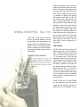
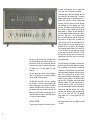
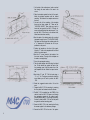
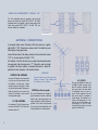
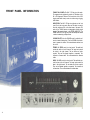
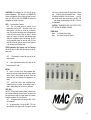
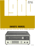
MAC 1700
STEREO RECEIVER
OWNER'S MANUAL
To insure your enjoyment please read and carefully follow these instructions. The time spent will make It possible
for you to enjoy thousands of hours of musical enjoyment.
If you are in a hurry read page 4 first. This gives you a
brief outline of what each control and indicator does.
Reading time for this manual is 30 minutes. This is time
well spent.
GENERAL DESCRIPTION
CONTENTS
1
SPECIFICATIONS
3
IF YOU ARE IN A HURRY
4
CABINET INSTALLATION
5
INSTALLATION-CONNECTIONS
7
COMPLETE SYSTEM HOOK-UP
9
BLOCK DIAGRAM
10
FRONT PANEL INFORMATION
12
BALANCING YOUR SYSTEM
15
ENJOYING YOUR SYSTEM
GUARANTEE
16
Cover
GENERAL DESCRIPTION
MAC 1700
The MAC 1700 is a stereo receiver. There are three
easy to use top notch stereo components in one small
convenient package. A solid state preamplifier, a solid
state power amplifier, and an FM MPX stereo tuner are
combined to give you the best performance possible.
The result is a compact, easy to use stereo instrument.
A stereo instrument that brings you the best in all types
of stereo listening.
A loudness control allows you to listen to music at low
listening levels and still hear the full rich sound of music.
There is a filter which lets you minimize noise and rumble
from program sources. A tape monitor switch lets you
monitor recordings in progress. But the prime function
of a preamplifier is to reproduce records and tapes
with full accuracy and sonic realism. Your MAC 1700
does recreate music from records and tapes with a
degree of accuracy thought impossible a few short
years ago. Records and tapes are made with the bass
frequencies cut and the highs boosted. This allows
more musical information to be put on the record or
tape. The MAC 1700 reintroduces the bass and the
highs following accurate and definite standards. Your
records and tapes sound alive and thrilling when you
hear them through your MAC 1700. Sixteen silicon
planar transistors are used in the preamplifier. Silicon
planar transistors are used because of their high
thermal stability, low noise, and superior high frequency response.
POWER AMPLIFIER
Your MAC 1700 delivers 40 watts of power with both
channels operating. This is 40 watts of steady state
power. Your MAC 1700 delivers 40 watts of power
hours on end. Distortion at 40 watts is less than ¼ of
1 % at any frequency from 30 to 20,000 cps. These
measurements are made by testing sine wave power.
A sine wave signal is fed into the amplifier at a voltage
sufficient to drive the amplifier at rated power output.
Then distortion is measured at full rated power with
both channels operating into an impedance of 8 ohms.
Distortion must be less than ¼ of 1 % from 30 to
20,000 cps. Only then is your MAC 1700 ready for
you. At less than full power distortion becomes so small
it can be measured by only the most sophisticated
laboratory instruments. Only Mclntosh gives you this
kind of performance.
The MAC 1700 gives you a 2.5 microvolt FM stereo
tuner. This sensitive tuner brings you clear, noise-free
reception from distant stations. The tuner section is a
superb product of pride of craftsmanship. In a tuner
1
the power output transistors due to a speaker short
circuit, open circuit, or incorrect low impedance.
each wire must be placed correctly, each lead must be
the precise length and each capacitor must be in an
exact position. So each wire, each capacitor, each lead
is checked and rechecked for maximum performance.
This assures you of the best possible FM stereo
reception.
The tuner section uses six tubes and two transistors.
Tubes as RF amplifiers still give maximum sensitivity
with the greatest overload protection.
The MPX section of the MAC 1 700 uses 2 transistors
and two tubes. In test after test this particular MPX
section out-performed all other designs. The channel
separation of the MPX section is better than the channel separation found with most phono cartridges. The
distortion of the MPX section is less than what the FCC
requires FM stations to maintain. You will hear all there
is to hear from stereo broadcasts.
2
All transistors have a safe power dissipation area. This
area is called the "safe operating area." If a transistor
dissipates power beyond its "safe operating area" it
destroys itself. Your MAC 1700 has a power output
monitoring circuit that prevents the output transistors
from exceeding their "safe operating area." When
your MAC 1700 operates normally the power monitoring circuit has no effect on signals going through the
power amplifier. If, however, the power dissipation in
the output transistors becomes excessive due to speaker
short circuit, open circuit, or a very low impedance
load, the monitor transistors sense this through sampling devices in the output circuit. The monitor transistors restrict the drive to the output transistors. The
restricting operation of the power monitoring circuit is
immediate for any input signal or load combination.
This arrangement assures complete circuit reliability for
all load conditions. The monitoring circuit provides
an extra margin of protection for your MAC 1 700. The
monitoring circuit prevents failure of the power output
transistors due to short circuit, open circuit, or incorrect
low impedance load.
The power transistors are mounted on oversized anodized heat sinks. The heat sinks assure a law temperature for operation of the transistors. If temperatures
increase due to a shorted speaker, or restricted ventilation then an automatic temperature switch turns off your
MAC 1700. The switch will turn your MAC 1700 on
again when the temperature has decreased to a value
suitable for normal operation. This additional feature
gives your MAC 1700 reliability under the most extreme
operating conditions. The power transistors used in
the output section of your MAC 1700 are selected for
their high power dissipation capability, wide frequency
response, and large "safe operating area." In addition, each power transistor is given four separate tests
before it is put in your MAC 1700. This additional
testing assures you of full rated power from 30 to
20,000 cps.
SPECIAL FEATURES
Now sit back and relax with the knowledge you have
A power output monitoring circuit prevents failure of
"THE BEST."
TECHNICAL FEATURES AND SPECIFICATIONS FOR MAC 1700
FM TUNER SECTION:
AMPLIFIER SECTION:
USEABLE SENSITIVITY (at 100% Modulation: 2.5 µV
[I.H.F. Standards)
POWER OUTPUT:
40 watts RMS continuous per channel with both channels operating simultaneously into 4 ohm or 8 ohm
loads.
80 watts RMS continuous monophonic.
30 watts RMS continuous per channel with both channels operating simultaneously into 16 ohm loads.
60 watts RMS continuous monophonic.
SIGNAL TO NOISE AND HUM RATIO: 65db.
HARMONIC DISTORTION: Mono, less than . 5 %
Stereo, less than . 8 %
DRIFT: Less than 25KC
FREQUENCY RESPONSE: Flat from 20 cps to 20KC
with standard 75 µ second de-emphasis and 19KC
pilot frequency filter.
CAPTURE RATIO: Better than 2.0db.
IMAGE REJECTION: Better than 60db.
STEREO MULTIPLEX SEPARATION: Better than 30db
at 1KC.
SPECIAL FEATURES:
A)
Automatic stereo switching.
B)
Muting; IF injected circuit with at least 5 0 d b
quieting between stations.
C) Antenna inputs for 3 0 0 ohm balanced (for twin
lead) and 75 ohm unbalanced (for coaxial cable).
D)
Nuvistor RF amplifier, Nuvistor mixer.
E)
Four stages of IF amplification, with AGC used
to insure limiting occurs only in the limiter stages.
F)
Two limiter stages used for exceptional capture
ratio and smooth muting operation.
G) Multiplex filter and SCA filter, to suppress 19KC
and 38KC signal components at least 4 0 d b below program and to suppress 67KC SCA by 6 0 d b .
H)
Noise rejecting logic circuit used to activate
MPX stereo light and automatic stereo switching
on 19KC stereo pilot only.
I)
D'Arsonval tuning meter for accurate center of
channel tuning.
J)
Flywheel tuning for ease of operation and precise tuning.
HARMONIC DISTORTION: Less than 0.25% at rated
power output from 30 cps to 20KC with both channels operating.
INTERMODULATION DISTORTION: Less than 0.25%
for any combination of frequencies from 30 cps to
20KC if instantaneous peak power is 80 watts per
channel or less into 4 or 8 ohm loads and 60 watts
per channel or less into 16 ohm loads with both
channels operating.
FREQUENCY RANGE: At rated output both channels:
± 0.5db 20 cycles through 20,000 cycles.
+ 0, - 3db 10 cycles through 80,000 cycles.
OUTPUT IMPEDANCE: 4 ohms, 8 ohms, 16 ohms, no
impedance switching required.
INTERNAL IMPEDANCE DAMPING: Less than .04
ohms; damping factor greater than 100.
INPUT SENSITIVITY AND IMPEDANCE: Auxiliary,
Tape, Tuner, and Tape Monitor; 300 MV, 250K
ohms.
BASS CONTROLS: ± 1 8db at 20 cycles, with friction
clutch for independent adjustment for each channel.
TREBLE CONTROLS: ± 1 8 d b at 20,000 cycles with
friction clutch for independent adjustment of each
channel.
TAPE MONITOR SWITCH: Normal or Tape Monitor,
indicator lamp lights in "Monitor" position.
SPEAKER SWITCH: Speakers ON or OFF for headphone listening.
FILTER: Flat or 5,000 cycle and 60 cycle cutoff at 12db
per octave.
LOUDNESS SWITCH: Normal or compensated.
HEADPHONE JACK: For low impedance stereo headphones.
INPUT SELECTOR: 6 positions; AUX, TAPE, TUNER,
PHONO 1, PHONO 2, TAPE HD.
MODE SELECTOR: Two positions; Mono-Stereo
SEMICONDUCTOR COMPLEMENT:
Preamplifier 16 Silicon Transistors
Power Amplifier 1 8 Silicon Transistors
12 Diodes
FM TUNER
8 Tubes, 4 Transistors, 1 0 Diodes
Power Supply 8 Rectifiers
1 Zener Diode, 1 Transistor
POWER REQUIREMENTS: 1 1 7 volts, AC, 50/60 cycles,
70-270 watts
PHONO 1 AND PHONO 2: 2.4 MV, 47,000 ohms.
TAPE HEAD: 2.4 MV, ½ megohm.
MECHANICAL SPECIFICATIONS:
TOTAL NOISE (Including Power Amplifier):
High Level Inputs: 75db below rated output.
Low Level Inputs: 76db below 10 MV input; equivalent to less than 1.5 microvolts at input.
SIZE: Front panel, 16 inches wide by 5½ inches high;
Chassis, 15 inches wide by 51/8 inches high by 14½
inches deep, including connectors. Clearance in front
of mounting panel including knobs, 1 ½ inches.
POWER AMPLIFIER: 90db below rated output.
WEIGHT: 34 pounds net, 47 pounds in
TAPE OUTPUT: Tuner 1.5 volts, other inputs 300 MV at
rated sensitivity, 1.3 volts with 1 0 MV at phono input.
shipping carton.
FINISH: Front Panel, Anodized gold and black.
3
1 Input Selector . . . Aux . . . for any device connected to the AUX input on the back, TAPE
. . . listen to playback from a tape recorder.
FM AUTO , . . listen to FM Stereo or Mono
broadcast automatically . . . Phono I and Phono
2 for phonograph records. TAPE HD . . . listen
to a tape player that hasn't any electronics.
2
Tune for center of black area.
3 Adjust to desired volume. Power off. Turns the
system on off.
4 Tuning . . . select desired station.
5 Treble . . . modifies high frequency sounds. Set
to your taste.
6 Bass . . . modifies low frequency sounds. Set to
your taste.
7 Headphone . . . to connect a set of low impedance stereo headphones.
8 Loud . . . use this switch to compensate for low
volume listening and still hear full frequency
range.
9 Filter In . reduces high frequency noise such
as record surface noise and reduces low frequency noise such as turntable rumble.
10 Muting In . . . eliminates interstation noise.
Muting Out . . . use to receive weak stations.
11 Tape Mon . . . monitor position used to monitor
a recording when used with a tape recorder
with separate playback and record heads.
MUST BE IN OUT POSITION FOR NORMAL
LISTENING.
12 Stereo . . . Mono . . . Set to stereo for all stereo
program material. Mono position for all mono
material.
13 Balance . . . to make one speaker louder than
the other. Permits you to adjust for unequal
sound caused by room acoustics or program
material.
14 Will light only on stations broadcasting MPX
stereo.
4
CABINET INSTALLATION
The MAC 1700 can be installed in furniture cabinets, or custom
built installations. If the unit is to be used on a shelf or table
top, mount it in the attractive MAC
15 WO
cabinet.
Allow sufficient cabinet space for air circulation. Minimum
internal cabinet dimensions should be
5
13 /8
inches deep, and
4¼
15 7 / 16
inches wide,
inches high. The back of the
cabinet should be left as open as possible for ventilation.
Proper ventilation will insure your receiver a long trouble free
life. A fan to circulate the air will further increase the life of
your receiver.
The MAC 1 700 installs easily from the front of the cabinet into
a panel cutout. Front panels of any thickness can be used.
Four screws into the bottom of the MAC 1700 through the
mounting shelf hold the unit firmly in place. Due to the weight
of the MAC 1700 we recommend the unit rest on a wooden
shelf of at least ½" thickness. Unless the MAC 1 700 is adequately held in place vertical mounting should not be attempted. If vertical mounting is used a fan delivering 50
cubic feet per minute must be used.
Since the MAC 1700 must rest on a shelf, locate the cutout
from the back of the panel. A template to help you make
mounting easy is in the packet that contains the owners manual.
5
1 On the back of the cabinet panel, scribe a vertical
line through the exact center of the area to be
cut out.
2 Place the template against the back of the panel.
Match the template centerline with the scribed
centerline. The bottom of the template must rest on
the shelf.
3 On each side of the centerline of the template
there are two holes marked l l B . " These are the
"LOCATING HOLES." These holes are used to
locate the front panel of the MAC 1 700 with reference to the shelf behind the cabinet panel. To insure the MAC 1700 will rest on the cabinet shelf,
follow these instructions carefully.
4 Mark the back of the cabinet panel with a pointed
instrument through the two " B " LOCATING HOLES.
Drill these two holes through the cabinet panel with
a 3/16" diameter drill. Be certain the drill is perpendicular to the panel.
5 Position the template on the front of the panel.
Align the " C " holes in the template with the drilled
holes in the cabinet panel.
6 Mark the " A " corner cutouts in the template. Join
the corner markers. The edge of the template can
be used as a straight edge.
7 Cut out the rectangular opening.
8 Take the shelf template and fold along the dotted
line. Put the dotted line against the back of the
front mounting panel. Align the center line of the
shelf template with the scribed front panel centerline.
9 Mark holes " A " and "B." Drill the holes using a
¼" to ½" bit. The larger you make the holes the
more latitude you will have to position the MAC
1700.
10 Scribe the suggested cutout outline. Cut out the
area.
11 Prepare the MAC 1700 for mounting by removing
the four plastic feet fastened under the chassis.
12 The MAC 1700 is installed from the FRONT of the
cabinet. Insert the MAC 1700 power cord through
the rectangular opening of the cabinet panel.
Carefully slide the MAC 1 700 through the opening.
Continue to slide the MAC 1 700 until its front panel
is against the cabinet mounting panel.
13 Secure the MAC 1700 to the mounting shelf using
the screws supplied in the hardware package.
14 Connect the MAC 1700 to the rest of the system.
6
INSTALLATION
CONNECTIONS TO YOUR MAC 17OO
CONNECTING THE PHONO 1 POSITION for your main record player
Connect the "left" channel to the "L" input of PH 1. Connect
the "right" channel to the l l R" input of PH 1. If your record
player has a ground wire connect the ground wire to GND.
CONNECTING THE PHONO 2 POSITION
Phono 2 position can be used if two record players are used in
a system. Connect the "left" channel to the " L " input of PH 2.
Connect the "right" channel to the "R" input of PH 2.
CONNECTING TAPE PLAYER (no preamplifier in tape player)
Use this position only for a tape deck with no electronics. Connect the "left" channel to the " L " input of TAPE HD. Connect
the "right" channel to the "R" input of TAPE HD.
CONNECTING A TAPE RECORDER or TAPE PLAYER with BUILT-IN ELECTRONICS
Connect the "left" channel of the tape player or tape recorder
to the "L" channel TAPE MONITOR input. Connect the "right"
channel of the tape player or tape recorder to the "R" channel
TAPE MONITOR input.
CONNECTING A TAPE RECORDER WITH THREE HEADS
Connect the tape outputs of the MAC 1700 to the high level
inputs on the tape recorder. This will make it possible for you to
record from the MAC 1 700. Connect the tape recorder outputs
to the TAPE MON inputs on the MAC 1 700. Use TAPE MON . . .
In for listening to pre-recorded tapes as well as to monitor.
CONNECTING A TAPE RECORDER TO RECORD FROM THE MAC 1700
Connect the TAPE OUTPUTS of the MAC 1700 to the high level
inputs on the tape recorder.
7
CONNECTING LOUDSPEAKERS TO THE MAC 1700
The "Left" loudspeaker wires are connected to the two center
screws on the barrier strip marked "LEFT OUTPUT". The "Right"
loudspeaker wires are connected to the two center screws on the
barrier strip marked "RIGHT OUTPUT". The MAC 1700 automatically matches the impedance.
ANTENNA CONNECTIONS
A convenient flexible indoor FM dipole (300 ohm) antenna is supplied
with the MAC 1 700. This antenna is easy to install. It is suitable for good
FM reception in high signal areas.
Connect the two leads of the dipole antenna to the two terminals marked
" 3 0 0 " on the back panel of the MAC 1 700.
The flexibility of the thick flat wire lets you easily locate the dipole behind
the equipment. Open the dipole into a "T." Extend the arms as straight
as possible. The dipole antenna is somewhat directional. It should be
positioned for best reception of the desired stations.
OUTDOOR FM ANTENNA
An outdoor FM antenna is recommended.
It will give you the best reception under
all conditions. In fringe areas, a highly
directional antenna used with a rotator
will give the finest possible FM reception.
Rotate the antenna until it points in the
direction of the station or until it receives
the best possible signal.
75 OHM ANTENNA
An unbalanced 75 ohm FM antenna can
be used with the MAC 1700. Use the two
terminals marked 75.
8
IMPORTANT
Keep the dipole away from large metal
objects or surfaces. They interfere with
the efficiency of the antenna.
MUTING (on the rear panel)
This control determines the strength of
signal necessary for a station to be heard
with the tuner in the muting position. The
muting threshold is carefully adjusted to
optimum at the factory using precision
test instrument. Casual adjustment of the
muting threshold is not recommended.
AC OUTLETS
There are two BLACK AC outlets and
one RED AC outlet. The power to the
black AC outlets is controlled by the
front panel switch. Use these outlets
for accessories such as a tape recorder. The red receptacle is on at all
times and is used for a turntable or
record changer. The turntable is protected by this arrangement. It is necessary to turn off the turntable or record changer by its own AC switch.
Connect the AC cord from your record
player to the RED outlet.
9
10
Having completed the installation of your MAC 1 700 a
new world of musical enjoyment is yours. The following
section gives you a detailed explanation of all the controls
and their functions. It will tell you how to adjust
your MAC 1700 for maximum enjoyment.
Customer Service
McINTOSH AUDIO COMPANY
2 Chambers Street
Binghamton, New York 13903
11
FRONT PANEL INFORMATION
TUNING DIAL SCALES—The MAC 1700 has two dial scales.
The megacycle scale indicates the position of FM stations in the
88 to 108 megacycle FM band. The linear division of the 0-100
logging scale makes it easy to return to a station using a logging
scale number.
INDICATORS—The MAC 1700 has two indicators on the front
panel. One is the tuning meter. When an FM station is correctly
tuned the indicator will be in the black area of the meter. The
action of the TUNING indicator is independent of station signal
strength. The second indicator is the STEREO INDICATOR. The
STEREO INDICATOR will light only when the dial pointer crosses
a station broadcasting multiplex stereo.
VOLUME ON-OFF—Use the VOLUME control to adjust the volume to a desired listening level. Turn the VOLUME control clockwise to increase the volume. Full counterclockwise rotation turns
the unit off.
TREBLE—The TREBLE control is a dual control. The small knob
controls the treble in the left channel. The large knob controls
the treble in the right channel. The two knobs are friction
coupled. They can be adjusted together or separately. Turn
clockwise to increase treble. Turn counterclockwise to decrease
treble.
BASS—The BASS control is a dual control. The small knob controls the bass in the left channel. The large knob controls the
bass in the right channel. The two knobs are friction coupled.
They can be adjusted together or separately. Turn clockwise to
increase bass. Turn counterclockwise to decrease bass.
12
HEADPHONE—The headphone jack is for use with low impedance headphones.
With the switch in the SPEAKER OFF
position the loudspeakers will turn off when you insert your headphone jack. With the switch in the SPEAKER ON position the
loudspeakers will remain in the system.
LOUD . . . An abbreviation of loudness
OUT . . . This is the normal position for moderate to loud
listening levels. Use the LOUD . . . IN position to listen to low
listening levels. It will allow you to hear the full frequency
range. With the volume turned down there is an apparent loss
of bass and treble response. When the volume is low the
human ear's response to bass and treble decreases more
rapidly than its response to notes in the mid-range. The LOUD
control automatically boosts the bass and treble. With the
switch IN the bass and treble are heard in correct proportion
to the mid-range at low listening levels.
onto the tape at the record head. The signal follows a difficult
path . . . the tape is played by the playback head . . . through
the playback preamplifier in the tape recorder . . . out of the
tape recorder into the tape monitor inputs on the MAC 1700
. . . then through the power amplifier of the MAC 1 700 and to
the loudspeakers.
CAUTION: IF THE MONITOR LIGHT IS ON SWITCH TO THE
OUT POSITION FOR NORMAL LISTENING.
STEREO MON.
Stereo . . . for all normal stereo listening.
Mono . . . for all normal monophonic listening.
FILTER (Combination High Frequency and Low Frequency)
Use the filter switch to reduce both high frequency and low frequency noise.
OUT . . . Filter disconnect for normal flat cycles and low frequency response.
IN . . . reduce high frequencies above 5,000 cycles and low
frequencies below 50 cycles.
MUTING
IN . . . turns on the muting circuit. Muting suppresses background hiss and noise usually heard when tuning between
stations. Weak or distant stations that cannot override the
background noise and interference are suppressed by the
muting.
OUT . . . turns off the muting to allow conventional tuning.
Interstation noise will be present. Use this setting to listen to
weak or distant stations that have noise or interference.
TAPE MON.
The MAC 1700 tape switch makes it possible to instantly compare recorded material with the source signal. Tape jacks on the
back panel accept a signal from a tape recorder with a monitor
head and preamplifier. Add light information.
OUT . . . the program source is fed through the MAC 1 700 to
the loudspeakers.
IN . . . the program source is fed from the MAC 1 700 to the
tape output jacks to the tape recorder. The signal is recorded
13
BALANCE
Use the MAC 1700 BALANCE control to balance
unequal volume in the left and right channels.
Right . . . turning the control to the right accents the right channel by reducing the left
channel output.
Left . . . turning the control to left accents the
left channel by reducing the right channel
output.
INPUT SELECTOR
Select any one of six program sources with this switch.
FM AUTO . . . Use this position to listen to all
FM broadcasts. The tuner will automatically
switch to stereo on all stations broadcasting
PHONO 1 ...connects the MAC 1700 for
stereo and monophonic operation of records.
stereo. The tuner will return to mono operation
PHONO 2 . . . Some as PHONO 1.
when you tune in a station broadcasting mono.
TAPE: . . . Any self-contained tape recorder
TAPE HD . . . A tape deck that does not contain its own playback preamplifier is connected to the MAC 1700 through the TAPE
HD position.
(one with built-in playback electronics.)
AUX . . . any auxiliary service requiring flat
amplification, such as a television set, or tape
recorders.
14
NOTE: OWNERS OF TAPE RECORDERS WITH
SEPARATE RECORD AND PLAYBACK HEADS
USE THE TAPE MONITOR POSITION TO
PLAY BACK PRE-RECORDED TAPES.
SETTING YOUR CONTROLS...
a stereo system
The performance and enjoyment of your stereo system increases when the system is balanced. There are two factors in balancing. One is unequal program
loudness on the left and right channels of the program source. The other is basic
system balance. The control marked BALANCE on the MAC 1700 is used to correct both of these problems.
First balance the system. There are many things which affect the balance of
your system: room acoustics, furniture placement, room shape, small differences
in loudspeakers, etc.
TO BALANCE SYSTEM
1 Set the stereo mono switch to M O N O .
2 Play a familiar recording.
3 Turn the balance control to the 1 2 o'clock position.
ADJUSTING PHASE
1 Set the M O N O STEREO switch to M O N O .
4 While the program is playing, stand in the center of the two
loudspeakers. Listen to see if there is a difference in loudness
from either speaker. The sound should come from a point midway between the speakers. If it does not, turn the control toward the speaker that is not as loud as the other. Do this until
you find the point where the sound comes from the mid-point
between the speakers. If it is impossible to get the sound to
come from the mid-point go on to ADJUSTING PHASE. After
you have adjusted the phase you can start the balancing procedure over again.
2 Stand about 10 feet in front of and mid way between your
loudspeakers. The sound should appear to be directly in front
of you. Have someone switch the leads on one speaker. Be sure
to switch the leads on ONE speaker only. If the sound is not
directly in front of you reverse the leads on one loudspeaker.
When the sound comes from the mid-point between the
speakers they are in phase.
15
YOUR SYSTEM
LISTENING TO A STEREO RECORD
1 Turn the INPUT SELECTOR to PHONO 1 or PHONO 2, whichever is connected to the record player you wish to hear.
2 Set the MONO STEREO switch to STEREO.
3 Adjust the VOLUME control to the desired volume.
LISTENING TO MONOPHONIC RECORDS
1 Turn the INPUT SELECTOR TO PHONO 1, or PHONO 2, whichever is connected to the record player you wish to hear.
2 Turn the STEREO MONO switch to MONO.
3 Adjust the VOLUME control to the desired volume.
LISTENING TO TAPE DECKS
1 Turn the INPUT SELECTOR to TAPE HD.
2 Turn the STEREO MONO switch to STEREO. If a mono tape,
turn the balance control to the side you want to hear.
3 Adjust the VOLUME control to the desired volume.
LISTENING TO A STEREO TAPE RECORDER
WITH ITS OWN PLAYBACK PREAMPLIFIER
A stereo tope recorder with its own playback preamplifier should
be plugged in the AUX INPUT . . . NOT THE TAPE HD. INPUT.
LISTENING TO A STEREO TAPE RECORDER
The AUX input is used1 Turn the INPUT SELECTOR TO AUX.
2 Switch the STEREO MONO switch to STEREO or MONO depending on the program on the tape.
3 Adjust the VOLUME control to the desired volume.
USING A TAPE RECORDER WITH THREE HEADS
AND SEPARATE PLAYBACK PREAMPLIFIER
To listen to tapes connect your tape recorder to the TAPE MON
inputs on the rear of the MAC 1700.
1 Switch TAPE MON to "IN."
7 Switch the STEREO MONO switch to STEREO MONO depend
ing on the program on the tape.
3 Adjust the VOLUME control to the desired volume.
MONITORING WHILE RECORDING
16
To monitor while recording your tape recorder must have separate record and playback heads as well as separate playback
preamplifiers. The TAPE MONO switch lets you monitor the quality
of tape recording made from the MAC 1700 during the process
of recording. When the TAPE MONO switch is in the IN position
it will play the sound from the tape as it passes the playback
head, a moment after it is recorded. The recording process continues as usual. When the switch is in the OUT position normal
program from the source is heard.
BE122003
038-210
Your MAC 1700 stereo receiver will give you many years of
pleasant and satisfactory performance. If you have any questions
concerning the operation or maintenance of this receiver please contact:
CUSTOMER SERVICE
Mclntosh Audio Company
2 Chambers Street
Binghamton, New York 13903
Our telephone number is 723-3512
The area code is 607
GUARANTEE
Mclntosh Audio Company guarantees this equipment to perform
as advertised. We also guarantee the mechanical and electrical
workmanship and components of this equipment to be free of
defects for a period of 90 days from date of purchase. This guarantee does not extend to components damaged by improper use
nor does it extend to damage incurred during transportation to and
from Mclntosh Audio Company.
TWO YEAR FACTORY SERVICE CONTRACT
An application for a Free Two Year Factory Service Contract is
included in the packet with this manual. The Free Two Year Factory
Service Contract will be issued by Mclntosh Audio Company upon
receipt of this completely filled out registration form. The terms of
this contract are defined in the Two Year Factory Service Contract.
If this application is not mailed to Mclntosh Audio Company, only
the service offered under the standard 90 day guarantee will apply
to this equipment.
TAKE ADVANTAGE OF 2 YEARS OF FREE FACTORY
SERVICE BY FILLING IN THE APPLICATION NOW
Precision craftsmanship and painstaking attention to finest accuracies make the MAC
1 700 meet high standards.
MCINTOSH AUDIO COMPANY
2 Chambers St., Binghamton, N.Y.
MADE IN U.S.A.
Phone-Area Code 607-723-3512
Design subject to change without notice.