1
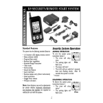
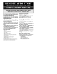
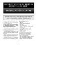
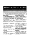
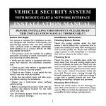
K9 SECURITY AND
REMOTE START SYSTEM
INSTALLATION MANUAL
BEFORE INSTALLING THIS PRODUCT PLEASE READ
THIS INSTALLATION MANUAL THOROUGHLY!!
ITEMS SUPPLIED WITH
THE SYSTEM :
This system is intended for installation on
vehicles equipped with automatic transmissions
and electronic fuel injection only!
• Main unit
• 3-button, LCD remote transmitter
• Plug In LED
• Plug in program switch
• Harness kit with 2 heavy duty fuse holders
• Hood Pin switch
• Extended range transceiver module
• BWS-410 Piezo Audible Beeper
• PDLM-3 Power door lock relay module
• Owner’s manual
DO NOT INSTALL THIS SYSTEM INTO A
MANUAL TRANSMISSION VEHICLE AS IT COULD
RESULT IN SERIOUS INJURY OR DEATH.
• This product must be installed by qualified
personnel according to these instructions and
and observing all safety features.
• The system should be placed into the valet
mode when parked inside a garage or being left
for service.
• Always notify service personnel that the
vehicle is equipped with a Remote Starter.
• Only start the vehicle in a well ventilated
area. Do not use in a closed garage or indoors.
1
Before you begin the installation:
High-Current Wire Connections:
• Verify that the vehicle is equipped with
electronic fuel injection.
• RED WIRE #1 -Main power input; using the
supplied inline fuse holder, connect directly to
the vehicle’s battery or alternate power source
with a minimum 30 Amp supply.
• Verify that the vehicle is equipped with an
automatic transmission.
• RED WIRE #2 - Secondary power input; using
the supplied inline fuse holder, connect directly
to the vehicle’s battery or alternate power
source with a minimum 30 Amp supply.
• Verify that the vehicle starts and idles
properly before you start the installation.
• Always use a multi-meter when verifying
vehicle wiring.
Note: If not connecting directly to the vehicle’s
battery, it is recommended to use separate
power sources (minimum 30 Amp each) for each
red power wire.
Remote Start Installation Notes:
The system senses the vehicle’s successful start
using one of the following methods:
1. Current sense
2. Tachometer sense
3. Spark or Coil Wire sense
If the Current Sense feature of the system does
not allow proper operation, the tachometer
sense/spark sense wire may be used, or an
optional vacuum switch can be installed.
• BROWN WIRE - Second ignition output;
connect to the wire that switches +12V and
does not drop out during cranking.
• YELLOW WIRE - Main ignition output;
connect to the main ignition wire that switches
+12 V and does not drop out during cranking.
• ORANGE WIRE - Main accessory output;
This provides +12V output to heater and/or air
conditioning system. Some cars may have more
than one accessory wire. In these vehicles add a
relay(s) to power the extra accessory wire(s).
To use the tach sense/spark sense wire, set dip
switch #4 to the off position. Connect the gray
wire directly to the vehicle’s tach wire or extend
it into the engine compartment and wrap it
several times around a spark plug or coil wire.
• PURPLE WIRE - Starter output; connect to
the vehicle’s starter wire.
In situations were a tach wire is unavailable or
does not allow proper operation, an optional
vacuum switch can be installed. The vacuum
switch is designed to be placed in line with one of
the vehicle’s vacuum hoses and provide a ground
output (N/C) until the engine is started. To use
the vacuum switch, set dip switch #2 to the off
position. Connect the yellow wire (3-pin red
connector) to one terminal of the vacuum switch
and connect the other terminal to ground.
Main Harness:
• WHITE WIRE - Parking light output (+).
Connect to the wire that switches to +12V
when the parking lights are turned on. If the
vehicle’s parking light circuit exceeds 10 amps a
relay is required. For vehicle’s with independent
left and right parking light circuits, the parking
2
light wires must be connected using diodes to
keep the circuits separate.
shows ground when the door is open.
• BLUE WIRE - Hood switch input wire (-).
Connect this wire to the hood pin switch, this
will prevent the vehicle from remote starting if
the hood is opened. This is a safety input and
must be connected on all installations.
• RED WIRE - +12V battery input.
• BROWN WIRE - Siren wire output (+).
Connect to the siren’s red wire. Connect the
siren’s black wire to ground.
• VIOLET WIRE - Positive door trigger (+).
Connect to the door switch circuit wire that
shows +12V when the door is open. This type
of door circuit is usually found on Ford vehicles.
• BLACK WIRE - Ground input (-). Connect to
a solid chassis ground that is clean and free of
paint or dirt.
• ORANGE WIRE - Armed Output and
Ground When Running Output (-). Connect to
a relay for starter defeat and starter anti-grind
protection. (See installation diagrams). The
ORANGE wire functions as a dual-purpose wire.
It provides a ground when the unit is armed to
activate a starter disable relay (using a starter
disable relay also provides starter anti-grind
protection). It also provides a ground when the
remote start is engaged to activate an optional
factory security bypass module. When the Stopand-Go mode is engaged, the output will turn on
and remain active even after pressing the brake
pedal. Although the remote start shuts down
when the brake pedal is pressed, the output will
remain on until the ignition key is turned off.
• YELLOW WIRE - Brake switch input wire.
Connect this wire to the brake switch wire that
provides +12V when the brake pedal is pressed.
This is a safety input and must be connected
on all installations.
Plug in Connectors:
3-Pin White Door Lock Connector: Plug-in
connector port for door lock harness or
optional door lock relay module (PDLM-3).
• BLUE WIRE - negative unlock output (-).
• RED WIRE - constant +12V low current
output (+) for relay modules, or inverters.
100mA relay trigger only. Do NOT use as a
power source for door lock relays.
• GREEN WIRE - negative lock output (-).
• GRAY WIRE - Tach/Spark sense wire. If the
current sensing feature does not allow desired
operation, connect the GRAY wire directly to
the vehicle’s tach wire or negative fuel injector
wire, and set dip switch #4 to OFF. If the tach
wire is not accessible, wrap the GRAY wire
around a spark plug wire or coil wire several
times and secure with electrical tape.
3-Pin Red Connector: Plug-in connector port
for optional features harness.
• GREEN/BLACK WIRE - Pin 13 on K9 Module.
Connect to a relay for optional trunk release etc.
2-Pin Red Connector: Plug-in connector port
for LED. Mount LED in an area where it may be
easily seen from either side of the vehicle.
• GREEN WIRE - Negative door trigger (-).
Connect to the door switch circuit wire that
2-Pin Blue Connector: Plug-in connector port
for program/service switch. Mount program
3
switch in an area that is easily accessible from the
driver’s position.
To exit valet mode:
1. Turn ignition to the on position.
2. Within 5 seconds press and hold program
switch for approximately 2 seconds.
• The LED will turn off.
5-Pin Antenna Connector: Plug-in connector
port for extended range receiver. Plug harness
into 5-pin connector, route cable up pillar post,
place double sided tape on flat side of receiver
module and place in corner of windshield.
Adding or Deleting Remote Controls
When you enter the code learning mode, the
system will learn new remotes and automatically
delete all other remotes that were previously
operating the system.
Dip Switch Settings
Make sure to set all dip switches in proper
position prior to mounting the module.
NOTE: You must code all desired remotes at
this time.The BWFM200 can learn a maximum
of two transmitters.
To enter Code Learning Mode:
1. Turn ignition key on, off, on, off, and leave
on within 5 seconds.
LED will flicker and parking lights will flash
once.
2. Press and hold program switch for 2
seconds.
3. LED will flicker and parking lights will flash.
The siren will give a series of chirps (as
long as arming chirps are on).
4. Release the program switch.
5. Program all desired remotes by pressing
button #1 on each of the transmitters.
The siren will chirp after the system has
learned each remote control (as long as
arming chirps are on).
6. Turn ignition key off.
Remotes are now programmed to the
system.
Dip Switch #1: Diesel Mode
On = Standard mode
Off = Diesel mode - Ignition turns on for 1213 seconds prior to cranking the starter
(to allow glow plugs to warm up).
Dip Switch #2: Vacuum switch
On = Current sense or tach/spark sense
Off = Vacuum switch sense
Dip Switch #3: Starter cranking time
On = Standard crank time
Off = Extended crank time (auto adjusts)
Dip Switch #4: Tach/Spark sense
On = Current sense
Off = Tach/Spark sense
Valet Mode
When the Valet mode is activated, the vehicle
will not start using the remote, but keyless
entry functions will still operate.
To enter valet mode:
1. Turn ignition to the on position.
2. Within 5 seconds, press and hold
program switch for approximately 2
seconds.
• The LED will light solid.
• Parking lights will flash once.
• The siren will chirp once.
4
SECURITY/REMOTE START WIRING DIAGRAM
LOCK(-)
BLUE
GREEN/BLACK
TRUNK OUTPUT (-)
RED
GREEN
SHOCK
SENSOR
PLUG
SWITCH
+12V
LED
UNLOCK(-)
RF RECEIVER
WHITE
PARKING LIGHT OUTPUT (+)
RED
+12V INPUT
DIP SWITCH SETTINGS
Default settings from
factory are ON
BROWN
SIREN OUTPUT(+)
BLACK
GROUND INPUT
2
3
4
WIRING HARNESS
1
1. ON = Normal operation
OFF = Diesel mode - ignition will turn ON
several seconds before starting vehicle.
2. ON = Normal operation
OFF = Vacuum switch mode - reads YELLOW wire
(3-pin accessory plug) for optional vacuum switch
3. ON = Normal operation
OFF = Extend cranking time - automatically adjusted
4. ON = Dip switch #2 selection (normal/vacuum)
OFF = Tach/Spark sense - reads GRAY tach/spark
sense wire.
ORANGE
TACH/SPARK SENSE (-)
GREEN
DOOR TRIGGER (-)
BLUE
VIOLET
YELLOW
VIOLET
#1
ORANGE
#2
YELLOW
#3
CONNECTORS
BROWN
#4
#5
RED
#6
RED
COLD START ACTIVATION
Automatically starts engine every 1 or 2 hrs. for 24 hrs. max.
While pressing brake pedal, push program switch then
press transmitter button 2. The parking lights will flash
5 times and remain on. Engine will start and run for 30
seconds to confirm activation, then shut down. Once
activated the engine will start automatically and run
for the preset run time.
COLD START DEACTIVATION
The Cold Start feature can be deactivated by stepping
on the brake pedal, turning on the ignition, or remote
starting the vehicle using the transmitter.
5
ARMED OUTPUT/
GROUND WHEN RUNNING (-)
GRAY
HOOD SWITCH INPUT(-)
DOOR TRIGGER (+)
BRAKE SWITCH INPUT (+)
STARTER OUTPUT
ACCESSORY OUTPUT
IGNITION #1 OUTPUT
IGNITION #2 OUTPUT
CONNECT EACH DIRECTLY
TO THE BATTERY (See page 2 )
K9 SECURITY/REMOTE START SYSTEM
Transmitter Operation
Button
DI ARM SVC
UNLOCK
ARM/DISARM/PANIC Button - To arm or disarm the
II
START Button - To start the vehicle, press and hold button
2 for two seconds. To shut down the vehicle, press button 2
and hold for two seconds.
III
Doggie Door - To activate the trunk output, press button 3.
system, press button 1. To activate the panic feature, press
button 1 and hold for three seconds.
O.K.
LOCK
Start
Trunk
Arm
II
Operation
I
+
III
STATUS CHECK - To check current status of the system,
press buttons 2 and 3 together.The current status of the system
will be displayed on the transmitter.
Transmitter Confirmation Indications
ARM
LOCK
Arm The display will flash the ARM
icon and the animated
icon to confirm arming.
Start The display will show the
icon and the icon to indicate
the ignition is turned on and
the engine is going to crank.
When the engine starts and
continues to run, the
icon
will be displayed, the exhaust
icon will flash and the
icon
will rotate.
LOCK
DIS ARM
UNLOCK
Disarm The display will flash the DIS ARM
icon and the animated
to confirm disarming. If the
alarm was triggered while away
the
icon will be displayed.
UNLOCK
Doggie Door The display will flash the
icon opening to confirm
trunk operation.
Door If a door is opened while the
system is armed, the icon
will be displayed, the doorframe
will animate, and the
icon
will be displayed.
Note: Some icons that appear on the transmitter
are reserved for future use and have no functions
at this time.
6
REMOTE START TROUBLESHOOTING
Problem
Unit will not operate.
Probable Cause
Suggested Correction
All power inputs are not Main Inputs (heavy gauge red
wires) and small red wire on
connected to +12V.
main harness must be connected
to +12V.
Keyless Entry features operate System in Service Mode LED is Turn ignition key to on position,
press and hold service switch for
on solid.
but vehicle will not start.
5 seconds.The LED will turn off.
Vehicle will not remote start.
Safety inputs are triggered.
Engine cranks but not long Crank time must be increased.
enough to allow vehicle to start.
Check Brake Switch Input (+)
(Yellow Wire) or Hood Input (-)
(Blue Wire).
Place dip switch #3 to the ON
position.
Vehicle starts without pressing System in Automatic Cold Start To exit press brake pedal or turn
Ignition key on, or activate
Activation Mode.
Remote Transmitter.
remote start using the remote
transmitter.
Vehicle cranks and begins to run, Voltage sense is not working. Wrap the gray wire around a
Use either the spark sense or spark plug wire or connect to
then shuts off.
either the tach wire or a negative
tach sense.
fuel injector wire. Set dip switch
#4 in the OFF position.
Vehicle cranks and begins to run, Vehicle has a factory theft See Bypassing Factory Theft
deterrent system that prevents Deterrent Systems.
then shuts off.
starting w/o key in ignition.
7
SECURITY SYSTEM TROUBLESHOOTING
Problem
Probable Cause
Suggested Correction
Door locks do not lock/unlock
correctly, or action is reversed
Defective GREEN or BLUE wire from
door lock connector plug, GREEN and
BLUE wires reversed, or wrong door
lock wiring diagram used.
Check GREEN and BLUE wires on door
lock connector plug, Check vehicle’s
door lock system for method of
operation. Reverse wiring to door
relays.
PARKING LIGHTS FUNCTIONS
On Solid = Vehicle Remote Starting
Flash 1x = Doors Locked
Flash 2x = Doors Unlocked
Flash 3x = Open Zone Indication (after arming)
Flash 4x = Remote Starting Failed
Flash 5x = Auto Cold Start Engaged
STATUS INDICATOR (LED) FUNCTIONS
On Solid = Valet Mode
Slow Flash = System Armed
Rapid Flash = Passive Arming
Flash 2x = Remote Start
Flash 3x = Stop and Go Mode
Flash 4x = Cold Start Mode
PDLM 3
NEGATIVE PULSE DOOR LOCK SYSTEM
Power Door Lock
Module Instructions
WHITE
N/C
DOOR
GREEN
L
BLUE
1. Plug the LONG harness into the door lock and
alarm modules.
BROWN
VIOLET
U
RELAY
MODULE
N/C
SWITCH
GROUND
2. Plug the 5-wire harness into the door lock module.
REVERSE POLARITY FACTORY DOOR LOCK SYSTEM
3. Wire all 5 wires to appropriate door lock wires.
(See schematic below)
WHITE
DOOR SWITCH
GREEN
BLUE
L
BROWN
U
X X
CUT
X X
VIOLET FUSED
12V+
Color Code for PDLM 3
• Violet- (87) Polarity select wire
ADDING ACTUATORS
WHITE
• Brown- (87a) Unlock switch wire
GREEN
• Blue- (30) Unlock motor wire
BLUE
• Green- (30) Lock motor wire
VIOLET
BROWN
FUSED 12V+
• White- (87a) Lock switch wire
MERCEDES (VACUUM SYSTEM) DIP SWITCH TO #1 TO OFF
SWITCH
CUT
X
POSITIVE PULSE DOOR LOCK SYSTEM
WHITE
N/C
GREEN
BROWN
VIOLET
WHITE
DOOR
U
N/C
SWITCH
N/C
GREEN
L
BLUE
X
CONTROL
MODULE
87
87a
85
86
30
BLUE
RELAY
MODULE
BROWN
VIOLET
FUSED 12V+
FUSED 12V+
8
© 2001, DAVID LEVY COMPANY, INC.
K9SECURITY, 07/01 Rev. 1