1
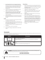
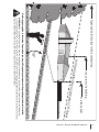
Operator’s Manual
Triple Rear Bagger — 19A40002100
WARNING
READ AND FOLLOW ALL SAFETY RULES AND INSTRUCTIONS IN THIS MANUAL
BEFORE ATTEMPTING TO OPERATE THIS MACHINE.
FAILURE TO COMPLY WITH THESE INSTRUCTIONS MAY RESULT IN PERSONAL INJURY.
CUB CADET LLC, P.O. BOX 361131 CLEVELAND, OHIO 44136-0019
Printed In USA
Form No. 769-04626C
(February 24, 2010)
1
To The Owner
Thank You
Thank you for purchasing a bagging attachment manufactured
by Cub Cadet. It was carefully engineered to provide excellent
performance when properly operated and maintained.
Please read this entire manual prior to operating the equipment.
It instructs you how to safely and easily set up, operate and
maintain your equipment. Please be sure that you, and any
other persons who will operate the machine, carefully follow the
recommended safety practices at all times. Failure to do so could
result in personal injury or property damage.
If you have any problems or questions concerning this
equipment, phone your local Cub Cadet dealer or contact us
directly. Cub Cadet’s Customer Support telephone numbers,
website address and mailing address can be found on this page.
We want to ensure your complete satisfaction at all times.
Throughout this manual, all references to right and left side of the
machine are observed from the operating position.
All information in this manual is relative to the most recent
product information available at the time of printing. Review this
manual frequently to familiarize yourself with the equipment,
its features and operation. Please be aware that this Operator’s
Manual may cover a range of product specifications for various
models. Characteristics and features discussed and/or illustrated
in this manual may not be applicable to all models. Cub Cadet
reserves the right to change product specifications, designs and
equipment without notice and without incurring obligation.
Table of Contents
Safe Operation Practices......................................... 3
Carton Contents & Hardware Packs....................... 6
Assembly & Installation........................................... 8
Operation.................................................................15
Parts List...................................................................16
Warranty...................................................Back Cover
Record Product Information
Model Number
Before setting up and operating your new equipment, please
locate the model plate and record the information in the area
provided to the right. You can locate the model plate by looking
on the outside of the bagger cover. The model plate contains
the unit’s model and serial numbers. This information will be
necessary, should you seek technical support via our web site,
Customer Support Department, or with a local authorized service
dealer.
Serial Number
Customer Support
If you have difficulty assembling this product or have any questions regarding the controls, operation, or maintenance of
this machine, you can seek help from the experts. Choose from the options below:
2
◊
Visit us on the web at www.cubcadet.com
◊
Call a Customer Support Representative at (800) 965-4CUB
◊
Locate your nearest Cub Cadet Dealer at (877) 282-8684
◊
Write us at Cub Cadet • P.O. Box 361131 • Cleveland, OH • 44136-0019
Important Safe Operation Practices
2
WARNING! This symbol points out important safety instructions which, if not followed,
could endanger the personal safety and/or property of yourself and others. Read and follow
all instructions in this manual before attempting to operate this machine. Failure to comply
with these instructions may result in personal injury.
When you see this symbol. HEED ITS WARNING!
DANGER! This attachment was built to be used according to the safe operation practices in
this manual. Carelessness or error on the part of the operator can result in serious injury.
Mowers are capable of amputating hands and feet and throwing objects. Failure to observe
the following safety instructions as well as the instructions provided with your mower, could
result in serious injury or death.
General Operation
1.
2.
3.
4.
5.
Read, understand, and follow all instructions on your
equipment and in their manuals before attempting to
assemble and operate. Keep this manual in a safe place for
future and regular reference and for ordering replacement
parts.
To help avoid blade contact or a thrown object injury, keep
bystanders, helpers, children and pets at least 75 feet from
the mower while it is in operation. Stop machine if anyone
enters the area.
Thoroughly inspect the area where the equipment is to be
used. Remove all stones, sticks, wire, bones, toys, and other
foreign objects which could be picked up and thrown by
the blade(s). Thrown objects can cause serious personal
injury.
Always wear safety glasses or safety goggles during
operation and while performing an adjustment or repair
to protect your eyes. Thrown objects which ricochet can
cause serious injury to the eyes.
Do not operate the mower without the discharge cover
or entire grass catcher in its proper place. A missing
or damaged discharge cover or grass bag attachment
component may result in thrown objects or blade contact
injuries.
6.
Do not put hands or feet near rotating parts or under the
cutting deck. Contact with the blade(s) can amputate
hands and feet.
7.
Shut off mower’s engine and wait for blades to come to
a complete stop before unclogging mower’s discharge
opening or bagger parts.
8.
Slow down before turning. Operate the machine smoothly.
Avoid erratic operation and excessive speed. Be aware
that a grass catcher attachment can affect the handling
characteristics of your mower.
9.
Disengage blade(s), set parking brake, stop engine and wait
until the blade(s) come to a complete stop before opening
bagger attachment’s top cover, removing grass catcher,
emptying grass, unclogging chute, removing any grass or
debris, or making any adjustments.
10.
Never leave a running machine unattended. Always turn
off blade(s), place transmission in neutral, set parking
brake, stop engine and remove key before dismounting.
11.
Your machine is designed to cut normal residential grass of
a height no more than 10”. Do not attempt to mow through
unusually tall, dry grass (e.g., pasture) or piles of dry leaves.
Dry grass or leaves may contact the engine exhaust and/
or build up on the mower deck presenting a potential fire
hazard.
12.
If situations occur which are not covered in this manual, use
care and good judgment. Contact your customer service
representative for assistance.
Slope Operation
Slopes are a major factor related to loss of control and tip-over
accidents which can result in severe injury or death. Attachments
can also affect the stability of the machine. All slopes require
extra caution.
For your safety, use the slope gauge included as part of this
manual to estimate the angle of slopes before operating this
machine on a sloped or hilly area. If the slope is greater than 10
degrees as shown on the slope gauge, do not operate the mower
with the grass bag attachment installed on that area or serious
injury could result.
Do:
1.
Mow up and down slopes, not across. Exercise extreme
caution when changing direction on slopes.
2.
Watch for holes, ruts, bumps, rocks, or other hidden
objects. Uneven terrain could overturn the machine. Tall
grass can hide obstacles.
3
3.
Use slow speed. Choose a low enough speed setting so
that you will not have to stop or shift while on the slope.
Tires may lose traction on slopes even though the brakes
are functioning properly. Always keep machine in gear
when going down slopes to take advantage of engine
braking action.
4.
Follow the manufacturer’s recommendations for wheel
weights or counterweights to improve stability.
5.
Keep all movement on the slopes slow and gradual. Do
not make sudden changes in speed or direction. Rapid
engagement or braking could cause the front of the
machine to lift and rapidly flip over backwards which could
cause serious injury.
6.
Avoid starting or stopping on a slope. If tires lose traction,
disengage the blade(s) and proceed slowly straight down
the slope.
General Service
1.
Before cleaning, repairing, or inspecting, make certain the
blade(s) and all moving parts have stopped. Disconnect the
spark plug wire and ground against the engine to prevent
unintended starting.
2.
Keep all nuts, bolts, and screws tight to be sure the
equipment is in safe working condition.
3.
Never tamper with your mower’s safety interlock system
or other safety devices. Check their proper operation
regularly.
4.
Never attempt to make adjustments or repairs while the
mower’s engine is running.
5.
Grass catcher components and the discharge cover are
subject to wear and damage which could expose moving
parts or allow objects to be thrown. For safety protection,
frequently check components and replace immediately
with original equipment manufacturer’s (O.E.M.) parts only,
listed in this manual. Use of parts which do not meet the
original equipment specifications may lead to improper
performance and compromise safety!
6.
Maintain or replace safety and instruction labels, as
necessary.
Do Not:
1.
Do not turn on slopes unless necessary; then, turn slowly
and gradually downhill, if possible.
2.
Do not mow near drop-offs, ditches or embankments. The
mower could suddenly turn over if a wheel is over the edge
of a cliff, ditch, or if an edge caves in.
3.
Do not try to stabilize the machine by putting your foot on
the ground.
4.
Do not use a grass catcher on steep slopes.
5.
Do not mow on wet grass. Reduced traction could cause
sliding.
Safety Symbols
This table depicts and describes safety symbols that may appear on this product. Read, understand, and follow all instructions on the
machine before attempting to assemble and operate.
Symbol
Description
READ THE OPERATOR’S MANUAL(S)
Read, understand, and follow all instructions in the manual(s) before attempting to
assemble and operate
STOP
Turn off the engine before opening the bagger cover.
Warning! Your Responsibility—Restrict the use of this power machine to persons who read, understand and
follow the warnings and instructions in this manual and on the machine.
SAVE THESE INSTRUCTIONS!
4
Section 2 — Important Safe Operation Practices
(r
e
p
r
e
s
e
nts a
1
0
°
s
l
ope)
or a fence post
or a corner of a building...
e
lon
g
d
o
t
t
e
d lin
Fold a
Sight and hold this level with a vertical tree...
10°
Use this page as a guide to determine slopes where you may safely operate your mower with a grass bag attachment installed.
WARNING! Do not operate your lawn mower with a bagger attachment on inclines with a slope in excess of 10 degrees
(a rise of approximately 1-3⁄4 feet every 10 feet). A riding mower with a bagger attachment could overturn and cause serious
injury. Operate riding mowers up and down slopes, never across the face of slopes.
5
Section 2 — Important Safe Operation Practices
3
Contents of Carton
Before beginning installation, remove all parts from the carton to make sure everything is present. Carton contents are listed below
and shown in Fig. 3-1. Three hardware packs are included in this kit and are detailed on the following page.
•
Hinge Cover Pin
•
Hitch Bracket Kit (3 Pcs. & Hardware Pack)
•
Bagging Blades (6 blades total)
•
Chute Tube Extension
•
Two Deck Baffles
•
Discharge Chute Elbow
•
Chute Discharge Plate
•
Hitch Support
•
Chute Stop Bracket
•
Grass Catcher Cover Screen
•
Upright Support
•
Grass Catcher Cover
•
Bag Support Assembly
•
Three Grass Bag Assemblies
•
Three Hardware Packs (Detailed & illustrated on next page)
•
Upper Chute Tube
•
Upper Chute Support
Hitch Bracket Kit
(3 Pcs. & Hardware)
6
Figure 3-1
CONTENTS OF HARDWARE PACK
This grass collector kit is shipped with three loose hardware packs enclosed and one set of hardware included in the mounting bracket kit.
Please check your hardware packs against the illustrations below. The quantities for each item is listed in parenthesis.
Hardware included with 689-00096
Hardware Pack 689-00163
(3)
(1)
(1)
712-04065
710-3008
(3)
710-0276
(2)
712-04064
712-04063
(2)
Hardware Pack 689-00087
(1)
(4)
726-3046
(3)
710-3008
(4)
711-0309A
710-3015
(1)
712-04063
(2)
714-0117
710-04484
723-0476
(1)
(3)
710-3168
Section 3 — Contents of Carton
7
3
Assembly & Installation
NOTE: References to left, right, front and rear of the tractor are
from the operator’s position, unless otherwise stated.
•
Before assembly, place the tractor on a firm, level surface,
disengage the PTO, stop the tractor engine and set the
parking brake.
•
For convenience, pivot the seat forward and leave it in
that position until the grass collector is fully mounted and
assembled.
Assemble Mounting Brackets
To assemble the bagger mounting assembly, locate the
mounting assembly pack and follow these steps:
1.
Attach the two hitch side brackets to the universal rear
attachment bracket using four hex bolts and flange lock
nuts. With the hooks on the hitch side brackets pointing
down, the tabs on the hitch plates should be pointing
upwards. See Fig. 4-1.
Side View
Figure 4-2
Assembling The Support Assembly
Locate the upright support bracket and the bag support
assembly. Assemble it by following these steps:
2.
1.
Lay the bag support assembly topside down with the
mounting bracket portion facing upwards.
2.
Insert the notched end of the vertical support bracket into the
bag support assembly, as in Fig. 4-3, and secure with a 5/16-18
carriage bolt and 5/16-18 flange lock nut. See Fig. 4-4.
Figure 4-1
Flip over assembly and mount the hitch support bracket to
the mounting assembly using the hardware found in pack
689-00087. See Fig. 4-2.
Note: It might be easier during the mounting stage to
leave this hardware only finger tight to facilitate lining up
the hitch hole for the clevis pin. You will be instructed to
tighten this hardware later in this manual.
Figure 4-3
8
Note: The clevis pin can be fed down through the hitch
plate and secured underneath with the hairpin clip, or it
may be easier to feed the clevis pin up through the hitch
plate hole and secure with the hairpin clip on the topside.
The latter method may be preferred since it can be easier
to insert the hairpin clip. Either way will work, the decision
should be based on operator preference.
Figure 4-4
Align hole on bracket
with hole on tractor
Mount Assembly on Tractor
Install mounting assembly on tractor as follows:
1.
Place the hooked ends of the mounting assembly over
the shoulder bolts, as in Fig. 4-5, on the tractor and line up
the hitch support bracket center hole with the hole on the
tractor’s hitch.
Figure 4-6
Note: If you decided to leave the hitch support only
finger tight during the assembly process, tighten all of the
hardware securely at this time.
3.
Install the bagger hanger assembly onto the mounting
assembly on the tractor by hooking it over the hitch plate
in the center, lining up the center mounting hole as seen in
Fig. 4-7.
Figure 4-5
2.
Install the clevis pin from hardware pack 689-00087 into the
tractor’s hitch and secure with a hairpin clip inserted into the
top hole, which is the hole located closest to the head of the
clevis pin. See Fig. 4-6.
Mounting Hole
Figure 4-7
4.
Secure the hanger assembly to the mounting assembly
using a 5/16” bolt and flange nut provided. See Fig. 4-7.
Section 4 — Assembly & Installation
9
Assembling Remaining Bagger Components
Now that the mounting brackets are assembled and are in place
on the tractor, follow these steps to assemble the remaining
bagger components.
1.
Snap the plastic upper chute support in place by first
clipping the side portion onto the bagger support rail (1)
with the edge of the snap feature aligned with the red line,
as seen in the inset of Fig. 4-8.
2.
Snap the front side of the chute support to the rail (2), as
shown in Fig. 4-8.
2
1
Make sure screen sits under the cover’s lip
5.
Figure 4-10
Install the bagger cover onto the bag support assembly, as
seen in Fig. 4-11. The plastic cover goes inside of the two
mounting tabs.
Figure 4-8
3.
Install the bagger screen into the bagger cover by first
inserting the end closest to the center into the cutout
mounting hole, as in Fig. 4-9. Make sure to feed the screen
under the lip, as in Fig. 4-10.
Cover mounts in
between these
two tabs
Figure 4-11
Figure 4-9
4.
10
Clip in the other side by flexing the screen and pushing it
down into the provided cutout hole. See Fig. 4-10.
Section 4 — Assembly & Installation
6.
Slide the hinge pin into the hole located on the mounting
tab, as in Fig. 4-12. Use the cut-out window (See inset in
Fig. 4-12) to line up the hinge pin on the other side and
push pin all the way in until it reaches the end-stop. At this
point the pin clips into place and is secured by a tab in the
bagger cover. See Fig. 4-13.
7.
Open Hood by pushing in on the rear, right-side tab with
your right hand, as seen in 1 of Fig. 4-14, and lifting the cover
with your left hand in the center rear of the bagger cover, 2.
2
1
Figure 4-14
8.
Figure 4-12
Install the bag assemblies onto the bag support brackets
by inserting the front edge in first, as seen in Fig. 4-15, and
setting the back edge down until it fits into the assembly.
1
2
Figure 4-13
Figure 4-15
Section 4 — Assembly & Installation
11
Attaching Blades
6.
warning! Always protect your hands while
servicing blades by wearing heavy work gloves or
using heavy rags.
NOTE: High-lift bagging blades are included in the grass-catcher
kit. Replace the blades with these new blades and save the
existing blades as replacements or to reinstall on the blade
spindles when not using the bagger kit.
Move the wood block to either the left or right blade for
stabilization and remove and replace the center blade so
that side of the blade with part number faces the ground
when the mower is in the operating position.
NOTE: Save the three blades you just removed to use as
replacements or to reinstall on the blade spindles when not
using the bagger kit.
Installing the Deck Baffle
1.
Remove cutting deck from beneath the tractor following
instructions for Deck Removal in operator’s manual of the
tractor. Gently flip the deck over to expose its underside.
Note: If the deck is still flipped upside down with the blades
exposed, it may be easiest to flip the deck back over to complete the
following installation of the deck baffle and chute stop bracket.
2.
Place a block of wood between the center deck housing
baffle and the cutting blade to act as a stabilizer. See
Fig. 4-16.
1.
Remove two of the self-tapping deck screws on the front
right side of your deck.
2.
Install the front deck baffle using the hardware pack 68900163 included with this bagger kit. See Fig. 4-17.
Wood Block
Hex Flange Nut
Note: This bagger kit includes two deck baffles, one baffle is
for the 50” deck and the other is for a 54” deck. Based on the
deck that you have, install one of the following baffles using the
directed hardware. The baffles may be identified by looking at
the parts list on Page 16:
•
50” Mowing Deck, install deck baffle Part No. 703-05783
using two 710-3015 1/4-20 hex bolts and 712-04064 1/4-20
flange lock nuts.
•
54” Mowing Deck, install deck baffle Part No. 703-06018A
using two 710-04484 self-tap hex bolts.
Hex Nut
Spindle Assembly
Figure 4-16
3.
Use a 15/16” wrench to remove the hex flange nut that
secures the blades to the blade spindle assemblies. See
Fig. 4-16.
WARNING! The hex flange nut has a right-handed
thread pattern. Do not attempt to force the nut in
wrong direction; it may damage the nut and create a
safety hazard.
4.
Place a new blade on each spindle so that side of the blade
with part number faces the ground when the mower is in
the operating position.
Note: This bagger kit includes two sets of blades, one set is
for the 50” deck and the other is for the 54” deck. Based on
the deck that you have, install one of the following blade
sets. The blades can be identified by the part number
stamped on each blade:
5.
12
• 50” Mowing Deck, install Part No. 742-04056C
• 54” Mowing Deck, install Part No. 742-0679
Secure with the hex flange nut removed earlier. Use a
torque wrench to tighten the hex flange nut between 70 to
90 foot-pounds.
Section 4 — Assembly & Installation
Deck Baffle
Hex Bolt
50” Deck
54” Deck
Figure 4-17
Installing the Chute Discharge Plate
1.
Remove the discharge chute by removing the two flange
lock nuts securing it.
NOTE: An extra carriage bolt and lock nut have been
supplied in your bagger kit in hardware pack 689-00163.
You may replace the old hardware for the chute stop
bracket with this new hardware, or save for later use.
2.
With a hammer, lightly tap the bolts out. Discard the bolts
and flange lock nuts.
NOTE: This chute stop bracket may stay on the unit even
when the bagger is not being used.
3.
Install the chute discharge plate to the bottom side of the
deck opening, as seen in Fig. 4-18, using two carriage bolts
supplied in hardware pack 689-00163.
4.
Figure 4-18
Replace the discharge chute and secure with two flange
lock nuts included in the hardware pack 689-00163.
5.
Securely tighten the hardware at this time.
Installing the Chute Strap on the Discharge Chute
Secure the strap to the chute with the hex screw (710-3015) and
flange nut (712-04064) provided In Hardware pack 689-00163.
See Fig. 20.
Figure 4-20
Attaching Chute Stop Bracket
Installing the Discharge Chute
1.
1.
Reinstall the cutting deck to the tractor reversing the
instructions for Deck Removal in operator’s manual of the
tractor.
2.
Raise the deck to its highest position.
3.
Raise the chute deflector (A in Fig. 4-21) on the deck and
hold it while you position the discharge chute over the
chute opening.
4.
Insert the hinge pin of the discharge chute into the tube on
the chute stop bracket. See B in Fig. 4-21.
Remove the carriage bolt and lock nut holding the chute stop
to the deck. See the left Inset of Fig. 4-19. Save the hardware.
A
C
Figure 4-19
2.
Install the new chute stop bracket, from the loose parts, at
the same position on the deck. See the right Inset of Fig.
4-19. Secure with the hardware removed earlier.
B
Figure 4-21
Section 4 — Assembly & Installation
13
5.
Rotate the chute around the deck so that its front edge fits
snugly into the deck opening. Lower the chute deflector
slowly (C in Fig. 4-21).
6.
Attach the retainer strap on the discharge chute to the
retainer clip on the deck. Refer to Fig. 4-22.
8.
Peel the backing off of the self-adhesive foam strip (72104388) that has been included with your grass collector.
Apply it to the upper chute, flush against the flange as
shown in Fig. 24.
Flange
Figure 4-22
Note: For the chute elbow to be properly installed, the bottom
edge must fall below the bottom of the deck opening and the
tab on top of the elbow should rest above the deck opening.
7.
Install the chute adapter onto the chute elbow by lining up
the tabs and sliding the adapter over the chute elbow, as in
Fig. 4-23. Secure the chute adapter by installing two ratchet
clips (726-3046), included in hardware pack 689-00163, into
the holes provided.
Figure 4-24
9.
With the bagger cover open, install the upper chute over
the chute adapter, and rest the top so that the chute
support sits in the upper chute groove. See Fig. 4-25.
Note: Make sure to align the upper chute with the ridges
on the bagger support bracket, as shown in the inset of
Fig. 4-25.
Figure 4-25
Figure 4-23
14
Section 4 — Assembly & Installation
5
Operation
Bagger Usage
3.
NOTE: When all of the grass bags are full, place the tractor on a
firm, level surface, disengage the PTO, turn the tractor engine off
and set the parking brake.
1.
Flip Seat up.
2.
Lift up grass bag cover by pushing in on the rear, right-side
tab with your right hand, as seen in 1 of Fig. 5-1, and lifting
the cover with your left hand in the center rear of the bagger
cover, 2. Do not remove the chute tube assembly from the
tractor.
Remove the grass bags, as shown in Fig. 5-2, by lifting each
bag up (1) and moving the bags away from the bag support
assembly (2).
2
1
2
Figure 5-2
1
Figure 5-1
4.
Empty the grass clippings at a proper disposal sight, use
the handle at the bottom of each grass bag. Holding the
bag firmly, empty the contents
5.
Replace the grass bags in the reverse order and in the same
orientation in which they were removed, close lid, flip
down seat, restart your tractor and resume cutting your
grass.
15
19A40002100 Parts List
A
17
2
5
18
16
12
19
22
8
4
20
21
13
32
11
9
35
12
5
6
A
10
3
12
6
24
6
27
15
24
7
12
30
23
25
34
26
23
21
22
31
14
1
16
28
29
Ref.
Part Number
Description
1.
931-04291
Upper Chute Assembly
2.
931-04298
Triple Bagger Cover Assembly
3.
731-06497
Upper Chute Support
4.
731-06504
Bagger Cover Screen
5.
710-0276
Carriage Screw, 5/16-18 x 1.00”
6.
710-3008
Hex Head Screw, 5/16-18 x .75”
7.
711-0309A
Clevis Pin, .62” Dia.
8.
964-04090A
Grass-bag Assembly
9.
683-04498A
Triple Bag Support Assembly
10.
683-04519
Vertical Support Bracket
11.
711-05079
Cover Hinge Pin
12.
712-04063
Flange Lock Nut, 5/16-18
13.
735-0246A
End Plug
14.
631-04493
Discharge Chute Elbow, 50/54” Deck
15.
683-0617A-0637
Chute Stop-Bracket
16.
N/A*
Hitch Bracket, RH
17.
N/A*
Universal Rear Attachment Bracket
18.
N/A*
Hitch Bracket, LH
19.
703-05783-0637
Deck Baffle, 50”
20.
703-06018A-0637
Deck Baffle, 54”
21.
710-3015
Tap Screw, 1/4 - 20 x .750 (50” Deck)
22.
712-04064
Flange Lock Nut, 1/4 - 20 (50” Deck)
23.
710-3168
Carriage Screw, 3/8 - 16 x 1.00”
24.
712-04065
Flange Lock Nut, 3/8 - 16
25.
714-0117
Internal Cotter Pin, .148 x 3.00
26.
726-3046
Ratchet Clip, .250
27.
731-06611
Bagger Chute Adapter, 7 In.
28.
942-0679
Blade, 18.50 Lg., High Lift
29.
742-04056C-0637
Blade, 17.90 Lg., Star Bagging
30.
783-05887-0637
Universal Bracket Support, RT-99/LT-5
31.
723-0476
Chute Strap
32.
710-04484
Tap Screw, 5/16-18 x .750 (54” Deck)
33.
689-00101
Mounting Bracket Kit (Incl. Ref. 16-18)
34.
783-06694
Discharge Chute Plate
35.
721-04388
Adhesive Foam Strip
*Order Reference No. 33
17
Notes
18
19
CUB CADET LLC
MANUFACTURER’S LIMITED WARRANTY
FOR SEPARATELY SOLD ATTACHMENTS AND ACCESSORIES
IMPORTANT: To obtain warranty coverage owner may be required
to present an original proof of purchase and applicable maintenance
records to the servicing dealer. Please see the operator’s manual for
information on required maintenance and service intervals.
a. Routine maintenance items such as lubricants, filters, blade
sharpening, tune-ups, brake adjustments, clutch adjustments, deck
adjustments, and normal deterioration of the exterior finish due to
use or exposure.
The limited warranty set forth below is given by Cub Cadet LLC with
respect to new merchandise purchased or leased and used in the United
States and/or its territories and possessions, and by MTD Products
Limited with respect to new merchandise purchased or leased and
used in Canada and/or its territories and possessions (either entity
respectively, “Cub Cadet”).
b. Service completed by someone other than an authorized service
dealer.
Cub Cadet warrants this product (excluding its Normal Wear Parts,
as described below) against defects in material and workmanship for
a period of two (2) years commencing on the date of original retail
purchase or lease and will, at its option, repair or replace, free of charge,
any part found to be defective in materials or workmanship.
d. Replacement parts and\or accessories that are not genuine Cub
Cadet parts.
Normal Wear Parts are warranted to be free from defects in material and
workmanship for a period of thirty (30) days from the date of original
purchase or lease. Normal wear parts include, but are not limited to
items such as: belts, blades, blade adapters, grass bags, rider deck
wheels, seats, and tires.
This limited warranty shall only apply if this product has been operated
and maintained in accordance with the Operator’s Manual furnished
with the product, and has not been subject to misuse, abuse, neglect,
accident, improper maintenance, alteration, vandalism, theft, fire, water,
or damage because of other peril or natural disaster. Damage resulting
from the installation or use of any part, accessory or attachment not
approved by Cub Cadet for use with the product(s) covered by this
manual will void your warranty as to any resulting damage. In addition,
Cub Cadet may deny warranty coverage if the hour meter, or any part
thereof, is altered, modified, disconnected or otherwise tampered with.
HOW TO OBTAIN SERVICE: Warranty service is available, WITH PROOF
OF PURCHASE AND APPLICABLE MAINTENANCE RECORDS, through
your local authorized service dealer. To locate the dealer in your area:
In the U.S.A.:
Check your Yellow Pages, or contact Cub Cadet LLC at P.O. Box 361131,
Cleveland, Ohio 44136-0019, call 1-877-282- 8684
or log on to our website at www.cubcadet.com.
In Canada:
Contact MTD Products Limited, Kitchener, ON N2G 4J1, call 1-800-6681238 or log on to our website at www.mtdcanada.com.
Without limiting the foregoing, this limited warranty does not provide
coverage in the following cases:
c. Cub Cadet does not extend any warranty for products sold or
exported outside of the United States and/or Canada, and their
respective possessions and territories, except those sold through
Cub Cadet’s authorized channels of export distribution.
e. Transportation charges and service calls.
f. Commercial or Institutional Use.
There are no implied warranties, including without limitation any
implied warranty of merchantability or fitness for a particular
purpose. No warranties shall apply after the applicable period of
express written warranty above. No other express warranties beyond
those mentioned above, given by any person or entity, including a
dealer or retailer, with respect to any product, shall bind Cub Cadet.
The exclusive remedy is repair or replacement of the product as
set forth above. The terms of this warranty provide the sole and
exclusive remedy arising from the sale and/or lease of the products
covered hereby. Cub Cadet shall not be liable for any incidental or
consequential loss or damage including, without limitation, expenses
incurred for substitute or replacement lawn care services or for
rental expenses to temporarily replace a warranted product.
Some jurisdictions do not allow the exclusion or limitation of incidental
or consequential damages, or limitations on how long an implied
warranty lasts, so the above exclusions or limitations may not apply to
you.
In no event shall recovery of any kind be greater than the amount of the
purchase price of the product sold. Alteration of safety features of the
product shall void this warranty. You assume the risk and liability for
loss, damage, or injury to you and your property and/or to others and
their property arising out of the misuse or inability to use the product.
This limited warranty shall not extend to anyone other than the original
purchaser or to the person for whom it was purchased as a gift.
HOW LOCAL LAWS RELATE TO THIS WARRANTY: This limited warranty
gives you specific legal rights, and you may also have other rights that
vary in different jurisdictions.
Cub Cadet LLC, P.O. BOX 361131 CLEVELAND, OHIO 44136-0019, Phone: 1-877-282-8684
MTD Products Limited, Kitchener, ON N2G 4J1, Phone: 1-800-668-1238
GDOC-100177 REV. A