1
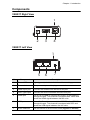
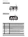
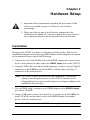
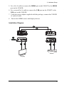
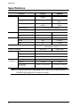
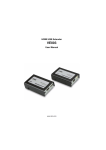
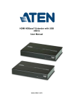
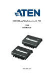
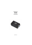
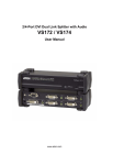
HDMI USB Extender VE803 User Manual www.aten.com VE803 User Manual FCC Information Warning: This is a class A product. In a domestic environment this product may cause radio interference in which case the user may be required to take adequate measures. FEDERAL COMMUNICATIONS COMMISSION INTERFERENCE STATEMENT This equipment has been tested and found to comply with the limits for a Class A digital device, pursuant to Part 15 of the FCC Rules. These limits are designed to provide reasonable protection against harmful interference when the equipment is operated in a commercial environment. This equipment generates, uses, and can radiate radio frequency energy and, if not installed and used in accordance with the instruction manual, may cause harmful interference to radio communications. Operation of this equipment in a residential area is likely to cause harmful interference in which case the user will be required to correct the interference at his own expense. FCC Caution: Any changes or modifications not expressly approved by the party responsible for compliance could void the user's authority to operate this equipment. RoHS This product is RoHS compliant. SJ/T 11364-2006 The following contains information that relates to China. ii VE803 User Manual User Information Online Registration Be sure to register your product at our online support center: International http://eservice.aten.com Telephone Support For telephone support, call this number: International 886-2-8692-6959 China 86-10-5255-0110 Japan 81-3-5615-5811 Korea 82-2-467-6789 North America 1-888-999-ATEN ext 4988 United Kingdom 44-8-4481-58923 User Notice All information, documentation, and specifications contained in this manual are subject to change without prior notification by the manufacturer. The manufacturer makes no representations or warranties, either expressed or implied, with respect to the contents hereof and specifically disclaims any warranties as to merchantability or fitness for any particular purpose. Any of the manufacturer's software described in this manual is sold or licensed as is. Should the programs prove defective following their purchase, the buyer (and not the manufacturer, its distributor, or its dealer), assumes the entire cost of all necessary servicing, repair and any incidental or consequential damages resulting from any defect in the software. The manufacturer of this system is not responsible for any radio and/or TV interference caused by unauthorized modifications to this device. It is the responsibility of the user to correct such interference. The manufacturer is not responsible for any damage incurred in the operation of this system if the correct operational voltage setting was not selected prior to operation. PLEASE VERIFY THAT THE VOLTAGE SETTING IS CORRECT BEFORE USE. iii VE803 User Manual Package Contents Basic Package The basic VE803 package consists of: 1 VE803T HDMI USB Extender 1 VE803R HDMI USB Extender 1 Power Adapter 1 USB cable (1.8 m) 1 Mounting Kit 1 User Instructions* Check to make sure that all the components are present and that nothing got damaged in shipping. If you encounter a problem, contact your dealer. Read this manual thoroughly and follow the installation and operation procedures carefully to prevent any damage to the unit, and/or any of the devices connected to it. * Features may have been added to the VE803 since this manual was published. Please visit our website to download the most up-to-date version. © Copyright 2013 ATEN® International Co., Ltd. Manual Date: 2013-07-10 ATEN and the ATEN logo are registered trademarks of ATEN International Co., Ltd. All rights reserved. All other brand names and trademarks are the registered property of their respective owners. iv VE803 User Manual Contents FCC Information . . . . . . . . . . . . . . . . . . . . . . . . . . . . . . . . . . . . . . . . . . . . . ii RoHS. . . . . . . . . . . . . . . . . . . . . . . . . . . . . . . . . . . . . . . . . . . . . . . . . . . . . . ii SJ/T 11364-2006. . . . . . . . . . . . . . . . . . . . . . . . . . . . . . . . . . . . . . . . . . . . . ii User Information . . . . . . . . . . . . . . . . . . . . . . . . . . . . . . . . . . . . . . . . . . . . .iii Online Registration . . . . . . . . . . . . . . . . . . . . . . . . . . . . . . . . . . . . . . . .iii Telephone Support . . . . . . . . . . . . . . . . . . . . . . . . . . . . . . . . . . . . . . . .iii User Notice . . . . . . . . . . . . . . . . . . . . . . . . . . . . . . . . . . . . . . . . . . . . . .iii Package Contents. . . . . . . . . . . . . . . . . . . . . . . . . . . . . . . . . . . . . . . . . . . iv Basic Package. . . . . . . . . . . . . . . . . . . . . . . . . . . . . . . . . . . . . . . . . . . iv About this Manual . . . . . . . . . . . . . . . . . . . . . . . . . . . . . . . . . . . . . . . . . . . vi Conventions . . . . . . . . . . . . . . . . . . . . . . . . . . . . . . . . . . . . . . . . . . . . . . . vii Product Information. . . . . . . . . . . . . . . . . . . . . . . . . . . . . . . . . . . . . . . . . . vii 1. Introduction Overview . . . . . . . . . . . . . . . . . . . . . . . . . . . . . . . . . . . . . . . . . . . . . . . . . . . 1 Features . . . . . . . . . . . . . . . . . . . . . . . . . . . . . . . . . . . . . . . . . . . . . . . . . . . 2 Requirements . . . . . . . . . . . . . . . . . . . . . . . . . . . . . . . . . . . . . . . . . . . . . . . 3 Source Device . . . . . . . . . . . . . . . . . . . . . . . . . . . . . . . . . . . . . . . . . . . . 3 Display Device. . . . . . . . . . . . . . . . . . . . . . . . . . . . . . . . . . . . . . . . . . . . 3 Cables . . . . . . . . . . . . . . . . . . . . . . . . . . . . . . . . . . . . . . . . . . . . . . . . . . 3 Components . . . . . . . . . . . . . . . . . . . . . . . . . . . . . . . . . . . . . . . . . . . . . . . . 4 VE803T Right View . . . . . . . . . . . . . . . . . . . . . . . . . . . . . . . . . . . . . . . . 4 VE803T Left View . . . . . . . . . . . . . . . . . . . . . . . . . . . . . . . . . . . . . . . . . 4 VE803R Right View . . . . . . . . . . . . . . . . . . . . . . . . . . . . . . . . . . . . . . . . 5 VE803R Left View . . . . . . . . . . . . . . . . . . . . . . . . . . . . . . . . . . . . . . . . . 5 2. Hardware Setup Installation . . . . . . . . . . . . . . . . . . . . . . . . . . . . . . . . . . . . . . . . . . . . . . . . . . 7 3. Basic Operation Overview . . . . . . . . . . . . . . . . . . . . . . . . . . . . . . . . . . . . . . . . . . . . . . . . . . . 9 EDID Switch . . . . . . . . . . . . . . . . . . . . . . . . . . . . . . . . . . . . . . . . . . . . . . . . 9 Equalization Adjustment . . . . . . . . . . . . . . . . . . . . . . . . . . . . . . . . . . . . . . . 9 Appendix Safety Instructions. . . . . . . . . . . . . . . . . . . . . . . . . . . . . . . . . . . . . . . . . . . 10 General . . . . . . . . . . . . . . . . . . . . . . . . . . . . . . . . . . . . . . . . . . . . . . . . 10 Technical Support . . . . . . . . . . . . . . . . . . . . . . . . . . . . . . . . . . . . . . . . . . . 12 International. . . . . . . . . . . . . . . . . . . . . . . . . . . . . . . . . . . . . . . . . . . . . 12 North America . . . . . . . . . . . . . . . . . . . . . . . . . . . . . . . . . . . . . . . . . . . 12 Specifications . . . . . . . . . . . . . . . . . . . . . . . . . . . . . . . . . . . . . . . . . . . . . . 13 Limited Warranty . . . . . . . . . . . . . . . . . . . . . . . . . . . . . . . . . . . . . . . . . . . . 14 v VE803 User Manual About this Manual This User Manual is provided to help you get the most from your system. It covers all aspects of installation, configuration and operation. An overview of the information found in the manual is provided below. Chapter 1, Introduction, introduces you to the VE803 system. Its purpose, features and benefits are presented, and its front and back panel components are described. Chapter 2, Hardware Setup, describes how to set up your installation. All necessary steps to prepare for operation are provided. Chapter 3, Basic Operation, describes how to use the EDID switch and EQ switch to adjust the picture quality. An Appendix, provides specifications and other technical information regarding the VE803. vi VE803 User Manual Conventions This manual uses the following conventions: Monospaced Indicates text that you should key in. [] Indicates keys you should press. For example, [Enter] means to press the Enter key. If keys need to be chorded, they appear together in the same bracket with a plus sign between them: [Ctrl+Alt]. 1. Numbered lists represent procedures with sequential steps. ♦ Bullet lists provide information, but do not involve sequential steps. → Indicates selecting the option (on a menu or dialog box, for example), that comes next. For example, Start → Run means to open the Start menu, and then select Run. Indicates critical information. Product Information For information about all ATEN products and how they can help you connect without limits, visit ATEN on the Web or contact an ATEN Authorized Reseller. Visit ATEN on the Web for a list of locations and telephone numbers: International http://www.aten.com North America http://www.aten-usa.com vii Chapter 1 Introduction Overview The VE803 HDMI USB Extender extends HDMI signals up to 60 meters from the HDMI source using two Cat 5e cables. It is capable of sending 1080i signals up to 60 meters, and 1080p signals up to 40 meters. The VE803 is equipped with USB connectors, which allow you to extend any USB device between the units. The USB feature also provides support for touch panel control, allowing you to control the local HDMI source device from the remote display, or control the remote display through the local unit. The VE803 is ideal for transportation centers, medical facilities, shopping malls or anywhere touch panel control at a kiosk is required. For flexibility and convenience, the VE803 local unit can be powered via the USB cable when connected to an appropriate source device. The VE803 is HDCP compliant, providing an easy and ideal HDMI extender solution for any application. 1 Chapter 1. Introduction Features Uses two Cat 5e cables to connect the local and the remote units Extends 1080p by 40m; extends 1080i by 60m Superior video quality – HDTV resolutions of 480p, 720p, 1080i, 1080p (1920x1080), VGA, SVGA, XGA, SXGA, UXGA and WUXGA (1920x1200) Supports USB touch panels 8-segment Equalization adjustment switch optimizes display quality Supports Dolby True HD and DTS HD Master Audio Built-in 8KV / 15KV ESD protection Transparent USB Support – supports all USB 2.0 full speed device (12 Mbps) USB 2.0 compatible Supports wide screen formats HDMI (3D, Deep Color); HDCP compatible – signaling rates up to 2.25 Gbits Transmitter unit powered via USB cable 2 VE803 User Manual Requirements Source Device The following equipment must be installed on the source device or computer: HDMI Type A output connector(s) Display Device A display device or receiver with an HDMI Type A input connector Cables Use HDMI cables to connect the HDMI source and display device to the VE803T and VE803R Use two Cat 5e cables to connect the VE803T to the VE803R Use standard USB cables with Type A to Type B connectors to connect USB devices Note: Cables are not included in this package. We strongly recommend that you purchase high-quality cables of appropriate length since this will affect the quality of the audio and video display. Contact your dealer to purchase the correct cable sets. Maximum cable distances are as follows: 40 m at 1080p @ 24-bit color depth 60 m at 1080i @ 24-bit color depth 3 Chapter 1. Introduction Components VE803T Right View 1 2 3 4 VE803T Left View 1 5 No. Component 6 7 Description 1 Power LED Lights (green) to indicate that the unit is receiving power. 2 Power Jack The power adapter cable plugs connects here. 3 HDMI Input port Connect the HDMI source device to this port. 4 USB Type B port Connect the source controller device to this port. 5 HDMI port Use a Cat 5e cable to connect the VE803T to the VE803R through this port. This channel is equipped with TMDS and sends the HDMI signal between the two units. 6 USB port Use a Cat 5e cable to connect the VE803T to the VE803R through this port. This channel is equipped with DDC and sends the USB signal between the two units. 7 EDID Selection Use this switch to set the EDID mode (Bypass or Default) . 4 VE803 User Manual VE803R Right View 1 2 3 4 VE803R Left View 1 5 No. Component 6 7 Description 1 LEDs Three LEDs – Power, HDMI, and USB – light (green) when the unit is properly connected to an appropriate source. 2 Power Jack The power adapter cable plugs connects here. 3 HDMI Out Connect the HDMI display to this port. 4 USB Type A port Connect the display device to this port for controlling the source device. 5 HDMI port Use a Cat 5e cable to connect the VE803T to the VE803R through this port. This channel is equipped with DDC and sends the USB signal between the two units. 6 USB port Use a Cat 5e cable to connect the VE803T to the VE803R through this port. This channel is equipped with DDC and sends the USB signal between the two units. 7 EQ Switch This 8-segment switch is used to adjust video quality. 5 Chapter 1. Introduction This Page Intentionally Left Blank 6 Chapter 2 Hardware Setup 1. Important safety information regarding the placement of this device is provided on page 10. Please review it before proceeding. 2. Make sure that the power to all devices connected to the installation are turned off. You must unplug the power cords of any computers that have the Keyboard Power On function. Installation Setting up the VE803 is a matter of plugging in all the cables. Refer to the installation diagram on the next page (the numbers in the diagram correspond to the numbered steps) and do the following: 1. Connect one end of an HDMI cable to the HDMI output port of your source device, and connect the other end to the HDMI Input port on the VE803T. 2. Using the USB cable provided with this package, connect one end (Type B connector) to the USB port on the VE803T, and the other end (Type A connector) to the source device. Note: The VE803T takes its power from this USB port. If the power supply is not enough to power on the VE803T, the unit can be plugged directly to a power outlet using a second power adapter (not supplied in this package). 3. Use an HDMI cable to connect your HDMI display to the HDMI Output port on the VE803R. 4. Using a USB cable, connect one end (Type A connector) to the USB port on the VE803R, and the other end to your HDMI display (or another device, such as a touchscreen). Note: The USB cable for the VE803R is not supplied in this package. 7 2. Hardware Setup 5. Use a Cat 5e cable to connect the HDMI port on the VE803T to the HDMI port on the VE803R. 6. Use a second Cat 5e cable to connect the USB port on the VE803T to the USB port on the VE803R. 7. Using the power adapter supplied with this package, connect the VE803R to a power outlet. 8. Turn on the HDMI source and display devices. Installation Diagram 5 6 VE803R VE803T 7 3 4 1 2 Source Display 8 Chapter 3 Basic Operation Overview This chapter describes the EDID and Equalization (EQ) switch functions to adjust the HDMI display and obtain the best video quality. EDID Switch Extended Display Identification Data (EDID) is a data format that contains a display's basic information and is used to communicate with the video source/ system. In order to deliver the best video format, the VE803 is able to read the EDID information from the display and determine the best video resolution to send to the video source and program its resolution. Use the EDID switch on the VE803T to manually switch EDID modes. There are two EDID modes to choose from: EDID/DDC Bypass- This mode bypasses the use of EDID / DDC, thus allowing the display information to come directly from the HDMI display to the source device, and determine the best resolution. ATEN Default- ATEN’s default EDID setting is sent to the video source to set the display resolution setting for your HDMI display. Equalization Adjustment The 8-segment Equalization (EQ) switch located on the VE803R unit is used to adjust the video quality. Use the EQ switch to adjust the equalization strength in order to improve a flickering or blinking image: 7 = Strongest EQ 0 = Weakest EQ 9 Appendix Safety Instructions General Read all of these instructions. Save them for future reference. Follow all warnings and instructions marked on the device. This product is for indoor use only. Do not place the device on any unstable surface (cart, stand, table, etc.). If the device falls, serious damage will result. Do not use the device near water. Do not place the device near, or over, radiators or heat registers. The device cabinet is provided with slots and openings to allow for adequate ventilation. To ensure reliable operation, and to protect against overheating, these openings must never be blocked or covered. The device should never be placed on a soft surface (bed, sofa, rug, etc.) as this will block its ventilation openings. Likewise, the device should not be placed in a built in enclosure unless adequate ventilation has been provided. Never spill liquid of any kind on the device. Unplug the device from the wall outlet before cleaning. Do not use liquid or aerosol cleaners. Use a damp cloth for cleaning. The device should be operated from the type of power source indicated on the marking label. If you are not sure of the type of power available, consult your dealer or local power company. The device is designed for IT power distribution systems with 230V phase-to-phase voltage. To prevent damage to your installation it is important that all devices are properly grounded. The device is equipped with a 3-wire grounding type plug. This is a safety feature. If you are unable to insert the plug into the outlet, contact your electrician to replace your obsolete outlet. Do not attempt to defeat the purpose of the grounding-type plug. Always follow your local/national wiring codes. Do not allow anything to rest on the power cord or cables. Route the power cord and cables so that they cannot be stepped on or tripped over. 10 Appendix If an extension cord is used with this device make sure that the total of the ampere ratings of all products used on this cord does not exceed the extension cord ampere rating. Make sure that the total of all products plugged into the wall outlet does not exceed 15 amperes. To help protect your system from sudden, transient increases and decreases in electrical power, use a surge suppressor, line conditioner, or un-interruptible power supply (UPS). Position system cables and power cables carefully; Be sure that nothing rests on any cables. Never push objects of any kind into or through cabinet slots. They may touch dangerous voltage points or short out parts resulting in a risk of fire or electrical shock. Do not attempt to service the device yourself. Refer all servicing to qualified service personnel. If the following conditions occur, unplug the device from the wall outlet and bring it to qualified service personnel for repair. The power cord or plug has become damaged or frayed. Liquid has been spilled into the device. The device has been exposed to rain or water. The device has been dropped, or the cabinet has been damaged. The device exhibits a distinct change in performance, indicating a need for service. The device does not operate normally when the operating instructions are followed. Only adjust those controls that are covered in the operating instructions. Improper adjustment of other controls may result in damage that will require extensive work by a qualified technician to repair. 11 Appendix Technical Support International For online technical support – including troubleshooting, documentation, and software updates: http://eservice.aten.com For telephone support, see Telephone Support, page iii: North America Email Support Online Technical Support [email protected] Troubleshooting Documentation Software Updates Telephone Support http://www.aten-usa.com/support 1-888-999-ATEN ext 4988 When you contact us, please have the following information ready beforehand: Product model number, serial number, and date of purchase. Your computer configuration, including operating system, revision level, expansion cards, and software. Any error messages displayed at the time the error occurred. The sequence of operations that led up to the error. Any other information you feel may be of help. 12 Appendix Specifications Connectors Function VE803T VE803R HDMI In 1 x HDMI Type A Female (Black) N/A N/A 1 x HDMI Type A Female (Black) 1 x USB Type B Female (White) 1 x USB Type A Female (White) HDMI Out USB HDMI/USB Port* 2 x RJ-45 Female (Silver) Power Switches EQ Compensation LED Power EDID Selection 1 x 8-position switch 1 x slide switch N/A 1 x Green 1 x Green HDMI N/A 1 x Green USB N/A 1 x Green Video Resolution Power Consumption Environment 1 x DC Jack (Black) N/A 1080p @ 60Hz, at 40m 1080i @ 60Hz, at 60m DC5V; 1W Operating Temp. 0–50ºC Storage Temp Physical Properties DC5V; 3.9W -20–60ºC Humidity 0–80% RH, Non-condensing Housing Metal Weight Dimensions (L x W x H) 0.16kg 0.16kg 7.16 x 3.16 x 2.30 cm 7.16 x 3.16 x 2.30 cm Note: *HDMI/USB Port is equipped with TMDS.DDC and sends the HDMI/USB signal between the two units. 13 Appendix Limited Warranty IN NO EVENT SHALL THE DIRECT VENDOR'S LIABILITY EXCEED THE PRICE PAID FOR THE PRODUCT FROM DIRECT, INDIRECT, SPECIAL, INCIDENTAL, OR CONSEQUENTIAL DAMAGES RESULTING FROM THE USE OF THE PRODUCT, DISK, OR ITS DOCUMENTATION. The direct vendor makes no warranty or representation, expressed, implied, or statutory with respect to the contents or use of this documentation, and especially disclaims its quality, performance, merchantability, or fitness for any particular purpose. The direct vendor also reserves the right to revise or update the device or documentation without obligation to notify any individual or entity of such revisions, or update. For further inquiries, please contact your direct vendor. 14