1
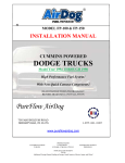
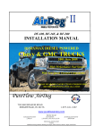
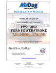
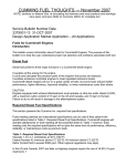
INSTALLATION MANUAL MODEL FP-100 WITH OPTIONAL LOW PRESSURE WARNING LIGHT FOR 24 VALVE CUMMINS® POWERED ® DODGE TRUCKS READ INSTRUCTIONS THOROUGHLY BEFORE BEGINNING INSTALLATION. PUREFLOW® TECHNOLOGIES, INC. 5400 BUSINESS 50 WEST SUITE 8 PROTECTED UNDER US PATENTS 5,355,860; 5,746,184; 6,729,310 and Foreign Patents Issued & Pending (573) 635-0555 VOICE JEFFERSON CITY, MO 65109 FAX (573) 635-0778 Installation Manual PUREFLOW® DIESEL SYSTEM AirDog™ PUREFLOW® DIESEL SYSTEM AirDog MODEL FP-100 Welcome to the PUREFLOW® DIESEL SYSTEM AirDog™ Air/fuel Separation, filtration and delivery system for the diesel engine. The installation of the AirDog™ can be made relatively easy by following the steps outlined in this manual. 1. Inventory the package components completely. Notify PUREFLOW® TECHNOLOGIES, INC. Immediately of any parts missing or damaged. 2. Read the owner’s manual and the installation manual completely. Understand how the system operates and installation recommendations before beginning installation. 3. The installation recommendations contained herein are suggested installation guidelines only. Individual installations may vary. Use good judgment and common sense when installing the AirDog™ If any installation procedure is uncertain, contact PUREFLOW™ TECHNOLOGIES, INC for technical assistance. Please fill out and mail the Product Registration/Warranty Card enclosed with this manual. 2 Installation Manual PUREFLOW® DIESEL SYSTEM AirDog™ TABLE OF CONTENTS Section 1 ........................................... AirDog™ OVERVIEW Section 2 ........................................... Parts List Section 3 ........................................... Safety Guidelines and Warnings Section 4 ........................................... Installation of Mounting Brackets, & AirDog™ Section 5 ........................................... Installation of Fuel Lines Section 6 ........................................... Installation of Electrical Harness Section 7 ........................................... Final Check List 3 Installation Manual PUREFLOW® DIESEL SYSTEM Section 1 AirDog™ OVERVIEW The PUREFLOW™ DIESEL SYSTEM AirDog™ Air/Fuel Separation System is the “missing link” between the fuel tank and the engine for diesel powered equipment. The AirDog™ delivers clean fuel to the engine free of virtually all air/vapor and at a positive flow. Thus, allowing the engine “test cell” performance and efficiency, while in “real world” use. The AirDog™ FP-100 is suitable for all stock and slightly modified 5.9 Cummin's® Diesels. Connecting the AirDog™ to the stock 3 /8" OD (outside diameter) fuel suction tube at the tank is OK. Satisfactory performance and operation from the AirDog™ depends upon proper installation and maintenance. TYPICAL INSTALLATION Fuel Line Return to Tank Dash Plate Indicator Light Fuel Tank Filler Tube Relay Engine Battery Fuel Tank Electrical Harness Fuel Line From Tank Fuel Line to Engine AirDog FP-80 4 Installation Manual PUREFLOW® DIESEL SYSTEM Section 2 AirDog™ AirDog™ PARTS LIST Qty Description Part Number 1 AirDog™ PF100 1 Mounting Bracket 001-3C-0004 1 Installation Manual Optional Indicator Light Assembly Includes: Indicator Light, Dash Plate, Grommet & Pressure Switch 901-04-0001 1 Electrical Harness 5E-2-002 1 Mounting Hdwr Kit, Unit-to-Bracket Image Includes: 4 Il-A20C Socket Head Cap Screws, 1/4-20 x 1-1/4" Lg. Stainless Steel 3 4 3 4 3 2 1J-1-C20SN Bolt, Hex Hd., Grade 8, 3/8-16 x 1-1/4" Lg. 1S-1-ASN Hex Nut, 1/4-20, Stainless Steel 1S-1-CSN Hex Nut 3/8-16 Steel, Nickel Plated 1R-6-ASN Washer, Split-Lock, Helical, #1/4, Stainless Steel 1R-6-CSN Washer, Split-Lock, Helical, #3/8, Steel, Nickel Plated Fuel Fitting, #8 SAE male to 3/8" -NPT 4A-1-01-08-06-B NOTE: Various components and materials discussed in this manual that are marked "(*)" are special to a particular vehicle installation and supplied in a separate kit. 5 6 Installation Manual PUREFLOW™ DIESEL SYSTEM Section 3 AirDog™ Dodge/Cummins 24 Valve Installation Accessory Kit Includes Frame Mounting Bracket with Backup Plate 3/8”-16x4-1/2” Hex Head Bolt 3/8” Lock Nut, 3/8” Flat Washer ½” ID Fuel Line 3/8” Quick Connect Fitting to ½” Pushlock Fitting 90 Degree #8 Flare x ½” ID Hose Barb Fitting #8 Flare (male) x 12 mm fitting w/Washer #8 Flare (female swivel) x ½” Hose Barb Fitting Filler Tube Return Fuel Fitting (1-1/2” OD) w/Hose Clamps 90 Degree #8 Swivel (female) to #8 (male) 12” Cable Ties 6” Cable Ties 1 3 3 20ft. 1 1 1 4 1 3 5 10 SAFETY GUIDELINES AND WARNINGS! IMPORTANT Use diesel fuel compatible thread sealer on all NPT tapered pipe thread fuel fitting connections! IMPORTANT When installing push lock fuel line fittings remember to lubricate the fittings with oil before inserting fittings into the fuel line. NOTE: Proper location of the AirDog™ on the vehicle is essential. Consider hazards presented to the equipment by road debris and the elements. WARNING! Frame rails should not be drilled into or welded upon. CAUTION: Wear safety glasses when operating power tools such as drills and grinders or when using a punch or chisel. CAUTION: Use common sense when routing fuel lines and electrical harnesses. Keep them away from hot exhaust components and/or moving parts. Properly secure lines to prevent chaffing. 7 Installation Manual PUREFLOW® DIESEL SYSTEM Section 4 AirDog™ DODGE/CUMMIN'S 24 VALVE INSTALLATION PROCEDURES Installation of AirDog™ and Bracket to the Truck’s Frame Loose assemble mounting bracket to frame with backing plate using 3/8” x 4 ½” bolts, lock washers, and nuts included in the kit. Position mounting bracket so that its back is adjacent to the rear of the transmission tail shaft (above the transfer case skid plate on 4 x 4’s) to allow ease in changing of the fuel filter. After positioning bracket, properly torque fasteners. STEP 1 3/8-16 x 4 ½ Lg. Figure 1: Image taken on a Dodge 2500 (stock model) 8 Installation Manual PUREFLOW® DIESEL SYSTEM Section 4 AirDog™ Install the two 3/8" NPT x #8 SAE flare fuel fittings into the AirDog™ ports marked "FUEL IN" & "ENGINE". Use diesel compatible thread sealer when installing these fittings. Note: Return fuel fitting comes factory installed to hold pressure regulator in place. Remove fuel filter and water separator from AirDogTM. Adjust AirDogTM to its bracket using 1/4-20 stainless steel socket head screws provided. Attach AirDog™ and bracket to the frame mounting bracket with 3/8-16 Hex head bolts. Secure the entire units, as illustrated. STEP 2 Mount and secure AirDog™ to frame and bracket. This is how your AirDog™ should look like after these procedures have been completed. 9 Installation Manual PUREFLOW® DIESEL SYSTEM Section 5 AirDog™ FUEL LINES THIS SECTION IS APPLICABLE TO STOCK AND SLIGHTLY MODIFIED ENGINES. Fuel Suction Line 5-1 From end of fuel line supplied with attached 'Quick Disconnect' fitting, measure and cut length of line required to connect fuel tank SUCTION port to AirDog™ inlet port marked "Fuel In". 5-2 Install #8 female swivel x 1/2" 'push lock' fitting into other end of fuel line (Ref. 5-1). Fuel Line # 8 Flare Fitting To fuel tank To AirDog™ fuel “in” port Fig. 3 Fuel line installation 5-3 Remove the original fuel suction line from fuel tank by squeezing the tabs on the end of the connector together. Consult factory manual if unsure. Connect the 'New Fuel Line' Quick Connect fitting to fuel tank by pushing the connector onto the tank supply tube until connector seats. Check connection for seating. Fig. 4 10 Installation Manual PUREFLOW® DIESEL SYSTEM Section 5 AirDog™ Fuel Suction Line Cont’d Quick connect Figure 5: Fuel tank To release quick-connect fitting from fuel tank suction tube, firmly push fitting toward the component being serviced while firmly holding the plastic retainer ring into the fitting. While the plastic ring is depressed, pull the fitting assembly from the suction tube. Use care to press the retainer ring squarely into the fitting body. It may be difficult to disconnect the fitting if the retainer is cocked during removal. Note: After removing the factory line check to make sure that the blue plastic retainer was removed with the line. If the blue retainer remained attached to the tank tube, it MUST be removed before the AirDog™ fuel line will connect to the tank tube. 5-4 Connect 'New Fuel Suction Line' swivel end to #8 male flare fitting at AirDog™ port marked 'FUEL IN'. FUEL IN Figure 6: Connecting the AirDog™ to the suction line of the tank 11 Installation Manual PUREFLOW® DIESEL SYSTEM Section 5 AirDog™ Fuel Supply Line 'RETURN TO TANK' FUEL LINE 5-5 Installing fuel 'Return to Tank' assembly in filler tube. Hose Clamp Filler Tube Filler Tube Fuel Return Fitting Fuel Tank Fuel Tank STEP 1. STEP 2. Cut filler tube as illustrated, removing 1½ inches. Loose assemble clamps on each end of filler tube. Insert 'Return To Tank' assembly in filler tube, rotate and position #8 flare fitting. Properly tighten clamps. cut filler tube Figure 7: Installing 'Return to Tank' assembly 12 Installation Manual PUREFLOW® DIESEL SYSTEM Section 5 AirDog™ Fuel Supply Line 5-6 Installing fuel return line. Return Line # 8 Flare Fitting Return to tank Fuel suction line To engine STEP 1. STEP 2. Measure and cut length of 1/2" ID fuel line necessary to connect AirDog™ to 'Return To Tank' assembly in filler tube. Install #8 Swivel x ½ " pushlock fitting into each end of fuel line. Connect fuel line to AirDog™ port marked 'TANK' & #8 flare fitting on 'Return To Tank' filler tube assembly. Properly torque fittings. Figure 8: Connect return fuel line here 13 Installation Manual PUREFLOW® DIESEL SYSTEM Section 5 AirDog™ Fuel Supply Line from AirDog™ To Engine The AirDog™ fuel filter is made of the same Stratapore™ media as the OE filter. For optimum engine performance, it is recommended to by pass the factory filter head when installing the AirDog™ fuel system. 5-7 Remove original factory fuel supply line at the engine by removing the banjo fitting from fuel inlet port in VP44 injector pump or inlet port on Common Rail engine. Install the 12mm x #8 flare fitting supplied with AirDog™ accessory kit into the engine port vacated by the original banjo fitting. Properly torque #8 flare fitting. COMMON RAIL ENGINE – CP3 2003-2004 models VP-44 1998½ -2002 models banjo fitting, fuel inlet port Fuel supply line port Figure 10: Fuel supply line 14 Installation Manual PUREFLOW® DIESEL SYSTEM 5-8 Section 5 AirDog™ Measure and cut length of line required to connect the 'Fuel to Engine' port on AirDog™ to 12mm x #8 flare (Ref. 5-7) on engine fuel inlet port. 1/2” Barb -to- #8 SAE Adapter 1/2 ID Flexible Hose Engine Engine Port Fuel Line Engine Figure 11: Connecting AirDog™ to engine Install 90o x 1/2" hose barb on end to engine. Install straight hose barb on end to AirDog™. Connect 90o fitting to 12mm x #8 flare on engine. Properly route and connect fuel line to AirDog™ fuel port marked 'ENGINE'. IMPORTANT: Properly torque all fuel fittings and connections. Use 'ties' to secure fuel lines to vehicle to prevent chaffing and abrasion 15 Installation Manual PUREFLOW® DIESEL SYSTEM Section 6 AirDog™ WIRING HARNESS The AirDog™ is equipped with a relay controlled wiring harness that connects directly to the battery and is activated by the OE fuel pump connection. Optional "low fuel pressure" warning light is available. 6-1 Connect the RED lead to the POSITIVE (+) post of the driver's side battery. Connect the GREEN lead to the NEGATIVE (-) post of the same battery. 6 - 2 Route the wiring harness to the AirDog™ and connect the 3 pin Deutsch connector to the corresponding connector on the AirDog™. 6 - 3 Secure the relay to the vehicle at either the engine side wheel house or firewall near the steering column. 6 - 4 Disconnect the OE fuel pump lead from the ECM connection (Deutsch, two pin connector). 6 - 5 Connect the AirDog™ 'Relay activation lead' to the OE fuel pump ECM connection. 6 - 6 Optional light kit. Remove 1/8” npt plug located in top of base, below the motor. Screw in pressure switch and tighten. Fasten the two wires from the wire harness to the pressure switch. NOTE: If the optional indicator light is not used, place electrical tape around the 2 indicator light terminals on the wire harness, keeping both spade terminals separate. 6 - 7 Drill a 5/8" hole in firewall approximately 2 inches to the door side of the steering column to allow entry of the Indicator Light harness into the passenger compartment. 6 - 8 Route the Indicator Light harness through the firewall. Install the grommet supplied in kit around wiring harness where it passes through the firewall to prevent chaffing. 6 - 9 Install Indicator Light and Dash Plate in lower left dash area or where desired. Drill an 11/16" hole at the desired location to mount the indicator light assembly. Install the adhesive backed dash plate by removing the backing and matching the corresponding dash plate hole with the 11/16" hole. 6 - 10 Properly assemble the indicator light in the dash plate. Connect the two female connectors on the wiring harness to the spade connectors on the indicator light. BE SURE TO PROPERLY ROUTE AND SECURE THE WIRING HARNESS TO THE VEHICLE. 16 Installation Manual PUREFLOW® DIESEL SYSTEM Section 7 AirDog™ INITIAL START PROCEDURE The AirDog™ is a self priming system, however, to prevent damage to a dry seal and reducing the life expectancy of the system, it is recommended to prefill the water separator with diesel fuel before initial startup. 7-1 Prefill the water separator with diesel fuel. 7-2 Turn the starter key to the on/run position. Note: It may be necessary to momentarily engage the starter in order for the ECM to energize the AirDog™. 7-3 While the AirDog™ is on, bleed the fuel line to the engine by loosening the fuel line connection at the engine fitting. As soon as the line is purged of air and pure fuel is observed, properly tighten the fuel fitting. NOTE: put a rag or shop towel over and around fitting to prevent splatter. Catch all spilled fuel and dispose of properly. RECHECK ALL FUEL FITTINGS FOR LEAKAGE AND PROPERLY TORQUE. BE SURE ALL LINES ARE PROPERLY ROUTED TO PROTECT FROM EXCESSIVE HEAT AND SECURED TO PROTECT FROM CHAFFING AND ABRASION. RECHECK ALL ELECTRICAL LINES, SECURE AS NECESSARY. 7-4 Start engine! NOTE: Should any installation problems arise, please call, toll free 1-877-463-4373, for assistance (Monday – Friday, 8:00 am – 5:00 pm CST). Visit our website at www.pureflowtechnologies.com for updated materials and frequently asked questions. 17