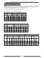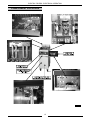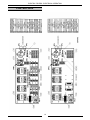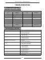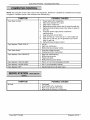
1
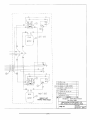
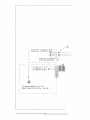
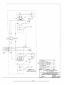
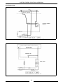
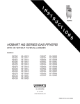
SERVICE MANUAL
FLOOR MODEL
ELECTRIC FRYERS
MODEL
ML
DESCRIPTION
ERD40
114614
15 ½" WIDE
ERD50
114615
15 ½" WIDE
ERD225
114616
15 ½" WIDE
ERD85
114617
21" WIDE
ERC40
114618
15 ½" WIDE
ERC50
114619
15 ½" WIDE
ERC225
114620
15 ½" WIDE
ERC85
114621
15 ½" WIDE
ERO15
114622
15 ½" WIDE FLOOR
SERVE STATION
ERO21
114623
21" WIDE FLOOR
SERVE STATION
MODEL ERD40 Shown
- NOTICE This Manual is prepared for the use of trained Vulcan Service
Technicians and should not be used by those not properly
qualified. If you have attended a Vulcan Service School for this
product, you may be qualified to perform all the procedures
described in this manual.
This manual is not intended to be all encompassing. If you have
not attended a Vulcan Service School for this product, you should
read, in its entirety, the repair procedure you wish to perform to
determine if you have the necessary tools, instruments and skills
required to perform the procedure. Procedures for which you do
not have the necessary tools, instruments and skills should be
performed by a trained Vulcan Service Technician.
Reproduction or other use of this Manual, without the express
written consent of Vulcan-Hart, is prohibited.
A Product of
VULCAN-HART
Form 24577 (12-96)
LOUISVILLE, KY 40201-0696
TABLE OF CONTENTS
GENERAL . . . . . . . . . . . . . . . . . . . . . . . . . . . . . . . . . . . . . . . . . . . . . . . . . . . . . . . . . . . . . . . . . . . . . . . . . . . . .
Introduction . . . . . . . . . . . . . . . . . . . . . . . . . . . . . . . . . . . . . . . . . . . . . . . . . . . . . . . . . . . . . . . . . . . . . . . .
Battery Configuration . . . . . . . . . . . . . . . . . . . . . . . . . . . . . . . . . . . . . . . . . . . . . . . . . . . . . . . . . . . . . . . . .
Tools . . . . . . . . . . . . . . . . . . . . . . . . . . . . . . . . . . . . . . . . . . . . . . . . . . . . . . . . . . . . . . . . . . . . . . . . . . . . .
Operator Control Location . . . . . . . . . . . . . . . . . . . . . . . . . . . . . . . . . . . . . . . . . . . . . . . . . . . . . . . . . . . . .
3
3
4
4
4
REMOVAL AND REPLACEMENT OF PARTS . . . . . . . . . . . . . . . . . . . . . . . . . . . . . . . . . . . . . . . . . . . . . . . . .
Control Panels . . . . . . . . . . . . . . . . . . . . . . . . . . . . . . . . . . . . . . . . . . . . . . . . . . . . . . . . . . . . . . . . . . . . . .
Potentiometer (Solid State Models) . . . . . . . . . . . . . . . . . . . . . . . . . . . . . . . . . . . . . . . . . . . . . . . . . . . . . .
Computer Control . . . . . . . . . . . . . . . . . . . . . . . . . . . . . . . . . . . . . . . . . . . . . . . . . . . . . . . . . . . . . . . . . . .
Heating Elements . . . . . . . . . . . . . . . . . . . . . . . . . . . . . . . . . . . . . . . . . . . . . . . . . . . . . . . . . . . . . . . . . . .
Probe . . . . . . . . . . . . . . . . . . . . . . . . . . . . . . . . . . . . . . . . . . . . . . . . . . . . . . . . . . . . . . . . . . . . . . . . . . . .
High Limit Thermostat . . . . . . . . . . . . . . . . . . . . . . . . . . . . . . . . . . . . . . . . . . . . . . . . . . . . . . . . . . . . . . . .
Lift Assist Springs . . . . . . . . . . . . . . . . . . . . . . . . . . . . . . . . . . . . . . . . . . . . . . . . . . . . . . . . . . . . . . . . . . .
Tilt Switch . . . . . . . . . . . . . . . . . . . . . . . . . . . . . . . . . . . . . . . . . . . . . . . . . . . . . . . . . . . . . . . . . . . . . . . . .
Filter-ready Return Valve Switch . . . . . . . . . . . . . . . . . . . . . . . . . . . . . . . . . . . . . . . . . . . . . . . . . . . . . . . .
5
5
5
5
6
7
7
8
9
9
SERVICE PROCEDURES AND ADJUSTMENTS . . . . . . . . . . . . . . . . . . . . . . . . . . . . . . . . . . . . . . . . . . . . .
Thermistor Probe Resistance Chart . . . . . . . . . . . . . . . . . . . . . . . . . . . . . . . . . . . . . . . . . . . . . . . . . . . . .
Temperature Control Calibration . . . . . . . . . . . . . . . . . . . . . . . . . . . . . . . . . . . . . . . . . . . . . . . . . . . . . . .
Temperature Control Test . . . . . . . . . . . . . . . . . . . . . . . . . . . . . . . . . . . . . . . . . . . . . . . . . . . . . . . . . . .
Heating Element Test . . . . . . . . . . . . . . . . . . . . . . . . . . . . . . . . . . . . . . . . . . . . . . . . . . . . . . . . . . . . . . .
Melt Temperature Calibration (Solid State Control) . . . . . . . . . . . . . . . . . . . . . . . . . . . . . . . . . . . . . . . . .
Control Board Test (Solid State Control) . . . . . . . . . . . . . . . . . . . . . . . . . . . . . . . . . . . . . . . . . . . . . . . . .
Computer Control Test . . . . . . . . . . . . . . . . . . . . . . . . . . . . . . . . . . . . . . . . . . . . . . . . . . . . . . . . . . . . . . .
Lift Assist Spring Adjustment . . . . . . . . . . . . . . . . . . . . . . . . . . . . . . . . . . . . . . . . . . . . . . . . . . . . . . . . . .
Tilt Switch Adjustment . . . . . . . . . . . . . . . . . . . . . . . . . . . . . . . . . . . . . . . . . . . . . . . . . . . . . . . . . . . . . . .
Basket Lift Arm Adjustment . . . . . . . . . . . . . . . . . . . . . . . . . . . . . . . . . . . . . . . . . . . . . . . . . . . . . . . . . . .
10
10
10
10
11
12
12
13
13
13
14
ELECTRICAL OPERATION . . . . . . . . . . . . . . . . . . . . . . . . . . . . . . . . . . . . . . . . . . . . . . . . . . . . . . . . . . . . . .
Component Function . . . . . . . . . . . . . . . . . . . . . . . . . . . . . . . . . . . . . . . . . . . . . . . . . . . . . . . . . . . . . . . .
Component Location . . . . . . . . . . . . . . . . . . . . . . . . . . . . . . . . . . . . . . . . . . . . . . . . . . . . . . . . . . . . . . . .
Control Box . . . . . . . . . . . . . . . . . . . . . . . . . . . . . . . . . . . . . . . . . . . . . . . . . . . . . . . . . . . . . . . . . . . . . .
Electronic Control (Solid State) Full Vat Sequence of Operation . . . . . . . . . . . . . . . . . . . . . . . . . . . . . . .
Computer Control Full Vat Sequence of Operation . . . . . . . . . . . . . . . . . . . . . . . . . . . . . . . . . . . . . . . . . .
Battery and Inter Plumb Filter Sequence of Operation . . . . . . . . . . . . . . . . . . . . . . . . . . . . . . . . . . . . . . .
Basket Lift Sequence of Operation . . . . . . . . . . . . . . . . . . . . . . . . . . . . . . . . . . . . . . . . . . . . . . . . . . . . . .
Computer Control Board Diagnostics . . . . . . . . . . . . . . . . . . . . . . . . . . . . . . . . . . . . . . . . . . . . . . . . . . . .
Schematics . . . . . . . . . . . . . . . . . . . . . . . . . . . . . . . . . . . . . . . . . . . . . . . . . . . . . . . . . . . . . . . . . . . . . . .
Full Vat With Solid State Control . . . . . . . . . . . . . . . . . . . . . . . . . . . . . . . . . . . . . . . . . . . . . . . . . . .
Split Vat With Solid State Control . . . . . . . . . . . . . . . . . . . . . . . . . . . . . . . . . . . . . . . . . . . . . . . . . . .
Full Vat With Computer Control . . . . . . . . . . . . . . . . . . . . . . . . . . . . . . . . . . . . . . . . . . . . . . . . . . . .
Split Vat With Computer Control . . . . . . . . . . . . . . . . . . . . . . . . . . . . . . . . . . . . . . . . . . . . . . . . . . . .
Filter Ready, Inter Plumb Options . . . . . . . . . . . . . . . . . . . . . . . . . . . . . . . . . . . . . . . . . . . . . . . . . . .
Wiring Diagram Index . . . . . . . . . . . . . . . . . . . . . . . . . . . . . . . . . . . . . . . . . . . . . . . . . . . . . . . . . . . . . . .
14
14
15
16
17
17
18
18
19
21
21
22
23
24
25
26
TROUBLESHOOTING . . . . . . . . . . . . . . . . . . . . . . . . . . . . . . . . . . . . . . . . . . . . . . . . . . . . . . . . . . . . . . . . . .
Computer Control Harness Pin-outs Chart . . . . . . . . . . . . . . . . . . . . . . . . . . . . . . . . . . . . . . . . . . . . . . . .
Solid State Control . . . . . . . . . . . . . . . . . . . . . . . . . . . . . . . . . . . . . . . . . . . . . . . . . . . . . . . . . . . . . . . . . .
Computer Control . . . . . . . . . . . . . . . . . . . . . . . . . . . . . . . . . . . . . . . . . . . . . . . . . . . . . . . . . . . . . . . . . .
Serve Station . . . . . . . . . . . . . . . . . . . . . . . . . . . . . . . . . . . . . . . . . . . . . . . . . . . . . . . . . . . . . . . . . . . . .
60
60
60
61
61
© VULCAN 1996
2
ELECTRIC FRYERS - GENERAL
GENERAL
INTRODUCTION
This manual covers the following floor model fryers.
All fryer models are available with the following
electrical specifications:
208/60/3, 240/60/3, 480/60/3, 220/380/60/3 4 wire,
240/415/60/3 4 wire
Serve station models are available in 120/60/1 if
equipped with heat lamp.
MODEL
DESCRIPTION
CONTROLS
KW
ERD40
ERD50
ERD225
ERD85
ERC40
ERC50
ERC225
ERC85
15 ½" wide
15 ½" wide
15 ½" wide
21" wide
15 ½" wide
15 ½" wide
15 ½" wide
21" wide
15 ½" wide Serve
Station
21" wide Serve
Station
Solid State
Solid State
Solid State
Solid State
Computer
Computer
Computer
Computer
14 & 17
14, 17 & 21
14, 17 & 21
24
14 & 17
14, 17 & 21
14, 17 & 21
24
ER015
ER021
ERD225
ERC50
STATION
ERD85
3
SHORTENING CAPACITY
IN POUNDS
40
50
25 for each vat
85
40
50
25 for each vat
85
ERO15 SERVE
ELECTRIC FRYERS - GENERAL
BATTERY CONFIGURATION
OPERATOR CONTROL
LOCATION
Batteries of up to five fryers can be configured.
NOTE: 1. A filter dump station can be located
under any position in a battery if it
has been built without a serve station.
2.
A filter dump station can be located
under any position in a battery if the
line-up has been built with a serve
station located at either end of the
battery.
3.
When a serve station is built between
two fryers within a battery, the filter
dump station is located under the
serve station.
4.
In two-unit batteries utilizing a serve
station, the filter dump station will
always be located under the fryer.
Solid State Controls
Computer Controls
Three unit battery shown
TOOLS
Standard set of hand tools.
VOM with AC current tester.
NOTE: Any quality VOM with a sensitivity of
20,000 ohms per volt can be used.
Thermometer.
Field service grounding kit Part #TL84919.
Loctite #242 Part #520228.
4
ELECTRIC FRYERS - REMOVAL AND REPLACEMENT OF PARTS
REMOVAL AND REPLACEMENT OF PARTS
CONTROL PANELS
POTENTIOMETER (SOLID
STATE MODELS)
WARNING: DISCONNECT THE ELECTRICAL
POWER TO THE MACHINE AT THE MAIN
CIRCUIT BOX. THERE MAY BE TWO SEPARATE
CIRCUITS. BE SURE BOTH ARE
DISCONNECTED. PLACE A TAG ON THE
CIRCUIT BOX INDICATING THE CIRCUIT IS
BEING SERVICED.
WARNING: DISCONNECT THE ELECTRICAL
POWER TO THE MACHINE AT THE MAIN
CIRCUIT BOX. THERE MAY BE TWO SEPARATE
CIRCUITS. BE SURE BOTH ARE
DISCONNECTED. PLACE A TAG ON THE
CIRCUIT BOX INDICATING THE CIRCUIT IS
BEING SERVICED.
WARNING: HOT OIL AND PARTS CAN CAUSE
BURNS. USE CARE WHEN SERVICING THE
FRYER.
1.
Remove the two screws from the upper corners
of the control panel and two screws in bottom
lip.
Solid State Controls shown
1.
Remove the control panel as outlined under
"CONTROL PANELS".
2.
Unplug the lead wire connection.
4.
Loosen the set screw and remove the knob.
5.
Remove the nut from the shaft and remove the
potentiometer.
6.
Reverse procedure to install.
COMPUTER CONTROL
WARNING: DISCONNECT THE ELECTRICAL
POWER TO THE MACHINE AT THE MAIN
CIRCUIT BOX. THERE MAY BE TWO SEPARATE
CIRCUITS. BE SURE BOTH ARE
DISCONNECTED. PLACE A TAG ON THE
CIRCUIT BOX INDICATING THE CIRCUIT IS
BEING SERVICED.
2.
Lift out to access the back of the control panel.
3.
Disconnect the lead wires to the control panel
components to remove it from the fryer.
4.
Reverse procedure to install.
CAUTION: CERTAIN COMPONENTS IN THIS
SYSTEM ARE SUBJECT TO DAMAGE BY
ELECTROSTATIC DISCHARGE DURING FIELD
REPAIRS. A FIELD SERVICE GROUND KIT IS
AVAILABLE TO PREVENT DAMAGE. THE FIELD
SERVICE GROUNDING KIT MUST BE USED
ANYTIME THE CONTROL BOARD IS HANDLED.
1.
Remove the control panel as outlined under
"CONTROL PANELS".
2.
Unplug the lead wire connections.
3.
Remove computer control.
4. Reverse procedure to install.
NOTE: There are no setup procedures for installing
new computer control board because wiring harness
tells board what kind of fryer it is installed in.
5.
5
Using the “INSTRUCTIONS” manual, program
the controller with the customer’s settings and
products.
ELECTRIC FRYERS - REMOVAL AND REPLACEMENT OF PARTS
4.
Remove bulb and capillary tube clamps and/or
probe clamps from the element being replaced.
Save for reuse if needed.
NOTE: Half of each clamp is permanently fixed in
place on the element. Center the Hi-limit bulb in its
clamps before tightening clamp. The Temperature
Probe should be inserted in the grommet in the
head then secured with the clamps.
HEATING ELEMENTS
WARNING: DISCONNECT THE ELECTRICAL
POWER TO THE MACHINE AT THE MAIN
CIRCUIT BOX. THERE MAY BE TWO SEPARATE
CIRCUITS. BE SURE BOTH ARE
DISCONNECTED. PLACE A TAG ON THE
CIRCUIT BOX INDICATING THE CIRCUIT IS
BEING SERVICED.
NOTE: Don’t bend or kink high limit capillary tube.
1.
Remove the basket hangers or guide block
support ( basket lift models).
2.
Lift the elements from the shortening and allow
to drain.
3.
Remove the element clamp from the end of the
elements and the clamp at the other end of the
element being replaced..
6
5.
Remove screws from the bottom of the
element head cover.
6.
Lower the elements and remove the lift assist
springs from the hooks at the rear of the
machine.
7.
Remove four screws securing element bracket.
ELECTRIC FRYERS - REMOVAL AND REPLACEMENT OF PARTS
8.
Remove the screws from the rear top of the
head cover.
Lift cover enough to access element wires.
Identify the six lead wire connections for
connection later. Then disconnect the six lead
wires from the element being removed.
NOTE: Each heater has three elements inside and
two wire connections for each element.
4.
Lower the element enough to remove the
screws securing the top of the head cover.
5.
Lift the head cover enough to access and
disconnect the probe lead wires.
6.
Reverse procedure to install.
7.
Check temperature control for calibration as
outline under "TEMPERATURE CONTROL
CALIBRATION".
9.
10. Remove the element.
HIGH LIMIT THERMOSTAT
11. Reverse procedure to install.
WARNING: DISCONNECT THE ELECTRICAL
POWER TO THE MACHINE AT THE MAIN
CIRCUIT BOX. THERE MAY BE TWO SEPARATE
CIRCUITS. BE SURE BOTH ARE
DISCONNECTED. PLACE A TAG ON THE
CIRCUIT BOX INDICATING THE CIRCUIT IS
BEING SERVICED.
PROBE
WARNING: DISCONNECT THE ELECTRICAL
POWER TO THE MACHINE AT THE MAIN
CIRCUIT BOX. THERE MAY BE TWO SEPARATE
CIRCUITS. BE SURE BOTH ARE
DISCONNECTED. PLACE A TAG ON THE
CIRCUIT BOX INDICATING THE CIRCUIT IS
BEING SERVICED.
NOTE: Don’t bend or kink high limit capillary tube.
1.
Raise the heating elements and allow to drain.
2.
Remove screws securing the bottom of the
head cover.
3.
Remove the clamps from the probe.
7
1.
Raise the heating elements out of the
shortening and allow to drain.
2.
Loosen the clamps around the bulb and
capillary tube.
3.
Remove screws securing the bottom of the
head cover.
4.
Lower the element enough to remove the
screws securing the top of the head cover.
5.
Lift the head cover enough to access and
disconnect the lead wires.
ELECTRIC FRYERS - REMOVAL AND REPLACEMENT OF PARTS
6.
Remove the screws that secure the high limit
thermostat.
7.
Remove the grommet from the element head.
8.
Remove the bulb, capillary tube and the high
limit thermostat from the element head.
9.
Reverse procedure to install.
8.
To install spring, insert hanger from top with
notch pointing to rear of unit and spring hook
opening pointing to front of unit. Hold in place
while inserting spring from bottom.
9.
Hook spring
onto hanger.
Reassemble
spacer and
washers onto
hanger and
secure with bolt
and nut.
LIFT ASSIST SPRINGS
WARNING: DISCONNECT THE ELECTRICAL
POWER TO THE MACHINE AT THE MAIN
CIRCUIT BOX. THERE MAY BE TWO SEPARATE
CIRCUITS. BE SURE BOTH ARE
DISCONNECTED. PLACE A TAG ON THE
CIRCUIT BOX INDICATING THE CIRCUIT IS
BEING SERVICED.
1.
Remove head cover screws.
2.
Remove access cover by prying out on top
edge with small screwdriver.
3.
Disconnect spring(s) at bottom.
4.
Lift head cover enough to access hanger
mounting bolts.
NOTE: Do not bend or kink high limit capillary tube.
5.
Remove hanger mounting nut and bolt.
6.
Remove spacer and washers.
7.
Remove hanger and spring out from bottom.
10. Reconnect spring at bottom and adjust as
outlined under “LIFT ASSIST SPRING
ADJUSTMENT”.
11. Install covers.
8
ELECTRIC FRYERS - REMOVAL AND REPLACEMENT OF PARTS
TILT SWITCH
FILTER-READY RETURN
VALVE SWITCH
WARNING: DISCONNECT THE ELECTRICAL
POWER TO THE MACHINE AT THE MAIN
CIRCUIT BOX. THERE MAY BE TWO SEPARATE
CIRCUITS. BE SURE BOTH ARE
DISCONNECTED. PLACE A TAG ON THE
CIRCUIT BOX INDICATING THE CIRCUIT IS
BEING SERVICED.
1.
WARNING: DISCONNECT THE ELECTRICAL
POWER TO THE MACHINE AT THE MAIN
CIRCUIT BOX. THERE MAY BE TWO SEPARATE
CIRCUITS. BE SURE BOTH ARE
DISCONNECTED. PLACE A TAG ON THE
CIRCUIT BOX INDICATING THE CIRCUIT IS
BEING SERVICED.
Remove head cover screws.
Lift head cover enough to access tilt switch
mounting screws and remove screws.
NOTE: Do not bend or kink high limit capillary tube.
1.
Open front door.
2.
Disconnect lead wires to return valve switch.
3.
Disconnect tilt switch lead wires.
3.
Remove switch mounting screws.
4.
Remove tilt switch.
2.
5.
4. Reverse procedure to install.
Note: Switch mounting is a fixed location and has
no provision for adjustment. The normally open
contacts close before the valve handle is in the full
open position.
Reverse procedure to install and adjust as
outlined under “ TILT SWITCH
ADJUSTMENT”.
9
ELECTRIC FRYERS - SERVICE PROCEDURES AND ADJUSTMENTS
SERVICE PROCEDURES AND ADJUSTMENTS
7.
WARNING: HOT OIL AND PARTS CAN CAUSE
BURNS. USE CARE WHEN SERVICING THE
FRYER.
WARNING: CERTAIN PROCEDURES IN THIS
SECTION REQUIRE ELECTRICAL TESTS OR
MEASUREMENTS WHILE POWER IS APPLIED
TO THE MACHINE. EXERCISE EXTREME
CAUTION AT ALL TIMES. IF TEST POINTS ARE
NOT EASILY ACCESSIBLE, DISCONNECT
POWER, ATTACH TEST EQUIPMENT AND
REAPPLY POWER TO TEST.
A.
B.
C.
D.
THERMISTOR PROBE
RESISTANCE CHART
8.
Solid State Control
(F
Resistance
± 10%
77
30,000 ohms
311
494 ohms
340
340 ohms
NOTE: If probe is opened or disconnected, the LED
near the center of the Control Board will be on. If
probe is shorted, the first high limit light will be on.
Computer Control
Resistance
(F
± 10%
77
100,000 ohms
212
5573 ohms
275
2004 ohms
(F
300
350
392
1.
Remove screws securing control panel and let
panel swing down.
2.
Disconnect potentiometer plug.
3.
Connect ohm meter to pins 1 and 3. Meter
should read 10k ohms ± 10%.
4.
Connect meter to pins 1 and 2. With knob
turned clockwise to the stop, the meter should
read zero ohms. Slowly rotate knob
counterclockwise to stop and meter should
change reading from 0 up to 10k ohms. Check
that there are no dead spots and that wiper
tracks smoothly as you rotate knob.
5.
Connect meter to pins 3 and 2. With knob
turned counterclockwise to the stop, the meter
should read zero ohms. Slowly rotate knob
clockwise to the stop and meter should change
reading from 0 up to 10k ohms. Check that
there are no dead spots and that wiper tracks
smoothly as you rotate knob.
Solid State Control
2.
Allow the oil to cool below 300(F.
3.
Place a thermometer in the center of the tank
one inch below the oil surface.
4.
Set the temperature control to 350(F and turn
the fryer on.
5.
After the thermometer reads 350(F, allow the
temperature control to cycle three times.
6.
Agitate the shortening, to eliminate any cold
zones, while you record the temperatures to
calculate average temperature.
If the above adjustments can not be obtained,
check the control and temperature probe as
outlined under "TEMPERATURE CONTROL
TEST” and “THERMISTOR PROBE
RESISTANCE CHART".
WARNING: DISCONNECT THE ELECTRICAL
POWER TO THE MACHINE AT THE MAIN
CIRCUIT BOX. THERE MAY BE TWO SEPARATE
CIRCUITS. BE SURE BOTH ARE
DISCONNECTED. PLACE A TAG ON THE
CIRCUIT BOX INDICATING THE CIRCUIT IS
BEING SERVICED.
TEMPERATURE CONTROL
CALIBRATION
Shortening in tank must be to fill line.
Carefully loosen the set screw in the
temperature control knob.
Rotate the knob and set the knob at the
shortening temperature.
Tighten the set screw.
Allow the fryer to cycle and check for
agreement with the thermometer.
TEMPERATURE CONTROL
TEST
Resistance
± 10%
1394 ohms
717.7 ohms
434.5 ohms
1.
Calculate the average temperature. Average
temperature = (Temperature at "off” +
temperature at "on") / 2 . (Example: (360( +
340() / 2 = 350(F. The average temperature
should be 350(F (± 5(F). The following steps
should be taken if not.
10
ELECTRIC FRYERS - SERVICE PROCEDURES AND ADJUSTMENTS
HEATING ELEMENT TEST
WARNING: DISCONNECT THE ELECTRICAL POWER TO THE MACHINE AT THE MAIN CIRCUIT BOX.
THERE MAY BE TWO SEPARATE CIRCUITS. BE SURE BOTH ARE DISCONNECTED. PLACE A TAG ON
THE CIRCUIT BOX INDICATING THE CIRCUIT IS BEING SERVICED.
Perform the appropriate test to obtain the desired information.
NOTE: Values in the chart are nominal values (± 10%).
TOTAL KW / PHASE
KW
X-Y X-Z Y-Z
14
4.6 4.6 4.6
17
5.6 5.6 5.6
21
7
7
7
24
8
8
8
TOTAL
KW
14
17
21
24
3 Phase, 3 Wire Supply Plus Ground
AMPS PER AMPS PER AMPS PER
LINE 208V
LINE 240V
LINE 480V
X
Y
Z
X
Y
Z
X
Y
Z
39 39 39 34 34 34 17 17 17
47 47 47 41 41 41 20 20 20
58 58 58 51 51 51 25 25 25
67 67 67 58 58 58 29 29 29
KW / PHASE
X-N
4.6
5.6
7
8
Y-N
4.6
5.6
7
8
Z-N
4.6
5.6
7
8
3 Phase, 4 Wire Supply Plus Ground
AMPS PER
AMPS PER
LINE 220/380V
LINE 240/415V
X
Y
Z
X
Y
Z
18
18
18
17
17
17
22
22
22
20
20
20
28
28
28
25
25
25
31
31
31
29
29
29
3 Phase, 3 Wire Supply With Ground
TOTAL RESISTANCE
RESISTANCE
RESISTANCE
KW
PER ELEMENT PER ELEMENT PER ELEMENT
(OHMS) 208V
(OHMS) 240V
(OHMS) 480V
1L1 1L2 1L3 1L1 1L2 1L3 1L1 1L2 1L3
TO
TO TO TO TO TO TO TO TO
1L1 1L2 1L3 1L1 1L2 1L3 1L1 1L2 1L3
14
18.3 18.3 18.3 24.2 24.2 24.2 97.6 97.6 97.6
17
15.2 15.2 15.2 20.4 20.4 20.4 83
83
83
21
12.4 12.4 12.4 16.3 16.3 16.3 66.4 66.4 66.4
24
10.7 10.7 10.7 14.2 14.2 14.2 57.4 57.4 57.4
11
3 Phase, 4 Wire Supply With Ground
RESISTANCE PER RESISTANCE PER
ELEMENT (OHMS) ELEMENT (OHMS)
220/38OV
240/415V
1L1 1L2 1L3 1L1 1L2
1L3
TO
TO
TO
TO
TO
TO
1L1
1L2 1L3 1L1 1L2
1L3
42.2 42.2 42.2 48.7 48.7 48.7
34.6 34.6 34.6 41.5 41.5 41.5
27.3 27.3 27.3 33.2 33.2 33.2
24.6 24.6 24.6 28.7 28.7 28.7
ELECTRIC FRYERS - SERVICE PROCEDURES AND ADJUSTMENTS
13. When the shortening temperature reaches
135(F, turn the adjustment screw
counterclockwise until the voltmeter reads 0
VDC.
MELT TEMPERATURE
CALIBRATION (SOLID
STATE CONTROL)
14. Place a small drop of enamel paint or fingernail
polish in the center of the screw.
WARNING: DISCONNECT THE ELECTRICAL
POWER TO THE MACHINE AT THE MAIN
CIRCUIT BOX. THERE MAY BE TWO SEPARATE
CIRCUITS. BE SURE BOTH ARE
DISCONNECTED. PLACE A TAG ON THE
CIRCUIT BOX INDICATING THE CIRCUIT IS
BEING SERVICED.
1.
Place a thermometer in the center of the vat at
one inch below the shortening surface.
2.
Allow the shortening to cool below 135(F.
3.
Remove the screws securing the control panel
and allow it to swing downward.
4.
Disconnect the electric harness and remove the
control panel.
5.
6.
15. Disconnect the power and remove the
voltmeter.
16. Install the control panel.
CONTROL BOARD TEST
(SOLID STATE CONTROL)
1.
Check the temperature of the shortening. The
temperature should be below 300(F and above
135(F.
2.
Access the control board.
3.
With the potentiometer set at 0(, turn the
power switch on and check the incoming
voltage.
Remove the melt temperature adjustment
screw sealant by gently chipping away with a
screwdriver. (screw located to the right of pin
#12)
A.
B.
Turn the adjustment screw clockwise to the
stop position.
7.
Connect a DC voltmeter between pins 13 and
15 on the electronic control board.
8.
Reconnect the control panel wiring harness.
9.
Reconnect the power supply.
C.
120 volts, between pins 1 - 2 and I - 5.
208 or 240 Volts, between pins 1 - 3 and 1
-5
240 Volts, between pins 1 - 4 and 1 - 5
(Export only)
4.
Check the potentiometer as outlined under
“TEMPERATURE CONTROL TEST”.
5.
Check the thermistor temperature probe as
outlined under “THERMISTOR PROBE
RESISTANCE CHART”.
6.
Set the control to call for heat, the heat light
should light.
7.
Check for output voltage between pins 1 - 7.
8.
Replace the control board if there isn't any
output.
10. While holding the control panel in your hand,
turn the power switch on.
11. Set the temperature control to the frying
temperature and the melt switch to melt.
12. The voltmeter should read 5 VDC.
12
ELECTRIC FRYERS - SERVICE PROCEDURES AND ADJUSTMENTS
COMPUTER CONTROL TEST
1.
Check for 24 VAC at pin 1 (and pin 2 on split
vat fryer) referenced to pin 13.
2.
Check for 12 to 16 VDC between pins 23 and
24.
3.
Verify probe thermistor operation as outlined
under “THERMISTOR PROBE RESISTANCE
CHART”.
4.
Check output for 24 VAC at pin 15 (and pin 16
for split vat fryer) when calling for heat.
Reference to pin 13.
5.
Check output for 24 VAC at pin 14 (and pin 19
on split vat fryers) when in a cook cycle.
Reference to pin 13.
6.
Replace computer control if outputs are not
correct.
TILT SWITCH ADJUSTMENT
WARNING: DISCONNECT THE ELECTRICAL
POWER TO THE MACHINE AT THE MAIN
CIRCUIT BOX. THERE MAY BE TWO SEPARATE
CIRCUITS. BE SURE BOTH ARE
DISCONNECTED. PLACE A TAG ON THE
CIRCUIT BOX INDICATING THE CIRCUIT IS
BEING SERVICED.
1.
Remove head cover screws.
2.
Lift head cover enough to access tilt switch
mounting screws.
NOTE: Do not bend or kink high limit capillary tube.
LIFT ASSIST SPRING
ADJUSTMENT
WARNING: DISCONNECT THE ELECTRICAL
POWER TO THE MACHINE AT THE MAIN
CIRCUIT BOX. THERE MAY BE TWO SEPARATE
CIRCUITS. BE SURE BOTH ARE
DISCONNECTED. PLACE A TAG ON THE
CIRCUIT BOX INDICATING THE CIRCUIT IS
BEING SERVICED.
1.
Remove rear access cover by prying out on top
edge with small screwdriver.
2.
Adjust all spring hooks evenly so that elements
stay in the raised position when lifted.
3.
Install rear cover.
13
3.
With oil at level mark on vat, switch should
operate to shut off elements before front of
elements leave oil. Loosen switch mounting
screws and adjust switch as required.
4.
Install head cover.
ELECTRIC FRYERS - SERVICE PROCEDURES AND ADJUSTMENTS
BASKET LIFT ARM
ADJUSTMENT
1.
When basket is in the down position, it should
just clear the rack which is installed above the
elements.
A. To adjust, pull basket arm off lift shaft and
adjust height adjustment bolt to raise or
lower basket arm as required. Both
baskets should be same height.
2.
Rollers on basket arm should touch rear of tank
and be square to tank.
A. To adjust, loosen basket arm set screw
and adjust arm in or out as required. Use
Loctite #242 on set screw and tighten.
ELECTRICAL OPERATION
COMPONENT FUNCTION
1T TRANSFORMER . . . . . . . . . .
2T TRANSFORMER . . . . . . . . . .
3T TRANSFORMER . . . . . . . . . .
BL1T TRANSFORMER . . . . . . . .
BL2T TRANSFORMER . . . . . . . .
Supplies 12 VAC to computer power supply board.
Supplies 24 VAC to computer control and/or inter-plumb system.
Used in 480 VAC units.
Supplies power to solid state model single and dual basket lifts.
Used in addition to BL1T to supply power to solid state model split vat
basket lift.
COMPUTER CONTROL . . . . . . .
Monitors temperature probe to regulate the shorting temperature and
controls cooking cycle.
CONTACTOR . . . . . . . . . . . . . .
Controls voltage to heating elements.
FUSES 1FU, 2FU . . . . . . . . . . . .
Protect control circuits.
IPR1 RELAY . . . . . . . . . . . . . . .
Inter-plumb control relay which controls power to the filter motor.
HEAT LIGHT . . . . . . . . . . . . . . .
Indicates power is being supplied to the heating elements.
HEATING ELEMENT(S) . . . . . . .
Produces heat that is transferred to the shortening.
HIGH LIMIT THERMOSTAT . . . .
Prevents the oil from reaching temperatures over 435(F (manual reset)
HIGH TEMP LIMIT LIGHT . . . . .
Signals that the high limit(s) operated.
POWER LIGHT . . . . . . . . . . . . .
Indicates power switch is in the "on" position.
PS-1 COMPUTER POWER SUPPLY BOARD
Supplies 10 VDC to computer control.
POWER SWITCH . . . . . . . . . . .
Supplies power to control circuit.
RETURN VALVE SWITCH . . . . .
Controls IPR1 relay which starts filter motor when valve is opened.
RELAYS R1 thru R4 . . . . . . . . . .
Control relays on computer control models which control power to
computer and heat circuits.
TEMPERATURE CONTROL . . .
Monitors temperature probe to regulate the shortening temperature.
TEMPERATURE PROBE . . . . . .
Senses temperature of shortening.
TILT SWITCH . . . . . . . . . . . . . . .
Removes power to heat circuit if elements are raised.
14
ELECTRIC FRYERS - ELECTRICAL OPERATION
COMPONENT LOCATION
15
ELECTRIC FRYERS - ELECTRICAL OPERATION
CONTROL BOX
16
ELECTRIC FRYERS - ELECTRICAL OPERATION
8.
ELECTRONIC CONTROL
(SOLID STATE) FULL VAT
SEQUENCE OF OPERATION
1.
Conditions
A. Shortening at room temperature.
B. Fryer circuit breaker "on".
C. Melt/Fry switch in "melt".
D. Power to pin 1 of control.
E. Control set 350(F
2.
Power switch to "on".
A. Power to pin 2 or pin 3 or pin 4 on control
depending on supply voltage.
B. Power is jumpered to pin 5.
C. When power switch is turned on, first high
limit blinks on as control energizes relay to
open path between pin 6 and pin 7. Pin 7
output is now controlled by another relay
switching pin 5.
D. Power is supplied to 1CON , 2CON, 3CON
and 4CON. 1CON and 3CON will energize
through the tilt switch and second high
limit.
3.
Control evaluates the input from the thermistor
at pins 8 and 9.
A. The melt cycle is initiated. Percent timer
controls output at pin 7 to energize 2CON
and 4CON.
1) Initial condition is off (28 sec)
2) Heat condition (2 sec)
B. Control cycles output on time cycle of 28
sec off, then 2 sec on.
4.
Shortening temperature reaches 135(F.
A. Melt cycle is automatically over-ridden.
B. Control uses thermistor to cycle output at
pin 7.
5.
Shortening temperature reaches 350(F.
A. Control removes output from pin 7.
6.
Control cycles output at pin 7 on temperature.
7.
If shortening temp reaches 410(F, the control
unenergizes relay which opens path from pin 7
to pin 5 and closes path from pin 7 to pin 6.
A. The first high limit light lights.
B. Power is removed from 2CON and 4CON.
C. Output is removed from pin 6 when
shortening temperature drops below
350(F.
If either the tilt switch or the second high limit
open, power is removed from 1CON and 3CON
and both the trouble and the second high limit
lights will come on.
COMPUTER CONTROL
FULL VAT SEQUENCE OF
OPERATION
17
1.
Conditions
A. Shortening at room temperature.
B. Fryer circuit breaker "on".
C. 24 VAC power from 2T to pins 3, 4, 5, 6,
11, and 17 (reference to ground at pins 9
or 10) on computer main harness.
D. 24 VAC ground to pins 9, 10, 12, and 13
(reference to pin 17).
NOTE: Pin 12 on the main harness is used to
indicate to the computer the type of fryer (full
or split vat) that it is installed in. If the fryer is a
full vat, pin 12 is tied to 24 VAC ground and if
the fryer is a split vat, pin 12 is tied to 24 VAC.
2.
Power switch to “on”.
A. Plus 12 VDC from computer power supply
board PS-1 to pin 23 on computer main
harness.
B. R1 control relay, 1CON and 2CON will
energize.
C. R1 relay energized, NO contacts close and
supply power to pin 1 on computer main
harness.
NOTE: Pins 1 and 2 on the main harness are
used to monitor the power status of the vat(s).
Pin 1 is the power status input for the right vat
and pin 2 is the input for the left vat. These
inputs tell the computer which vat(s) are being
used or which vat(s) have been turned off. 24
VAC is applied when on and 0 Volt when turned
off. If configured as a full vat, only pin 1 is
used. Pin 2 is left open.
3.
Computer evaluates input from thermistor at
pins 3 and 4 on temperature probe harness.
A. Computer controls output at pin 15 to
energize R2 control relay.
B. Control relay R2 energizes.
C. R2 NO contacts close to supply power to
2CON and 4CON.
NOTE: Pin 15 on the main harness is the right
heat output and pin 16 is the left heat output.
These outputs provide 24 VAC to control relays
which control the heat circuit. If the fryer is a
full vat unit, only pin 15 is used. Pin 16 is left
open.
ELECTRIC FRYERS - ELECTRICAL OPERATION
4.
5.
Shortening temperature reaches set
temperature.
A. Computer turns off heat output and control
relay R2 de-energizes.
B. Power is removed from 2CON and 4CON.
A.
B.
8.
Computer cycles heat output on temperature.
Return valve switch contacts open.
Control relay IPR1 unenergizes.
Filter motor stops.
BASKET LIFT SEQUENCE
OF OPERATION
If the first high limit (410(F) trips, the display
will indicate “HI TEMP”.
NOTE: For a full vat, the fryer will shut down and
become inoperable. For a split vat, only the vat
which experienced the failure becomes inoperable.
6.
1.
Conditions
A. Fryer at operating temperature.
B. Basket lift in raised position.
C. Basket lift micro switch operated, normally
open contacts closed.
D. BLR1 control relay unenergized.
2.
Power is present at one side of gear motor and
contact 5 of BLR1 control relay.
3.
When either the Push To Time button (solid
state models) or the Start button (computer
control models) is pressed, BLR1 relay is
energized closing contacts 5 and 3.
BATTERY AND INTER
PLUMB FILTER SEQUENCE
OF OPERATION
4.
Power flows through BLR1 contacts 5 and 3
and normally open contacts of micro switch.
5.
Motor runs until lift is lowered and cam
unoperates micro switch.
NOTE: A battery of fryers equipped with optional
interplumbing connects the vats to a common drain.
Each vat has an individual drain valve. These
valves should only be opened one at a time.
6.
Micro switch normally open contacts open
removing power from motor.
7.
Timer (solid state control) or cook cycle
(computer control) is complete and power is
removed from BLR1 control relay.
8.
BLR1 normally closed contacts 5 and 1 close
suppling power through micro switch normally
closed contacts.
9.
Motor runs and lift raises until cam operates
micro switch opening the normally closed
contacts and stopping the motor.
7.
1.
If the second high limit (435(F) trips or the tilt
switch operates, the control relay R1 is deenergized removing 24 VAC power from pin 1
(full vat), pin 1 or pin 2 (split vat because its
control relay is de-energized). The display will
indicate “OFF” for a full vat and become
inoperable . If a split vat, “OFF” will be
displayed for the vat which experienced the
failure and become inoperable.
Conditions
A. Empty filter in position and connected as
outlined in filter Instructions manual.
B. All drain valves and return valves closed.
2.
Open desired vat drain valve.
3.
Oil drains into filter.
4.
Close drain valve.
5.
Open return valve for vat oil is to be returned
to.
A. Return valve switch normally open
contacts close energizing 24 VAC control
relay IPR1.
B. Control relay IPR1 normally open contacts
close to provide line voltage to filter motor.
6.
Oil is pumped back to vat.
7.
Close the return valve.
10. Cycle is repeated.
18
ELECTRIC FRYERS - ELECTRICAL OPERATION
Diagnostics is divided into two areas, “operation”
and “service”. Operation mode is the usual mode of
fryer operation. Service mode is intended to give
the service person more information regarding the
nature of the failure. In either mode the unit
operates normally until an error occurs. In that case
what is displayed will be different. The chart below
shows what is displayed for both “operation” and
“service” modes.
COMPUTER CONTROL
BOARD DIAGNOSTICS
NOTE: The computer control is also used on other
equipment and is capable of displaying many
different prompts. Therefore some prompts not
applicable may display when a problem occurs in
the wiring harness. Since the computer is looking for
either 24 VAC or 24 VAC ground on particular pins,
an open connection can cause a non applicable
prompt to appear. Refer to “Computer Control
Harness Pin-outs Chart”
Service mode is entered by pressing the product 3
and product 4 keys while turning on the power to the
fryer computer. Once in service mode you can only
exit it by turning off the power switch.
For operator programming and operation refer to
that section in the Instructions Manual.
The following displays/system responses will be
given for the noted failure conditions.
FAILURE
OPERATION MODE
DIAGNOSTICS
DISPLAY
SERVICE MODE
DIAGNOSTICS
DISPLAY
SYSTEM RESPONSE
Ignition (gas
heat)
IGN FAILURE
IGN FAILURE with L or R
for split vat
Heat off
Low
Temperature
(lack of heat)
LOW TEMP
LO TEMP XXXF
Heat off
High
temperature
(1st limit)
HIGH TEMP
HI TEMP XXX(F
Heat off
High
Temperature
(2nd limit)
OFF
OFF
Hardware limit, Vat off
Tilt Switch open
OFF
OFF
Vat off
Clogged Filter
(gas heat)
turn on AIR indicator
turn on AIR indicator
none
Probe
CALL SERVICE
PROBE OPEN R or L for
split vat
PROBE SH R or L for split
vat
Heat off
Door Open
CLOSE DOOR
CLOSE DOOR
Heat off
Self check
CALL SERVICE
MICRO FAIL
System to backup mode
19
ELECTRIC FRYERS - ELECTRICAL OPERATION
POWER UP DIAGNOSTICS
On power up, the control will execute a self check.
The failure of any of these tests will result in the
message “CALL SERVICE” or “MICRO FAIL” being
displayed.
This prompt will flash at approximately a 1 hertz
rate. While the prompt is displayed, the computer
will not function. If the failure is in the computer, the
fryer will operate in backup mode.
When the fryer computer comes out of initialization
and self check routines, it will either enter the
heating mode or the melt mode (if programmed) of
operation.
For a split vat fryer, one vat can be off while the
other is in operation. If this occurs, the side that is
off will be indicated by displaying the “OFF” prompt
to the user. The message will be on the side of the
display which corresponds to the vat which is off.
SYSTEM TESTS
The system diagnostics menu is intended to give
you the ability to test the basic parts of the
computer. It can be entered by pressing the 8 and 9
product keys simultaneously while turning on power
to the fryer computer. The message “SYSTEM
TESTS” is displayed. In this mode you can select
one of three tests.
With DISPLAY TEST displayed, press enter to
begin a test, use the up and down arrows to rotate
through the screens. Press exit once to return to the
test menu or twice to return to normal operation.
With KEYPAD TEST displayed, press enter to begin
the test. The control will respond by displaying the
name of the key pressed. Press exit once to return
to the test menu or twice to return to normal
operation.
With VER xxx displayed, the release number is
displayed as “VER XXX”
20
ELECTRIC FRYERS - ELECTRICAL OPERATION
SCHEMATICS
Full Vat With Solid State Control
21
ELECTRIC FRYERS - ELECTRICAL OPERATION
Split Vat With Solid State Control
22
ELECTRIC FRYERS - ELECTRICAL OPERATION
Full Vat With Computer Control
23
ELECTRIC FRYERS - ELECTRICAL OPERATION
Split Vat With Computer Control
24
ELECTRIC FRYERS - ELECTRICAL OPERATION
Filter Ready, Inter Plumb Options
25
ELECTRIC FRYERS - ELECTRICAL OPERATION
WIRING DIAGRAM INDEX
Solid State Models, Full-Vat 208 & 240 Volt 17 & 14 KW - D-422326-1 Rev. C . . . . . . . . . . . . . . . . . . . .
Solid State Models, Full-Vat 208 & 240 Volt 24&21 KW - D-422324-1 Rev. C . . . . . . . . . . . . . . . . . . . . .
Solid State Models, Full-Vat 220/380 240/415 Volt Filter Ready 24, 21, 17 & 14 KW - D-422332-1 Rev. C
Solid State Models, Full-Vat 480 Volt 24, 21, 17 & 14 KW - D-422328-1 Rev. C . . . . . . . . . . . . . . . . . . .
Solid State Models, Full-Vat 480 Volt Filter Ready 24, 21, 17 & 14 KW - D-422330-1 Rev. C . . . . . . . . .
Solid State Models, Split-Vat 208 & 240 Volt 17 & 14 KW - D-422325-1 Rev. C . . . . . . . . . . . . . . . . . . . .
Solid State Models, Split-Vat 208 & 240 Volt 21 KW - D-422323-1 Rev. C . . . . . . . . . . . . . . . . . . . . . . . .
Solid State Models, Split-Vat 220/380 240/415 Volt 14, 17 & 21 KW D-422331-1 Rev. C . . . . . . . . . . . . .
Solid State Models, Split-Vat 480 Volt 14, 17 & 21 KW - D-422327-1 Rev. C . . . . . . . . . . . . . . . . . . . . . .
Solid State Models, Split-Vat 480 Volt Filter Ready 14, 17 & 21 KW - D-422329-1 Rev. C . . . . . . . . . . . .
Computer Control Models, Full-Vat 208 & 240 Volt 17 & 14 KW - D-422743-1 Rev. C . . . . . . . . . . . . . . .
Computer Control Models, Full-Vat 208 & 240 Volt 24 & 21 KW - D-422741-1 Rev. D . . . . . . . . . . . . . . .
Computer Control Models, Full-Vat 220/380 240/415 Volt 24, 21, 17 & 14 KW - D-422749-1 Rev. C . . . .
Computer Control Models, Full-Vat 480 Volt 24, 21, 17 & 14 KW - D-422745-1 Rev. C . . . . . . . . . . . . . .
Computer Control Models, Full-Vat 480 Volt Filter Ready 24, 21, 17 & 14 KW - D-422747-1 Rev. C . . . .
Computer Control Models, Split-Vat 208 & 240 Volt 17 & 14 KW - D-422742-1 Rev. C . . . . . . . . . . . . . .
Computer Control Models, Split-Vat 208 & 240 Volt 21 KW - D-422740-1 Rev. C . . . . . . . . . . . . . . . . . .
Computer Control Models, Split-Vat 220/380 240/415 Volt 21, 17 & 14 KW - D-422748-1 Rev. C . . . . . .
Computer Control Models, Split-Vat 480 Volt 21, 17 & 14 KW - D-422744-1 Rev. C . . . . . . . . . . . . . . . .
Computer Control Models, Split-Vat 480 Volt Filter Ready 21, 17 & 14 KW - D-422746-1 Rev. C . . . . . .
Solid State Models, Single Basket Lift 208 & 240 Volt Full Vat - D-422337-1 Rev. D . . . . . . . . . . . . . . . .
Solid State Models, Single Basket Lift 480 Volt Full Vat - D-422340-1 Rev. D . . . . . . . . . . . . . . . . . . . . .
Solid State Models, Dual Basket Lifts 208 & 240 Volt Full Vat - D-422336-1 Rev. D . . . . . . . . . . . . . . . .
Solid State Models, Dual Basket Lifts 480 Volt Full Vat - D-422339-1 Rev. D . . . . . . . . . . . . . . . . . . . . . .
Solid State Models, Basket Lifts 208 & 240 Volt Split Vat - D-422335-1 Rev. D . . . . . . . . . . . . . . . . . . . .
Solid State Models, Basket Lifts 480 Volt Split Vat - D-422338-1 Rev. D . . . . . . . . . . . . . . . . . . . . . . . . .
Computer Control Models, Single Basket Lift 208 & 240 Volt Full Vat - D-422754-1 Rev. D . . . . . . . . . . .
Computer Control Models, Single Basket Lift 480 Volt Full Vat - D-422757-1 Rev. D . . . . . . . . . . . . . . . .
Computer Control Models, Dual Basket Lifts 208 & 240 Volt Full Vat - D-422753-1 Rev. C . . . . . . . . . . .
Computer Control Models, Dual Basket Lifts 480 Volt Full Vat - D-422756-1 Rev. C . . . . . . . . . . . . . . . .
Computer Control Models, Basket Lifts 208 & 240 Volt Split Vat - D-422752-1 Rev. C . . . . . . . . . . . . . . .
Computer Control Models, Basket Lifts 480 Volt Split Vat - D-422755-1 Rev. C . . . . . . . . . . . . . . . . . . . .
Serve Station Models . . . . . . . . . . . . . . . . . . . . . . . . . . . . . . . . . . . . . . . . . . . . . . . . . . . . . . . . . . . . . . . .
26
27
28
29
30
31
32
33
34
35
36
37
38
39
40
41
42
43
44
45
46
47
48
49
50
51
52
53
54
55
56
57
58
59
ELECTRIC FRYERS - ELECTRICAL OPERATION
Serve Station Units
59
ELECTRIC FRYERS - TROUBLESHOOTING
TROUBLESHOOTING
COMPUTER CONTROL
HARNESS PIN-OUTS CHART
Pin #
1
2
3
4
5
6
7
8
9
10
11
12
COMPUTER CONTROL PIN-OUTS
Description
Pin #
Right power input
13
Left power input
14
Right pilot valve input
15
Left pilot valve input
16
Right main valve input
17
Left main valve input
18
Right high limit
19
Left high limit
20
Ignition system type input
21
Air filter input
22
Door input
23
“Full” or “Split” mode input
24
Description
24 VAC ground
Right basket output
Right heat output
Left heat output
24 VAC
no connection
Left basket output
no connection
no connection
no connection
DC power input (+)
DC power input (-)
SOLID STATE CONTROL
SYMPTOM
POSSIBLE CAUSES
Fryer does not heat. Power light is not on.
1. Power switch off or inoperative.
2. Main circuit breaker tripped.
3. Fuse in control circuit open.
Ventilator off, power switch on, power light on.
1. Ventilator hood circuit breaker open.
2. Interlock wiring open.
3. Power switch malfunction.
No heating light, power switch on, power light on.
1. Temperature control set too low or not calibrated.
2. Heating light inoperative.
3. Control board inoperative.
No heating light. Power switch on, power light on,
trouble light and second high limit on.
1. Shortening temperature above 435(F, first high limit
inoperative.
2. Second high limit inoperative.
Excessive time to melt shortening. (more than 45
minutes).
1. Melt cycle timing incorrect.
2. Heating elements malfunctioning.
3. Supply power incorrect voltage.
Fryer shuts down on first high limit.
1.
2.
3.
4.
Fryer shuts down on second high limit.
1. Low oil.
2. Control board inoperative.
3. High limit malfunction.
Thermostat out of calibration by more than 25(F.
1. Control board inoperative.
2. Probe touching element.
Light(s) not on when required.
1. Light inoperative.
2. Wiring problem.
Low oil.
Control not calibrated.
Contactor malfunction.
Control board inoperative.
60