1
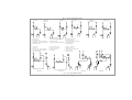
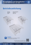
BETRIEBSANLEITUNG
Stations- und Batteriedruckminderer
Typ 16, 22, 24, 25, 27, 30 und 32
Gas Panels
Type 16, 22, 24, 25, 27, 30 and 32
OPERATING INSTRUCTIONS
Diese Armaturen sind Präzisionsinstrumente von höchster Qualität. Durch die Verwendung ausgewählter Materialien, durch
hohe Oberflächengüte und Dichtheit lassen sich Druck und
Durchfluß auch von reinsten Gasen ohne Beeinträchtigung der
Reinheit präzise mit gleichbleibender Genauigkeit regeln. Alle
Schritte - von der Konzeption, über die Fertigung bis zur Endkontrolle - unterliegen den strengen Kriterien unserer Qualitätssicherung nach DIN EN ISO 9001.
2. GRUNDLEGENDE SICHERHEITSHINWEISE
2.1 Hinweise in der Bedienungsanleitung
Diese Bedienungsanleitung enthält die wichtigsten Hinweise,
um das Druckgerät sicherheitsgerecht zu betreiben. Die
Sicherheitshinweise sind von allen Personen zu beachten, die
an den Armaturen arbeiten. Darüberhinaus sind die für den Einsatzort geltenden Regeln und Vorschriften zur Unfallverhütung
zu beachten.
2.2 Verpflichtung des Betreibers
Der Betreiber verpflichtet sich, nur Personen am Druckgerät arbeiten zu lassen, die
mit den grundlegenden Vorschriften über Arbeitssicherheit und Unfallverhütung vertraut sind und andauernd
Zugang zu diesen Vorschriften haben,
das Sicherheitskapitel und die Warnhinweise in dieser
Bedienungsanleitung gelesen und verstanden haben und
geschult und an der Reduzierstation eingewiesen sind.
Das sicherheitsbewußte Arbeiten des Personals wird in
regelmäßigen Abständen überprüft.
Die Zuständigkeiten des Personals für das Montieren,
Inbetriebnahme und Bedienen sind klar festzulegen.
Anzulernendes Personal darf nur unter Aufsicht einer
erfahrenen Person am Druckgerät arbeiten.
Alle Sicherheits- und Gefahrenhinweise sind stets in
lesbarem Zustand zu halten.
2.3 Verpflichtung des Personals
Alle Personen, die mit Arbeiten am Druckgerät beauftragt sind, verpflichten sich vor Arbeitsbeginn
die grundlegenden Vorschriften über Arbeitssicherheit
und Unfallverhütung zu beachten,
sich mit dem Sicherheitsdatenblatt der verwendeten
Gasart vertraut zu machen.
Verwendung anderer Gasarten, der Überschreitung der
zulässigen Eingangsdrücke, der Verwendung fremder
bzw. nicht originaler Dichtungen.
Mangelhafte Überwachung von Ausrüstungs-, Verschraubungs- und Dichtungsteilen, die einem Verschleiß
unterliegen.
Unsachgemäß durchgeführte Reparaturen.
Überschreitung oder Unterschreitung des im Datenblatt
angegebenen Temperaturbereichs während des Betriebs
bzw. während der Lagerung.
Katastrophenfälle durch Fremdkörpereinwirkung und höhere Gewalt.
2.4 Gefahren im Umgang mit dem Druckgerät
Der Batterie-, bzw. Stationsdruckminderer (Druckgerät) ist
nach dem Stand der Technik und den anerkannten sicherheitstechnischen Regeln gebaut. Dennoch können bei ihrer
Verwendung Gefahren für Leib und Leben des Benutzers
oder Dritter bzw. Beeinträchtigungen am Druckgerät oder an
anderen Sachwerten entstehen.
Das Druckgerät ist nur für die bestimmungsgemäße
Verwendung zu benutzen .
Störungen, die die Sicherheit beeinträchtigen können,
sind umgehend zu beseitigen.
2.5 Bestimmungsgemäße Verwendung
Das Druckgerät ist ausschließlich zur Entspannung von gasförmigen Medien aus Druckgasbehältern bestimmt.
Eine andere oder darüber hinausgehende Benutzung gilt als
nicht bestimmungsgemäß.
Zur bestimmungsgemäßen Verwendung gehört auch
das Beachten aller Hinweise aus der Bedienungsanleitung,
die Einhaltung der Inspektions- und Wartungsarbeiten,
das Beachten des Typenschildes und des Datenblattes.
2.7 Symbol- und Hinweiserklärung
In der Bedienungsanleitung werden folgende Benennungen
und Zeichen für Gefährdungen verwendet:
Dieses Symbol bedeutet eine unmittelbar drohende Gefahr für das Leben und die Gesundheit
von Personen. Das Nichtbeachten dieser Hinweise
hat schwere gesundheitsschädliche Auswirkungen
zur Folge, bis hin zu lebensgefährlichen Verletzungen.
Dieses Symbol bedeutet eine möglicherweise
drohende Gefahr für das Leben und die Gesundheit von Personen. Das Nichtbeachten dieser Hinweise kann schwere gesundheitsschädliche Auswirkungen zur Folge haben, bis hin zu lebensgefährlichen Verletzungen.
2.6 Gewährleistung und Haftung
Grundsätzlich gelten unsere "Allgemeinen Verkaufs- und
Lieferbedingungen". Diese stehen dem Betreiber spätestens
seit Vertragsabschluß zur Verfügung. Gewährleistungs- und
Haftungsansprüche bei Personen- und Sachschäden sind
ausgeschlossen, wenn sie auf eine oder mehrere der folgenden Ursachen zurückzuführen sind:
Nicht bestimmungsgemäße Verwendung des Druckgerätes.
Unsachgemäßes Montieren, Inbetriebnahme, Bedienen
und Warten des Druckgerätes.
Betreiben des Druckgerätes bei defekten Sicherheitseinrichtungen oder nicht ordnungsgemäß angebrachten
oder nicht funktionsfähigen Sicherheits- und Schutzvorrichtungen.
Nichtbeachten der Hinweise in der Bedienungsanleitung
bezüglich Transport, Lagerung, Montage, Inbetriebnahme,
Betrieb, Wartung und Rüsten des Druckgerätes.
Eigenmächtige bauliche Veränderungen an dem Druckgerät.
Eigenmächtiges Verändern der Flaschenanschlüsse zur
-1-
+
Dieses Symbol bedeutet eine möglicherweise
gefährliche Situation. Das Nichtbeachten dieser
Hinweise kann leichte Verletzungen zur Folge haben
oder zu Sachbeschädigungen führen.
Dieses Symbol gibt wichtige Hinweise für den
sachgerechten Umgang mit dem Druckgerät und Sie
erhalten Anwendungs-Tips und besonders nützliche
Informationen. Das Nichtbeachten dieser Hinweise
kann zu Störungen am Druckgerät oder in der Umgebung führen. Anwendungstips helfen Ihnen, alle
Bedienungsanleitung SMD, BMD
1. ALLGEMEINES
1.1 Vorbemerkung
Bedienungsanleitung SMD, BMD
Funktionen an Ihrem Druckgerät optimal zu nutzen.
2.8 Organisatorische Maßnahmen
Die erforderlichen persönlichen Schutzausrüstungen
sind vom Betreiber bereitzustellen.
Alle vorhandenen Sicherheits-Einrichtungen sind regelmäßig zu überprüfen.
Bei Sauerstoffmangel oder zu hoher Schadstoffkonzentration sind von der Umgebungsatmosphäre unabhängige Atemschutzgeräte erforderlich (VBG 1).
2.9 Schutzeinrichtungen
Vor jeder Inbetriebnahme des Druckgerätes müssen alle
Sicherheitseinrichtungen sachgerecht angebracht und
funktionsfähig sein.
Schutzvorrichtungen und Sicherheitseinrichtungen dürfen nur nach Außerbetriebsetzen des Druckgerätes bzw.
der Anlage und Absicherung gegen Wiederinbetriebnahme des Druckgerätes entfernt werden.
Bei Lieferung von Teilkomponenten sind die Sicherheitseinrichtungen durch den Betreiber vorschriftsmäßig anzubringen.
2.10 Anlagen-Steuerung
Auf keinen Fall Programmänderungen vornehmen!
Nur eingewiesenem Personal ist es erlaubt, die Steuerung zu betätigen.
2.11 Sicherheits-Maßnahmen im
Normalbetrieb
Vor Einschalten des Druckgerätes sicherstellen, daß
niemand durch das Inbetriebnehmen des Druckgerätes
gefährdet werden kann.
Mindestens einmal pro Jahr das Druckgerät auf Dichtheit und Funktionsfähigkeit der Sicherheitseinrichtungen überprüfen.
2.12 Gefahren durch elektrische Energie
Arbeiten an elektrischen Bauteilen, Anzeige- und Steuerungseinheiten (z.B. Gasmangelanzeige) nur von einer
Elektro-Fachkraft ausführen lassen.
Die elektrische Ausrüstung der Anlage regelmäßig überprüfen. Lose Verbindungen und beschädigte Kabel
sofort beseitigen.
Der Schaltschrank bzw. die elektrischen Baugruppen
sind stets verschlossen zu halten. Der Zugang ist nur
autorisiertem Personal mit Schlüssel oder Werkzeug erlaubt.
Sind Arbeiten an spannungsführenden Teilen notwendig,
ist eine zweite Person hinzuzuziehen, die notfalls den
Hauptschalter ausschaltet.
2.13 Gefahren durch Druckenergie
Zu öffnende Systemabschnitte und Druckleitungen vor
Beginn von Reparaturarbeiten drucklos machen.
Flexible Schlauchleitungen in angemessenen Zeitabständen überprüfen und auswechseln, auch wenn keine
sicherheitsrelevanten Mängel erkennbar sind.
Durch äußere Einwirkungen wie hohe Temperaturen,
Wärmestrahlung, Stoß und ähnliches können sich
Druckgasflaschen oder unter Druck stehende Anlagenteile stark erwärmen bzw. bersten. Treffen Sie bitte
entsprechende Vorsichts- und Sicherheitsmaßnahmen.
2.14 Besondere Gefahren durch
Leckage nach außen
Durch die Verwendung von sehr gefährlichen, gefährlichen
oder weniger gefährlichen Gasen können bei Undichtigkeit
des Druckgerätes Gefahren für Leib und Leben des Benutzers entstehen.
Deshalb ist eine Betriebsanweisung gemäß § 20 GefStoffV, ein aktuelles EU-Sicherheitsdatenblatt nach §
14 GefStoffV und ein Unfallmerkblatt mit Hinweisen für
den Arzt an geeigneter Stelle vorzuhalten.
Die Bediener sind auf die besonderen Gefahren des Gases und auf eventuelle Personen- und andere Schutzmaßnahmen hinzuweisen.
2.15 Hinweise zu speziellen Gasarten
Alle mit Sauerstoff in Berührung kommenden Teile müssen absolut öl- und fettfrei sein, Brand- und Explosionsgefahr!
Nur Schmierstoffe mit Sauerstoffzulassung verwenden.
Bei Acetylen keine Rohrleitungen oder andere Anlagenteile aus Kupfer verwenden! Besondere Gefährdungspotentiale des Acetylens beachten!
2.16 Austreten schädlicher Gase und
Dämpfe
Bei geöffneten Sicherheitseinrichtungen oder Störfällen
können schädliche Gase und Dämpfe entweichen (s. o.).
Für ausreichend Entlüftung oder Absaugung sorgen.
-2-
Bei gefährlichen Medien besondere Schutzvorkehrungen
treffen. Insbesondere Abblaseventil und Spülventile
über feste Rohrleitungen ableiten und die Stoffe sicherheitsgerecht und umweltverträglich entsorgen.
2.17 Wartung und Instandhaltung,
Störungsbeseitigung
Vorgeschriebene Einstell-, Wartungs- und Inspektionsarbeiten fristgemäß durch den Hersteller oder durch
vom Hersteller autorisierten Fachbetrieben durchführen
lassen.
Bedienungspersonal und Nutzer vor Beginn der Wartungs- und Instandhaltungsarbeiten informieren.
Alle zur Ansteuerung der Druckgeräte bzw. der Anlage
vor- und nachgeschalteten Betriebsmedien wie Druckluft und Hydraulik gegen unbeabsichtigte Inbetriebnahme absichern.
Bei allen Wartungs-, Inspektions- und Reparaturarbeiten die zugehörigen Betriebsmittel spannungsfrei schalten und Hauptschalter gegen unerwartetes Wiedereinschalten sichern.
Hauptschalter abschließen und Schlüssel abziehen.
Ein Warnschild gegen Wiedereinschalten anbringen.
Gelöste Schraubverbindungen auf festen Sitz kontrollieren.
Nach Beendigung der Wartungsarbeiten Sicherheitseinrichtungen auf Funktion überprüfen.
2.18 Bauliche Veränderungen an dem
Druckgerät oder der Anlage
Ohne schriftliche Genehmigung des Herstellers keine
Veränderungen, An- oder Umbauten am Druckgerät oder
der Anlage vornehmen.
Anlagenteile in nicht einwandfreiem Zustand sofort austauschen.
Nur Original-Ersatz- und Verschleißteile verwenden.
2.19 Reinigen der Gasgeräte und
Entsorgung der Rückstände
Verwendete, zur Reparatur anstehende Gasgeräte mit
einem inerten Gas (Stickstoff, Argon) spülen. Feste
Gasrückstände sachgerecht handhaben und entsorgen.
Insbesondere nicht durch ölige Lappen oder mit
Schmierstoffen verunreinigen. Nicht mit Lösungsmitteln
Gesetze und Verordnungen
GSG Gerätesicherheitsgesetz
mit aVV allgem. Verwaltungsvorschrift zum GSG, 6.
GSGV Druckbehälterverordnung, 7. GSGV Gasverbrauchseinrichtungsverordnung und GasHL-VO Gashochdruckleitungsverordnung.
ChemG Chemikaliengesetz
mit GefStoffV Gefahrstoffverordnung und ArbstoffV Arbeitsstoffverordnung.
AcetV Acetylenverordnung.
BImSchG Immissionsschutzgesetz
mit BImSchV FCKW-Halon-Verbots-Verordnung und 2.
BImSchV Emissionsbegrenzung von leichtflüchtigen Halogenkohlenwasserstoffen.
Techn. Regeln, Unfallverhütungsvorschriften.
TRAC Techn. Regeln für Acetylenanlagen und Calciumcarbidlager
TRAC 204, 206, 207, 208.
Technische Regeln
TRB 610, 700, 801 / 26, 801 / 27.
TRR Techn. Regeln Rohrleitungen
TRR 100.
TRG Techn. Regeln Druckgase
TRG 100, 101, 102, 103, 104, 250, 253, 254, 256, 280,
310, 311, 360, 370.
TRGL Technische Regeln für Gashochdruckleitungen
TRGL 101, 111, 141, 151, 161, 171, 181, 191, 195, 201,
211, 231, 241, 242, 251, 261, 291, 295, 501, 511, 521.
UVV Unfallverhütungsvorschriften
VBG 1, 4, 15, 50, 61, 62.
ZH 1 Schriften, Merkblätter, Sicherheitsregeln
ZH1/8 u.f., ZH1/10, ZH1/15, ZH1/16, ZH1/20, ZH1/20.1,
CEN-Normen (European Committee for Standardization)
EN 585, 562.
4.4 Kennzeichnung
Die Typenschilder weisen folgende Kennzeichnungen aus:
DIN-Normen (Deutsches Institut für Normung e.V.)
DIN 8545, 3380, 2462, 2403, 12920, 12925, 16006.
VDE-Richtlinien (Verband Deutscher Elektrotechniker)
VDE 0100, 0170, 0190.
Datenblätter
Baureihe 100, 200, 230, 330 und 500.
3. LAGERUNG, TRANSPORT
Alle Teile müssen sauber verpackt, staubfrei, trocken und
gut verschlossen gelagert werden. Nur sachgerechte Verpackung benützen. Keine lösungsmittelhaltigen Reinigungsmittel anwenden!
Vor Rücksendung an den Hersteller unbedingt alle Komponenten, die mit korrosiven
oder toxischen Gasen in Kontakt waren, mit
Inertgas spülen.
4. TECHNISCHE DATEN
4.1 Druckminderer
Maximal sechs Ein- und Ausgangsbohrungen mit NPT 1/4”Innengewinde ermöglichen vielfältige Anschluß- und Variationsmöglichkeiten des Druckminderers.
4.2 Absperrventil MVA
Durch 90°-Drehung einfach zu bedienendes Absperrventil
mit Einrasteffekt (Klick). Die Auf-/Zu-Stellung ist eindeutig
erkennbar: Handrad parallel zur Gasleitung - Ventil geöffnet.
Handrad quer zur Gasleitung - Ventil geschlossen.
4.3 Zubehör
Für die Baureihen ist umfangreiches Zubehör wie Verschraubungen, Schlauchtüllen, Kontaktmanometer und
-3-
Typ:
Wst:
SMD 500-14
Ms/PVDF/EPDM
pein :
200 bar
paus : 1 - 12 bar
Achtung!
Druckbelastete Teile.
Service nur durch
autorisierte Personen
He
Hersteller, Herstellungszeitpunkt, Typbezeichnung, Zugelassener Vordruck (p ein), gerätespezifischer Hinterdruckbereich (paus ), Werkstoffe von Druckminderergehäuse und
Sitzdichtung, Sicherheitshinweis und Kurzzeichen für die
Gasart. Die Seriennummer wird als gerätespezifische Kennzeichnung auf einem separaten Schild im Barcode 128 und in
Klarschrift angegeben.
4.5 Fließschemata
Abbildung 1 zeigt die Fließschemata von Stations- und
Batteriedruckminderern des Standardlieferprogramms.
5. AUFSTELLUNG, MONTAGE, ERSTE
INBETRIEBNAHME
5.1 Befestigung der Armaturen
+
Die Entspannungsstation ist stabil an der
Wand zu befestigen. Die Montagehöhe der
unteren Befestigungsleiste (Bohrung Konsole) beträgt 164 cm.
Zur sicheren Handhabung sind für die Arretierung der Gasflaschen Halterungen (lieferbares Zubehör) anzubringen.
5.2 Vorbereitungen
Kontrollieren Sie zuerst an Hand des Typenschildes und der Beschriftung, ob der Druckminderer für den vorgesehenen Verwendungszweck geeignet ist (Gasart, Druck,
Werkstoff).
Bedienungsanleitung SMD, BMD
2.21 Gesetze, Verordnungen, Normen,
Vorschriften.
ISO Normen (Internat. Organisation for Standardization)
ISO 2503.
Flammensperren lieferbar. Bitte wenden Sie sich diesbezüglich an den Hersteller.
Montage- und Einbauvorschriften für diese Komponenten
sind unbedingt zu befolgen.
95.10.
In einigen Fällen kann das ungünstige Zusammenwirken bestimmter Einflußgrößen wie z. B. Durchfluß und Druckbereich aber auch die Gasart selbst zu Geräuschentwicklungen führen. Bitte setzen Sie sich in solchen Fällen mit dem Hersteller in Verbindung.
ZH1/108 u.f., ZH1/119, ZH1/180, ZH1/244, ZH1/288, ZH1/
298, ZH1/307, ZH1/309, ZH1/383, ZH1/384, ZH1/399,
ZH1/400, ZH1/409, ZH1/479, ZH1/605.
Hersteller
reinigen.
2.20 Geräuschentwicklung
Bedienungsanleitung SMD, BMD
Überprüfen Sie, ob der Werkstoff der weiterführenden Versorgungsleitung für die entsprechende Gasart geeignet ist.
Schließen Sie dann die Versorgungsleitung an den Brauchgasausgang des Stations- bzw. Batteriedruckminderers an.
Als Anschlußverschraubung empfehlen wir Klemmringverschraubungen, die - falls mitbestellt - bereits in den
Ausgang der Armatur eingedichtet sind. Die Montage erfolgt
durch Einführen des Rohres in die Öffnung der Überwurfmutter der Verschraubung bis zum Anschlag. Die Überwurfmutter wird zunächst mit der Hand dann mit einem Gabelschlüssel (1 ¼ Umdrehungen) fest angezogen.
Abblaseventil und Spülausgang werden, soweit vorhanden,
in gleicher Weise an eine Abgasleitung angeschlossen. Bitte
die Abgasleitung an eine geeignete und gefahrlose Stelle
führen und ausreichende Länge vorsehen (Personengefährdung!).
5.2.1 Montage der Anschlußwendel an die
Station
Die Edelstahl-Wendelleitung zur Verbindung der Station mit
der Gasflasche wird immer separat mitgeliefert. Zunächst
die richtige Zuordnung der Wendelleitung zur Armatur überprüfen. Auf der Anschlußmutter der Wendelleitung ist die
Nummer eingeschlagen, welche der Gasartzuordnung gemäß
DIN 477 entspricht. Es gibt nur eine Ausführung von Anschlußwendeln. Diese ist für den Anschluß an Stations- als
auch Batteriedruckminderer (linke und rechte Seite) gleichermaßen geeignet.
Zur Montage der Anschlußwendel an die Station zunächst
die Kunststoffschutzkappe vom Anschlußgewinde der Station und aus der Wendel-Anschlußmutter entfernen. Bitte
darauf achten, daß die mitgelieferte Flachdichtung in die
Überwurfmutter eingelegt ist. Die Überwurfmutter dann auf
das Anschlußgewinde am Eingang der Station zunächst von
Hand aufschrauben und anschließend mit einem Gabelschlüssel (SW 17) festziehen.
5.2.2 Anschließen der Anschlußwendel an
die Gasflasche
Gewinde von Flaschenventil und Überwurfmutter an Wendel müssen in einwandfreiem
Zustand sein.
Immer nur neue Dichtungen verwenden. Dichtungen
dürfen nicht deformiert sein und keine Spuren von
Schmutz oder Metallspänen aufweisen.
Nur Original-Flaschenanschlußwendeln des Herstellers entsprechend der eingesetzten Gasart verwenden.
Dichtungen auf richtigen Sitz im Anschlußstutzen
der Wendel überprüfen.
Auf Links- oder Rechtsgewinde der Flaschenanschlußmutter achten. Linksgewinde sind dadurch gekennzeichnet,
daß auf der Außenseite der Mutter eine umlaufende Nut
eingefräst ist. Die Mutter zunächst von Hand auf das
Flaschenventilgewinde aufschrauben, dann mit einem Gabelschlüssel fest anziehen. Dabei am Haltegriff der Wendelleitung unbedingt gegenhalten.
Keine Schlüsselverlängerungen benützen, da
sonst Gewinde und Dichtung zerstört werden
können. Dies kann zu Leckage und unkontrolliertem Gasaustritt führen!
5.3 Eigengasspülung
+
Stations- oder Batteriedruckminderer mit
Eigengasspülung werden eingesetzt, damit
die beim Flaschenwechsel ins System eingedrungene Atmosphärenluft entfernt werden kann.
1. Spülgasausgangsventil (9) und Brauchgasausgangsventil
(6) - soweit vorhanden - schließen (Ventilgriff steht quer
zur Rohrleitung).
2. Handbetätigtes Brauchgaseingangsventil (11) schließen.
Bei Geräten ohne oder mit automatisierten Eingangsventilen
muß der Druckminderer (3) durch Drehen des Handrades
gegen den Uhrzeigersinn entlastet (geschlossen) werden.
3. Flaschenventil (1) langsam öffnen.
4. Brauchgas in die Wendelleitung (2) strömen lassen und
dort einige Sekunden verweilen lassen. Flaschenventil (1)
wieder schließen.
5. Spülausgangsventil (9) kurz öffnen und die jetzt in der
Wendelleitung enthaltene Gasmenge entweichen lassen.
Spülausgangsventil (9) dann sofort wieder schließen.
6. Die Schritte 3. bis 5. fünf- bis siebenmal wiederholen.
5.4 Fremdgasspülung
+
Stationen mit Fremdgasspülung ermöglichen:
-4-
+
die Trocknung der Armatur bzw. das Entfernen feuchter Atmosphärenluft, die vor der
Inbetriebnahme oder beim Flaschenwechsel
in die Station eingedrungen sein kann,
das Freispülen der Armatur von giftigen, korrosiven oder selbstentzündlichen Gasen vor
dem Flaschenwechsel und vor Außerbetriebnahme.
Trockenes, sauberes Spülgas N 2 5.0 oder Ar
5.0 ist Voraussetzung für ein erfolgreiches
Spülen.
1. Überprüfen, ob Spülgaseingang (12), Spülgasausgang (10),
Brauchgasausgang (7) und Anschlußwendel (2) ordnungsgemäß angeschlossen sind.
2. Brauchgasausgangsventil (6), Brauchgaseingangsventil
(11) sowie Spülgaseingangsventil (14) und Spülgasausgangsventil (9) schließen (Handrad der Ventile steht quer zur
Rohrleitung).
3. Druckminderer (3) durch Drehen des Handrades gegen den
Uhrzeigersinn schließen (entlasten).
4. Spülgaseingangsventil (14) öffnen.
5. Brauchgaseingangsventil (11) l a n g s a m öffnen.
6. Druckminderer (3) durch Drehen des Handrades um ca. zwei
Umdrehungen im Uhrzeigersinn teilweise öffnen.
7. Das Spülgaseingangsventil (14) schließen. Das jetzt in die
Station eingeströmte Spülgas einige Sekunden verweilen
lassen.
8. Das Spülgasausgangsventil (9) kurz öffnen und Spülgas
über den Spülgasausgang (10) entweichen lassen. Das Spülgasausgangsventil (9) sofort wieder schließen.
9. Die Schritte 4., 7. und 8. fünf- bis siebenmal wiederholen.
10. Alle Ventile der Station schließen. Druckminderer (3)
durch Drehen des Handrades gegen den Uhrzeigersinn vollständig schließen.
5.5 Inbetriebnahme
Bei Verwendung von giftigen, korrosiven oder
selbstentzündlichen Gasen ausschließlich
Stationen mit Fremdgasspülung vorsehen.
Vor Inbetriebnahme muß an Hand des Typenschildes überprüft werden, ob die vorliegende Armatur für den vorgesehenen Verwen-
6. FLASCHENWECHSEL UND
AUSSERBETRIEBNAHME
6.1 Flaschenwechsel
+
Beim Wechseln der Flaschen mit giftigen, korrosiven Gasen sind entsprechende
Personenschutzmaßnahmen zu treffen (Atemschutz, Augenschutz und Schutzkleidung).
MAK-Werte (siehe Technische Regeln für
Gefahrenstoffe, TRGS 900) beachten, richtige
Atemschutzfilter bereit halten.
Wurden aus der Druckgasflasche giftige
oder korrosive Gase entnommen, ist vor dem
Auswechseln der leeren Flasche die Anlage
mit inertem Gas zu spülen (s. Kap. 5.4 ”Fremdgasspülung). Damit wird erreicht, daß sich
das in der Leitung befindliche Restgas
durch die Abgasleitung sicher entsorgt wird.
1. Flaschenventil (1) an der Gasflasche schließen.
2. Brauchgasausgangsventil (6) und/oder -eingangsventil
(11) - soweit vorhanden - schließen.
3. Bei giftigen, korrosiven oder selbstentzündlichen Gasen
die Fremdgasspülung durchführen (s. Kap. 5.4).
4. Anschlußwendel (2) vom Flaschenventil (1) lösen.
5. Bei Verwendung eines Trockenfilters den Filterkorb bei
jedem Flaschenwechsel austauschen (siehe separate Anleitung).
6. Neue Brauchgasflasche anschließen. (s. Kap. 5.2.2).
7. Vor Wiederinbetriebnahme der Armatur ggf. Eigengasspülung (s. Kap. 5.3) bzw. Fremdgasspülung (s. Kap. 5.4) mit
nachfolgender Eigengasspülung (s. Kap. 5.3) durchführen.
6.2 Außerbetriebnahme
Bei kurzzeitiger Unterbrechung der Gasentnahme genügt das
Schließen des Brauchgasausgangsventils (6). Das Schließen
des Druckminderers (3) alleine garantiert keine Dichtheit, es
kann ein Gasaustritt durch die Schläuche oder die angeschlossenen Verbraucher stattfinden. Bei längerer Unterbrechung muß der Druckminderer (3) durch Drehung des
Handrades gegen den Uhrzeigersinn entspannt werden.
Aus Sicherheitsgründen immer das Flaschenventil schließen.
Bei Ausbau der kompletten Ein- oder Zweiflaschenanlage
generell beachten:
+
Druckregler und Leitungen durch Ableiten
des Gases über den Verbraucher entspannen,
Zeiger von Vor- und Hinterdruckmanometer
müssen vollständig auf ”O” stehen.
Entsprechende Personenschutzmaßnahmen
sind zu treffen (Atemschutz, Augenschutz
und Schutzkleidung).
MAK-Werte (siehe Technische Regeln für
Gefahrenstoffe, TRGS 900) beachten, richtige
Atemschutzfilter bereit halten.
Bei korrosiven bzw. giftigen Gasen alle Komponenten mit Inertgas spülen (siehe Kap. 5.4
"Fremdgasspülung").
-5-
7. WARTUNG UND BETRIEBS- STÖRUNGEN
7.1 Wartung
Reparaturen und Wartungen sind aus Sicherheitsgründen nur vom Hersteller oder durch
vom Hersteller autorisierte Fachbetriebe
ausschließlich mit Originalersatzteilen
durchzuführen.
Bei Stationen mit Trockenfilter beachten
Sie bitte die spezielle Bedienungsanleitung.
Flexible Schlauchleitungen sind einmal
jährlich durch einen Drucktest auf Dichtheit
zu prüfen und gegebenenfalls auszuwechseln.
Um eine einwandfreie Funktion und gleichbleibende Betriebssicherheit der Armaturen sicherzustellen, sollen alle
Komponenten einer Gasversorgung jährlich einmal vom Hersteller überprüft werden. Hierfür empfiehlt sich der
Abschluß eines Wartungsvertrages.
Bitte beachten Sie die Garantie- und Lieferbedingungen des
Herstellers sowie die Grundlegenden Sicherheitshinweise
im zweiten Kapitel.
7.2 Betriebsstörungen
Diese Druckminderer arbeiten stets sehr zuverlässig. Sollte
dennoch der Hinterdruck unzulässig ansteigen und/oder das
Abblaseventil ansprechen, so setzen Sie sich bitte mit dem
Hersteller in Verbindung.
8. HERSTELLUNG
Technische Änderungen, die dem Fortschritt dienen, sind
vorbehalten.
Printed in Germany. Ausgabe
BA BSMD Typ -16-22-24-25-27-30-32 d&e.pmd.
V1/230305. © Hersteller siehe Aufdruck Rückseite.
Bedienungsanleitung SMD, BMD
dungszweck geeignet ist (Gasart, Druck,
Werkstoff, etc.)
Vor Einschalten des Druckgerätes sicherstellen, daß niemand durch das Inbetriebnehmen des Druckgerätes gefährdet
werden kann.
Vor Inbetriebnahme und Befüllen des nachfolgenden Leitungssystems gegebenenfalls Eigengasspülung (s. Kap. 5.3) bzw.
Fremdgasspülung (s. Kap. 5.4) mit nachfolgender Eigengasspülung (s. Kap. 5.3) durchführen und alle Verschlußstopfen
entfernen. Aus Sicherheitsgründen empfehlen wir in jedem Fall
die Montage einer Abgasleitung.
1. Überprüfen, ob Spül-, Abgasleitungen und die Wendel ordnungsgemäß angeschlossen sind.
2. Alle Ventile der Armatur schließen (Griff quer zur Rohrleitung).
3. Handrad des Druckminderers (3) bis zum Anschlag gegen
den Uhrzeigersinn drehen - Durchgang ist damit geschlossen.
4. Flaschenventil (1) langsam öffnen.
5. Brauchgaseingangsventil (11) (soweit vorhanden)
langsam !! öffnen.
6. Gewünschten Hinterdruck durch Drehen des Handrades
im Uhrzeigersinn am Druckminderer (3) einstellen.
7. Brauchgasausgangsventil (6), soweit vorhanden, (insbesondere bei großen nachgeschalteten Rohrvolumen) l a n g
s a m !! öffnen.
Abb.1: Fließschemata BMD und SMD
SMD ##2-16
SMD ##0-16
SMD ##0-16
7
SMD ##0-22
7
SMD ##2-22
SMD ##0-24
7
10
7
10
7
5
6
3
5 4
2
1
8
5
6
7
8
1 cylinder valve
2 spiral tube
3 press.reg. single stage: Typ ##0-xx
press.reg. double stage: Typ ##2-xx
4 inlet pressure gauge
10
outlet pressure gauge
process gas outlet valve
process gas outlet
safety valve
9
10
11
12
13
Spülgasausgangsventil
Spülgasausgang
Brauchgaseingangsabsperrventil
Spülgaseingang
Rückschlagventil
9
10
11
12
13
purge gas outlet valve
purge gas outlet
process gas inlet shut-off valve
purge gas inlet
non return valve
7
5
3
13
6
5 4
8
7
8
4
11
5
4
9
9
3
14
11
11
11
2
2
1
1
2
1
1
2
8
SMD ##2-27
BMD ##0-30
fig. 1: flow scheme BMD and SMD
-6-
2
1
1
8
SMD ##0-27
2
1
11
3
11
3
3
9
11
2
9
8
13
14
4
2
10
12
10
5
6
11
1
12
7
9
9
8
Hinterdruckmanometer
Brauchgasausgangsabsperrventil
Brauchgasausgang
Sicherheitseinrichtung: Abblaseventil
5
6
7
8
4
3
2
8
1 Flaschenventil
2 Anschlußwendel
3 Druckminderer einstufig: Typ ##0-xx
Druckminderer zweistufig: Typ ##2-xx
4 Vordruckmanometer
5 4
5
3
1
1
8
9
9
3
2
8
7
6
3
2
1
4
4
5
6
5 4
6
6
SMD ##0-25
7 SMD ##0-24 10
10
BMD ##0-32
1. General
2. Fundamental safety instructions
3. Storage and transport
4. Technical data
5. Installation, assembly, commissioning
6. Changing cylinders and ending operation
7. Servicing and malfunctions
8. This document
1.2 PREFACE
These pure gas components are precision instruments of
superior quality. The individual components are
coordinated with each other and allow the flexible
configuration of high-quality pure gas supply systems.
The use of selected materials, high-quality surface finishing and excellent leak tightness ensure that the
pressure and flow of even the purest gases can be
controlled with constant precision without contamination
of purity. All of the steps involved - from design to manufacture to final quality inspection - must meet the strict
criteria of our quality assurance program.
2. FUNDAMENTAL SAFETY INSTRUCTIONS
2.1 Information in the
operating instructions
The essential information which is required for safe operation
of the pressure device is contained in these operating
instructions. The safety instructions must be observed by all
persons who work on the fittings. Additionally, the rules and
regulations which apply at the operating location must be
observed.
2.2 Obligation on operating authority
The operating authority undertakes to allow only such
persons to work on the pressure device who
are familiar with the fundamental regulations concerning
occupational safety and accident prevention, and who always have access to these regulations,
have read and understood the chapter on safety and the
warnings in these operating instructions and
have been trained, and introduced to the reduc-ing station.
Safety-conscious working of personnel is to be checked
at regular intervals.
Responsibility of personnel for assembly, start-up and
operation must be clearly defined.
Trainees must only work on the pressure device under
supervision by an experienced person.
All information on safety and danger must always be kept
in a legible condition.
2.3 Obligation on personnel
Before starting work, all persons who are instructed to
work on the pressure device undertake to
observe the fundamental regulations concerning occupational safety and accident prevention,
familiarize themselves with the safety data sheet for
the type of gas being used.
2.4 Dangers associated with handling of the
pressure device
The battery or station pressure regulator (pressure device)
is constructed according to state-of-the-art and recognized
safety rules. Despite this, use of the device can cause
danger to life and limb of the user or third parties, or
damage to the pressure device or other property.
The pressure device must only be used for the intended
use.
Malfunctions which could impair safety must be rectified immediately.
2.5 Intended use
The pressure device is only to be used for expanding
gaseous media from gas cylinders.
Any use other than or exceeding this is regarded
as improper use.
The intended use also encompasses
observing all information in the operating instructions,
carrying out inspection and maintenance work,
observing the rating plate and the data sheet.
2.6 Guarantee and liability
Our “General Conditions of Sale and Delivery” apply. These
are available to the operating authority at the latest on
formation of the contract. Guarantee and liability claims
-7-
regarding personal injury and damage to property are
excluded if they result from one or more of the following
causes:
Improper use of the pressure device.
Incorrect assembly, start-up, operation or
servicing of the pressure device.
Operation of the pressure device with defective safety
equipment, or with incorrectly installed or non-functioning safety and protection devices.
Non-observance of information in the operating instructions relating to transport, storage, assembly, start-up,
operation, servicing and equipping of the pressure device.
Unauthorized constructional alterations to the pressure
device.
Unauthorized alteration of the cylinder connections for
use of other gas types, exceeding of permissible inlet
pressures, use of extraneous or non-original seals.
Insufficient monitoring of equipment, screwed fittings,
and sealing parts, which are subject to wear.
Repairs carried out incorrectly.
Temperature exceeds or falls below the temperature
range indicated in the data sheet, during operation or
storage.
Unforseen calamities resulting from effect of foreign
body or force majeure.
2.7 Explanation of symbols and information
The following designations and symbols are used in the
operating instructions to indicate dangers:
This symbol indicates an immediate threat of
danger to the life and health of persons. Ignoring
this information will have serious consequences
which are damaging to health. This may include lifethreatening injury.
This symbol indicates a possible threat of danger to the life and health of persons. Ignoring this
information can have serious consequences which
are damaging to health. This may include life-threatening injury.
Operating instructions SMD, BMD
1. GENERAL
1.1 Contents
Operating instructions SMD, BMD
This symbol indicates a situation which might
be dangerous. Ignoring this information can result in minor injury or damage to property.
+
This symbol indicates important information for
correct handling of the pressure device. Hints for
operation and particularly useful information are
provided. Ignoring this information can result in
malfunctions at the pressure device or in the surrounding area. Hints for operation help you to use
all the functions of your pressure device optimally.
2.8 Organizational measures
The required personal protective equipment must be
provided by the operating authority.
All the safety devices must be checked regularly.
In case of oxygen shortage or excessive contaminant
concentration, respiratory equipment which is independent of the surrounding atmosphere is required (VBG 1).
2.9 Protective equipment
Every time the pressure device is started up, all safety
equipment must first be correctly fitted and in working
order.
Protective devices and safety equipment must only be
removed after the pressure device or system has been
put out of operation and the pressure device has been
secured against re-starting.
When partial components are supplied the operating authority must ensure that the safety equipment is fitted
correctly.
2.10 System controller
Never make alterations to the programme!
The controller must be operated by trained personnel
only.
2.11 Safety measures in normal operation
Before switching on the pressure device, ensure that noone can be put in a situation of danger due to the pressure device start-up.
Check the pressure device for leaks and correct func-
tion of safety equipment at least once annually.
2.12 Danger from electricity
Have work on electrical components, display units and
control units carried out only by a trained electrician.
Check the electrical equipment of the system regularly.
Rectify loose connections and damaged cable immediately.
The switch cabinet and the electrical units must be kept
closed. Access is restricted to
authorized personnel with key or tools.
If work must be carried out on live components, a second person must be present to switch off the main
switch if necessary.
2.13 Danger from pressure
Sections of the system and pressure lines which are to
be opened must be depressurized before starting repair
work.
Check flexible hose lines at appropriate intervals. Replace them even if defects relevant to safety are not
found.
External inflences such as high temperatures, heat radiation, impact and similar can cause gas cylinders or
pressurized parts of the system to heat up excessively
or burst. Please take the appropriate precautionary and
safety measures.
2.14 Particular dangers from outward
leakage
If very hazardous, hazardous or slightly hazardous gases
are used, leaks from the pressure device can cause danger
to life and limb of the user.
Therefore, a directive according to § 20 GefStoffV, a current EU safety data sheet according to
§ 14 GefStoffV and accident instructions with information for the doctor must be kept at a suitable place.
Operators must be informed of the particular dangers
associated with the gas and of any personal or other
protective measures.
2.15 Information on special gas types
All parts which come into contact with oxygen must
be absolutely free of oil and grease, danger of fire
-8-
and explosion!
Use only lubricants with oxygen approval.
With acetylene, do not use pipework or system components made of copper! Note the particular dangers associated with acetylene!
2.16 Emission of harmful gases and vapours
When safety equipment is open, or in case of malfunctions, harmful gases can escape (see above). Ensure sufficient ventilation or extraction.
Take special precautionary measures with dangerous
media. In particular, lead off relief valve and purge valve via rigid pipework and dispose of the substances in a
safety-conscious and environmentally responsible
manner.
2.17 Servicing and maintenance,
rectification of malfunctions
Have prescribed setting, servicing and inspection work
carried out punctually by the manufacturer or by a specialist firm authorized by the manufacturer.
Inform operating personnel and users before servicing
and maintenance work starts.
All upstream and downstream equipment required for
controlling the pressure devices and/or the system,
such as compressed air and hydraulic systems, must be
secured against unauthorized start-up.
Before all servicing, maintenance and repair work, the
associated equipment must be switched off electrically.
The main switch must be secured against unauthorized
start-up.
Lock the main switch and remove the key.
Attach a warning sign to prevent it being switched on.
Check tightness of screwed connections which were released.
Check function of safety equipment after completion of
servicing work.
2.18 Constructional alterations to the
pressure device or the system
Do not make changes, additions or alterations to the
pressure device without written approval from the manufacturer.
Parts of the system which are not in perfect working
2.20 Noise generation
In some cases noise generation can result from an
unfavourable combination of particular parameters, e.g.
flow rate and pressure range, but also gas type. In such
cases please contact the manufacturer.
2.21 Laws, directives, norms, regulations.
Laws and regulations
GSG Device security law with aVV General administrative regulations to the GSG, 6. GSGV pressure vessel
regulations, 7. GSGV Regulation on gas consumption
facilities and GasHL-VO Regulation on high pressure
pipe lines.
ChemG Law for use of chemical substances
with corresponding GefStoffV Regulations on
dangerous substances and ArbstoffV Law concerning
technical working materials.
AcetV Acetylen regulations
BImSchG Law for protection against neighbouring
effects of gases, smoke noise, smells etc. with
BImSchV FCKW-Halon-Prohibition-Regulation and 2.
BImSchV Emission Limitation of volatile Halogenated
Hydrocarbons
Technical Norms, Regulations to Accident Prevention
TRAC Acetylene Regulations and Technical Norms for
Acetylene Systems and Calcium Carbide Storage TRAC
204, 206, 207, 208.
Technical norms
TRB Technical norms for pressure vessels 610, 700, 801
/ 26, 801 / 27.
TRR Technical norms for pipe lines. TRR 100.
TRG Technical norms for pressure gases
4.3 Accessories
An extensive range of accessories is available for all the
series. This includes screwed fittings, hose nozzles, contact
pressure gauges and flashback arrrestors. For further
information please contact the manufacturer.
The assembly and installation instructions for these
components must be observed.
4.4 Identification
The rating plates provide the following information:
DIN Standards
DIN 3380, DIN 2462, DIN 2403, DIN 12920, DIN 12925,
DIN 8545, DIN 16006.
VDE regulations (German electricians association)
VDE 0100, 0170, 0190.
Data sheets
Series 100, 200, 230, 330 and 500.
3. STORAGE, TRANSPORT
For storage all parts must be packed in a clean condition,
dust-free, dry, and well closed. Use only appropriate
packing material. Do not use cleaning agents which contain
solvents!
All components which have been in contact
with corrosive or toxic gases must be
purged with an inert gas before sending to
the manufacturer.
4. TECHNICAL DATA
4.1 Pressure regulator
A maximum of six inlet and outlet bores with NPT 1/4”
female thread allow a wide range of options for connecting
and adapting the pressure regulator.
-9-
Type: SMD 500-14
Mat.: Ms/PVDF/EPDM
pin :
200 bar
pout : 1 - 12 bar
Attention!
Components under
pressure.
Service by authorized
persons only
He
Manufacturer, date of manufacture, type designation,
permissible inlet pressure (pin ), device-specific outlet
pressure range (pout ), materials of regulator body and seal
gasket, safety information, and gas type symbol. The serial
number is provided as a device-specific identification on a
separate plate in bar code 128 and in type.
4.5 SMD and BMD flow diagrams
Figure 1 shows the flow diagrams for station and battery
pressure regulators from the standard range.
5. INSTALLATION, ASSEMBLY,
COMMISSIONING
5.1 Securing the equipment
+
The expanding station must be attached
securely to the wall. The installation height
of the lower securing strip (bracket bore) is
164 cm.
Operating instructions SMD, BMD
Pressure devices which have been used and are awaiting repair must be purged with an inert gas (nitrogen,
argon). Solid gas residues must be handled and disposed
of correctly. In particular, do not contaminate with oily
rags or lubricants. Do not clean with solvents.
4.2 Shut-off valve
The shut-off valve is simple to operate, with 90° turn and
click effect. The open/shut position is clearly recognizable:
handwheel parallel to gas line – valve open. Handwheel at
right angles to gas line – valve closed.
95.10.
2.19 Cleaning pressure devices and
disposing of residues
TRG 100, 101, 102, 103, 104, 250, 253, 254, 256, 280,
310, 311, 360, 370.
TRGL Technical norms for high pressure gas pipes TRGL
101, 111, 141, 151, 161, 171, 181, 191, 195, 201, 211,
231, 241, 242, 251, 261, 291, 295, 501, 511, 521.
UVV Accident prevention regulations
VBG 1, 4, 15, 50, 61, 62.
ZH 1 Trade association guidelines
ZH1/8 u.f., ZH1/10, ZH1/15, ZH1/16, ZH1/20, ZH1/20.1,
ZH1/108 u.f., ZH1/119, ZH1/180, ZH1/244, ZH1/288, ZH1/
298, ZH1/307, ZH1/309, ZH1/383, ZH1/384, ZH1/399,
ZH1/400, ZH1/409, ZH1/479, ZH1/605.
ISO-Standards (Internat. Organisation for Standardization)
ISO 2503.
CEN-Standards (European Committee for Standardization)
EN 585, 562.
manufacturrer
order must be replaced immediately.
Use only original spare parts and wearing parts of the
manufacturer.
Operating instructions SMD, BMD
For safe handling, gas cylinder locking
brackets are to be attached (accessory
available from the manufacturer).
5.2 Preparation
First, look at the rating plate and labelling
to check whether the pressure regulator is
suitable for the intended use (gas, pressure,
material).
Check whether the material of the subsequent supply line is
suitable for the gas in question. Then connect the supply
line to the process gas outlet at the station or battery
pressure regulator. For the screwed connection we
recommend compression ferrule connections. If ordered
together they are already sealed into the outlet of the
fitting. Assembly is carried out by inserting the pipe as far
as possible into the opening of the union nut. The union nut
is tightened securely, first by hand, then with an openended spanner (1 ¼ turns).
If present, the relief valve and purge outlet are connected in
the same manner to an exhaust line. Please ensure that the
exhaust line leads to a suitable and safe location.
5.2.1 Attaching the connection spiral to the
station
The stainless steel spiral line for connecting the station to
the gas cylinder is always supplied separately. First check
that the spiral line is suitable for the fitting. A number is
punched into the connecting nut of the spiral line. It
corresponds to the gas type allocation according to DIN 477.
There is only one version of connection spiral. It is equally
suitable for connecting station pressure regulators and
battery pressure regulators (left-hand and right-hand sides).
To attach the connection spiral to the station, first remove
the plastic protective caps from the connecting thread at
the station and from the spiral connecting nut. Please
ensure that the supplied flat seal is inserted in the union
nut. Then tighten the union nut on the connecting thread at
the station inlet; first by hand and then with an open-ended
spanner (SW 17).
5.2.2 Connecting the connection spiral to the
gas cylinder
The threads of the cylinder valve and the
union nut on the spiral must be in perfect
condition.
Always use new seals. Seals must not be
deformed and traces of dirt and metal chips
must not be present.
Use only original DruVa cylinder connection
spirals which correspond to the gas type
used.
Check correct seating of seals in connector
of spiral.
Note whether the cylinder connection nut has a left-hand or
right-hand thread. Left-hand thread is indicated by a groove
cut round the outside of the nut. First screw the nut by hand
onto the cylinder valve thread; then tighten with an openended wrench. At the same time exert counter-pressure on
the spiral line handle.
Do not use spanner extensions as the thread
and seal can be damaged. This can cause
leakage and uncontrolled emission of gas!
5.3 Internal gas purging
+
Station or battery pressure regulators with
internal gas purging are applied to allow
removal of atmospheric air which enters the
system when cylinders are changed.
1. Close the purge gas outlet valve (9) as well as the
process gas inlet valve (11) and process gas outlet valve (6)
- if present (valve handle at right angles to pipe).
2. Close the pressure regulator (3) by turning the handwheel
anticlockwise.
3. Open the cylinder valve (1) slowly.
4. Allow the process gas to flow into the spiral line (2) and
allow it to remain there for a few seconds. Close the
cylinder valve (1) again.
5. Open the purge gas outlet valve (9) briefly and allow the
gas which is in the spiral line to escape. Then close the
purge gas outlet valve (9) again immediately.
6. Repeat steps 3. to 5. between five and seven times.
- 10 -
5.4 External gas purging
+
Stations with external gas purging make it
possible to:
dry the fitting and/or remove damp
atmospheric air which may have entered the
station before start-up or when changing
cylinders,
purge out toxic, corrosive or pyrophoric
gases from the fitting before changing
cylinders and before ending operation.
Dry, clean purging gas N2 5.0 or Ar 5.0 is
required for successful purging.
1. Check that the purge gas inlet (12), purge gas outlet (10),
process gas outlet (7) and connection spiral (2) are
connected correctly.
2. Close the process gas outlet valve (6), process gas inlet
valve (11) as well as the purge gas inlet valve (14) and purge
gas outlet valve (9) (handwheel of valves at right angles to
the pipe).
3. Close the pressure regulator (3) by turning the handwheel
anti-clockwise.
4. Open the purge gas inlet valve (14).
5. Open the process gas inlet valve (11).
6. Open the pressure regulator (3) partially by turning the
handwheel approx. two revolutions clockwise.
7. Close the purge gas inlet valve (14). Allow the purging gas
which has now flowed into the station to remain there for a
few seconds.
8. Open the purge gas outlet valve (9) briefly and allow the
purging gas to escape via the purge gas outlet (10). Then
close the purge gas outlet valve (9) again immediately.
9. Repeat steps 4., 7. and 8. between five and seven times.
10. Close all valves of the station. Close the pressure
regulator (3) completely by turning the handwheel
anticlockwise.
+
5.5 Start-up
Use only stations with external gas purging
when working with toxic, corrosive or
pyrophoric gases.
Before start-up you must look at the rating
plate to check whether the fitting in
6. CHANGING CYLINDERS AND ENDING
OPERATION
1. Close the cylinder valve (1) at the gas cylinder.
2. Close the process gas outlet valve (6) and/or inlet valve
(11) - if present.
3. With toxic, corrosive or pyrophoric gases, carry out
external gas purging (see chapter 5.4).
4. Remove connection spiral (2) from cylinder
valve (1).
5. If a dry filter is used, replace the filter element every
time a cylinder is changed (see separate instructions).
6. Connect new process gas cylinder.
(see chapter 5.2.2).
7. Before restarting operation with the fitting, if necessary
carry out internal gas purging (see chapter 5.3) or external
gas purging (see chapter 5.4) with subsequent internal gas
purging (see chapter 5.3).
6.2 Ending operation
For brief interruptions in gas removal it is sufficient to
close the process gas outlet valve (6). Only closing the
pressure regulator (3) is not sufficient to prevent leaks as
gas emission can occur through the hoses or the connected
consumers. For longer interruptions the pressure regulator
(3) must be depressurized by turning the handwheel
anticlockwise.
For reasons of safety, always close the
cylinder valve.
6.1 Changing cylinders
+
Appropriate measures for personal
protection must be taken when changing
bottles with toxic, corrosive gases
(respiratory equipment, eye protection,
protective clothing).
Observe MAK values (see technical rules for
hazardous substances, TRGS 900), have
correct respiratory equipment filters ready.
If toxic or corrosive gases were taken out
of the gas cylinder, the system must be
purged with inert gas before the empty
bottles are changed (see chapter 5.4
“External gas purging”). This ensures that
any residual gas in the line is safely
disposed of via the exhaust line.
Always note the following when removing the complete oneor two-bottle system:
+
Depressurize pressure regulator and lines
via the consumer, the pointers of inlet
pressure gauge and outlet pressure gauge
must be exactly at “O”.
Take appropriate measures for personal
protection (respiratory equipment, eye
protection, protective clothing).
Observe MAK values (see technical rules for
hazardous substances, TRGS 900), have
correct respiratory equipment filters ready.
- 11 -
With corrosive or toxic gases, purge all
components with inert gas (see chapter 5.4
“External gas purging”.
7. SERVICING AND MALFUNCTIONS
7.1 Servicing
For reasons of safety, repairs and servicing
must only be carried out by the
manufacturer or by a specialist firm
authorized by the manufacturer, and only
using original spare parts.
Observe the special operating instructions
for stations with dry filters.
A pressure test must be carried out once
annually on flexible hose lines to check for
leaks. The lines must be replaced if
necessary.
To ensure perfect function and consistent safety, all
components of the fittings of a gas supply system should be
checked once annually by the manufacturer. A service
contract is recommended for this purpose.
Please note the Guarantee and Delivery Conditions of the
manufacturer as well as the fundamental safety information
in chapter two.
7.2 Malfunctions
These ressure regulators are extremely reliable. If,
however, the outlet pressure should rise excessively and/or
the relief valve triggers, please contact the manufacturer.
8. THIS DOCUMENT
We reserve the right to make technical alterations which
improve the product. Printed in Germany. Version BA BSMD
TYP -16-22-24-25-27-30-32 d&e.pmd.V1/230305. All rights to
the manufacturer.
Operating instructions SMD, BMD
question is suitable for the intended use
(gas, pressure, material, etc.)
Before switching on the pressure device
ensure that no-one can be put in a situation
of danger by starting up the pressure
device.
If required, carry out internal gas purging (see chapter 5.3) or
external gas purging (see chapter 5.4) with subsequent internal
gas purging (see chapter 5.3) before starting up and filling the
subsequent lines. Please remove all closing caps.
1. Check that purging lines, exhaust lines (from safety reasons
strictly recommended) and spiral are connected correctly.
2. Close all valves of the fitting (handle at right angles to pipe).
3. Turn the handwheel of the pressure regulator (3) as far as
possible anticlockwise - through passage is thus closed.
4. Open cylinder valve (1) slowly.
5. Open the process gas inlet valve (11) slowly! (if present).
6. Set the required outlet pressure by turning the handwheel
on the pressure regulator (3) clockwise.
7. Open the process gas outlet valve (6) - if present slowly! (especially in the case, that subsequent large tube
volumes are connected).
- 12 -
........................................................
........................................................
........................................................
........................................................
........................................................
frankieren
ausreichend
Bitte
Rücklieferungsschein
Druckgerät
Gerät / Anlagenteil: . . . . . . . . . . . . . . . . . . . . . . . . . . . . . . . . . . . . . . . . . . .
Typ / Seriennummer: . . . . . . . . . . . . . . . . . . . . . . . . . . . . . . . . . . . . . . . . . .
Einbauart: . . . . . . . . . . . . . . . . . . . . . . . . . . . . . . . . . . . . . . . . . . . . . . . . . . . . . . .
Betrieb: . . . . . . . . . . . . . . . . . . . . . . . . . . . . . . . . . . . . . . . . . . . . . . . . . . . . . . . . .
Datum:. . . . . . . . . . . . . . . . . . . . . . . . . . . . . . . . . . . . . . . . . . . . . . . . . . . . . . . . . .
Unterschrift: . . . . . . . . . . . . . . . . . . . . . . . . . . . . . . . . . . . . . . . . . . . . . . . . . . . .
Dieses Druckgerät / dieses Anlagenteil wurde von uns gereinigt und mit Inertgas gespült; trotzdem ist nicht auszuschließen, daß noch Reste folgender Gase vorhanden sind:
....................................................................
....................................................................
Absender:
Name:
........................................................
....................................................................
Firma:
........................................................
Nähere Auskünfte unter folgender Adresse:
Straße:
........................................................
Firma: . . . . . . . . . . . . . . . . . . . . . . . . . . . . . . . . . . . . . . . . . . . . . . . . . . . . . . . . . . .
PLZ/Ort:
........................................................
Telefon:
............................
Fax:
............................
Name: . . . . . . . . . . . . . . . . . . . . . . . . . . . . . . . . . . . . . . . . . . . . . . . . . . . . . . . . . . .
Telefon: . . . . . . . . . . . . . . . . . . . . . . . . . . . . . . . . . . . . . . . . . . . . . . . . . . . . . . . . .
Bitte vollständig in Druckschrift ausfüllen!
- 14 -
please insert adress of the manufacturer (see back cover)
stamps.
sufficient
put on
Please
Redelivery formular - pressure device
Device: . . . . . . . . . . . . . . . . . . . . . . . . . . . . . . . . . . . . . . . . . . . . . . . . . . . . . . . . . .
Type / Serial number: . . . . . . . . . . . . . . . . . . . . . . . . . . . . . . . . . . . . . . . . .
Kind of assembly: . . . . . . . . . . . . . . . . . . . . . . . . . . . . . . . . . . . . . . . . . . . . .
Operation mode: . . . . . . . . . . . . . . . . . . . . . . . . . . . . . . . . . . . . . . . . . . . . . . .
Date:. . . . . . . . . . . . . . . . . . . . . . . . . . . . . . . . . . . . . . . . . . . . . . . . . . . . . . . . . .. . .
Sign: . . . . . . . . . . . . . . . . . . . . . . . . . . . . . . . . . . . . . . . . . . . . . . . . . . . .. . . . . . . . .
This pressure device has been cleaned and purged with inert
gas; nevertheless it can not be excluded, that there are to be
found rests of these listed gases:
Sender:
Name:
........................................................
....................................................................
Company:
........................................................
....................................................................
Street:
........................................................
....................................................................
Postcode:
.................................
Detailed information at the following adress:
City:
........................................................
Company: . . . . . . . . . . . . . . . . . . . . . . . . . . . . . . . . . . . . . . . . . . . . . . . . . . .. . . . .
Country:
........................................................
Name: . . . . . . . . . . . . . . . . . . . . . . . . . . . . . . . . . . . . . . . . . . . . . . . . . . . . . . . . . . ..
Telefone:
............................
Telefone: . . . . . . . . . . . . . . . . . . . . . . . . . . . . . . . . . . . . . . . . . . . . . . . . . . . . . . . .
Fax:
............................
Please write in block letters!
Art.-Nr. V000069
BA BSMD Typ -16-22-24-25-27-30-32 d&e.pmd.V1/230305