1
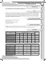
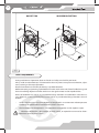
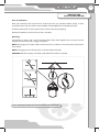
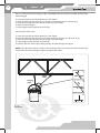
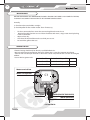
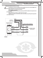
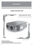
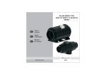
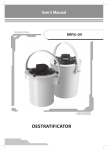
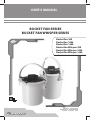
USER’S MANUAL
BUCKET FAN SERIES
BUCKET FAN WHISPER SERIES
Bucket Fan 420
Bucket Fan 1055
Bucket Fan 1460
Bucket Fan Whisper 420
Bucket Fan Whisper 1055
Bucket Fan Whisper 1460
2
Bucket Fan
CONTENT
INTRODUCTION
3
USE
3
WHAT’S INCLUDED IN THE BOX
3
DESIGNATION KEY EXAMPLE
3
SIZE RANGES
3
SAFETY REQUIREMENTS
4
MOUNTING AND INSTALLATION GUIDELINES
5
BUCKET FAN PARTS
7
MAINTENANCE
8
WIRING THE FAN
8
TROUBLESHOOTING
11
STORAGE
11
WARRANTY
12
3
INTRODUCTION
This manual will provide you with installation, operation, and service instructions, as well as technical
data of the Bucket Fan series and Bucket Fan Whisper series.
USE
Bucket Fans are used for equalizing the floor-to-ceiling temperature. This provides a more comfortable
thermal environment for occupants, while at the same time reducing energy costs. In the cold months
the overheated air at the roof is gently directed to the floor where it is needed and wanted. During the
warm months for buildings that are air conditioned, Bucket Fans help push the cold air coming from
the registers at the ceiling to occupant level.
WHAT’S INCLUDED IN THE BOX
One Bucket Fan or Bucket Fan Whisper
One Users Manual
One set of Hanging/Safety Gripples
Controller (if ordered)
DESIGNATION KEY EXAMPLE
Bucket Fan 420 – air destratification fan producing 420 CFM
Bucket Fan Whisper 420 – air destratification fan with isolated casing producing 420 CFM
SIZE RANGES
Dimensions [inches]
Model
A
H
H1
Bucket Fan 420
15 3/16
20 3/16
Bucket Fan 1055
17 1/4
23 7/8
Bucket Fan 1460
19 3/16
Bucket Fan Whisper 420
17 15/16
Bucket Fan Whisper 1055
19 15/16
27 5/8
20 3/8
17 1/16
13 7/8
Bucket Fan Whisper 1460
21 7/8
30 9/16
22 3/8
19 1/16
15 13/16
Weight
[lbs]
D
D1
15 3/16
13 7/16
10 3/16
12
17 15/16
15 7/16
12 3/16
15.2
27 5/16
20 5/16
17 3/8
14 3/16
20.3
24 5/8
18 7/16
15 1/8
11 7/8
24.3
32
37.5
Bucket Fan 420
Bucket Fan Whisper 420
Bucket Fan 1055
Bucket Fan Whisper 1055
Bucket Fan 1460
Bucket Fan Whisper 1460
Volts [V / 60 Hz]
120
120
120
Max. watts
60
94
162
Max. Amps
0.51
0.8
1.38
Air flow [CFM]
420
1055
1460
1700
1675
1685
140
140
140
Model
RPM
Max.operating temp.[ F]
0
4
Bucket Fan
BUCKET FAN
WHISPER BUCKET FAN
Fig. 1
SAFETY REQUIREMENTS
During installation and operation, observe all codes and safety standards for your locale.
Always make sure the electricity is disconnected at the main power source prior to connection, adjustment, servicing and/or repair operations.
Electrical connections should only be done by a qualified electrician.
Before connecting and powering up the Bucket Fan make sure that the unit is free of visible damage and
there are no foreign objects inside the unit that can damage the motor and/or impeller blades.
Misuse of the Bucket Fan and/or any unauthorized design alterations or modifications voids the warranty. VENTS US assumes no liability for misuse or and/or any unauthorized design alterations or modifications.
•
Under no circumstances should the Bucket Fan be operated in an environment with temperatures
exceeding the specifications indicated on the motor name plate.
•
The fan should never be operated in area where there are hazardous and/or explosive vapors .
Whenever a Bucket fan is first installed, serviced, moved, or repaired the unit must be disconnected from the main power source.
5
MOUNTING AND
INSTALLATION GUIDELINES
Prior to Installation:
Read and understand this entire manual. Should you have any questions before, during, or after
installation please call your seller or contact VENTS at 888-640-0925 or [email protected].
Check the product for any damage that may have occurred during shipping.
Rotate the impeller by hand to ensure it turns smoothly.
Mounting
The Bucket Fan comes with a set of Hanging/Safety Cables with Gripples. The set consists of two
Gripples and two cables with a toggle on one end.
NOTE: The Hanging and Safety Cables are the exact same, so there is no need to worry about which
one is which.
NOTE: The toggle ends are the ones that are inserted into the handle.
WARNING: Both the Hanging and Safety cables MUST be installed as directed.
Fig. 2 . Attaching the Bucket Fan with the Hanging Cable and Gripple.
6
Bucket Fan
Tip: It is easier to attach the Hanging Cable and Gripple to the structure first and then attach the fan
with the toggle.
1) Insert the cable into one of the openings in the Gripple
2) Place the cable over the I-beam, truss, or other structure from which it is being hung.
3) Insert the end of the cable into the other opening in the Gripple.
4) Adjust to desired height
5) Insert toggle into the top hole on the handle.
Attaching the Safety Cable
1) Insert the cable into one of the openings in the Gripple
2) Place the cable over the I-beam, truss, or other attaching structure at a 400 to 500 angle
3) Insert the end of the cable into the other opening in the Gripple.
4) Insert toggle into the top hole on the handle.
5) Take the slack out of the safety cable by pulling the cable through the Gripple.
NOTE: The cable should not be so tight as to be pulling the fan to one side. The cable should not be
so loose that the cable could get caught or tangled in the motor.
Safety
Cable
Hanging
Cable
Fig. 3
7
The Bucket Fan can be angled if needed. All
it takes is a 13 mm socket wrench. Loosen the
bolts on either side of the fan, place at the angle
you want, then re-tighten the bolts.
Fig. 4
1
BUCKET FAN PARTS
Bucket Fan
4
1) Electrical junction box on protective grille.
2) Vibration absorbing mount
3) Metal case
4) Handle
5) Handle bolts
6) Casing
7) Sound-Insulation Layer
8) Airflow Straightener
9) Wing Head bolt
5
2
3
Bucket Fan Whisper
9
6
7
8
Fig. 5
The destratificator (see Fig. 5) consists of an
axial fan attached to the casing via the vibration
mounts. The destratificator has a polymer coated
steel casing.
The destratificator is equipped with a singlephase asynchronous motor with an external
rotor and an axial impeller. The motor is
equipped with built-in thermal protection
enabling its automatic restarting and utilizes
rolling-element bearings. The motor protection
class is IP 44.
The Bucket Fan Whisper casing has special
perforation and a sound-insulating layer of
mineral wool to reduce the noise generated
by the axial fan. The Bucket Fan Whisper
destratificator has a flow straightener at the
discharge which ensures direct air flow and
maximum air throw distance.
The destratificator is mounted by means of the
bow bracket (Bucket Fan Whisper can be fixed
with 15° steps) as well as the mounting and the
safety cables with threaded joints.
8
Bucket Fan
MAINTENANCE
BEFORE PERFORMING ANY MAINTENANCE ALWAYS ENSURE THAT THERE IS NO POWER TO THE FAN,
YOU MUST DISCONNECT THE ELECTRICITY AT THE MAIN POWER SOURCE!
Annually:
1) Check to make sure the bolts are tight.
2) Check impeller for dirt or other matter. Clean if necessary.
•
•
To clean, remove the four screws that secure the grille to the metal case.
Remove the grille from the case and clean the blades with warm, soapy water. Avoid splashing
water on the motor.
Wipe surfaces dry.
Also clean the inside of the metal case while you are at it.
Re-attach the grille to the case.
•
•
•
WIRING THE FAN
• Electrical wiring should only be done by a qualified electrician.
• Warranty will not cover equipment damage or failure that is caused by improper installation.
• If the fan did not come pre-wired or if a new wire is to be used, wire the fan as shown in the Figure
6 below.
• Use 18 AWG or greater wire.
1.0 A
Bucket Fan 420
Bucket Fan Whisper 420
Bucket Fan 1055
Bucket Fan Whisper 1055
1.0 A
Bucket Fan 1460
Bucket Fan Whisper 1460
2.0 A
Motor terminal box
Motor run capacitor
C1
X1
BLACK (LINE)
GREEN (PROTECTIVE EARTH)
WHITE (NEUTRAL)
~120 VAC 60 Hz
Fig. 6
9
CONTROLLER WIRING AND INSTALLATION
• The following is for the installation of one controller for one fan. Contact VENTS US if
you need to operate two or more fans with one controller.
• Refer to Figure 7 for electrical connections.
• Use 18 AWG or greater wire.
• It is important that the controller be properly grounded for effective fan operation and
personnel safety.
• Always install the controller in sight of the fan it controls.
• CAUTION: Incorrectly installed fan(s) and/or controller(s) may damage the equipment
and void the warranty.
WHITE
From Fan
GREEN
~120 VAC 60 Hz
BLACK
SPEED CONTROLLER
BOX FOR SPEED CONTROLLER
(pre-installed by user)
RED
WHITE
GREEN
RED
Fig. 7
BLACK
TO POWER SOURCE
~120 VAC 60 Hz
10
Bucket Fan
1. Application
a) Motor Type – Shaded Pole, P.S.C. and Universal.
b) Required Load – Fans, Blowers and Speed Dependent Loads.
2. Wiring
Warning! Power must be turned off before wiring. Connect control in series with motor and line voltage; never connect control across line. Ground (Earth)** – Be sure to ground the control using the
green wire.
**Some models do not require grounding, therefore, a ground wire is not provided.
3. Mounting
a) Use 2” deep standard electrical box.
b) Secure control with outer bracket tabs.
4. Minimum Speed Adjustment
Important: If this option is not supplied, disregard Step 4 and continue to Step 5. This control was designed to operate on motors used in diverse applications. A minimum speed adjustment is provided
to allow independent control of the minimum speed setting. Minimum speed adjustment ensures
motor runs with sufficient torque to prevent stalling.
a) Motor must be in actual operating condition to achieve proper speed adjustment. Motor will
not slow down unless proper load is applied.
b) Turn main control knob to lowest speed position.
c) Locate and adjust minimum speed setting on front plate with screw driver (rotate clockwise to
decrease minimum speed; counter-clockwise to increase minimum speed).
Special Note: For 2.5 and 3.0 Amp models, adjustment of minimum speed is reversed. Rotate
clockwise to increase minimum speed; counter-clockwise to decrease minimum speed.
On some models minimum speed adjustment hole is located on side of control.
d) Motor will now operate from this preset minimum speed to full speed.
11
Connection Diagram 2-Wire* Controls for No Switch Model (NS)
Connection Diagram for 2-Wire* Controls (Switch Models)
L1
L1
Switch
Triac
AC Line
Green
Green
Triac
AC Line
Motor
Motor
Ground (Earth)**
Ground (Earth)**
L2
L2
Connection Diagram for 4-Wire* Controls
Connection Diagram for 3-Wire* Controls (Switch Models)
Full Voltage
Black
Blue***
AC Line
Green
Switch
Ground (Earth)**
L2
L1
Triac
Auxiliary
Load
Red
Black
Variable
Voltage
240 Volt
Red
L2
Motor
Red
Motor
Black
Green
L1
Ground (Earth)**
*** Wire may be white in some applications
* Ground wire is not counted when designating 2,3 or 4 wire controls.
** Be sure to ground control using the green wire. Some models do not require grounding, therefore, a ground wire is
not provided.
*** Wire may be white in some applications.
Fig. 8
TROUBLESHOOTING
Model
The fan does not start
The fan does not start (possibly with humming noise)
Loud noise, vibration
Possible reason
Remedy
No power
Have a qualified electrician check
connections and power source.
Object stuck in blades
Turn off power. Remove object.
Restart fan.
Loose screw
Dirty impeller
Tighten screw
Clean the unit according to directions in this manual.
Please call Customer Service at 888-640-0925 with any other problems encountered.
STORAGE
Should you need to store the fan for any length of time:
•
Store the fan in its original packaging in a ventilated area. Temperatures should not be below 41
or higher than 104 F. Humidity should not be above 80%.
•
The fan must be stored in a non-corrosive environment.
•
Avoid storing the fan in an area where it may be hit by a forklift, where it will have to be moved
a number of times, etc.
12
Bucket Fan
WARRANTY
VENTS US warrants to the original purchaser of the Bucket Fan Series series fan that it will be free from
defects in materials or workmanship for a period of 60 months from the date of original purchase.
If the fan is installed with the speed controller the warranty period is decreased to 24 months.
THERE ARE NO OTHER WARRANTIES, EXPRESS OR IMPLIED, INCLUDING, BUT NOT LIMITED TO, IMPLIED
WARRANTIES OF MERCHANTABILITY OR FITNESS FOR A PARTICULAR PURPOSE. During the stated
warranty period, VENTS US will, at its option, repair or replace, without charge, any product or part
which is found to be defective under normal use and service. This warranty does not cover (a) normal
maintenance and normal service or (b) any products or parts which have been subject to misuse,
negligence, accident, improper maintenance or repair (other than by VENTS US), faulty installation or
installation contrary to recommended installation instructions. Labor to remove and replace products
is not covered. The duration of any implied warranty is limited to the time period specified for the
express warranty. Some states do not allow limitations on how long an implied warranty lasts, so the
above limitation may not apply to you. VENTS US OBLIGATION TO REPAIR OR REPLACE, AT VENTS US
OPTION, SHALL BE THE PURCHASER’S SOLE AND EXCLUSIVE REMEDY UNDER THIS WARRANTY. VENTS
SHALL NOT BE LIABLE FOR INCIDENTAL, CONSEQUENTIAL OR SPECIAL DAMAGES ARISING OUT OF
OR IN CONNECTION WITH PRODUCT USE OR PERFORMANCE. Some states do not allow the exclusion
or limitations of incidental or consequential damages, so the above limitation or exclusion may not
apply to you. This warranty gives you specific legal rights, and you may also have other rights which
vary from state to state. This warranty supersedes all prior warranties.
V96EN-03(USA_120)