1
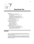
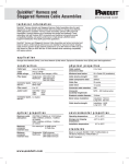
FROM TME-C005A, 16/9/99
Points to Observe for Safe Usage
R
R
VPE-B005
• Read this manual carefully before starting operation and use this system safely. We
cannot be responsible for problems resulting from failure to observe the instructions in
this manual.
• This manual uses various pictorial displays to show how to use this product safely
and to avoid harm to yourself and others and damage to your property. Here is what
these pictorial displays mean. Understanding them is important for reading this
manual.
• Meaning of displays
This symbol means important instructions.
WARNING Failure to heed them can result in serious injury or death.
Monitor Interface Box
CAUTION
(for use with NVE-N851A only)
OWNER'S MANUAL
Please read before using this equipment.
This symbol means important instructions.
Failure to heed them can result in injury or property damages.
WARNING
DO NOT DISASSEMBLE OR ALTER. Doing so may result in an accident, fire or
electric shock.
BRIGHT
USE THIS PRODUCT FOR MOBILE 12V APPLICATIONS. Use for other than its
designed application may result in fire, electric shock or other injury.
POWER SUPPLY
MAKE THE CORRECT CONNECTIONS. Failure to make the proper connections may
result in fire or product damage.
DISPLAY OUTPUT
USE ONLY IN CARS WITH A 12 VOLT NEGATIVE GROUND. (Check with your dealer
if you are not sure.) Failure to do so may result in fire, etc.
NAVIGATION INPUT
MONITOR INTERFACE BOX
VPE-B005
BEFORE WIRING, DISCONNECT THE CABLE FROM THE NEGATIVE BATTERY
TERMINAL. Failure to do so may result in electric shock or injury due to electrical
shorts.
DO NOT ALLOW CABLES TO BECOME ENTANGLED IN SURROUNDING OBJECTS.
Arrange wiring and cables in compliance with the manual to prevent obstructions when
driving. Cables or wiring that obstruct or hang up on places such as the steering wheel,
gear lever, brake pedals, etc. can be extremely hazardous.
SERIAL NUMBER:
INSTALLATION DATE:
INSTALLATION TECHNICIAN:
PLACE OF PURCHASE:
ALPINE ELECTRONICS, INC.
Tokyo office: 1-1-8 Nishi Gotanda,
Shinagawa-ku, Tokyo 141-8501, Japan
Tel.: (03) 3494-1101
ALPINE ELECTRONICS OF AMERICA, INC.
19145 Gramercy Place, Torrance,
California 90501, U.S.A.
Tel.: 1-800-ALPINE-1(1-800-257-4631)
ALPINE ELECTRONICS OF CANADA, INC.
Suite 203, 7300 Warden Ave. Markham,
Ontario L3R 9Z6, Canada
Tel.: 1-800-ALPINE-1(1-800-257-4631)
68P30540Y21-O
Printed in Japan (S)
In Case of Difficulty
If you encounter a problem, please review the items in the following check list. This
guide will help you isolate the problem if the unit is at fault. Otherwise, make sure the
rest of your system is properly connected or consult your authorized Alpine dealer.
Symptom
No function or
display.
No picture display.
Poor picture
brightness.
Cause
Solution
Car's ignition is off.
Turn the ignition on.
Incorrect connections.
Check connection and remedy.
Vehicle's battery is weak.
Check the voltage of vehicle's
battery.
No fuse or blown fuse.
Check the cause and replace
the fuse.
Brightness control is set for
minimum brightness level.
Adjust the brightness.
Incorrect or open connection.
Check the connection and
remedy.
Brightness control is not set at
the correct level.
Check each control.
DO NOT SPLICE INTO ELECTRICAL CABLES. Never cut away cable insulation to
supply power to other equipment. Doing so will exceed the current carrying capacity of
the wire and result in fire or electric shock.
DO NOT DAMAGE PIPE OR WIRING WHEN DRILLING HOLES. When drilling holes in
the chassis for installation, take precautions so as not to contact, damage or obstruct
pipes, fuel lines, tanks or electrical wiring. Failure to take such precautions may result in
fire.
DO NOT USE BOLTS OR NUTS IN THE BRAKE OR STEERING SYSTEMS TO MAKE
GROUND CONNECTIONS. Bolts or nuts used for the brake or steering systems (or any
other safety-related system), or tanks should NEVER be used for installations or ground
connections. Using such parts could disable control of the vehicle and cause fire etc.
KEEP SMALL OBJECTS SUCH AS BOLTS OR SCREWS OUT OF THE REACH OF
CHILDREN. Swallowing them may result in serious injury. If swallowed, consult a
physician immediately.
CAUTION
HALT USE IMMEDIATELY IF A PROBLEM APPEARS. Failure to do so may cause
personal injury or damages to the product. Return it to your authorized Alpine dealer or
the nearest Alpine Service Center for repairing.
HAVE THE WIRING AND INSTALLATION DONE BY EXPERTS. The wiring and
installation of this unit requires special technical skill and experience. To ensure safety,
always contact the dealer where you purchased this product to have the work done.
USE SPECIFIED ACCESSORY PARTS AND INSTALL THEM SECURELY. Be sure to
use only the specified accessory parts. Use of other than designated parts may damage
this unit internally or may not securely install the unit in place. This may cause parts to
become loose resulting in hazards or product failure.
ARRANGE THE WIRING SO IT IS NOT CRIMPED OR PINCHED BY A SHARP
METAL EDGE. Route the cables and wiring away from moving parts (like the seat rails)
or sharp or pointed edges. This will prevent crimping and damage to the wiring. If wiring
passes through a hole in metal, use a rubber grommet to prevent the wires' insulation
from being cut by the metal edge of the hole.
DO NOT INSTALL IN LOCATIONS WITH HIGH MOISTURE OR DUST. Avoid installing
the unit in locations with high incidence of moisture or dust. Moisture or dust that
penetrates into this unit may result in product failure.
Specifications
Power requirement ............................................................ 10 – 16V DC negative ground
Dimensions (W x H x D) .................................................... 73.4mm x 28.2mm x 117.8mm
(2-7/8" x 1-1/8" x 4-5/8")
Weight .............................................................................................................. 210g (7 oz)
Installation
1
To avoid unnecessary signal wiring, it is better to mount the Unit as close as possible to the NVE-N851A.
DO NOT MOUNT THE UNIT IN LOCATIONS THAT WILL BE IN THE VICINITY OF MOISTURE OR EXTREME
HEAT (such as the engine compartment).
The Unit can be mounted by using self-tapping screws or Velcro™ tape. Make sure you have all the necessary
parts and tools. Then, begin mounting according to one of the following procedures:
3
Screw-down Mounting (Fig. 1):
1. Using the unit as a template, hold it at its mounting location and mark the holes to be drilled. Before drilling,
make sure that there are no objects that could be damaged behind the mounting surface.
2. Drill holes and secure the unit with self-tapping screws (M4 x 14) supplied.
4
2
Fig. 1
Fig. 2
Velcro™ Tape Mounting (Fig. 2):
This installation method is suggested when the mounting location does not permit drilling.
USE THIS METHOD ONLY WHEN THE UNIT IS MOUNTED ON A HORIZONTAL SURFACE. NEVER MOUNT A
UNIT UPSIDE-DOWN USING THE VELCRO™ TAPE.
1. Remove the adhesive protective paper from one side of the Velcro™ tape.
2. Attach the exposed adhesive side to the underside of the Unit, in a central location. Do not cover the serial number.
3. Make sure the mounting location is clean, dry and free from contaminants.
4. Remove the protective strip from the other side of the Velcro™ pad.
5. Press the unit onto its mounting location.
Numbers Identification
1 Self-Tapping Screws (M4 x 14) (Included)
2 Floor/Trunk
3 Velcro™ Tape (Included)
4 Press onto the carpet.
Connection
TME-C005AS
LCD COLOR NAVIGATION MONITOR TME-C005AS
POWER
Battery Lead (Yellow)
(5A)
GPS RECEIVER
CD-ROM DRIVE
LIST
CANCEL
M/G
GYROSCOPE
BATTERY
N/H
ZOOM/PAGE
VOICE
MENU
ENTER
Acc (Ignition) (Red)
PLAN
DTR
To the Acc power lead
(5A)
Ground (Black)
Connect to a metal part of
chassis body with screw.
Dimmer In (Illumination) (+) (White/Blue)
Optional
KWE- 660N
To the illumination signal line
Parking Brake (Yellow/Blue)
To the parking brake signal line
Reverse (+) (Orange/White)
To reverse lights (+12V signal)
Speed Sensor (Green/White)*
Connect to VSS (Digital or Analog 0V – 3V)
To the vehicle speed pulse line
BRIGHT
DISPLAY OUTPUT
MONITOR INTERFACE BOX
Mute (Pink/Skyblue)
To audio head unit MUTE wire or
Alpine "IN-INT" function wire
*
POWER SUPPLY
NAVIGATION INPUT
VPE-B005
Improper connection of the speed pulse line
may cause important safety features of the
vehicle to fail (such as the brakes or air bag).
Such failures may result in an accident and
loss of life. We strongly recommend that the
installation be performed by a trained,
authorized Alpine dealer.
** The power supply cable supplied with the
NVE-N851A is not used.
Note: Make the connections and adjustments
by referring to the Manual for the product
to be connected.
(4pin)
13P RGB Extension Cable Included
Power supply cable
(10 pin)
MIC/SW
TO DISP.
EX-1
EX-2
POWER
GPS ANT.
NVE-N851A**
Adjusting Brightness of Monitor
The brightness of TME-C005AS connected is adjusted from this unit.
Adjust by turning the knob to obtain a preferrable brightness.