1
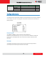
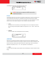
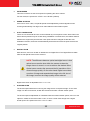
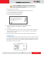
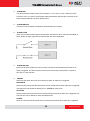
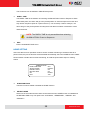
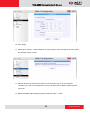
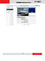
TCM-6630 36x Zoom H.264 IP D/N Outdoor Speed Dome Hardware User’s Manual Ver. 2012/6/25 TCM-6630 Hardware User’s Manual Table of Contents 0. Precautions 4 1. Introduction 5 Package Contents ........................................................................... 5 Features and Benefits ..................................................................... 6 Safety Instructions .......................................................................... 8 Physical description ........................................................................ 9 2. Installation Procedure 14 Installing Speed Dome Cover ....................................................... 14 1) Remove the Plastic Protection cap ..................................... 14 2) Apply Lubricant to clear cover ............................................ 14 3) Attach clear cover to speed dome ...................................... 15 Connecting cables......................................................................... 16 Network Connection .................................................................... 18 Mounting Options for Speed Dome ............................................. 19 Wall .............................................................................................. 19 Corner .......................................................................................... 22 Pole .............................................................................................. 24 Ceiling .......................................................................................... 26 3. Appendix 27 OSD Menu Notes (On Screen Display) .......................................... 27 OSD Display Format .................................................................... 27 OSD Setup Menu ......................................................................... 27 Configuration Menu ..................................................................... 30 Default Camera ............................................................................ 30 Backlight ...................................................................................... 30 FOCUS ........................................................................................ 31 2 www.acti.com TCM-6630 Hardware User’s Manual APERTURE.................................................................................. 31 AE MODE .................................................................................... 32 WBC MODE ................................................................................. 32 ID DISPLAY.................................................................................. 33 SETUP MENU ............................................................................. 34 TITLE DISPLAY ........................................................................... 36 TITLE SETTING ........................................................................... 36 ALARM SETTING ........................................................................ 37 HOME SETTING .......................................................................... 39 SEQENCE ................................................................................... 40 AUTOPAN .................................................................................... 42 CRUISE........................................................................................ 43 IR FUNCTION (Removable IR Cut).............................................. 44 WDR SETTING ............................................................................ 45 PRIVACY...................................................................................... 46 TIME FUNCTION ......................................................................... 48 EXIT OSD .................................................................................... 48 Product Specification .................................................................... 49 4. Accessing Camera 51 If you have DHCP server / router in your network: ...................... 51 If you do NOT have DHCP server / router in your network: ......... 51 3 www.acti.com TCM-6630 Hardware User’s Manual 0. Precautions Read these instructions You should read all the safety and operating instructions before using this product. Heed all warnings You must adhere to all the warnings on the product and in the instruction manual. Failure to follow the safety instruction given may directly endanger people, cause damage to the system or to other equipment. Servicing Do not attempt to service this video device yourself as opening or removing covers may expose you to dangerous voltage or other hazards. Refer all servicing to qualified service personnel. Trademarks All names used in this manual are probably registered trademarks of respective companies. Liability Every reasonable care has been taken during the writing of this manual. Please inform your local office if you find any inaccuracies or omissions. We cannot be held responsible for any typographical or technical errors and reserve the right to make changes to the product and manuals without prior notice. FCC/CE Regulation NOTE: This equipment has been tested and found to comply with the limits for a Class A digital device, pursuant to Part 15 of the FCC Rules. These limits are designed to provide reasonable protection against harmful interference when the equipment is operated in a commercial environment. This equipment generates, uses, and can radiate radio frequency energy and, if not installed and used in accordance with the instruction manual, may cause harmful interference to radio communications. Operation of this equipment in a residential area is likely to cause harmful interference in which case the users will be required to correct the interference at their own expense. 4 www.acti.com TCM-6630 Hardware User’s Manual 1. Introduction Package Contents TCM-6630 Network Cable Power Adaptor Power, Audio and Video Cable Alarm Cable Waterproof Rubber Sleeve & Mounting Kit Product CD Accessories (Lubricant / Screws) Warranty Card 5 www.acti.com TCM-6630 Hardware User’s Manual Features and Benefits The IP High Speed Dome is designed to deliver superb performance and durability with an intelligent and stylish housing. It also provides a reliable real time images with outstanding image quality (D1, 720x480). It can compress and transmit real time images with outstanding image quality (30 FPS @ D1, 720 x 480 or 720 x 576) through a standard TCP/IP network. This camera is your best choice to build an intelligent IP surveillance system. High Speed Pan-Tilt and Zoom This High Speed Dome is available: 36x MODEL: 36x optical zoom plus 12x digital magnifier/D&N/WDR Precise and Accurate Tracking Scheduling function, a special feature, enables users to program a preset point or patrol sequence. This IP high speed dome provides variable pan/tilt speed ranging from a fast patrol of 400° per second to a slow ramble of 5° per second with 0.225° pan accuracy for fast and accurate tracking ability. The 360° endless rotation and -10°~190° tilt travel makes tracking the object passing directly beneath the dome very easy. Maximum 256 preset points can be programmed for precise location of target areas, and you may also define 8 patrol sequences, 4 auto-pan sets and 1 cruise rotation for the camera to operate automatically. Day/Night Features Mechanically Removable IR cut filter ensures 24 hours operation. Low-Light Application Digital Slow Shutter and Electronic Shutter functions are provided for clear and high quality image. The minimum illumination is 0.01 Lux. Perfect Contrast Solution for High Image Quality Wide Dynamic Range function is an important feature incorporated to fit your needs Privacy Mask for Privacy Protection There are up to 24 configurable privacy zones. This is specially designed to avoid any intrusive monitoring at specific regions. 6 www.acti.com TCM-6630 Hardware User’s Manual H.264/MPEG-4/MJPEG Triple Codec Dual Streaming This device supports 3 compression formats, H.264, MPEG-4 and MJPEG. It brings superior image quality at 30 frames per second up D1 resolution (720 x 480 pixels). Built-in Hardware Motion Detection No more external motion sensors are required. You may assign up to 3 video motion detection areas. By tuning the object size and sensitivity, it will reliably detect objects passing though in view. Hardware motion detection also offers better sensitivity and faster response time than software motion detection. Powerful Bundled Surveillance Software To extend the capabilities of the IP Camera, a powerful surveillance program is included in the package for free. Users can easily use an existing PC as a digital video recorder. Scheduled recording and manual recording keep every important video recorded in the local hard disk. Reliable and accurate motion detection with instant warning enables immediate response in every condition. Quick and simple search and playback function lets you easily find the images and video you want. Software Development Kit Support This IP Camera can be integrated or controlled by applications from third party software developers. Software developers can save considerable efforts by using our Streaming Library or ActiveX control. Please contact us for details on integration support. Digital Time Code Embedded The “Digital Time Code Embedded” function records video time in the video stream. Therefore, each image frame is marked with its original recording time. It is very useful when users want to find the video at an exact time or between a certain time intervals. 7 www.acti.com TCM-6630 Hardware User’s Manual Safety Instructions Don’t use the power supply with other voltages This device is likely to be damaged or damage other equipments / personnel, if you use a power supply with different voltage than the one included with this device. All warranty of this product will be voided in the situations above. Cleaning Disconnect this video product from the power supply before cleaning. Attachments Do not use attachments not recommended by the video product manufacturer as they may cause hazards. Water and Moisture Do not use this video product near water, for example, near a bathtub, washbowl, kitchen sink, or laundry tub, in a wet basement, or near a swimming pool and the like. Servicing Do not attempt to service this video product yourself as opening or removing covers may expose you to dangerous voltage or other hazards. Refer all servicing to qualified service personnel. Damage Requiring service Disconnect this video product from the power supply immediately and refer servicing to qualified service personnel under the following conditions. 1) When the power-supply cord or plug is damaged 2) If liquid has been spilled, or objects have fallen into the video product. 3) If the video product has been directly exposed to rain or water. 4) If the video product does not operate normally by following the operating Instructions in this manual. Adjust only those controls that are covered by the instruction manual, as an improper adjustment of other controls may result in damage, and will often require extensive work by a qualified technician to restore the video product to its normal operation. Safety Check Upon completion of any service or repairs to this video product, ask the service technician to perform safety checks to determine if the video product is in proper operating condition. 8 www.acti.com TCM-6630 Hardware User’s Manual Physical description 1) Reset Button Step 1: Switch off IP device by disconnecting the power cable Step 2: Press and continue to hold the Reset Button (with a sharp tipped object, like a pen.) Step 3: Reconnect the power cable while continuing to hold the reset button for 20 seconds. By this time the reset to default operation is already completed. You may then release the reset button. This length of time fluctuates slightly with the environment. The Power LED light will come back on and stay on after a few more seconds. The unit will start up with factory default settings automatically. 9 www.acti.com TCM-6630 Hardware User’s Manual 2) Dome Control Protocol To control PTZ action of this Speed Dome, the control protocol of your software must match the one used by the Speed Dome Camera. The protocol setting is only available on “07 - DSCP (Dynacolor)” baud rate 9600 by using firmware v4.12.09 or above version. Please make sure to turn the switch to the proper number (07). decimal single digit 3) Ethernet Port The IP device connects to the Ethernet via a standard RJ45 connector. Supporting NWAY, this IP device can auto detect the speed of local network segment (10Base-T/100Base-TX Ethernet). 4) 22 pin connector for Power / Audio In / Audio Out / Video Out / DIO This 50 cm cable consolidates all these wires to a single connection. Power Input / Audio In / Audio Out / Video Out are pre-connected. For DIO, there is a separate cable that you may insert into the 22 pin connector. Please reference the table below for pin definitions Pin Definition Cable 1 AC 24-1/DC(+) 20 AWG 2 ALM NC 3 AC 24-1/DC(-) 4 ALM NO 5 FG 6 ALM COM 20 AWG 20 AWG 10 www.acti.com TCM-6630 Hardware User’s Manual 7 MIC + 8 SPK + 9 MIC - 10 SPK - 11 ISOG 12 ALM-1 13 ALM-3 14 ALM-2 15 ALM-4 16 ALM-5 17 ALM-6 18 ALM-7 19 ALM-8 20 ALM GND 21 VGND 22 Video 24 AWG 24 AWG Please see the graph below on how to insert terminals to connector housing. 11 www.acti.com TCM-6630 Hardware User’s Manual 5) Dome ID Setting Use the switch to change your speed dome ID by turning the arrow to change each digit to the desired number. For instance, if the Speed dome ID is 123, the ID switch should be set as below: NOTE: If controlling through an ACTi decoder via analog means such as a keyboard or DVR, no two speed domes should be given the same ID or communication conflict may occur. When controlled only through Ethernet and software (without the use of an ACTi hardware decoder), the dome ID setting may be ignored. 12 www.acti.com TCM-6630 Hardware User’s Manual 6) Communication Switch Setting The table below shows the function of each pin within the Communication Switch Communication Switch Pin 1 Pin 2 RS-232 Setting (Reserved) Pin 3 Termination Pin 4 Line Lock Pin 5 System Initialization (for upgrade) Pin 6 Reserved RS-232 is reserved for internal use only; The Pin 3 and Pin 4, they are used for termination and Link Lock adjustment respectively. The Pin 5 is mainly used for return to factory default of camera setting. 7) Suspension Loop This metal cable loop is used to suspend Speed dome from mounting accessories during installation so that it does not fall down by slipping. 13 www.acti.com TCM-6630 Hardware User’s Manual 2. Installation Procedure Installing Speed Dome Cover 1) Remove the Plastic Protection cap Remove the plastic protection cap from the speed dome unit. 2) Apply Lubricant to clear cover Apply lubricant included in package to dome cover rubber sleeve. This helps ease installation 14 www.acti.com TCM-6630 Hardware User’s Manual 3) Attach clear cover to speed dome There are a few micro-steps involved here. First you need to find the plastic stud by the side of dome cover. Insert that into one of the slots at the side of speed dome. Secondly, there are two metal screws at the sides of the dome cover. Use a flat headed screwdriver and unscrew them. Unscrewing will extend them outwards, securing the dome cover. 15 www.acti.com TCM-6630 Hardware User’s Manual Lastly use the small screw included in package to lock the dome cover into position. Connecting cables When installing, please note that you should string the cable through the accessories, the rubber waterproof sleeve, the mount kit and then into the ports. Please see image below for sequence. 16 www.acti.com TCM-6630 Hardware User’s Manual There are three locking areas on the mount kit. Put it on top of the speed dome, then rotate it into position. Once it is rotated into position, you may use the other larger screw to keep it in place. 17 www.acti.com TCM-6630 Hardware User’s Manual Network Connection Follow the diagram below to connect the IP high speed dome to the respective devices. 18 www.acti.com TCM-6630 Hardware User’s Manual Mounting Options for Speed Dome Wall Heavy Duty Wall Mount PMAX-0309 Heavy Duty Wall Mount + Junction Box PMAX-0309 + PMAX-0700 19 www.acti.com TCM-6630 Hardware User’s Manual Gooseneck Wall Mount - Raised PMAX-0307 Gooseneck Wall Mount - Flat PMAX-0306 20 www.acti.com TCM-6630 Hardware User’s Manual Gooseneck Wall Mount + Junction Box PMAX-0306 + PMAX-0700 21 www.acti.com TCM-6630 Hardware User’s Manual Corner Heavy Duty Corner Mount PMAX-0309 + PMAX-0402 Heavy Duty Corner Mount + Junction Box PMAX-0309 + PMAX-0402 + PMAX-0700 22 www.acti.com TCM-6630 Hardware User’s Manual Gooseneck Corner Mount PMAX-0306 + PMAX-0402 Gooseneck Corner Mount + Junction Box PMAX-0306 + PMAX-0402 + PMAX-0700 23 www.acti.com TCM-6630 Hardware User’s Manual Pole Heavy Duty Pole Mount PMAX-0309 + PMAX-0502 Heavy Duty Pole Mount + Junction Box PMAX-0309 + PMAX-0700 + PMAX-0502 24 www.acti.com TCM-6630 Hardware User’s Manual Gooseneck Pole Mount PMAX-0306 + PMAX-0502 Gooseneck Pole Mount + Junction Box PMAX-0306 + PMAX-0700 + PMAX-0502 25 www.acti.com TCM-6630 Hardware User’s Manual Ceiling Pendant Mount PMAX-0109 Pendant Mount + Junction Box PMAX-0108 + PMAX-0700 ** If your camera need to be located far below the mounting point, please use PMAX-0104 extension tube. 26 www.acti.com TCM-6630 Hardware User’s Manual 3. Appendix OSD Menu Notes (On Screen Display) OSD Display Format The information shown on the screen are described in terms of OSD display, position and function description in the table below. 1 3 2 4 6 5 Position Function 1 Focus Modes 2 Backlight 3 Alarm 4 Zoom Ratio 5 Title 6 Camera ID OSD Display Description A Auto Focus Mode M Manual Focus Mode X Back Light Compensation OFF B Back Light Compensation ON ALARM Alarm Message Present Zoom Ratio ×1 (Optical Zoom(Digital Zoom) Maximum 20 characters for each title. 16 sets of title are available. Show the camera ID OSD Setup Menu The OSD setup menu structure is listed separately in the following section. The star symbol indicates the factory default. 27 www.acti.com TCM-6630 Hardware User’s Manual TCM-6630: Item Layer 1 DEFAULT CAMERA <ON>, <OFF> BACKLIGHT ON OFF AUTO FOCUS APERTURE AE MODE WBC MODE ID DISPLAY SETUP MENU TITLE DISPLAY TITLE SETTING MANUAL AUTO MANUAL AUTO SHUTTER IRIS AGC AUTO MANUAL <ON>, <OFF> FLIP ZOOM SPEED SPEED BY ZOOM AUTO CALI. DIGITAL ZOOM SLOW SHUTTER (K model only) ANGLE ADJUSTER RESET EXIT <ON>, <OFF> HOME SETTING Layer 3 PRESET POINT SEQUENCE LINE AUTOPAN LINE CRUISE LINE DWELL TIME EXIT HOME FUNC. SELECT MODE Default ON BLC Level <000> ~ <100> Focus Length <1cm>, <10cm>, <30cm> <1m> <01> ~ <08> ☆ 10 cm ☆ H APERTURE <00> ~ <31> V APERTURE <00> ~ <31> IRIS OFFSET <00> ~ <99> SHUTTER SPEED <1/2> ~ <1/30000> IRIS <00> ~ <09> AGC <00> ~ <05> 50 ☆ R Gain <00> ~ <99> B Gain <00> ~ <99> <IMAGE>(K model only), <M.E.>, <OFF> <FAST>, <SLOW> <ON>, <OFF> <ON>, <OFF> <1> ~ <12>, <OFF> <1/2> ~ <1/60> Sec. (NTSC) <1/1.5> ~ <1/50> Sec. (PAL) ADJUST MIN ANGLE ADJUST MAX ANGLE RESET YES ON OFF Slow OFF OFF OFF 1/30 00 90 OFF <01> ~ <16> ALARM PIN ALARM SWITCH ALARM TYPE ALARM ACTION ALARM SETTNG Layer 2 01 <1> ~ <8> <ON>, <OFF> <N.O.>, <N.C.> PRESET SEQUENCE AUTOPAN CRUISE <001> ~ <256> <1> ~ <8> <1> ~ <4> <1> <001> ~ <127> Sec., ALWAYS YES <ON>, <OFF> PRESET SEQUENCE 28 1 OFF N.C. ☆ 001 ALWAYS OFF ☆ www.acti.com TCM-6630 Hardware User’s Manual Item SEQUENCE AUTOPAN CRUISE Layer 1 PRESET POINT SEQUENCE LINE AUTOPAN LINE CRUISE LINE RETURN TIME GO EXIT SEQUENCE LINE SEQUENCE POINT PRESET POS. SPEED DWELL TIME RUN SEQUNECE EXIT AUTOPAN LINE START POINT END POINT DIRECTION SPEED RUN AUTOPAN EXIT RECORD START RECORD END RUN CRUISE EXIT AUTO IR FUNCTION (K model only) ON WDR SWITCH WDR FUNCTION WDR SETTING (K model only) EXIT PRIVACY SWITCH SHADE SET MASK PRIVACY (K model only) TIME MASK CLEAR+RESET MASK DSIPLAY EXIT TIME DISPLAY SET YEAR Layer 2 Layer 3 AUTOPAN CRUISE <001> ~ <256> <1> ~ <8> <1> ~ <4> <1> <001> ~ <128> Min. ENTER YES <1> ~ <8> <01> ~ <32> Default 001 001 1 01 <001> ~ <255>, <END> <01> ~ <15> <000> ~ <127> Sec. ENTER 001 01 000 <1> ~ <4> <TO FIND>, <TO SAVE> <TO FIND>, <TO SAVE> <RIGHT>, <LEFT> <01> ~ <04> ENTER 1 THRESHOLD IR COLOR EXIT <LOW>, <MID>, <HI> <B/W>, <COLOR> Right 01 LOW B/W <ON>, <OFF> AUTO MANUA RATIO LEVEL L <000>~<128> SHUTTER LEVEL <000>~<128> IRIS OFFSET <000>~<128> OFF ☆ <ON>, <OFF> <BLACK>, <WHITE>, <GRAY> <1> ~ H CENTER <000> ~ <256> <8> V CENTER <000> ~ <256> H SIZE <000> ~ <127> V SIZE <000> ~ <127> <01> ~< 08> OFF Gray <FIRST>, <LAST> YES <ON>, <OFF> First 29 01 OFF www.acti.com TCM-6630 Hardware User’s Manual Item Layer 1 EXIT OSD SET MONTH SET DAY SET HOUR SET MINUTE EXIT+SAVE YES Layer 2 Layer 3 Default Configuration Menu The detailed functions and parameter settings of your high speed dome can be set by the OSD (On Screen Display) menu with a control program. The functions in OSD menu are described in the following sections. 36x MODEL MAIN PAGE 1 DEFAULT CAMERA BACKLIGHT FOCUS APERTURE AE MODE WBC MODE ID DISPLAY SETUP MENU OFF OFF AUTO AUTO AUTO AUTO ON ENTER Default Camera The “DEFAULT CAMERA” is used to restore the camera settings (e.g. Backlight/Focus/AE//WBC/Aperture). Once any one of the items is modified, the setting will become <OFF> automatically. Select <ON> for this item to recall the mentioned camera parameters. Backlight The Backlight compensation function prevents the center object from being too dark in surroundings where excessive light is behind the center object. 30 www.acti.com TCM-6630 Hardware User’s Manual The Backlight Compensation Level ranges from 000 to 100. BLC LEVEL LEVEL EXIT 20 YES NOTE: If this function is enabled, the WDR function will be disabled automatically. FOCUS Automatically adjusts the focus position to maximize the high frequency content of the picture in a center measurement area, taking into consideration the high luminance and strong contrast components. The focus of the dome camera can be operated in two modes: Manual Focus mode and Auto Focus mode. Different settings for various models are described as follows. AUTO The optimum focus is achieved by the internal digital circuit. Users can adjust the minimum auto focus range for some special conditions; the options are <1cm>, <10cm>, <30cm> and <1m>. MANUAL In this focus mode, users can adjust the lens focus manually. FOCUS LENGTH TURNING VALUE 10CM EXIT YES APERTURE Sharpness is the subjective evaluation of detail in the picture. With this “APERTURE” function, users can adjust the enhancement of the edges of objects in the picture. When shooting text, this function may help by making them sharper and achieve a better image. There are 32 levels of adjustment, the options are <00> ~ <31>, <00> represents “no enhancement”. AUTO The dome camera will assign a proper aperture value automatically for camera to achieve a better image. 31 www.acti.com TCM-6630 Hardware User’s Manual MANUAL Select this item if you want to adjust aperture value manually. Higher value enhances the incident ray of camera. APERTURE MENU H APERTURE 15 V APERTURE 15 AE MODE The exposure is the amount of light received by the image sensor and is determined by how wide you open the lens diaphragm (iris adjustment), by how long you keep the sensor exposed (shutter speed), and other exposure parameters. With this item, users can define how the Auto Exposure (AE) function works. AUTO In this mode, the camera’s Shutter, IRIS and AGC control function work automatically to compensate the light exposure of image sensor for consistent video output level. IRIS OFF SET is used to set the level of IRIS variation. SHUTTER With this option, the SHUTTER priority is higher than IRIS and AGC; IRIS and AGC circuit will function automatically in cooperating with SHUTTER to get consistent exposure. IRIS With this option, the IRIS priority is higher than SHUTTER and AGC; SHUTTER and AGC circuit will function automatically in cooperating with IRIS to get consistent exposure. If the IRIS is modified manually, the action of exposure compensation depends on the AGC circuit. AGC With this option, the AGC priority is higher than SHUTTER and IRIS; SHUTTER and IRIS circuit will function automatically in cooperating with AGC to get consistent exposure. If AGC is adjusted manually, the exposure compensation depends on the changing of IRIS. WBC MODE A digital camera needs to find reference colour temperature, which is a way of measuring the quality of a light source, for calculating all the other colours. The unit for measuring this ratio is in 32 www.acti.com TCM-6630 Hardware User’s Manual degree Kelvin (K). You can select one of the White Balance Control modes according to the condition. The following table shows the colour temperature of some light sources. Light Sources Color Temperature in K Cloudy Sky 6,000 to 8,000 Noon Sun and Clear Sky 6,500 Household Lighting 2,500 to 3,000 75-watt Bulb 2,820 Candle Flame 1,200 to 1,500 AUTO In this mode, white balance works within its colour temperature range and calculates the best-fit white balance. MANUAL In this mode, users can change the White Balance value manually; adjustable R gain and B gain range from 0 to 99. WBC MENU R GAIN B GAIN 50 50 ID DISPLAY Users are allowed to choose whether the dome ID will be displayed on monitor to identify the domes. ON Display the ID address of the selected dome on the right bottom of the monitor screen. OFF Hide the ID address of the selected dome. 33 www.acti.com TCM-6630 Hardware User’s Manual SETUP MENU Users can adjust camera lens model parameters under SETUP MENUs. Depending on the model of dome cameras, the SETUP MENUs are different. FLIP (IMAGE/ME/OFF) User can track an object continuously when it passes through under dome camera with setting Flip to IMAGE (digital flip) or M.E. (mechanical flip). FLIP SETTING FLIP EXIT OFF YES IMAGE IMAGE represents digital IMAGE FLIP, enables users to keep tracking object seamlessly and no delay occurs in comparing with mechanical flip. NOTE: The Privacy Mask function will be automatically disabled if the Image Flip function is enabled, and “Masking will be disabled” will be displayed on the screen. M.E. The item is a standard mechanical operation. As the dome tilts 9 0°, it will pan 180°, then continuing tilt to keep tracking object. OFF Select this item to disable the flip function. NOTE: The speed dome will only be able to tilt 90°, or -10° ~ 100° with angle adjuster adjustments. 34 www.acti.com TCM-6630 Hardware User’s Manual ZOOM SPEED This item is used to set the zoom speed for operating the dome camera. For this model, the options are <FAST> and <SLOW> (default). SPEED BY ZOOM If the item is set to <ON>, the pan/tilt speed will be adjusted by internal algorithm when zooming automatically. The larger zoom ratio leads the lower rotation speed. AUTO CALIBRATION There are one horizontal and one vertical infrared rays check points in each dome. When the dome camera position may be moved during installation or maintenance, the relative distance between the original set point and the check point has been changed. Enable the Auto Calibration function, the dome will automatically detect that and reset the point baack to the original position. DIGITAL ZOOM With this item, users can enable or disable the 12x Digital Zoom. The Digital Zoom activate after the full Optical Zoom level is reached. NOTE: The difference between optical and digital zoom is that optical zoom uses the lens within the camera to draw the image closer via zoom in or out to achieve the desired effect. Optical zoom remains the same and the full resolution of the zoomed image quality. On the other hand, Digital zoom takes a portion of image and expands that image to the full size of the image; however the image quality will be reduced. Digital zoom ration is adjustable from <1> to <12>. SLOW SHUTTER The shutter speed determines how long the image sensor is exposed to light. To see clear image in a dark environment, enable this function and select a slower shutter speed. The shutter speed is adjustable on TCM-6630. With the slowest shutter speed, users can see objects in a dark environment under 0.2 lux; or see a smooth video image with a higher shutter speed. The options are from <1/2> to <1/60>. 35 www.acti.com TCM-6630 Hardware User’s Manual ANGLE ADJUSTER The item is for adjusting the camera view angle. The ranges of view angle are changed in different FLIP mode: the angle ranges from -10° to +100° with ME FLIP and FLIP OFF modes, and from -10° ~ +190° with IMAGE FLIP mode. With IMAGE FLIP function, users are able to adjust the view angle from -10° ~ +190° to catch the true horizontal line. ANGLE ADJUSTER ADJUST MIN ANGLE -10 DEG ADJUST MAX ANGLE 100 DEG EXIT+SET YES STABILIZER (36x Model Only) With the Image Stabilizer Function, the speed Dome Camera can capture images that would otherwise be blurred due to the vibration. The built-in electronic compensation filters out the vibrations of up to 80% movement at 10Hz, as caused by wind and other environmental conditions. Its various detection mode ensures total detection for all types of environment. If the function is activated, users could select the frequency range of either 10Hz or 5Hz. RESET Select this item to reset all the camera parameters of SETUP MENUs to the factory dfault. EXIT Exit the SETUP MENU1 and go back to MAN MENU. TITLE DISPLAY Users are allowed to name a certain view area and display its title for easy recognition. At this item, users can choose to display or not to display the titles set in advance. ON A title set for certain view will be displayed when the dome back to the view area. OFF When the TITLE DISPLAY is set <OFF>, no title will be displayed on the screen even titles are set in advance. TITLE SETTING Up to 16 zone titles can be set with maximum 20 characters for each title; two mask zones are allowed to set in a view area. Users can name the zone titles with privacy mask ID numbers for future recognition. 36 www.acti.com TCM-6630 Hardware User’s Manual NOTE: For TCM-6630, the available area for setting privacy mask is restricted within tilt angle 45°. Follow the steps to set a camera title. (1) Operate speed dome to certain view area where you want to set a title for it. (2) Turn on OSD and select <TITLE SETTING>. (3) Select a number to indicate the view area. (4) Press <ENTER> to go into editing mode. TITLE SETTING: 01 0 A K U [ 1 B L V ] 2 C M W + 3 D N X ? 4 E O Y - 5 F P Z 6 G Q : 7 H R / 8 I S . 9 J T , EXIT SAVE LEFT RIGHT DELETE TITLE: ABC (5) Choose a character with direction keys and then press <ENTER> to input. Example: <A> <ENTER>, <B> <ENTER>, <C> <ENTER> TITLE: ABC (6) To delete entered characters, move the cursor to <LEFT> or <RIGHT> and press <ENTER> to select a character in entry field, then move the cursor to <DELETE> and press <ENTER> to delete the selected character. (7) When the setting is completed, move the cursor to <SAVE> and press <ENTER> to save. ALARM SETTING The integrated high speed dome provides eight alarm inputs and two alarm outputs (N.O. and N.C.) to connect alarm devices. With this function, dome will cooperates with alarm system to catch the event images. For wiring, please refer to the installation guide and/or qualified service personnel. Alarm parameters can be set on this page. ALARM SETTING ALARM PIN ALARM SWITCH ALARM TYPE ALARM ACTION PRESET PRESET POINT DWELL TIME EXIT 37 1 OFF N.C. 001 ALWAY YES www.acti.com TCM-6630 Hardware User’s Manual ALARM PIN The dome provides 8 alarm inputs and 2 outputs ( 1 x N.O. and 1 x N.C.). Select an alarm connector which you want to set its alarm-related parameters with this item, and then set its alarm-related parameters in Alarm Setting menu. ALARM SWITCH The item is used to enable or disable the selected alarm pin function. ALARM TYPE There are two kinds of alarm types: Normal Open and Normal Close, which are illustrated as below. Select an alarm type that corresponds with the alarm application. ALARM ACTION Select one of these modes that choose a kind of actions that should be executed when an alarm is triggered. The alarm actions can be set to execute the preset position, sequence, auto-pan or cruise function. PRESET Select a preset point where the dome should go when an alarm pin is triggered. SEQUENCE Select a sequence line that the speed dome camer should execute when alarm pin is triggered. The Sequence line should be defined prior in SEQENCE setup menu. AUTOPAN Select an auto-pan line that the dome camera should execute when alarm pin is triggered. The Auto-pan line can be defined in setup AUTOPAN menu. CRUISE Select a cruise line that the speed dome camera should execute when alarm pin is triggered. 38 www.acti.com TCM-6630 Hardware User’s Manual The Cruise line can be defined in CRUISE setup menu. DWELL TIME The DWELL TIME is the duration of executing ALARM ACTION: Preset or Sequence. When alarm takes place, the dome will go to the preset position or execute sequence function and stay at each sequence point for a period of time (1~127 seconds). If select <Always>, the dome will go to the preset position and stay there until alarm condition is released or users rotate the dome. NOTE: The DWELL TIME is only accessible when selecting ALARM ACTION: Preset or Sequence. EXIT Exit the ALARM SETTING menu. HOME SETTING Users are able to set an operation mode to ensure constant monitoring; if the dome idles for a period of time, the pre-set function will be activated automatically, this is the HOME function. HOME function allows constant and accurate monitoring, to avoid the speed dome stops or missing events. HOME SETTING HOME FUNCTION SELECT MODE PRESET POINT RETURN TIME GO EXIT OFF PRESET 001 001 ENTER YES HOME FUNCTION The item is used to enable or disable the HOME function. SELECT MODE Select one of the modes that the dome should execute when HOME function is enabled and the RETURN TIME is up. The options are <AUTOPAN>, <SEQUENCE>, <CRUISE> and <PRESET>. 39 www.acti.com TCM-6630 Hardware User’s Manual PRESET Select a preset point where the speed dome should go when alarm pin is triggered. SEQUENCE Select a sequence line that the speed dome camer should execute when alarm pin is triggered. The Sequence line should be defined prior in SEQENCE setup menu. AUTOPAN Select an auto-pan line that the speed dome camera should execute when alarm pin is triggered. The Auto-pan line can be defined in setup AUTOPAN setup menu. CRUISE Select a cruise line that the speed dome camera should execute when alarm pin is triggered. The Cruise line can be defined in CRUISE setup menu. RETURN TIME The speed dome starts to count down RETURN TIME when the dome idles, and will execute the SELECT MODE function if the return time is up. The RETURN TIME ranges from 1 to 128 minutes. GO If HOME function is enabled, the users are allowed to execute HOME function manually by selecting this item. EXIT Exit the HOME SETTING menu. SEQENCE The function executes pre-positioning of the pan, tilt, zoom and focus features in a certain sequence for a camera. Before set up this function, users must setup at least two preset points. SEQUENCE SEQUENCE LINE SEQUENCE POINT PRESET POSITION SPEED DWELL TIME RUN SEQUENCE EXIT 40 1 01 001 1 001 ENTER YES www.acti.com TCM-6630 Hardware User’s Manual SEQUENCE LINE There are eight sets of sequence lines built in the speed dome camera. Using LEFT/RIGHT direction keys to select a line first and then set its sequence points. SEQUENCE POINT Up to 32 points can be specified for each sequence line. The sequence points represent the orders of the preset points that the dome will automatically run, and the bellowing setup items, PRESET POSITION, SPEED, and DWELL TIME, are related to this item. PRESET POSITION Users can assign a specific preset position to the selected sequence point with this item. SPEED Users can set the Speed that the dome goes to the next sequence point, and setup speed range is from 1 ~ 15. Refer to below table for more information. Speed 1 Speed 2 Speed 3 Speed 4 Speed 5 Speed 6 Speed 7 Speed 8 Speed 9 Speed 10 Speed 11 Speed 12 Speed 13 Speed 14 Speed 15 PAN (degree/sec.) TILT (degree/sec.) 10 23 35 45 55 65 75 185 205 225 250 280 320 365 400 8 12 22 30 40 50 58 185 210 240 275 305 335 365 400 DWELL TIME The DWELL TIME is the duration time that the speed dome will stay at the sequence point, and the range is from <0> to <127> seconds. The speed dome will go to the next sequence point when the DWELL TIME is up. If the setting is <0>, the speed dome will stay at this sequence point until users manually move the speed dome. 41 www.acti.com TCM-6630 Hardware User’s Manual RUN SEQUENCE User can command the speed dome camera to run the selected Sequence line manually. EXIT Select the item to exit the SEQUENCE menu. AUTOPAN Auto-pan means rotating or scanning side-to-side motion by a speed dome camera to view an area horizontally. The parameters can be set on this page. AUTOPAN AUTOPAN LINE START POINT END POINT DIRECTION SPEED RUN AUTOPAN EXIT 1 TO FIND TO FIND RIGHT 1 ENTER YES AUTOPAN LINE There are four sets of auto-pan lines built in speed dome camera. Users are able to command the speed dome camera to do continuously panning without limit by setting the start point the same as endpoint. START POINT Follow the description to set the start position of the AUTOPAN path. 1. Move the cursor to <START POINT> and press <ENTER> while <TO FIND> item flashes, the item will turn <TO SAVE> automatically. 2. Move the speed dome to a desired position and press <ENTER> to save the position as the start point; the cursor will move to <END POINT> automatically. Ensure to set the end point to complete the auto-pan setting. NOTE: The tilt and zoom value of the start point will be recorded and fixed for the selected auto-pan line. END POINT Users are able to set the end point after the start point is defined. Pan the dome to another position and press <ENTER> to save the position as the end point. 42 www.acti.com TCM-6630 Hardware User’s Manual DIRECTION The item is for setting the AUTOPAN direction of speed dome camera. The speed will start to pan clockwise from the start point to the end point if your selection is <RIGHT>, and then return to the start point. The speed dome will start to pan anti-clockwise from the start point to the end point if your selection is <LEFT>. Refer to below diagram. SPEED The item is for defining the speed dome camera rotation speed while running auto-pan. The speed is adjustable from 1 to 4; refer to the table below for details. PAN (degree/sec.) Speed 1 10 Speed 2 23 Speed 3 35 Speed 4 45 RUN AUTOPAN After the setting is completed, select this item to manually execute the Auto-pan function. EXIT Exit the AUTOPAN setup menu. CRUISE A Cruise is a route of manual operations that can be stored and recalled to execute repeatedly. It can be formed of pan, tilt position. CRUISE RECORD START RECORD END RUN CRUISE EXIT ENTER ENTER ENTER YES 43 www.acti.com TCM-6630 Hardware User’s Manual RECORD START Follow the description to record the CRUISE path. 1. Rotate the speed dome camera to a desired view area. The percentage of the memory buffer will be displayed on the screen. NOTE: Beware of the memory size when building the cruise path. After the percentage of the buffer becomes 100%, the path will not be recorded. RECORD END The cursor will be moved RECORD END while building the cruise line; when the setting is completed, press <ENTER> to save the path. RUN CRUISE After the setting is completed, select this item to manually execute the Cruise function. EXIT Exit the CRUISE setup menu. IR FUNCTION (Removable IR Cut) With the IR cut filter, the speed dome can still catch clear image at night time or very dark light condition. During day time, the IR cut filter will be on to block the infrared light for clear image; during night time, the IR cut filter will be removed to catch infrared light to view images in black and white. Users are able to view color images when the IR function activated. Refer to the description to operate the removable IR cut filter. AUTO The internal circuit will automatically decide the occasion to remove the IR cut filter according to the value of light condition calculated by the internal light algorithm. ON Select the item to remove the IR cut filter. IR FUNCTION THRESHOLD IR COLOR EXIT 44 LOW COLOR YES www.acti.com TCM-6630 Hardware User’s Manual AUTO The internal circuit will automatically decide the occasion to remove the IR cut filter according to the image brightness level. THRESHOLD The speed dome will remove the filter immediately when the threshold value is reached. The threshold options are <LOW>, <MID> and <HI>. <LOW> threshold indicates a higher sensitivity and can improve the reliability of lens. IR COLOUR When IR function is enabled, the video output can be programmed as colour or B/W. ON Select the item to remove the IR cut filter. WDR SETTING The Wide Dynamic Range function is especially effective in solving indoor and outdoor contrast issues to enhance better image quality and video performance. It enables the speed dome to catch detailed data from the dark part (Indoor) without any saturation from the bright part (Outdoor). The parameter of WDR function can be set on this page. NOTE: The Backlight function will automatically turned off when the WDR function is enabled, because the WDR function has better effect than the Backlight compensation. WDR SETTING WDR SWITCH WDR FUNCTION EXIT OFF AUTO YES WDR SWITCH Enable or disable the WDR function with the item. WDR FUNCTION The item is used to define the WDR function mode. 45 www.acti.com TCM-6630 Hardware User’s Manual AUTO If select <AUTO>, the speed dome camera operates the WDR function automatically. MANUAL Users are allowed to adjust WDR function manually by defining the RATIO LEVEL, SHUTTER SPEED and IRIS OFFSET value. WDR MODE RATIO LEVEL SHUTTER SPEED IRIS OFFSET EXIT 000 000 000 YES EXIT Exit this setup menu. PRIVACY The Privacy Mask function aims to avoid any intrusive monitoring. Users can adjust the camera view position, and adjust the mask size and area. The speed dome camera will memorize the center of the selected view as an original point, so it will be locked as users enter the Privacy Setup menu. Refer to the description for setting Privacy masks. NOTE: The Image Flip function will be disabled automatically while the Privacy function is enabled. PRIVACY PRIVACY SWITCH SHADE SET MASK MASK CLEAR+RESET MASK DISPLAY EXIT ON GRAY 01 01 FIRST YES PRIVACY SWITCH The item is used to enable or disable masking function. Set this item to <ON> before configuring mask zone. SHADE The colour of privacy mask can be selected through this item. The available colours are black, gray and white. 46 www.acti.com TCM-6630 Hardware User’s Manual SET MASK After pressing <ENTER> on this item, speed dome will memorize this position as privacy mask position, up to 8 masks can be set. The model restricts the mask zones to be set too close with each other. MASK01 MENU H CENTER V CENTER H SIZE V SIZE EXIT+SAVE 000 000 000 000 YES H CENTER(000 ~ 256) The original center of mask zone is the center of screen. User can move the center of mask zone to another position through adjust this value. V CENTER(000 ~ 256) The original center of mask zone is the center of screen. User can move the center of mask zone to another position through adjust this value. H SIZE(000 ~ 127) User can adjust the horizontal size of privacy mask through this item. Set the H and V size to 0 can also delete the selected mask. V SIZE(000 ~ 127) User can adjust the vertical size of privacy mask through this item. Set the H and V size to 0 can also delete the selected mask. MASK CLEAR+RESET The item is used to clear the mask settings of the selected privacy mask. Select a mask and press <ENTER> to erase its configuration. MASK DISPLAY This item is used to set the occasion to display privacy mask. FIRST If select this mode, the camera will detect the mask zone of the next preset position and display the mask in advance, then pan the speed dome to the preset point. 47 www.acti.com TCM-6630 Hardware User’s Manual LAST If select this mode, the camera will move the speed dome to the preset point, then display the mask zone. NOTE: The available area for setting privacy mask is restricted within tilt angle 45°, and two mask zones are allowed to set in a view area. EXIT Exit this page. TIME FUNCTION The item is used to set the TIME related parameters of the integrated high speed dome. TIME SETTING TIME DISPLAY SET YEAR SET MONTH SET DAY SET HOUR SET MINUTE EXIT+SAVE OFF 05 10 02 12 12 YES TIME DISPLAY Select <ON> to display the Time information on screen, or <NO> not to display. YEAR / MONTH / DAY The items are for setting up the system date. HOUR / MINUTE This items are for setting up the system time. EXIT+SAVE Exit this page. EXIT OSD To exit the OSD setup menu, users can select this item. 48 www.acti.com TCM-6630 Hardware User’s Manual Product Specification TCM-6630 •Device Device Type Image Sensor Sensor Size Horizontal Resolution Day / Night Minimum Illumination Color: Color to B/W switch Mechanical IR Cut Filter IR Sensitivity Range IR LED Electronic Shutter Speed Dome Camera Sony EXview HAD Interlaced Scan CCD 1/4” (3.2 x 2.4 mm) 650 TVL Yes 0.1 lux; B/W: 0.01 lux DSP based switch, configurable Yes 700 - 1100 nm No 1/1 - 1/10,000 sec (NTSC/PAL) •Lens Focal Length Iris Focus Horizontal Viewing Angle Zoom, f3.4 - 122.4 mm / F1.6 - 4.5 Auto iris Auto focus 57.8° - 1.7° •PTZ Zoom Ratio Zoom Speed Manual Panning Speed Manual Tilting Speed Preset Panning Speed Preset Tilting Speed Panning Range Tilting Range Control Preset Panning Accuracy Preset Tilting Accuracy Absolute Positon Protocol 36x optical; 12x digital 4 sec (1x to 36x) Manual 0.5° ~ 90° /s 0.5° ~ 90° /s 5° ~ 400° /s 5° ~ 400° /s 0° ~ 360° endless -10° ~ 190° Remote manual control; 256 preset points; 8 preset tours; auto scan 0.225° 0.45° Yes DSCP, Pelco P, Pelco D, AD422, Philips, Kalatel, VCL, JVC, etc. •Video Compression Maximum Frame Rate vs. Resolution Multi-Streaming Bit Rate Bit Rate Mode S/N Ratio Image Enhancement Privacy Mask Text Overlay Image Orientation H.264, MPEG-4 SP, MJPEG 30 fps at 720 x 480 (Full D1, NTSC); 25 fps at 720 x 576 (Full D1, PAL) 30 fps at 352 x 240 (CIF, NTSC); 25 fps at 352 x 288 (CIF, PAL) 30 fps at 160 x 112 (QCIF, NTSC); 25 fps at 176 x 144 (QCIF, PAL) Simultaneous dual streams based on two configurations 28 Kbps - 6 Mbps (per stream) Constant, Variable More than 50 dB Wide dynamic range; Backlight compensation; White balance: automatic, predefined and manual; 16 configurable regions User defined text on video Image flip and mirro 49 www.acti.com TCM-6630 Hardware User’s Manual •Audio Compression Audio-In Audio-Out 8 kHz, Mono, PCM, 16 bit encoding 3.5 mm Phone Jack 3.5 mm Phone Jack •Network Protocol & Service Security •Alarm Alarm Trigger Alarm Response •Interface Analog Video Output Digital Input Digital Output •General Power Source / Consumption Weight Dimensions (Ø x H) Environmental Casing Mount Type Operating Temperature Operating Humidity Approvals •Integration Unified Solution ISV Integration Firmware Access Browser TCP, UDP, HTTP, HTTPS, DHCP, PPPoE, RTP, RTSP, IPv6, DNS, DDNS, NTP, ICMP, ARP, IGMP, SMTP, FTP, UPnP IP address filtering; HTTPS encryption; Password protected user levels; IEEE Video motion detection (3 regions); External device through digital input Notify control center; Go to PTZ preset point or preset tour; Change camera settings; Command other devices; E-mail notification with snapshots; Upload video, snapshot to FTP server; Activate external device through digital 1, CVBS, 1.0Vp-p with 75 Ω BNC connector 8, terminal block 1, terminal block AC 24V / 65 W (heater on) 5800 g (12.9 lb) 172 mm x 302.5 mm (6.7” x 11.9”); 190 mm x 302.5 mm (7.5” x 11.9”) with Weatherproof (IP66 rated); Transparent dome cover Pendant, Wall, Corner, Pole -45 °C ~ 50 °C (-49 °F ~ 122 °F) 10% ~ 85% RH Camera: CE, FCC, IP66; Adapter: CE, TUV-GS, UL, RCM, CCC Fully compatible with ACTi software Software Development Kit (SDK) available Microsoft Internet Explorer 6.0 or newer 50 www.acti.com TCM-6630 Hardware User’s Manual 4. Accessing Camera If you have DHCP server / router in your network: Many network server / routers are able to automatically provide IP addresses through DHCP. If you are using such a network, just plug in your computer and IP Camera into the network and your IP device will acquire network address by itself. Find and access the device with our IP Utility program. You may download it at: http://www.acti.com/product/detail/Software/ACTi_Utility_Suite If you do NOT have DHCP server / router in your network: 1. Configure your PC to use the same subnet by changing your PC’s IP address to the subnet with prefix 192.168.0.XXX. The last number should be anything from 1 to 254 except 100 and other occupied IP addresses. Subnet mask should be 255.555.255.0. 2. The default IP used by this device is 192.168.0.100. Please make sure your PC is NOT using this address and that no two equipments use the same IP address in the network. 3. Change your IP address by going to Control Panel ->Manage Network Connections -> Right click on the connection to change -> Option -> TCP/IP IPv4 Properties. 51 www.acti.com TCM-6630 Hardware User’s Manual Please set the settings as below. IP address: 192.168. 0.xxx Subnet mask: 255.255.255.0 (NOTE: xxx should be a number from 1 to 254 except 100, which is used by the IP device. Please also make sure that no two equipments use the same IP address in the same network..) 4. Open Internet Explorer (Version 6.0 or above) , and type in the Default IP: 192.168.0.100 5. When you see the login window, please input default user and password: Default User: Admin Password: 123456 6. After logging in, you will see the video from camera. To go to the main menu, click the ”Setup” button on the top left. 52 www.acti.com TCM-6630 Hardware User’s Manual If you are using a single camera, this is enough to access the device. If you are using multiple devices, you need to change the current device to another unused IP address, so that when the next device is connected to the network, no two devices use the same IP. Please perform the following steps. 7. Go to IP Settings -> Connection Type 8. Change the IP mode to Static. 9. Change the IP to 192.168.0.101 or any other unused IPs. Do NOT use the PC’s IP address or 192.168.0.100.). If this is not the first device you add to the network, please also avoid other devices’ IPs. 53 www.acti.com TCM-6630 Hardware User’s Manual 10. Click “Apply” 11. Please go to System -> Save & Reboot, and click ”Apply”. Internet Explorer will close after a few seconds. This is normal. 12. Wait for 30 seconds, and open IE again to connect to the new IP. (In this example, 192.168.0.101). For the second device or more you add into the network, please type the correct IP. 13. Adjust the default Video setting by going to Video & Audio -> Video 54 www.acti.com TCM-6630 Hardware User’s Manual 55 www.acti.com