1
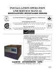
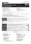
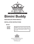
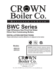
D
E S I G N E D
T O
L
E A D
BWC Series
Instructions for Field Conversion From:
• Natural Gas to LP
• LP to Natural Gas
DANGER
These instructions include a procedure for adjusting the air-fuel mixture on this
boiler. This procedure requires a combustion analyzer to measure the CO2 (or
Oxygen) and Carbon Monoxide (CO) levels in flue gas. Adjusting the air-fuel mixture
without a proper combustion analyzer could result in unreliable boiler operation,
personal injury, or death due to carbon monoxide poisoning.
WARNING
This conversion kit shall be installed by a qualified service agency in accordance
with the manufacturer’s instructions and all applicable codes and requirements
of the authority having jurisdiction. If the information in these instructions is not
followed exactly, a fire, an explosion or production of carbon monoxide may result
causing property damage, personal injury, or loss of life. The qualified service
agency is responsible for proper installation of this kit. The installation is not
proper and complete until the operation of the converted appliance is checked as
specified in the manufacturer’s instructions supplied with the kit.
IMPORTANT
Not all BWC Series boilers may be used on both natural and LP gas. Before
attempting a field conversion, refer to Table 1 to verify that the planned conversion is
permitted.
In addition to these instructions, this kit consists of the following items:
Part Number
980236
980246
980237
980247
Description
Natural to LP Conversion Label Sheet ( 1 of 2)
Natural to LP Conversion Label Sheet ( 2 of 2)
LP to Natural Conversion Label Sheet (1 of 2)
LP to Natural Conversion Label Sheet (1 of 2)
Color
Red
Red
Yellow
Yellow
1) Make sure that the planned fuel conversion is listed in Table 1. If the planned conversion is not shown in Table 1, it is not
permitted. Some of the models shown below may be equipped with either a Dungs or Honeywell gas valve. Refer to Figures
1 and 2 to identify the valve used on the model being converted.
Table 1: Permitted Conversions
Planned
Installation Altitude
Dungs GB-WND 055 (HO)
Dungs GB-WND 055 (HO)
Dungs GB-WND 055 (HO)
Dungs GB-WND 055 (HO)
Dungs GB-WND 055 (HO)
Fuel Converted
From
To
Natural Gas
LP
LP
Natural Gas
Natural Gas
LP
LP
Natural Gas
Natural Gas
LP
BWC120EL
Dungs GB-WND 055 (HO)
LP
Natural Gas
0-10200ft
BWC150EN*
Dungs GB-WND 055 (RH)*
Natural Gas
LP
0-7800ft
BWC150EL
Dungs GB-WND 055 (RH)
LP
Natural Gas
0-10200ft
BWC151EN
Dungs GB-WND 055 (HO)
Natural Gas
LP
0-7800ft
BWC151EL
Dungs GB-WND 055 (HO)
LP
Natural Gas
0-10200ft
BWC225EN**
Honeywell VK8115
Natural Gas
LP
0-7800ft
BWC225EL
BWC300EN
BWC300EL
BWC399EN
BWC399EL
BWC425EN
BWC425EL
Honeywell VK8115
Dungs GB-WND 057
Dungs GB-WND 057
Dungs GB-WND 057
Dungs GB-WND 057
Dungs GB-WND 057
Dungs GB-WND 057
LP
Natural Gas
LP
Natural Gas
LP
Natural Gas
LP
Natural Gas
LP
Natural Gas
LP
Natural Gas
LP
Natural Gas
0-10200ft
0-10200ft
0-10200ft
0-10200ft
0-10200ft
0-10200ft
0-10200ft
Boiler Model
Gas Valve
BWC070EN
BWC070EL
BWC090EN
BWC090EL
BWC120EN
0-10200ft
0-10200ft
0-10200ft
0-10200ft
0-7800ft
* Conversion of BWC150 EN boilers equipped with Honeywell gas valves to LP is not permitted.
** Do not attempt to convert BWC225EN to LP at altitudes above 2000 ft unless the manufacturing date on the rating plate is
after 6/1/10.
2) Conversion of BWC series boilers from one fuel to another is accomplished using the throttle screw on the gas valve. Figure 1 shows the location of the throttle screw on the Dungs GB-WND 055 valve. Figure 2 shows the location of the throttle
screw on the Honeywell valve. Figure 3 shows the location of the throttle screw on the Dungs GB-WND 057 valve. Locate
the throttle on the boiler being converted.
3) If conversion is being made on a new installation, install the boiler in accordance with the installation instructions supplied with the boiler. If an installed boiler is being converted, connect the new gas supply to the boiler, check for gas leaks,
and purge the gas line up to the boiler in accordance with the National Fuel Gas Code (ANS Z223.1) or the requirements of
the authority having jurisdiction.
4) Before attempting to start the boiler, make the number of turns to the throttle screw called for in the Table 2 below.
• When converting from Natural to LP gas, the screw is turned clockwise.
• When converting from LP to Natural Gas, the screw is turned counter-clockwise.
1
Figure 1a: Dungs “HO” Gas Valve Detail (BWC070, BWC090, BWC120, BWC151)
Figure 1b: Dungs “RH” Gas Valve Detail
(BWC150)
Figure 2: Honeywell VK8115
Gas Valve Detail (BWC225)
2
Figure 3: Dungs GB-WND 057 Gas Valve Detail
(BWC300, BWC399, BWC425)
WARNING
The pressure regulator has been factory set using precision instruments and must never
be adjusted in the field. The gas valve outlet pressure is the same for both natural gas and
propane. Make sure that all adjustments are made with the throttle , not the pressure
regulator. Attempting to adjust the pressure regulator will result in damage to the gas valve
and may cause property damage, personal injury or loss of life.
WARNING
The throttle adjustments shown in Table 2 are approximate. The final throttle setting must be
found using a combustion analyzer. Leaving the boiler in operation with a CO level in excess
of the value shown in Table 3 could result in injury or death from carbon monoxide poisoning.
Table 2: Number of Throttle Turns
Full Turns at Various Altitudes
Boiler Model Gas Valve
0-2000ft
2000-5200ft
5200-7800ft
7800ft-10200ft
BWC070
BWC090
BWC120
BWC150
Dungs GB-WND 055 (HO)
Dungs GB-WND 055 (HO)
Dungs GB-WND 055 (HO)
Dungs GB-WND 055 (RH)
2 3/4
2 3/4
4
4 1/4
2 3/4
2 3/4
4 1/2
5
2 3/4
2 3/4
4 1/2
5
BWC151
Dungs GB-WND 055 (HO)
4
4
4
BWC225
Honeywell VK8115
3 1/2
3 1/2
3 1/2
3 1/2
BWC300
Dungs GB-WND 057
2 1/2
2 1/2
2 1/2
2 1/2
BWC399
Dungs GB-WND 057
2 1/2
2 1/2
2 1/2
2 1/2
BWC425
Dungs GB-WND 057
2 1/2
2 1/2
2 1/2
2 1/2
3
2 3/4
2 3/4
IMPORTANT
If the throttle is very far out of adjustment on the “rich” (counter-clockwise) side, the
rules for adjusting the CO2 will reverse: CO2 will actually drop as the throttle is turned
counterclockwise and increase as the throttle is turned clockwise. Under these conditions,
the O2 level will read 0% and the CO level will be extremely high (well over 1000PPM). If
the boiler appears to be operating under these conditions, turn the throttle clockwise. If this
is the problem, the CO2 level will rise as the throttle is turned clockwise, eventually peaking
at between 11% and 13% before falling. Once the CO2 peaks, the CO level should start to
fall. After this happens, continue turning the throttle clockwise until the CO2 drops (or O2
increases) to the level shown in Table 3.
5) Attempt to start the boiler using the lighting instructions located inside the lower front cover of the boiler. If the boiler
does not light on the first try for ignition, allow to boiler to make at least four more attempts to light. If boiler still does not
light, turn the throttle counter clockwise in 1/4 turn increments, allowing the boiler to make at least three tries for ignition at
each setting, until the boiler lights.
6) After the burner lights, force the burner to high fire by simultaneously pressing and holding the “Mode” button and “+“
button. After a few seconds, the display should flash “H”, indicating that the boiler has been driven to high fire. Allow the
boiler to operate for approximately 5 minutes before taking combustion readings. Note: after 15 minutes, the boiler is automatically released from high fire hold. Be sure to restore high fire hold if additional time is needed to obtain high fire combustion readings.
7) Perform a combustion test. Boilers equipped with a concentric vent system have a flue gas sample tap located in the boiler
vent collar (under the screw cap). For other vent systems, the sample probe may be inserted into the terminal. If this is not
possible, remove the flue temperature sensor and insert the analyzer probe in the sensor opening. For the boiler to operate,
this sensor will need to be remain connected to the wiring. If the flue gas sensor is removed, be sure to replace it after
combustion testing is complete.
8) While the burner is at high fire adjust the throttle as needed to obtain the CO2 (or O2) settings shown in the Table 3:
• To reduce the CO2 (increase the O2) turn the throttle clockwise
• To increase the CO2 (reduce the O2) turn the throttle counter-clockwise
Make adjustments in increments of 1/8 to 1/4 turn and allow the boiler at least a minute to respond to each adjustment before
making another. In general, the CO level will be at its lowest somewhere in the CO2 range shown in this table.
Table 3a: Recommended Combustion Settings, Natural Gas
Altitude
Boiler Model
0-2000ft
5200-7800ft
7800ft-10200ft
BWC070
BWC090
BWC120
BWC150
CO2
(%)
9.4
9.5
9.5
8.7
O2
(%)
4.4
4.3
4.3
5.6
Max CO
PPM
75
75
75
75
CO2
(%)
9.4
9.5
9.5
8.7
O2
(%)
4.4
4.3
4.3
5.6
Max CO
PPM
75
75
75
75
CO2
(%)
9.0
9.1
8.8
8.7
O2
(%)
5.1
4.9
5.4
5.6
Max CO
PPM
75
100
100
100
BWC151
9.5
4.3
75
9.5
4.3
75
9.0
5.1
100
BWC225
9.0
5.1
75
9.0
5.1
100
8.8
5.4
100
BWC300
9.0
5.1
75
9.0
5.1
75
8.8
5.4
100
BWC399
9.0
5.1
75
9.0
5.1
75
8.8
5.4
100
BWC425
9.0
5.1
75
9.0
5.1
75
8.8
5.4
100
4
Table 3b: Recommended Combustion Settings, LP Gas
Altitude
Boiler Model
0-2000ft
5200-7800ft
7800ft-10200ft
BWC070
BWC090
BWC120
CO2
(%)
10.4
10.5
10.5
O2
(%)
5.1
5.0
5.0
Max CO
PPM
75
75
75
CO2
(%)
10.4
10.5
10.5
O2
(%)
5.1
5.0
5.0
Max CO
PPM
75
100
100
CO2
(%)
10.2
10.3
O2
(%)
5.4
5.3
Max CO
PPM
100
100
BWC150
10.1
5.6
75
10.1
5.6
100
BWC151
10.5
5.0
75
10.5
5.0
100
BWC225
10.2
5.4
75
10.2
5.4
100
BWC300
10.2
5.4
75
9.9
5.8
100
9.9
5.8
100
BWC399
10.2
5.4
75
9.9
5.8
100
9.9
5.8
100
BWC425
10.2
5.4
75
9.9
5.8
100
9.9
5.8
100
Note: The CO2 and O2 values shown in Table 3 are at high fire and are +/-0.1%.
9) Verify that the gas inlet pressure is between the upper and lower limits shown in Table 4 with all gas appliances (including the
converted boiler) both on and off:
Table 4: Inlet Pressure Limits
Fuel
Natural Gas
LP
Inlet Pressure (inches w.c.)
Min.
5.0
11.0
Max.
14.0
13.0
10) Two sheets of labels are provided with this kit: one for conversions from natural to LP gas and one for conversions from LP to
natural gas. Select the appropriate sheet of labels and apply them as follows:
• Apply the “Rating Plate Label” adjacent to the rating plate.
• Apply the “Gas Valve Label” to a conspicuous area on the gas valve.
• Apply the “Boiler Conversion Label” to a conspicuous surface on, or adjacent to, the outer boiler jacket. Fill in the date of the
conversion and the name and address of the company making the conversion with a permanent marker.
11) Refer to the “Start-up and Checkout” section of the boiler installation manual and perform any checks not already completed.
5
Manufacturer of Hydronic Heating Products
P.O. Box 14818 3633 I. Street
Philadelphia, PA 19134
www.crownboiler.com
PN: 980235
BWC - 01/12 Rev2