1
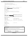
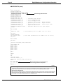
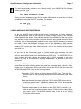
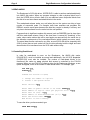
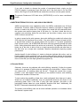
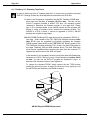
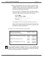
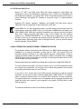
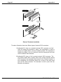
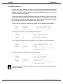
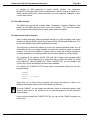
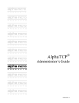
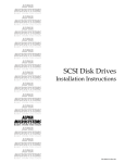
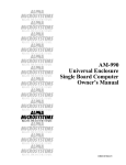
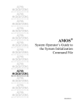
RIGHT. FROM THE START RIGHT. FROM THE START RIGHT. FROM THE START RIGHT. FROM THE START RIGHT. FROM THE START RIGHT. FROM THE START RIGHT. FROM THE START Eagle/Roadrunner Configuration Information RIGHT. FROM THE START RIGHT. FROM THE START RIGHT. FROM THE START RIGHT. FROM THE START RIGHT. FROM THE START RIGHT. FROM THE START RIGHT. FROM THE START PDI-03500-50 Rev. B00 1995 Alpha Microsystems REVISIONS INCORPORATED REVISION A00 A01 B00 DATE July 1995 August 1995 December 1995 Eagle/Roadrunner Configuration Information To re-order this document, request part number PDI-03500-50. The information contained in this manual is believed to be accurate and reliable. However, no responsibility for the accuracy, completeness or use of this information is assumed by Alpha Microsystems. This document was written and illustrated by Jack Chardi and Dan Twaddell. This document may contain references to products covered under U.S. Patent Number 4,530,048. The following are registered trademarks of Alpha Microsystems, Santa Ana, CA 92799: AMIGOS AlphaBASIC AlphaLAN AlphaNET CASELODE AMOS AlphaCALC AlphaLEDGER AlphaPASCAL OmniBASIC Alpha Micro AlphaCOBOL AlphaMAIL AlphaRJE VER-A-TEL AlphaACCOUNTING AlphaFORTRAN 77 AlphaMATE AlphaWRITE VIDEOTRAX The following are trademarks of Alpha Microsystems, Santa Ana, CA 92799: AlphaBASIC PLUS DART inFront/am AlphaVUE ESP AM-PC MULTI AMTEC inSight/am All other copyrights and trademarks are the property of their respective holders. ALPHA MICROSYSTEMS 2722 S. Fairview Street P.O. Box 25059 Santa Ana, CA 92799 Eagle/Roadrunner Configuration Information Page i TABLE OF CONTENTS 1.0 INTRODUCTION . . . . . . . . . . . . . . . . . . . . . . . . . . . . . . . . . . . . . . . . . . . . . . . . 1 2.0 ENTERING THE PIC FOR THE SCSI DISPATCHER . . . . . . . . . . . . . . . . . . . . 1 2.1 Configuring Your AMOS32.INI File . . . . . . . . . . . . . . . . . . . . . . . . . . . . . 2 2.2 READ-AHEAD AND WRITE BUFFERING . . . . . . . . . . . . . . . . . . . . . . . 5 3.0 READ AHEAD . . . . . . . . . . . . . . . . . . . . . . . . . . . . . . . . . . . . . . . . . . . . . . . . . . 6 3.1 Controlling Read-Ahead . . . . . . . . . . . . . . . . . . . . . . . . . . . . . . . . . . . . . 6 4.0 WRITE BUFFERING FOR SCSI-1 AND SCSI-2 DISK DRIVES . . . . . . . . . . . . 7 4.1 Potential Pitfalls . . . . . . . . . . . . . . . . . . . . . . . . . . . . . . . . . . . . . . . . . . . 7 4.2 Setting Up Write Buffering . . . . . . . . . . . . . . . . . . . . . . . . . . . . . . . . . . . 8 5.0 FINAL NOTES . . . . . . . . . . . . . . . . . . . . . . . . . . . . . . . . . . . . . . . . . . . . . . . . . . 9 5.1 Controlling Write Buffering (Caching) . . . . . . . . . . . . . . . . . . . . . . . . . . . 9 APPENDIX A - ROADRUNNER SCSI BUS COMPATIBILITY A.1 ROADRUNNER SCSI TAPE AND HARD DISK DRIVE REQUIREMENTSA-1 A.1.1 Tandberg 1/4" Streaming Tape Drives . . . . . . . . . . . . . . . . . . A-2 A.1.2 AM-645 8mm Magnetic Tape Subsystem . . . . . . . . . . . . . . . . A-4 A.1.3 AM-647 (2GB) DAT Magnetic Tape Subsystems . . . . . . . . . . A-4 A.1.4 AM-648 (2/4GB) DAT Magnetic Tape Subsystems . . . . . . . . . A-4 A.1.5 SCSI Hard Disk Drives . . . . . . . . . . . . . . . . . . . . . . . . . . . . . . A-5 A.2 SCSI TERMINATION USING EXTERNAL TERMINATOR OPTION . . . A-5 A.2.1 Termination Procedure (Without External Terminator) . . . . . . A-7 A.3 TERMINATION POWER . . . . . . . . . . . . . . . . . . . . . . . . . . . . . . . . . . . . A-7 A.3.1 SCSI-2 Bus Termination Power Guidelines . . . . . . . . . . . . . . A-8 A.3.2 SASI Bus Termination Power Guidelines . . . . . . . . . . . . . . . . A-8 APPENDIX B - ROADRUNNER AM-174 PROGRAMMING INFORMATION B.1 ROADRUNNER AM-174 PROGRAMMING INFORMATION . . . . . . . . . B.1.1 The Problem and Why It’s a Problem . . . . . . . . . . . . . . . . . . . B.1.2 What You Must Do... . . . . . . . . . . . . . . . . . . . . . . . . . . . . . . . . B.1.3 One More Caution . . . . . . . . . . . . . . . . . . . . . . . . . . . . . . . . . . B.1.4 New Cache Control Program . . . . . . . . . . . . . . . . . . . . . . . . . B-1 B-1 B-2 B-3 B-3 PDI-03500-50, Rev. B00 Eagle/Roadrunner Configuration Information Page 1 1.0INTRODUCTION Basic instructions on how to use your computer are located in the Eagle Series Computer Owner’s Manual. The Eagle Computer Service Manual contains information on accessing your computer, configuring your computer’s hardware, installing peripherals, etc. This document contains software and peripheral configuration information unique to computers (like your Eagle), which use an AM-172 or AM-174 Roadrunner board. Additionally, this document has been updated to include the "Super Eagle" system. The topics discussed are: 1.Configuring the Roadrunner’s high performance SCSI dispatcher. 2.Enabling the Roadrunner’s write buffering feature. 3.Roadrunner peripheral compatibility information, located in Appendix A. 4.Software considerations when using a 68040 based Roadrunner board, located in Appendix B. 2.0ENTERING THE PIC FOR THE SCSI DISPATCHER One of the software modules that makes your Eagle computer so fast is the SCSI dispatcher. AMOS uses the dispatcher to communicate with the SCSI controller chip. All communications with the SCSI controller chip are handled by the dispatcher. There are two versions of the SCSI dispatcher. SCZRR.SYS is a high-performance, SSD protected version of the SCSI dispatcher, which supports command queueing, synchronous transfers, multi-threaded, and scatter-gather operations. SIMRR.SYS is a simplified version of the SCSI dispatcher, which is not SSD protected and does not support the high performance features supported in SCZRR.SYS. The simple dispatcher (SIMRR.SYS) is also used for making a warm boot tape. When making a warm boot tape for your Eagle computer, you will be prompted to enter the dispatcher name. Simply enter SIMRR.SYS. When you receive your Eagle computer from Alpha Micro, it is configured with the simple SCSI dispatcher (SIMRR.SYS). The first thing you must do when you boot your new Eagle computer is enter the PIC for the high performance SCSI dispatcher (SCZRR.SYS). To obtain the dispatcher PIC code, simply call Alpha Micro at 1-800-289-2574 and let the person on the other end of the phone know what your SSD number is. You will be given a PIC code compatible with your SSD chip. PDI-03500-50, Rev. B00 Page 2 Eagle/Roadrunner Configuration Information Once you enter the product installation code (PIC), the product overlay file is forever modified and will not accept a new PIC. This can be a problem if you happen to enter an incorrect PIC. As a safeguard, make a copy of the dispatcher overlay file before you do the SSD encodement. Type: LOG SYS: RETURN COPY SCZDSP.SAV=SCZDSP.OVR RETURN By saving an unmodified version of the overlay file, you will be able to re-enter the PIC if necessary. To perform the SSD encodement, enter the following commands: SCZPIC RETURN You will be prompted for a Product Installation Code (PIC). This PIC is a unique identifier for your system. Enter the PIC, carefully verifying you have entered it correctly and press RETURN . After a brief pause, you will be returned to AMOS command level and you can proceed with the remainder of the installation. If you see the error message ?Improper SSD after you have rebooted the computer, it probably means you have entered the PIC incorrectly. As mentioned above, you cannot SSD encode the same overlay twice; to re-encode the dispatcher software, do this command first: LOG SYS: RETURN COPY SCZDSP.OVR=SCZDSP.SAV RETURN You will now be able to re-encode the dispatcher. If after once again rebooting the computer you still receive the same error, check with your dealer to make sure the correct PIC was supplied for your computer. Now that you have entered the PIC code for the high performance SCSI dispatcher (SCZRR.SYS), you will need to enable it in your AMOS32.INI file. This procedure is covered in the next section. 2.1Configuring Your AMOS32.INI File On the next two pages, a sample system initialization command file is shown, which is similar to the factory supplied AMOS32.INI file on your Eagle computer. The key Roadrunner related statements in the AMOS32.INI file are shown in bold. At the bottom of each of the example pages, there is additional information for each of the bolded entries. PDI-03500-50, Rev. B00 Eagle/Roadrunner Configuration Information Page 3 :T ; System Type/Users: Eagle 040/1 ; System Drive Type: 540MB SCSI ; Drive Control/Dvr: RR SCSI/SCZRR.DVR ; AMOS Monitor Type: AMOS32 2.2C PR8/95 (PIC) ; JOBS 5 ; JOBALC JOB1 ;JOB2 ;JOBALC SPOOLA,SPOOLB,SPOOLC,SPOOLD ; per parallel ports ; Increased QUEUE block allocation QUEUE 2000 ; LOAD LOAD.LIT LOAD DEL.LIT LOAD SYSMSG.USA LOAD TRMDEF.LIT ; TRMDEF TRM1,AM318=0:19200,ALPHA,350,350,350,EDITOR=15 ;TRMDEF TRM2,AM318=1:19200,ALPHA,100,100,100,EDITOR=15 ; DEL TRMDEF ; VER PARITY Simple dispatcher, for temporary use only! ; SCZDSP SIMRR.SYS ;SCZDSP SCZRR.SYS ; High-Performance dispatcher, requires PIC! LOAD DEVTBL.LIT DEVTBL DSK1,DSK2,DSK3,DSK4,DSK5 DEVTBL TRM,RES,MEM DEVTBL /STR0 ; streaming tape drive ;DEVTBL FLP0 ; 3-1/2" floppy drive ;DEVTBL MIN0 ; 5-1/4" floppy drive ;DEVTBL /EGP0 ; parallel port - Eagle 100/200 ;DEVTBL /EPP0,EPP1 ; parallel ports - Eagle 300-500 ;DEVTBL /SEP0,SEP1,SEP2,SEP3 ; parallel ports - Super Eagle (550) ; DEL DEVTBL ; LOAD BITMAP.LIT BITMAP DSK ; paged bitmap ;BITMAP FLP,180,0 ;BITMAP MIN,100,0 ; DEL BITMAP ; MSGINI 20K ERSATZ ERSATZ.NEW MC1129 Queue Block Allocation Roadrunner based computers (like your Eagle) require a high number of queue blocks. The example above shows the QUEUE block statement set to 2000, which should be sufficient for most Eagle configurations. SCSI Dispatcher Definition statements for both the simple and high performance dispatchers are included in the AMOS32.INI file. Once you have entered the PIC for the high performance dispatcher (SCZRR.SYS), you will want to change your SCSI dispatcher statements from this: SCZDSP SIMRR.SYS ;SCZDSP SCZRR.SYS to this: ;SCZDSP SIMRR.SYS SCZDSP SCZRR.SYS AMOS32.INI File PDI-03500-50, Rev. B00 Page 4 Eagle/Roadrunner Configuration Information AMOS32.INI File (cont.) ; LOAD SYSTEM.LIT SYSTEM SYSMSG.USA SYSTEM DCACHE.SYS/N/M/U 300K ;SYSTEM DVR:DSK/N 100K 60 Write buffering enable statement SYSTEM CMDLIN.SYS SYSTEM SCNWLD.SYS SYSTEM QFLOCK.SYS SYSTEM TRM.DVR[1,6] SYSTEM STR.DVR[1,6] ; streaming tape driver ;SYSTEM FLP.DVR[1,6] ; 3-1/2" floppy driver ;SYSTEM MIN.DVR[1,6] ; 5-1/4" floppy driver ;SYSTEM EGP.DVR[1,6] ; parallel port driver - Eagle 100/200 ;SYSTEM EPP.DVR[1,6] ; parallel port driver - Eagle 300-500 ;SYSTEM SEP.DVR[1,6] ; parallel port driver - Super Eagle (550) ;SYSTEM ACD.DVR[1,6] ; Alpha CD-ROM driver ;SYSTEM DVR:AM319S.LDV/N ; EtherNet LAN driver for Super Eagle SYSTEM ; DEL SYSTEM ; ;SMEM.LIT 300K ; Shared Memory Pool for AMOS 2.2C (or later) ; LOG OPR: SYSTEM SERVICE SET SEEKOP DSKO: ; Disk Seek Optimization for AMOS 2.2C (or later) LOG SYS: ; DET DSKERR SET HEX ; ;SETJOB JOB2,TRM2,300K,JOBSET.INI ; LOAD MOUNT.LIT MOUNT DSK1: MOUNT DSK2: MOUNT DSK3: MOUNT DSK4: MOUNT DSK5: ; DEL * ; CACHE OFF ON LOCK/MFD DSK0: LOCK/UFD DSK0:[1,4] LOCK/FILE VUE.LIT,COPY.LIT,DIR.LIT EXIT ; DO SCZRR.MSG Message instructing you to enter the PIC and enable the high-performance dispatcher ; MEMORY 0 MC1130 Write Buffering Enable To enable the write buffering feature, you simply remove the semicolon at the beginning of the line. However, before you do this, read the section in this document that explains the benefits and risks associated with this feature. SCSI Dispatcher PIC Message When you boot your Eagle computer, a message will be displayed reminding you that the high performance SCSI dispatcher needs to have its PIC code entered. Once you have entered the PIC for the dispatcher, you will propably want to delete the message command (DO SCZRR.MSG) from your AMOS32.INI file. PDI-03500-50, Rev. B00 Eagle/Roadrunner Configuration Information Page 5 To avoid unnecessary problems, never directly modify your AMOS32.INI file. Always create a test file; type: COPY TEST.INI=AMOS32.INI RETURN Once you have created your test file, you make modifications to it and then test those modifications using the MONTST command. For example: LOG OPR: RETURN MONTST AMOS32.MON,TEST.INI RETURN 2.2READ-AHEAD AND WRITE BUFFERING In the past, AMOS systems achieved high levels of performance by using a "Herbie" style disk controller (such as the AM-520) to offload a large portion of the overhead associated with disk access. One additional benefit of this offloading is that extra cycles are available on the Herbie controller to perform functions such as read-ahead and write buffering. Both of these schemes are used by the current AM-520 firmware, but cannot be used on other non-intelligent interfaces such as the Alpha Micro SASI interface because the main processor running AMOS has to handle control of the SASI interface, stealing CPU cycles away from other resources, such as the terminal service system and user jobs. In the case of the Roadrunner board, a "hybrid" Herbie style controller has been implemented. A programmable RISC controller is used for SCSI bus communications and for data transfer to and from the Roadrunner’s SCSI bus. The 68030/040 CPU is only involved with setup before and cleanup after a SCSI command is sent to a device—the rest of the command, including data transfer, is handled by the RISC processor. Having the RISC processor take care of these details, allows us to implement both read-ahead and write buffering without the need for a separate Herbie controller. Also, higher levels of performance will be seen when using a fast SCSI-2 disk drive than with an AM-520 using ESDI drives for the following reasons: Physically, SCSI-2 drives are faster than most ESDI drives. They spin the platters twice as fast (reducing latency) and have significantly faster seek times. Data transfer rates are higher with fast SCSI-2 drives. ESDI drives have a maximum transfer rate of 18Mbits/s, whereas fast SCSI-2 drives transfer data at 80Mbits/s (or around 4 times faster). The data transfer path is much faster with the RISC SCSI-2 controller. It is able to read from or write to system memory 32 bits at a time, taking 150ns per read or write. The AM-520 transfers data 16 bits at a time, taking 210ns per 16 bit transfer. PDI-03500-50, Rev. B00 Page 6 Eagle/Roadrunner Configuration Information 3.0READ AHEAD The Roadrunner’s SCSI disk driver, SCZRR.DVR, is able to perform read-ahead directly into AMOS disk cache. When any program attempts to read a physical block from a disk, the SCZRR driver will also read up to an additional seven sequential blocks from the disk drive and store these read-ahead blocks in the cache. This read-ahead scheme works very well when jobs on the system are doing a large number of sequential reads. For example, data base searches and programs like REDALL execute much faster because the data they require is already in memory and only has to be transferred from the cache into the user partition. Programs that do significant random disk access (such as RNDRED) tend to slow down with this read ahead scheme. Most of the slow down is caused by "thrashing" of the cache, where cache entries that will be used again are removed from the cache due to the allocation requirements of the read-ahead blocks (which typically are never used). The actual data transfer overhead is very little, as most SCSI disk drives (especially fast SCSI-2 drives) have a track cache built into the drive allowing both the target and read ahead blocks to be transferred over the SCSI cable without delay. 3.1Controlling Read-Ahead In order for read-ahead to occur on the Roadrunner, the AMOS disk cache, DCACHE.SYS, must be installed as normal and additionally, the full SCSI dispatcher (SCZRR.SYS) must also be installed. The number of read-ahead blocks to be transferred into cache on every physical disk access is controlled by the FIXLOG program. When you use FIXLOG to create a driver for the Roadrunner hardware, a new option will appear, which is the number of read-ahead blocks. For example, type: LOG DVR: RETURN FIXLOG RETURN FIXLOG.LIT Version x.x(xxx) 1. Change the number of logicals 2. Create a sub-system driver Enter choice: 2 RETURN Enter name of generic driver to be used: SCZRR RETURN Enter number of logical units per physical unit: 10 RETURN Enter SCSI id (0-6): 0 RETURN Enter number of read-ahead blocks (0-7): 5 RETURN Enter new driver name: MAX RETURN New driver is now in memory. To save the driver you have created, type: SAVE MAX.DVR RETURN PDI-03500-50, Rev. B00 Eagle/Roadrunner Configuration Information Page 7 If you wish to disable or change the number of read-ahead blocks, simply use the FIXLOG program to generate a new disk driver and if the disk driver is for the DSK: device, don’t forget to use MONGEN and embed the new driver into the system monitor. The generic Roadrunner SCSI disk driver (SCZRR.DVR) is set for seven read-ahead blocks. 4.0WRITE BUFFERING FOR SCSI-1 AND SCSI-2 DISK DRIVES AMOS (and therefore every application written for AMOS) understands only 512 byte disk blocks. Therefore, when a disk write request is made by a program, a single block transfer is made to the disk drive. If the program then writes the next sequential block, the system must wait the latency time of the drive (i.e., the time it takes the drive to complete one revolution) before the next block can be written. Latency even on fast SCSI-2 drives is around 7ms. In order to speed up the write process, when write buffering is enabled, all writes to the SCSI disk are first transferred into a buffer. If the write buffer becomes at least half full, or around three quarters of a second passes with no reads, or if a preset "guaranteed flush" timeout occurs, the SCZRR.DVR disk driver will begin scanning through the write buffer, finding blocks that need to be written out to the drive. The algorithm used to flush blocks out to the drive is able to find up to eight consecutive blocks and write them to the disk drive as a single write command, therefore dramatically improving system performance. Another benefit of write buffering is it tends to eliminate duplicate disk writes, such as bitmap updates during operations such as copying files and tape restores and prevents head thrashing when reading through random access data files and writing a sequential file out to the disk (as most report generation programs do). 4.1Potential Pitfalls Obviously, there can be problems with write buffering, especially if either the system crashes or is powered off while writes are pending in the write buffer. If either of these two cases occur, all pending writes will be lost. Though this sounds like a major problem, it can also happen if write buffering is not enabled. However, write buffering increases the number of writes at risk. To help reduce the possibility of data loss, certain safeguards have been put in place. Writes are not buffered indefinitely; they are performed whenever the device is not performing reads. Even if the drive is busy with read requests, the buffer is still periodically flushed, based on a user definable "absolute flush time." Additionally, the MONTST command automatically flushes the write buffer. The primary write buffering risks are an errant software operation or a hardware failure that causes a system crash. PDI-03500-50, Rev. B00 Page 8 Eagle/Roadrunner Configuration Information Therefore, you must weigh the potential for data loss (which is always there) versus the dramatic performance increase seen when using write buffering. If you are worried about the reliability of write buffering, it may be worth keeping in mind that the AM-520 disk controller has always used write buffering on a track-by-track basis (not quite as efficiently as the Roadrunner write buffering scheme however). The SMARTDRV programs used since MS-DOS 5.0 do write buffering (you may have noticed the "Waiting for system shutdown" message when re-booting a PC with CTRL-ALT-DELETE) and Unix based computers have always done it! 4.2Setting Up Write Buffering In order to enable write buffering, you must be using the full SCSI dispatcher (SCZRR.SYS). Write buffering is enabled by adding parameters to the SYSTEM statement used to load the driver. All hard disk subsystem drivers for the Roadrunner SCSI interface must be loaded into system memory. Appending "/N" followed by the buffer-size and flush-period will enable write buffering for that device. For example: SYSTEM DVR:devn/N buffer-size flush-period where devn is the device you want to enable write buffering for (for example DSK and SUB). One SYSTEM command is required for each different SCSI disk driver present in the system. For example, if you had two 1.2GB SCSI-2 drives named as DSK0-36 and DSK37-73 and one 540MB SCSI-2 drive named SUB0-17, you would need one additional SYSTEM command for the DSK device (although it’s really two physical drives) and one additional SYSTEM command for the SUB device. When specifying write buffering for a device, two files are automatically loaded into system memory: .DVR and .WRC, which are the driver and cache buffer. This is true for all SCSI disk devices except the DSK device. For the DSK device, the file DSK.DVR does not need to be created because it is already loaded into the system monitor. Therefore, for the DSK device, only the file DSK.WRC will be loaded into system memory. The buffer-size is the size of the write buffer (you specify the size in Kilobytes). Specifying a buffer size of over 100KB is unlikely to improve performance. The flush-period is the absolute maximum number of seconds data may be left in the write buffer without being written to the disk. For example, if you specified 30, you would know that after 30 seconds any pending writes would be written to the disk. This is true even if the disk is constantly busy servicing reads. In the three drive example mentioned earlier, the added SYSTEM commands would look similiar to this: SYSTEM DVR:DSK/N 100K 60 SYSTEM DVR:SUB/N 100K 60 ;Driver in AMOS will create DSK.WRC ;Load SUB.DVR and create SUB.WRC PDI-03500-50, Rev. B00 Eagle/Roadrunner Configuration Information Page 9 This would set up 100KB of write buffering for the DSK devices and 100KB of write buffering for the SUB device. All three drives would have their write buffers flushed every minute (or sooner if the drives are not busy with read requests). 5.0FINAL NOTES Both read-ahead and write buffering schemes used on the Roadrunner hardware dramatically improve system performance in our lab tests. Both schemes are fine tuned for both the 68030/040 processor and RISC SCSI controller and do not take cycles away from AMOS like other commercially available disk optimization software. Although our lab tests attempt to simulate the "real world" of user applications, they probably use the resources of the Roadrunner CPU and SCSI sub-system completely differently than your application does, therefore we highly recommend you experiment with both cache and write buffer sizes, read-ahead blocks and flush periods on an installed system to find the best possible combination for that system. 5.1Controlling Write Buffering (Caching) Since the release of UPS Monitor Software version 1.3(174), the user can control the turning on and off of the write buffering feature. Earlier Eagle systems must use the serial UPS software to control write buffering, while the AM-4000 and Super Eagle systems can use either the UPS switch contact port and/or the serial UPS software. The UPS monitor setup is selected from menu option "W" for Write Cache Control, and the user can then select either option "A" or "B". The serial UPS software is designed to work with the Toshiba UPS products sold by Alpha Microsystems. PDI-03500-50, Rev. B00 APPENDIX A ROADRUNNER SCSI BUS COMPATIBILITY All peripherals shipped as part of a factory integrated Eagle computer are Roadrunner compatible. However, you should be aware of the following information: 1.Your bootable hard disk drive and any secondary hard disk drives (if applicable) are fully configured for Roadrunner operation. 2.Older AM-626 Tandberg streaming tape drives are shipped with SCSI-2 firmware installed, and in some cases, you may also receive the SCSI-1 firmware, which will be packaged separately. If you ever need to use the AM-626 drive in a configuration that does not support SCSI-2, you can install the older firmware. Also, if you did not receive the old firmware, it can be ordered from Alpha Micro under part number PDB-00626-91. 3.AM-627, AM-628 and newer AM-626 Tandberg streaming tape drives are shipped configured for SCSI-2 operation. These drives use a flash ROM for their firmware which can be software downloaded for SCSI-1 or SCSI-2 operation. Refer to the setup instructions appearing later in this appendix. 4.AM-647 (2GB) and AM-648 (2/4GB) DAT tape drives are factory configured for SCSI-2 operation. They can easily converted back to SCSI-1 operation using the instructions that appear later in this document. A.1ROADRUNNER SCSI TAPE AND HARD DISK DRIVE REQUIREMENTS Roadrunner has an on-board high performance SCSI interface incorporated into its design. To insure a successful installation, you should carefully read the next few sections dealing with SCSI peripherals and Roadrunner compatibility. The Roadrunner’s on-board high performance SCSI interface supports both SCSI-1 and SCSI-2 hard disk and magnetic tape devices. However, because of the potential increase in performance, we highly recommend the use of SCSI peripherals that support SCSI-2. PDI-03500-50, Rev. B00 Page A-2 Appendix A A.1.1Tandberg 1/4" Streaming Tape Drives In order to warm boot from a Tandberg tape drive, it must be set to a higher numerical SCSI ID (1 through 6) than any other tape device connected to the SCSI bus. 1.In order to be Roadrunner compatible, the AM-625 Tandberg 150MB tape drive must have firmware at revision -06:00 or later. You can use the SCSI.LIT program (included in AMOS 2.2C and 1.4C operating system releases) to determine the firmware revision of your tape drive. Simply type in the command SCSI at the AMOS prompt and the program will display a string of numbers which includes the firmware revision. The AM-625 is a SCSI-1 device; it cannot be upgraded to SCSI-2. AM-625 backups are not able to span tapes. 2.AM-626 525MB Tandberg SCSI tape drives can be upgraded to SCSI-2 in two ways. Older models of the TDC 3800 with firmware revisions earlier than -07:01 must be upgraded by physically upgrading the firmware PROM located inside the drive (p/n PDB-00626-90). Newer models of the TDC 3800 with firmware revisions -07:01 or later, use flash ROM similar to the larger Tandberg 1GB and 2GB streamer drives. The flash ROM type drives can be upgraded without removing the drive from the computer. To upgrade the newer model of the 3800 see step 3. If the firmware is not upgraded, the drive can still be used with Roadrunner hardware as a SCSI-1 device, but only if it has firmware at revision -04:08 or later. You can use the SCSI.LIT program as explained in step 1 to determine the firmware revision of your tape drive. To replace the firmware PROM, simply remove the two TORX screws holding the drive’s top cover in place; lift off the top cover; gently pry out the old PROM; and install the new PROM as shown: TORX SCREWS Make sure the notch in the chip (indicating pin-1) points toward the rear of the drive. FIRMWARE PROM LOCATION MAC860 AM-626 Physical PROM Replacement PDI-03500-50, Rev. B00 Roadrunner SCSI Bus Compatibility Page A-3 3.AM-627 1GB, AM-628 2GB, and newer models of the AM-626 525MB Tandberg SCSI tape drives also require a firmware update to be SCSI-2 compatible. However, these drives use a flash ROM for their firmware which can be updated without removing the drive from the computer. To update the drive’s firmware proceed as follows: Once the computer has completed booting use the SCSI command to determine the drive’s current firmware version, then enter the following commands to update the tape drive firmware for SCSI-2 operation: LOG OPR: RETURN FWUPD DVR:xxxxxx.FW RETURN Loading Firmware ........ Enter Target Device (ie. STR0:): STR0: RETURN Sending firmware to drive .......... where xxxxxx is the name of the firmware update file you want to load. After the firmware has been downloaded, allow at least 30 seconds for the streamer drive to update its firmware, then reboot your computer to reset and initialize the new tape drive parameters. The following is a list of firmware update files currently available: Tape Drive Current Firmware (as reported by the SCSI command) Operation Filename Tandberg TDC 4xx0 firmware 05:07 or earlier SCSI-2 SCSI-1 TSCZ2.FW TSCZ1.FW Tandberg TDC 4xx0 firmware 07:05 SCSI-2 SCSI-1 S20705.FW S10705.FW Tandberg TDC 3800 firmware 07:01 or later SCSI-2 SCSI-1 38S275.FW 38S171.FW Once the firmware has been updated, the drive is only compatible with AM-4000/4000M’s, AM-3000M’s with AM-540’s, Eagle’s, and all Roadrunner enhanced computers. If the drive is ever used in a configuration with an earlier style CPU board, the firmware must be converted back to SCSI-1 operation. PDI-03500-50, Rev. B00 Page A-4 Appendix A A.1.2AM-645 8mm Magnetic Tape Subsystem In order for the Exabyte tape drive to work with the Roadrunner hardware, new firmware must be installed in the drive. The updated firmware is available from Alpha Micro under part number PDB-00645-90. Once the new firmware is installed, the Exabyte tape drive will operate in SCSI-1 mode only. The ability to span tapes is not supported on the Exabyte tape drive. A.1.3AM-647 (2GB) DAT Magnetic Tape Subsystems The AM-647 DAT tape drive is SCSI-2 ready and does not require any firmware updates to be compatible with Roadrunner hardware. However, on the back of the DAT drive a change may need to be made to one of the configuration switches. Switch S4 must be placed in the "ON" position in order for the drive to operate in SCSI-2 mode. After making the configuration switch change, you must turn the drive off and then power the drive back on in order for the switch change to take affect. A.1.4AM-648 (2/4GB) DAT Magnetic Tape Subsystems The AM-648 DAT tape drive is SCSI-2 ready and does not require any firmware updates to be compatible with Roadrunner hardware. However, on the back of the DAT drive a change may need to be made to one of the configuration jumper blocks. When looking at the tape drive from the rear, the SCSI-1/SCSI-2 jumper is located in the far upper left corner, next to the drive I.D. jumpers. This jumper block must be removed for SCSI-2 operation, or installed for SCSI-1 operation. The normal Eagle/Roadrunner operating mode is SCSI-2. After making the configuration jumper change, you must turn the drive off and then power the drive back on in order for the configuration change to take affect. Additionally, the AM-648 DAT drive can operate in two data modes: standard or compressed data. When operating in the standard mode the drive capacity is approximately 2 gigabytes. When operating in the compressed mode the capacity is approximately doubled, or 4 gigabytes. The AMOS command called TMODE allows you to switch between compressed and non-compressed tape writing modes. Tapes written in standard (non-compressed) mode can also be read by AM-647 Archive Python DAT drives. PDI-03500-50, Rev. B00 Roadrunner SCSI Bus Compatibility Page A-5 A.1.5SCSI Hard Disk Drives Maxtor LXT, MXT, and 7000 series SCSI disk drives supplied by Alpha Micro are supported for use on the Roadrunner’s SCSI port. Also, in order to be compatible with the Roadrunner hardware, your Maxtor MXT SCSI-2 compatible disk drive must have a sticker indicating it has special 6F+ firmware or it must be using 1.5 or later production firmware. Quantum LPS, Empire, Lightning, Trailblazer, and Fireball SCSI disk drives sold by Alpha Micro are also supported on the Roadrunner’s SCSI port. Under AMOS 2.2 (or later) operating systems, you can divide your hard disk drive into logical devices larger than 32MB. In fact, you could take a 540MB drive and make it one giant 540MB logical. While this is perfectly acceptable, you may get a memory allocation error when running programs that load a copy of the bitmap into your memory partition—e.g., DSKANA and MONTST. To use these types of programs, you will need at least one job on your computer with enough memory allocated to allow you to load the large bitmap. Depending on the size of the logical device, you may need a memory partition between 100 and 800KB. A.2SCSI TERMINATION USING EXTERNAL TERMINATOR OPTION The preferred method of terminating the SCSI bus in an AMOS based computer is the installation of an external terminator. In Early April of 1993, the external SCSI bus terminator became standard on all AMOS based computer configurations. Using an external terminator makes the task of installing an add-on subsystem (like a portable CD-ROM drive) easier, eliminating the necessity of removing terminators from a SCSI device located in the host computer. External terminators are available from Alpha Micro under part number PRA-00222-00. To use the external terminator, you need to insure none of your SCSI peripherals inside the computer are terminated. You will also need to follow the guidelines in the section on providing termination power for the SCSI bus. If you have a 10 or 21-slot rack mount VME computer and want to install an external terminator, you will need to order a special adapter cable, DWB-10200-01. The adapter cable is required, because there is no external SCSI connector on these computers. The special cable has a connector that is compatible with the external terminator and would also allow easy access to your computer for a portable CD-ROM drive or other SCSI subsystem. The external terminator is shown in the following illustration: PDI-03500-50, Rev. B00 Page A-6 Appendix A BAIL LOCKS CONFIGURATION A SI SC (PRA-00222-00) EXTERNAL SCSI BUS TERMINATOR CONFIGURATION B SI SC MAC821 #4 SCREW AND WASHER External Terminator Installation The above illustration shows two different types of external SCSI connectors: 1.Configuration"A" shows an extended external SCSI connector and bail locks for holding the terminator in place. This configuration is used on almost all of Alpha Micro’s currently available product. The terminator is installed by sliding it over the connector and then latching the bail locks into the notches in the terminator. 2.Configuration"B" shows a flush mounted external SCSI connector. The only product Alpha Micro currently offers using a flush mounted external SCSI connector is the pedestal (also known as the "Classic") chassis. In this configuration, the terminator inserts into a cutout in the sheet metal and over the SCSI connector. The terminator is held in place with two #4screws and washers. PDI-03500-50, Rev. B00 Roadrunner SCSI Bus Compatibility Page A-7 A.2.1Termination Procedure (Without External Terminator) 1.All AMOS based computers (with or without Roadrunner upgrades) with one SCSI hard disk drive must have that hard disk drive installed with its terminators installed. 2.All AMOS based computers (with or without Roadrunner upgrades) with more than one SCSI device must insure that only the last SCSI device, the device attached to the connector located farthest down the cable away from the CPU, board has its terminators installed. Any other SCSI devices must have their terminators removed. 3.All AMOS based computers (with or without Roadrunner upgrades) which have a SCSI magnetic tape drive as their only SCSI device must have the tape drive configured with its terminators installed. 4.For subsystem installations used in AMOS based applications, the last SCSI device attached to the connector located farthest down the cable away from the host computer must have its terminators installed. A.3TERMINATION POWER In order to properly control SCSI bus termination, a termination power source must be provided; this is especially important when using an external terminator. Why is Termination Power so important when using an external terminator? In order for terminators to do their job, they must have a power source. In most (but not all) cases, a SCSI peripheral will supply termination power to its own on-board terminators, even if the SCSI host controller or no other SCSI peripheral is supplying termination power to the SCSI bus. However, for an external terminator to be effective there has to be termination power supplied to the SCSI bus. If no termination power is available, the external terminator is not going to do its job, which means your SCSI bus is not terminated. This may result in a computer that either won’t boot or once booted may tend to hang frequently. Because SCSI-2 devices transfer data at a higher rate, they are more prone to display problems when improperly terminated. The termination power source can be configured in one of two ways, depending on your application: AMOS based computers with SCSI-2 implementation (i.e., AM-4000 computers, AM-540 enhanced AM-3000M computers, all Roadrunner enhanced computers, etc) should be configured to supply termination power via the host controller. When termination power is supplied by the host controller, it is not necessary to have one of your internally mounted SCSI peripherals configured to supply termination power to the SCSI bus. PDI-03500-50, Rev. B00 Page A-8 Appendix A AMOS computers using the 50-pin SASI bus, which includes non-SCSI-2 enhanced AM-1000, AM-1200, AM-1400, AM-1600, AM-2000, AM-2000M, AM-3000, and AM-3000M computers, require that one of the internally mounted peripherals be configured to supply termination power to the SCSI bus. A.3.1SCSI-2 Bus Termination Power Guidelines Use these guidelines for supplying termination power to AM-4000 computers, Roadrunner enhanced computers, AM-540 enhanced AM-3000M computers, etc: 1.AMOS based computers with SCSI-2 implementation will be configured with the host controller supplying termination power to the SCSI bus. 2.When the SCSI host controller is supplying termination power, you want your internally mounted SCSI peripherals to be configured so they do not supply termination power. 3.If a computer with one or more SCSI peripherals is cabled to a subsystem with additional SCSI devices, the SCSI devices in the subsystem should be configured so they do not supply termination power. Ideally, you want the SCSI host controller in the main system to be the sole source of termination power. The termination power guidelines described above are valid even when you are using SCSI peripherals that do not support SCSI-2 protocol. The SCSI host controller on AM-190 and AM-540 boards is permanently configured to supply termination power to the SCSI bus. On Roadrunner boards, the termination power feature can be enabled or disabled by setting a jumper. As of 07/26/94, Alpha Micro began configuring all Roadrunner boards with termination power enabled. See the Roadrunner installation instructions for information on how to configure the termination power jumper. A.3.2SASI Bus Termination Power Guidelines Use the following guidelines to determine which peripheral will be used to supply termination power for the 50-pin SASI bus: 1.Whenever possible, only one SCSI peripheral will be configured to supply termination power to the SASI bus. 2.If a computer has more than one SCSI peripheral and at least one of those peripherals is a disk drive, one disk drive will be configured to supply termination power to the bus. The other disk or tape SCSI devices will be configured so they do not supply termination power. PDI-03500-50, Rev. B00 Roadrunner SCSI Bus Compatibility Page A-9 3.If a computer does not have a SCSI disk drive, but does have one or more SCSI magnetic tape or CD-ROM drives, then one of these devices will be configured to supply termination power. 4.If a computer with one or more SCSI peripherals is cabled to a subsystem with additional SCSI devices, one SCSI device in the host computer would normally be configured to supply termination power for the bus. You should avoid having a SCSI device in both the host computer and the subsystem configured to supply termination power. Ideally, you want the source of the termination power for the bus to be supplied by one power source only! For information on how to configure terminator power on SCSI hard disk and magnetic tape peripherals, see the following documents: Each SCSI disk drive shipped by Alpha Micro has a one page notice with jumper configuration information, including instructions on how to configure termination power. AM-62X SCSI 1/4" Streaming Tape Drive Installation Instructions, PDI-00625-00, revision A07 or later. AM-647 DAT Tape Drive Installation Instructions, PDI-00647-00, revision A04 or later. AM-648 DAT Tape Drive Installation Instructions, PDI-00648-00, revision A00 or later. PDI-03500-50, Rev. B00 APPENDIX B ROADRUNNER AM-174 PROGRAMMING INFORMATION B.1ROADRUNNER AM-174 PROGRAMMING INFORMATION The MC68040 processor used on the AM-174 Roadrunner board contains more internal instruction cache (4096 bytes) than earlier MC68030-based processors. Increased internal cache is one of the features which contributes to the improved performance of the Roadrunner 040 board; however, if your software does not properly manage this instruction cache, it could be adversely affected. When the instruction cache is enabled—as it would be during normal system operation—any memory location which is executed by the processor is loaded into the instruction cache. This improves performance for those cases where the same location is executed again, since the instruction will be read from cache instead of slower main memory. B.1.1The Problem and Why It’s a Problem The problem arises when that same memory location, which has now been loaded into cache, is modified. Because data operations—such as the MOV instruction—do not update the instruction cache, when your program next executes the memory location, it may read the old contents, which are still in the instruction cache, rather than pulling the instruction from main memory where it was updated. This is known as self-modifying code. In this context, self modifying code is any code which is written to memory as data, such as when read from disk to memory, and then executed as instructions. AMOS handles the most common cases, such as reading data from disk or during the FETCH monitor call, but cannot handle cases in your software where you are handling program overlays or building instructions on the fly. Such code is often present in "trick" code like that used to perform SSD-based software protection, although it may be present anywhere. This issue was present on 68030 based systems, but the limited cache size on that processor made it a much smaller problem. Tricks to flush the cache that worked on the 68030, such as forcing a context switch, will probably not work reliably on the 68040. PDI-03500-50, Rev. B00 Page B-2 Appendix B B.1.2What You Must Do... The only sure way to address this issue is to flush the instruction cache after loading instructions into memory, but before executing those instructions. Because the method by which you flush the cache is different on the various 680x0 processors, you will need to add code specific to the 68040. You must be certain to handle the different processors individually. Failure to do so may result in inadvertently disabling certain processor features. For example, trying to flush the 68040 cache using the 68030 method will result in the 68040’s instruction cache being disabled. This will seriously degrade system performance. To test to see if a program is executing on a 68040, use the following code fragment: MOV AND BNE SYSTEM,D7 #SY$M40,D7 WE$ARE$ON$040 ; get the system flags ; is the 040 bit set? ; yes - take the branch To simply flush the cache, use the following code fragment: SUPVR CINVA LSTS #0 ; enter supervisor mode ; invalidate cache ; return to user mode To turn off the instruction cache, as is needed in some cases, use the following code: SUPVR SVLOK CLR MOVEC LSTS D7 D7,CACR #0 ; ; ; ; ; ; enter supervisor mode ensure interrupts are off clear the CACR flags return to user mode and enable interrupts again To turn the instruction cache back on, use the following: SUPVR SVLOK CINVA MOV MOVEC LSTS #^H08000,D7 D7,CACR #0 ; ; ; ; ; ; ; enter supervisor mode turn off interrupts invalidate cache set the ICACHE enable bit return to user mode and enable interrupts again Remember to turn the instruction cache back on! If you don’t, system performance will be seriously impaired. PDI-03500-50, Rev. B00 Roadrunner AM-174 Programming Information Page B-3 In versions of M68 appearing in earlier AMOS releases, the instructions MOVECD7,CACR and CINVA were not implemented. With the release of AMOS 2.2C, which includes M682.0(181), these instructions are now supported. Examples of their use are shown above. B.1.3One More Caution The 68040 also has internal registers called Transparent Translation Registers (also present on the 68030) that you must be sure not to modify. This is far less common than instruction cache issues, but will cause system failure if modified. B.1.4New Cache Control Program Some existing third party software packages making use of self modifying code, which worked fine with the 68030, will no longer work with the 68040 based Roadrunner. This is due to the 68040’s large (4096 byte) instruction cache. The ideal way to handle this problem is to have the software developer either not use self modifying code, or to properly disable and enable the instruction cache as required. However, you may find yourself in a position where a third party software developer is no longer available, or is unwilling to make the necessary changes in a timely fashion. As a solution to this problem, AMOS 2.2C and 1.4C include a new program called COMPAT.LIT. This program works in conjunction with an ASCII file, which you create using AlphaVUE, called COMPAT.DAT. Within COMPAT.DAT, you list programs that can only be run with the 68040’s instruction cache disabled. For example, the COMPAT.DAT file shown below would disable caching for the three programs listed: SCHDLP INIJOB ;This is a comment FAXUIT Since there are no Alpha Micro programs that require the instruction cache to be disabled, the program names used in the example are fictitious. By using COMPAT, you can disable the instruction cache for selected programs, while allowing other users on the system to run non-selected programs with the instruction cache enabled. Once you have created your COMPAT.DAT file, you can run the COMPAT program one of two ways: PDI-03500-50, Rev. B00 Page B-4 Appendix B From the AMOS prompt, you can type: COMPAT COMPAT.DAT RETURN or you can add this same command into your system initialization command file. If you simply enter the command: COMPAT RETURN you will get a display showing the list of programs that have been selected for the special cache control. Also, you will get some statistical information in the form of the total number of CPU context switches which are non-cached, and the percentage of the non-cached context switches that each of the selected programs caused. A display like the one shown below, which has a very high percentage of non-cached CPU context switches, would indicate that system performance is hindered, because very little use of the instruction cache it taking place. The following programs run with internal cache disabled: STIC FAXUIT (active in 88.7% of total context switches, 99.6% of non-cached) (active in 0.2% of total context switches, 0.3% of non-cached) A total of 89.0% of context switches were non-cached If you are having problems getting a certain software package to run on your Roadrunner, try adding the program to the list of programs in the COMPAT.DAT file. You may find the program will run with the instruction cache disabled. PDI-03500-50, Rev. B00