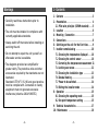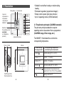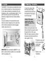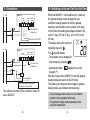
1
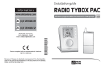
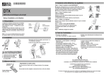
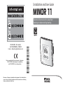
Installation and User Guide
MINOR 11
DELTA DORE - Bonnemain
35270 COMBOURG - FRANCE
E-mail : [email protected]
Device compliant with the requirements of directives:
2004/108/CEE (Electromagnetic compatibility)
and 2006/95/CEE (Low voltage safety)
Because of changes in standards and equipment, the characteristics
given in the text and the illustrations in this document are not binding
unless confirmed by Delta Dore.
*2702007_rev.1*
Electronic thermostat for underfloor
heating or radiant ceiling heating
Warnings
1- Contents
• Carefully read these instructions prior to
installation.
• The unit must be installed in compliance with
currently applicable standards.
• Always switch off the mains before installing or
servicing the unit.
• Do not attempt to repair the unit yourself; an
after-sales service is available.
• The diagrams provided are simplified for
greater clarity. The protective units and other
accessories required by the standards are not
illustrated.
Standard UTE NF C15-100 and good practice
must be complied with. Connected or nearby
equipment must not generate excessive
interference (directive 2004/108/EEC).
-2-
1 - Contents . . . . . . . . . . . . . . . . . . . . . . . . . . 3
2 - Presentation . . . . . . . . . . . . . . . . . . . . . . . 4
2.1 Pilot wire principle (GIFAM standard) . . . 5
3 - Location . . . . . . . . . . . . . . . . . . . . . . . . . . 6
4 - Mounting / Connection . . . . . . . . . . . . . . . . 7
5 - Connections . . . . . . . . . . . . . . . . . . . . . . . . 8
6 - Switching on the unit for the first time . . . . 9
7 - Installer commissioning . . . . . . . . . . . . . . 10
7.1 Choosing the temperature displayed . . . 10
7.2 Choosing the control sensor . . . . . . . . . 10
7.3 Correcting the temperature measurement 11
7.4 Locking user access . . . . . . . . . . . . . . . 12
7.5 Choosing the installation type . . . . . . . 13
7.6 Gradual heating . . . . . . . . . . . . . . . . . . 13
7.7 Power to be switched . . . . . . . . . . . . . . 14
7.8 Exiting the installer mode . . . . . . . . . . 14
8 - Operation . . . . . . . . . . . . . . . . . . . . . . . . 15
8.1 Choosing the operating mode . . . . . . . . 15
8.2 Set-point temperature setting . . . . . . . 15
9 - Technical characteristics . . . . . . . . . . . . . . 17
10 - Maintenance . . . . . . . . . . . . . . . . . . . . . 18
-3-
2- Presentation
Relay status
Current mode
Set-point
temperature or
temperature
measured per
MINOR 11
Heating
demand
mode
Auto
Off
Comfort
Selection of
the operating mode
or configuration
(installer)
Economy
Frost
Protection
Adjustment buttons
15 mm 33 mm
• Suitable for underfloor heating or radiant ceiling
heating
• Permanent regulation (proportional integral)
• Simple control system (pilot wire principle)
• Up to 6 operating modes (GIFAM standard)
2.1 The pilot wire principale (CALYBOX standard)
The pilot wire principle enables the required
operating mode to be selected from a programmer
(CALYBOX range, Driver range, etc.).
The MINOR 11 thermostat thus controls the
corresponding temperature.
80 mm
80 mm
Order sent by
the programmer
Part fitting into the
flush-mounted box
-4-
Corresponding temperature
controlled by the thermostat
Comfort
Comfort setting (5°C to +30°C)
Comfort- 1°C
Comfort - 1°C setting
Comfort- 2°C
Comfort - 2°C setting
Economy
Economy setting (5°C to +30°C)
Frost Protection
Frost protection Frost protection can
be set from 5°C to 15°C (7°C by default)
Off
Heating switched off
-5-
3- Location
4- Mounting / Connection
The MINOR 11 thermostat is mounted flush-mounted in a flush-mounted box. It should be placed in
a room whose temperature represents the mean
temperature, with a recommended height of 1.5 m
and it should be away from any heat sources
(fireworks, sunlight) and from air flows (window,
door, etc.).
To avoid unwanted air movements that would
distort the sensor measurement, the wire entry
into the flush-mounted box must be plugged
(mastic, glass wool, etc.).
Approx.
height
1.50 m
To open the casing, slide
the moving tabs using a
screwdriver and remove the
front panel from the base to
be flush mounted.
Switch off the power
supply to the system
before carrying out any
operation
Moving
tabs
MODE
Before securing the base to the
flush-mounted box, pass the wires
through the hole in the base.
When the base is secured, connect
the wires to the terminal (strip the
wires: approx. 6 mm).
Fit back the cover and
lock it by pushing the
moving tabs
downward.
Min. 40 cm
IMPORTANT: Do not install the MINOR 11 on a
wall in contact with the outside or in an unheated
room (e.g. garage, etc.).
-6-
"Click"
Switch on the
installation.
-7-
5- Connections
L
6- Switching on the unit for the first time
MINOR 11
Load
L
10A - 230V
Pilot Underfloor
N Wire sensor
6 7
Pilot wire from
programmer
Maximum load 2.300 W
Max. power: 2,300 W, otherwise relay
L
MINOR 11
Load
L
10A - 230V
N
Pilot Underfloor
Wire sensor
6 7
Pilot wire from
programmer
load
The relay capacity depends on
the power to be switched
The reference number of the underfloor sensor to
use is 6300037.
-8-
When the MINOR 11 is first switched on, it starts up
the “gradual heating” mode designed for new
underfloor heating systems for which a gradual
heating is recommended (over a period of 20 days).
In this mode, the heating percentage is limited to 8%
on the 1st day, 12% the 2nd day... up to 100% on the
20th day.
The display shown the number of
remaining days and
.
The
symbol flashes.
- The program can be stopped at
any moment by pressing
.
- pressing the button
displays the current
program P1.
After the 20-day period, MINOR 11 exits the gradual
heating mode and returns to the Off mode.
The heating can always be started again in gradual
heating mode. (see Installer commissioning).
- The percentage shown above is calculated in
relation to the regulation time base,
- The gradual heating mode depends on the
set-point temperature.
-9-
7- Installer commissioning
To enter this mode, press the button
for 10 seconds until CF01 is
displayed.
7.1 Choosing the temperature displayed (CF01)
: Temperature of the room measured by
MINOR 11
: Current set-point temperature (default mode)
Select by pressing the or buttons
and
,
confirm by pressing and releasing
. Go on to
the next menu.
7.2 Choosing the control sensor (CF02)
: Sensor within the casing (by
default)
7.3 Correcting the temperature measurement
(CF05)
If you notice a difference between the temperature
recorded (thermometer) and the temperature
measured by the unit, this menus allows you to
correct the difference (+/-5°C in increments of 0.1°C).
E.g. The temperature displayed is 19°C and the
temperature recorded is 20°C, so set
+1°C.
Make the selection by
or
,
Confirm by pressing and
releasing
.
Go on to the next menu.
You must wait at least 24 hours until the effect of
the correction can be observed in the room.
: Underfloor sensor (optional)
Select by pressing the or buttons
and
, confirm by pressing and releasing
.
Passage au menu suivant.
- 10 -
- 11 -
7.4 Locking user access (CF06)
7.5 Choosing the installation type (CF07)
Important: Before activating the user locking feature,
select the required operating mode (
).
This menu is used to determine the type of
installation so that the most suitable regulation
settings are used.
: Les touches sont verrouillées.
Only the set-point configured before
the locking operation can be changed
to +/- 3°C (except for the
and
modes).
: Active buttons (default display).
Make the selection by the buttons
Confirm by pressing and releasing
Go on to the next menu.
or
.
: Underfloor heating application - P.I. type
regulation (default display)
: Ceiling heating application - P.I. type regulation
Paramètre disponible si choix sonde interne §7.2
,
Select by pressing the buttons
confirm by pressing and releasing
Go on to the next menu.
or
, and
.
7.6 Gradual heating (CF09)
CF09 is displayed.
: Start-up program 1 (dry floor).
: Start-up program disabled
Select by pressing the buttons
confirm by pressing and releasing
- 12 -
- 13 -
or
, and
.
7.7 Power to be switched (CF10)
This parameter is only displayed if the
Underfloor heating mode (CF07 - § 7.5)
and the internal sensor (CF02 - § 7.2)
are selected.
: Up to 1,000 W (direct control)
: From 1,000 W to 2,300 W (direct control, by
default)
: Greater than 2,300 W (contact switch control)
Press the button several times for rapid access to
a specific menu
8- Operation
8.1 Choosing the operating mode
Select the operating mode by pressing and
releasing the button repeatedly
:
MINOR 11 follows the mode
requested by the programmer.
MINOR 11 regulates according to
Comfort
the Comfort set-point configured.
MINOR 11 regulates according to
Economy
the Economy set-point configured.
MINOR 11 regulates according to the
Frost
Protection Frost protection set-point configured.
AUTO
OFF
The heating is shut down
8.2 Set-point temperature setting
7.8 Exiting the installer mode
You can exit the installer mode by
pressing the button
after the
last menu (CF09 - § 7.6 or CF10
- § 7.7) or automatically after
2 minutes without pressing any
button.
- 14 -
8.2.1 Set-point setting for the sensor within the
casing (selection of sensor type made §7.2)
Select the mode to set (
the button
.
,
or
) by using
Use
or
, to make your choice (5°C to
+30°C or 5°C to 15°C for the
).
In Comfort mode, MINOR 11 will regulate
according to the set-point configured.
- 15 -
When a choice is made to display the current
temperature (default mode, § 7.1), the first time the
button
or
is pressed will display room
temperature, pressing it a second time allows you
to adjust the set-point.
8.2.2 Underfloor sensor set-point setting
(selection of sensor type made in § 7.2)
Select the mode to set (
by the button
.
or
, Frost protection)
Use
or
, to make your choice (setting of
5 to 40°C for Comfort or Economy, and 5 to 30°C for
Frost protection).
Note: Note: Setting the floor temperature to 26°C
corresponds to a room temperature of about 20°C.
A floor temperature of 23°C corresponds to a room
temperature of about 18°C.
The values specified are theoretical values.
The settings must be readjusted after a few days
use.
- 16 -
10- Technical characteristics
Electrical
• 230 V, 50 Hz power supply, ±10%
• Class II insulation
• Power consumption: 0.5 VA
• Power supplied operating contact output, 10 A,
230 V
• Automatic action: type 1.C
• 1 pilot wire input from programmer
Specific operation
• 6 Operating modes:
- Comfort and economy (adjustable from 5°C to
30°C)
- Comfort -1°C and Comfort -2°C
- Frost protection adjustable from 5°C to 15°C
(except for underfloor sensor applications)
- Off
• P.I. type regulation (proportional integral),
20 minute time base either in relation to the
thermostat sensor, or in relation to an underfloor
sensor.
• eu.bac certificate no. 020713
Application: Electric Underfloor Heating
CA: 0.7
- 17 -
Mechanical
• Dimensions: LxHxD = 80 x 80 x 48 mm
• IP 30
• Wall-mounted on flush-mounted box
• Installation in an environment with normal pollution
levels
Technical
• Storage temperature: -10°C to +70°C
• Operating temperature: 0°C to +40°C.
11- Maintenance
Problem
Diagnosis / Solutions
Nothing appears on the
screen
No power supply
Check the power supply
The indication
flashes
• The “gradual heating”
mode is enabled
See chapter 7
You cannot set a
set-point temperature
The buttons are locked
See the “installer mode”
chapter or
AUTO mode is enabled
(set-points cannot be changed)
- 18 -