1
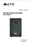
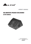
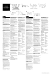
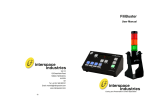
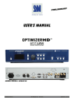
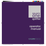
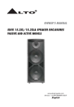
OWNER'S MANUAL
MS8/MS8A/MS12S/MS12SA
SPEAKER ENCLOSURE
PASSIVE/ACTIVE MODELS
www.altoproaudio.com
Version 1.1 Apr 2009
English
IMPORTANT SAFETY INSTRUCTION
CAUTION
RISK OF ELECTRIC SHOCK
DO NOT OPEN
TO REDUCE THE RISK OF ELECTRIC SHOCK
PLEASE DO NOT REMOVE THE COVER OR
THE BACK PANEL OF THIS EQUIPMENT.
THERE ARE NO PARTS NEEDED BY USER
INSIDE THE EQUIPMENT. FOR SERVICE,
PLEASE CONTACT QUALIFIED SERVICE
CENTERS.
WARNING
To reduce the risk of electric shock
and fire, do not expose this equipment
to moisture or rain.
Dispose of this product should
not be placed in municipal waste
and should be separate collection.
11. Move this Equipment only with a cart,
stand, tripod, or bracket,
This symbol, wherever used, alerts you to the
specified by the
presence of un-insulated and dangerous voltages
manufacturer, or
within the product enclosure. These are voltages that
sold with the
may be sufficient to constitute the risk of electric
Equipment. When
shock or death.
a cart is used, use
This symbol, wherever used, alerts you to
caution when
important operating and maintenance instructions.
moving the cart /
Please read.
equipment
Protective Ground Terminal
combination to
AC mains (Alternating Current)
avoid possible
Hazardous Live Terminal
injury from tip-over.
ON: Denotes the product is turned on.
12. Permanent hearing loss may be caused by
OFF: Denotes the product is turned off.
exposure to \ extremely high noise levels.
CAUTION
The US. Government's Occupational Safety
Describes precautions that should be observed to
and Health Administration (OSHA) has
prevent damage to the product.
specified the permissible exposure to noise
1. Read this Manual carefully before operation.
level.
2. Keep this Manual in a safe place.
These are shown in the following chart:
3. Be aware of all warnings reported
with this symbol.
HOURS X DAY SPL EXAMPLE
4. Keep this Equipment away from water and
90 Small gig
8
moisture.
92 train
6
5. Clean it only with dry cloth. Do not use
95 Subway train
4
solvent or other chemicals.
97 High level desktop monitors
3
6. Do not damp or cover any cooling opening.
100 Classic music concert
2
Install the equipment only in accordance with
the Manufacturer's instructions.
102
1,5
105
1
7. Power Cords are designed for your safety. Do
110
0,5
not remove Ground connections! If the plug
does not fit your AC outlet, seek advice from
0,25 or less 115 Rock concert
a qualified electrician. Protect the power
According to OSHA, an exposure to high SPL in
cord and plug from any physical stress to
excess of these limits may result in the loss of
avoid risk of electric shock. Do not place
heat. To avoid the potential damage of heat, it is
heavy objects on the power cord. This could
cause electric shock or fire.
recommended that Personnel exposed to
equipment capable of generating high SPL use
8. Unplug this equipment when unused for long
hearing protection while such equipment is
periods of time or during a storm.
under operation.
9. Refer all service to qualified service personnel
The apparatus shall be connected to a mains
only. Do not perform any servicing other than
those instructions contained within the
socket outlet with a protective earthing
User's Manual.
connection.
10. To prevent fire and damage to the product,
use only the recommended fuse type as
indicated in this manual. Do not short-circuit
the fuse holder. Before replacing the fuse,
make sure that the product is OFF and
disconnected from the AC outlet.
The mains plug or an appliance coupler is used
as the disconnect device, the disconnect device
shall remain readily operable.
IN THIS MANUAL:
1. INTRODUCTION
1
2. SPEAKER CABINET QUICK START
2
3. HOOKUP DIAGRAMS
4
4. WIRE CONNECTIONS
6
5. RIGGING
7
6. FREQUENCY RESPONSE
9
7. PANEL DESCRIPTION-MS8A/MS12SA
11
8. PANEL DESCRIPTION-MS8/MS12S
13
9. TECHNICAL SPECIFICATION
14
10. WARRANTY
16
1. INTRODUCTION
Thank you very much for expressing your confidence in LTO products by purchasing MS8/MS8A/MS12S/MS12SA speaker system. The MS series cabinets
are specifically designed for using in hi-quality performance site and the precise
sound reinforcement commercial place. uses trapezium configuration which
greatly decreases the resonance of the standing wave in the cabinet. These
cabinets uses hi-density matrix spray-paint technics and the bottom bracket
design which make mounting quickly and Flexibly. The HF compression driver and
vented LF for fully professional performance.
The MS8A/MS12SA speaker cabinets include some exclusive innovations such as
switch mode power supply and digital power circuitry (in selected modes) that
make them the lightest powered cabinets of this kind ever made.
The MS full range models include another Alto innovation: The MODELLER.
Thanks to this circuitry, User can select 16 different tastes and applications.
The 16 kinds of sound presets especially thought for application with or without
subwoofer, for voice optimised application, for Disco Music, for jazz, for Rock &
Roll among others.
Enjoy your MS8/MS8A/MS12S/MS12SA speaker cabinet and make sure to read
this manual carefully before operation.
1
SP
OT
L
IG
2. SPEAKER CABINET QUICK START
HT
Make all initial connections with all the equipment powered off, and ensure that
all the main volume controls are turned completely down.
1). Connect one side of the speaker cable to the output CHA/CHB or Binding
Post of your stereo power amplifier and the other side to the input socket
of your speaker cabinet.
2). Complete other connections as illustrated.
3). Turn on your mixer first, then the stereo power amplifier.
4). Turn up the volume controls of your amplifier to about 70%.
5). Use PFL function to get the proper input level for the mixer, and adjust
the main mix level control to manipulate the output level.
6). After using, turn off your stereo power amplifier first, then the mixer.
Speaker Cable
Speaker Cable
MS8
MS8
Stereo
D1
SIG CLIP PROT
18
16
20
6
500W
SIG CLIP PROT
18
22
24
26
12
CH1
28
30 (dB)
16
20
2
22
24
26
12
6
CH2
28
30 (dB)
Power Amplifier
Tripod
Mount
Right
Left
Main Mix
Output
Main Mix
Output
Mixer
2
Tripod
Mount
SP
OT
L
IG
2. SPEAKER CABINET QUICK START
HT
Make all initial connections with all the equipment powered off, and ensure
that all the main volume controls are turned completely down.
1). Connect one side of the signal cable at your audio mixer into output
left /right (with Stereo-Jack or XLR) and the other side of the cable into
the line input (Stereo-Jack) of your active speaker cabinet.
2). Connect the power cord to mains.
3). Turn on your mixer first, then the active speaker cabinets.
4). Turn up the volume control of the active speaker cabinets.
5). Use PFL function to get the proper input level for the mixer, and adjust
the main mix level control to manipulate the output level.
6). After using, turn off your active speaker cabinets first, then the mixer.
Signal Cable
Signal Cable
MS8A
MS8A
Power Cord
Power Cord
Left
Tripod
Mount
Right
Main Mix
Main Mix
Tripod
Mount
Output
Output
Mixer
3
HOOK
3.HOOKUP DIAGRAMS
UP
Two active speaker in stereo operation
LINE IN
MAIN OUT L
MAIN OUT R
LINE IN
MS8A
MS8A
MIXER
Tripod
Mount
Tripod
Mount
Multiple active speakers with the same stereo source
MIXER
MAIN OUT LEFT
MAIN OUT RIGHT
LINE IN
LINK
LINK
LINK TO NEXT SPEAKER
LINE IN
MS8A
Tripod
Mount
4
LINK TO NEXT SPEAKER
LINE IN
MS8A
Tripod
Mount
Tripod
Mount
Tripod
Mount
HOOK
3.HOOKUP DIAGRAMS
UP
Two active subwoofers and two active satellite speakers
LINE IN
LINE IN
MS8A
MS8A
Tripod
Mount
Tripod
Mount
MAIN OUT LEFT
MAIN OUT RIGHT
LINE IN LEFT/MONO
LINE IN LEFT/MONO
MS12SA
MS12SA
MIXER
One active subwoofers and two active satellite speakers
LINE IN
LINE IN
MS8A
MS8A
MS12SA
Tripod
Mount
LINE IN LEFT/MONO
MAIN OUT LEFT
LINE IN RIGHT
Tripod
Mount
MAIN OUT RIGHT
5
MIXER
4. WIRE CONNECTIONS
-.For Active Speaker Cabinets
As to these circumstances,audio connections is mostly intended for the signal
flow,so,determine the wire configuration according to your real application
system and its connecting facility.Normally,you have the following choices:
-.For Passive Speaker Cabinets
Please only use the power connectors to make connections with other signal source
equipment for the passive speaker cabinets. The power connector has four terminals:
1+, 1-, 2+, 2-.
1-
2-
1+
2+
In our cabinets, only 1+/1- are used to connect the Speaker+/Speaker-, and 2+/2are not used.
6
5. RIGGING
The MS8/MS8A speaker cabinet also provides the bracket for fixed installation,
How to use them?
1).Inventory
Before beginning installation, inventory kit to items listed.
Item
I
II
III
Q'ty
1PCS
2PCS
2PCS
Description
MH-8B Bracket / Wallmount
Screw, M10*30*1.5PH, Black ( in the cabinet)
Washer, Neoprene, 1.5t
35mm
Warning:
Installation should only be done by an experienced technician. Improper
installation may cause serious injury . The surface where the bracket/cabinet
is to be fastened must have enough structural integrity .
2).Mounting the Bracket
Due to various construction methods and materials used today, the hardware
for securing the bracket to the mounting surface is not supplied. It is recommended that you consult a building professional for the proper mounting
hardware before mounting the bracket.
3).Removing the Shipping Hardware, Remove the flat head screws from the top
and the bottom of the cabinet using a 5mm wrench.
7
5. RIGGING
4).Choosing which slot to use there are three slots in each bracket arm. use
the forward slot (as shown)when the cabinet is facing perpendicular to the
bracket mounting surface.
5).Hanging the Cabinet
A. Place a neoprene gasket on the bracket's lower arm. Center it on the
appropriate slot.
B. Position the cabinet between the bracket arms.
C. Align the bracket's top slot to the cabinet's M10 threaded hole.
D. Holding the cabinet in position, insert the screw through the bracket slot
and into the cabinet's top threaded hole and hand tighten.
E. Repeat step D through the bottom bracket hole.
F. Position cabinet and tighten both screws with a 5mm wrench.
8
6. FREQUENCY RESPONSE
MS8A
+110
+100
d
B
S
P
L
+90
+80
+70
+60
30
50
100
200
500
1k
2k
5k
10k 20k
Hz
MS8
+110
+100
d
B
S
P
L
+90
+80
+70
+60
20
50
100
200
500
1k
Hz
2k
5k
10k 20k
9
6. FREQUENCY RESPONSE
MS12SA
+110
+100
d
B
S
P
L
+90
+80
+70
+60
20
50
100
200
500
1k
2k
5k
10k 20k
1k
2k
5k
10k 20k
Hz
MS12S
+110
+100
d
B
+90
S
P
L
+80
+70
+60
20
50
100
200
500
Hz
10
SP
OT
L
IG
7. PANEL DESCRIPTION-MS8A
HT
ACTIVE FULL RANGE: MS8A
(1) BI-POLAR MAIN POWER SWITCH
(2) AC POWER SOCKET WITH MAIN FUSE
(3) GROUND SWITCH
(4) CLIP INDICATOR RED LED
(5) LINK OUT ON XLR CONNECTOR
(6) LINE INPUT ON COMBO CONNECTOR
(7) MAIN VOLUME CONTROL
(8) POWER SWITCHUNG BUTTOM
(9) PRESETS SELECTOR
Via this knob, you can select the right effect you wish to perform. There
are total 16 options for you, JAZZ CLUB+SUB, VIRTICAL SUB, STAGE
MONITOR, JAZZ CLUB, CONCERT HALL+SUB, DISCO, VOCAL, ROCK &
ROLL, FLAT, DRUM KICK, ANTIRUMBLE, CONCERT HALL, ARENA+SUB,
LOUDNESS, ROCK & ROLL+SUB and ACOUSTIC.
(6) (5) (4) (7) (9)
8
9
10
7
11
12
6
5
0dB
13
4
INPUT
LINK
BAL
14
15
3
MAX
VOLUME
8
-
SIGNAL
LIMIT
2
1
16
PRESETS
POWER
1.FLAT
2.DRUM KICK
3.ANTIRUMBLE
4.CONCERT HALL
5.ARENA+SUB
6.LOUDNESS
7.ROCK & ROLL+SUB
8.ACOUSTIC
9.JAZZ CLUB+SUB
10.VIRTUAL SUB
11.STAGE MONITOR
12.JAZZ CLUB
13.CONCERT HALL+SUB
14.DISCO
15.VOCAL
16.ROCK & ROLL
(3)
MS8A
MODEL
SERIAL
DESIGNED IN ITALY
AC INPUT
110-120V~50/60Hz
220-240V~50/60Hz
AC FUSE
100-120V: T6.3AL
220-240V: T3.15AL
POWER CONSUMPTION:350W
100 -120V
AC
INPUT
220 -240V
ON
OFF
Use only with a 250V fuse
(2) (8) (1)
11
SP
OT
L
IG
7. PANEL DESCRIPTION-MS12SA
HT
ACTIVE SUBWOOFERS: MS12SA
(9) (10) (11) (12)
(13)
(6)
110 -120V
(7)
0dB
-
RIGHT
IN
SIGNAL
LIMIT
(8)
MAX
VOLUME
8
LEFT / MONO
GND
220 -240V
ON
LEFT / MONO
OFF
RIGHT
OUT
AC INPUT
PHASE
110-120V~50/60Hz
220-240V~50/60Hz
LEFT
RIGHT
NORMAL
BY PASS
REVERSE
HPF 80Hz
POWER
Use only with a 250V fuse
AC FUSE
110-120V: T6.3AL
220-240V: T3.15AL
POWER CONSUMPTION: 350W
LINK
AC INPUT
POWER
MS12SA
MODEL
SERIAL
DESIGNED IN ITALY
ON-OFF main power switch
Input AC power socket with main fuse
(3)
POWER, Green LED, indicate ON status
(4)
BYPASS Switch Select the Hiqh pass filter or by pass
(5)
Ground Lift Switch
(6)
LINE IN RIGHT.ON XLR CONNECTOR
(7)
LINE IN LEFT/MONO ON COMBO CONNECTOR
(8)
LINK LEFT/RIGHT ON XLR CONNECTOR
(9)
SIGNAL/LIMIT, Red LED, indicate ON status
(10) VOLUME main power amplifier control
(11) PHASE Switch Reverse the Polarity of the subwoofer output
(12) OUT LEFT/RIGHT ON 2xXLR CONNECTOR
(13) POWER SWITCHUNG BUTTOM
12
(3)
(4)
(5)
SP
OT
L
IG
8. PANEL DESCRIPTION-MS8/MS12S
HT
CONNECTION PLATE
PASSIVE FULL RANGE: MS8
(1) INPUT
Receive the power coming from an external power amplifier.
(SPK +1/-1 connected; +2/-2 not connected)
(2) THRU
Direct LINK for connect in parallel a second speaker cabinet.
(SPK +1/-1 connected; +2/-2 not connected)
Besides, the passive crossover included the electronic protection
on the driver.
MS12S
MS8
SOUND REINFORCEMENT SPEAKER SYSTEM
SOUND REINFORCEMENT SPEAKER SYSTEM
POWER HANDLING:
CONTINUOUS - 150 Watts
PEAK - 300 Watts
IMPEDANCE:
8 Ohm
POWER HANDLING:
CONTINUOUS: 300 Watts
IMPEDANCE: 4 Ohm
Max SPL: 120dB at 1mt
MODEL
MODEL
SERIAL
SERIAL
DESIGNED AND DEVELOPMENT IN ITALY
INPUT
THRU
DESIGNED AND DEVELOPMENT IN ITALY
INPUT
OUTPUT
LINK
(1)
(2)
(a)
(b)
PASSIVE SUBWOOFERS: MS12S
a). INPUT: Receive the signal coming from an external amplifier.
(SPK +1/-1 connected;+2/-2 not connected).
b). OUTPUT: Power output for satellite speaker, under passive crossover
filtered at 125Hz (SPK +1/-1 connected; +2/-2 not connected).
13
SP
OT
L
IG
9. TECHNICAL SPECIFICATION
HT
MS8A
Active System Type
Power System
Frequency Response
Maximum SPL @ 1m
Coverage (HxV)
Transducer Low
Transducer High
Active Crossover
Input Connector
Input Sensitivity
External Control
Power Supply
Enclosure Construction
Mounting / Suspension
Dimensions (HxWxD)
Net Weight
Shipping Weight
MS8
Passive System Type
Power System
Frequency Response (-10dB)
Sensitivity (1w @ 1mt)
Impedance:
Maximum SPL @ 1m
Coverage (HxV)
Transducer Low
Transducer High
Passive Crossover
Input Connectors
Enclosure Construction
Mounting / Suspension
Dimensions (HxWxD)
Net Weight
Shipping weight
14
8" 2-way Active Modelling Loudspeaker
2-way Bi-Amp, with MODELLER
350W-LOW CLASS D/65W-HIGH CLASS AB in EIAJ
200W-LOW CLASS D/35W-HI CLASS AB in Continuous
MODELLER presets setting
120dB Continuous/123dB Peak (Calculated)
70 x 70 nominal
8" Woofer, 1.5"voice coil, with double ventilation
1" Neodymium on Spherical Horn (Tractrix contour)
2KHz under analog processor
LINE-COMBO/ LINK-XLR-F Balanced (15kohm)
Line +0dB
MODELLER with 16 Preset / Volume Control/ Power ON with
Green LED/ Clip Limiter with Red LED/ Ground Lift.
120-240 Volt, in Switching Power mode.
MDF wood cabinet, glued and reinforced, black painted, one metal
handle and rubber foot.
Two point for suspension, one metal pole-mount, optional bracket.
493 x 304 x 293 mm (19.41" x 11.97 x 11.54")
12.06kg / 26.53 lbs
14.56kg / 32.03 lbs
8" 2-way Passive Speaker Cabinet
2-way Passive
150W continuous / 300W peak
67Hz-18kHz
94.5dB SPL
8 (nominal)
116dB continuous/119dB peak (Calculated)
70 x 70 nominal
8" Woofer, 1.5"voice coil, with double ventilation
1" Neodymium on Spherical Horn (Tractrix contour)
2.25kHz at 12dB/oct, with HF protection
Two Parallel SPK NL-4 for INPUT/ THRU
MDF wood cabinet, glued and reinforced, black painted;
one metal handle and rubber foot.
Two point for suspension , one standard pole-mount plus a
optional bracket.
493 x 304 x 293 mm (19.41" x 11.97 x 11.54")
11.29kg / 24.84 lbs
13.79 kg / 30.34 lbs
SP
OT
L
IG
9. TECHNICAL SPECIFICATION
HT
MS12SA
12" Active Subwoofer Speaker Cabinets
Power System
350W Class D in EIAJ/300W Class D in Continuous
Frequency Response (-10dB)
47Hz-125Hz
Maximum SPL @ 1m
121dB Continuous/124dB Peak (Calculated)
Transducer Low
12" Woofer, 2.5"voice coil, with double ventilation
Active Crossover
HPF 80Hz under analog processor
Input Connector
L-R Input (Combo/ XLR-F) / L-R Link (2-XLR-M) /
L-R Output (2-XLR-M) Balanced (15kohm)
Input Level
L-R Input Line 0dBu
External Control
Volume Control/ Phase Switch / HPF-80Hz By-Pass/ Power
ON with Green LED/ Clip Limiter with Red LED/ Ground Lift.
Power Supply
120-240 Volt, in Switching Power mode.
Enclosure Construction
15mm Plywood cabinet, glued and reinforced, resistant
black paint, metal grille, rubber foot.
Mounting
One metal standard pole-mount plus one metal handle
Dimensions (HxWxD)
370x 530 x 480 mm (14.57" x 20.87 x 18.90")
Net Weight
18.6kg / 41.01 lbs
Shipping Weight
20.8kg / 45.86 lbs
MS12S
12"Passive Subwoofer Speaker Cabinet
Power System
300W continuous
Frequency Response (-10dB)
47Hz-160Hz
Sensitivity (1w @ 1mt)
96dB SPL
Impedance:
4
Maximum SPL @ 1m
120dB continuous/123dB peak (Calculated)
Transducer Low
12" Woofer, 2.5"voice coil, with double ventilation
Passive Crossover
125Hz at 6dB/oct
Enclosure Construction
15mm Plywood cabinet, glued and reinforced, resistant
Input Connectors
INPUT-SPK NL-4 / OUTPUT-SPK NL-4, for Satellite Speaker
Mounting
One metal standard pole-mount plus one metal handle
(nominal)
black paint, metal grille, rubber foot.
Dimensions (HxWxD)
370x 530 x 480 mm (14.57" x 20.87 x 18.90")
Net Weight
18.10 kg / 39.90 lbs
Shipping weight
20.30 kg / 44.8 lbs
15
10.WARRANTY
1. WARRANTY REGISTRATION CARD
To obtain Warranty Service, the buyer should first fill out and return the enclosed Warranty Registration Card within 10 days of the Purchase Date.All the
information presented in this Warranty Registration Card gives the manufacturer a better understanding of the sales status, so as to purport a more
effective and efficient after-sales warranty service.Please fill out all the information carefully and genuinely, miswriting or absence of this card will void your
warranty service.
2. RETURN NOTICE
2.1 I n case of return for any warranty service, please make sure that the product is well packed in its original shipping carton, and it can protect your
unit from any other extra damage.
2.2 Please provide a copy of your sales receipt or other proof of purchase with
the returned machine, and give detail
2.3 A brief description of the defect will be appreciated.
2.4 Please prepay all the costs involved in the return shipping, handling and
insurance.
3. TERMS AND CONDITIONS
3.1
LTO warrants that this product will be free from any defects in materials and/or workmanship for a period of 1 year from the purchase date if
you have completed the Warranty Registration Card in time.
3.2 The warranty service is only available to the original consumer, who purchased this product directly from the retail dealer, and it can not be transferred.
3.3 During the warranty service, LTO may repair or replace this product at
its own option at no charge to you for parts or for labor in accordance with
the right side of this limited warranty.
3.4 This warranty does not apply to the damages to this product that
occurred as the following conditions:
Instead of operating in accordance with the user's manual thoroughly, any
abuse or misuse of this product.
Normal tear and wear.
The product has been altered or modified in any way.
Damage which may have been caused either directly or indirectly by another
3.5 In no event shall LTO be liable for any incidental or consequentialdamages.
Some states do not allow the exclu-sion or limitation of incidental or consequential damages, so the above exclusion or limitation may not apply to you.
3.6 This warranty gives you the specific rights, and these rights are
compatible with the state laws, you may also
have other statutory rights that may vary from state to state.
16
SEIKAKU TECHNICAL GROUP LIMITED
NO. 1, Lane 17, Sec. 2, Han Shi West Road, Taichung 40151, Taiwan
www.altoproaudio.com Tel: 886-4-22313737
email: [email protected] Fax: 886-4-22346757
All rights reserved to ALTO. All features and content might be changed
without prior notice. Any photocopy, translation, or reproduction of part of this
manual without written permission is forbidden. Copyright c 2009 Seikaku Group
NF03258-1.1