1
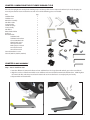
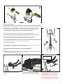
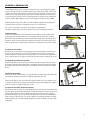
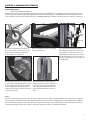
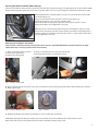
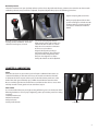
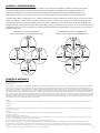
Indoor Cycle Assembly Service Manual
Pro Series:
400 Pro
300 Pro
200 Pro
100 Pro
Chapters:
1. Unpacking the CycleOps Indoor Cycle.......1
2. Bike Assembly.............................................................1
Attach Stabilizer Feet
Attach Handlebars
Seat Assembly
Attach Pedals
Attach Console Bracket and Console
Leveling the Bike
3. GENERAL USE...............................................................5
4. COMMON ADJUSTMENTS........................................5
Flywheel Adjustment
Replacing Hub Batteries
Brake Adjustment
Replacing Brake Pads
Replacing Resistance Knob
5. Lubrication................................................................9
6. eLECTRONICS......... ......................................................11
7. RF INTERFERENCE/group use case.....................
8. WARRANTY.....................................................................11
1
CHAPTER 1:Unpacking the CycleOps Indoor Cycle
Place the box upright and cut the plastic binding straps. Lift the top of the box to expose the Indoor Cycle and packaging. Remove all parts from the box and foam inserts and ensure all the following parts are included:
Part Stabilizer front
Stabilizer rear
Main bike assembly
Handlebar tube
Seat post tube
Saddle w/ clamp
Seat assembly
Handlebar
Water bottle holder
Pedal set
IP hardware kit
Stabilizer bolts
Stabilizer bolt washers
Console Bracket bolts
Water bottle spacer 4mm Spacer bolts
Multi-purpose wrench
5mm allen wrench
4mm allen wrench
Console Bracket w/ screw
Console (400 Pro, 300 Pro, 200 Pro)
Qty
1
1
1
1
1
1
1
1
1
1
1
8
8
2
1
2
1
1
1
1
1
Chapter 2: Bike Assembly
Step 1: Attach Stabilizer Feet
1.Note the difference between the front and rear stabilizer feet. The larger foot with wheels goes in the rear of the IC.
2. Align the rear base of the frame with the rear stabilizer and secure it with four 6mm bolts with washers. NOTE: Tighten
the inner bolts first, and then proceed to the outer bolts to ensure the foot is secured properly and evenly.
3. Repeat with the front stabilizer.
Rear Stabilizer Feet
Front Stabilizer Feet
1
Step 2: Attach Handlebars
Insert the Handlebar post into the head
tube and secure it using the L-handle.
Slide the plastic shim onto the D-shaped
tube on the water bottle holder.
Secure the water bottle holder and spacer
to handlebar assembly using 2- 4mm
allen bolts
arefully slide the handlebar onto the
C
handlebar post.
Slide the water bottle holder and plastic
spacer onto the handlebar assembly.
Once the handlebar is in place,
secure it with the L-shaped
tension handle.
Step 3: Seat Assembly
A. Loosen the L-handle on seat clamp assembly on the seat tube.
C
B
A
B. Attach the saddle to the seat post clamp, using a 6mm Allen wrench.
Make sure both rails of the saddle are properly seated in the clamp
and tighten the 6mm Allen bolt. If desired, any standard bicycle saddle
can be attached to the CycleOps Indoor Cycle. Ensure the saddle is
level and parallel to the floor for optimum comfort. The seat may need
tighening after first few uses.
C. Once the Saddle is level and properly tightened in the clamp, attach
the plastic end cap with two of the included screws.
D. In some instances, a shorter seat post is required for individuals
under five feet tall. You can replace the standard seat clamp mechanism with part # 16616. Contact Saris Cycling Group to order this part.
Follow the instructions provided with that part for installation.
2
B
Step 4: Attach Pedals
The CycleOps IC includes a standard pedal set; however, to mimic the fit and feel of your
own bike you may also attach your own pedals per the manufacturers’ specifications.
Note that pedals are designed to be installed specifically on the right or left-hand
side of the IC. Improper installation can result in damage to the crank. Damage
caused by improper crank installation is not covered under warranty.
Attach your pedals onto the bike with a pedal wrench. Typically, each
pedal is marked with an “R” or an “L” on the very end of the spindle past the threads.
This mark indicates which side of the bike the pedal is intended to mount on.
This is important since the thread directions are different for each pedal.
A. Locate the pedal that has the “R” on the spindle. This pedal is for the right side crank
arm of the bike (chain guard side) and is right hand threaded
(turn clockwise to tighten).
B. Locate the pedal that has the “L” on the spindle. Turn the spindle left (counter-clockwise) to tighten as the “L” spindle is reverse threaded.
A
B
Step 5: Attach Console Bracket and Console (If applicable)
Bracket
When first setting up the CycleOps IC you must attach the console bracket to the bike. To
do this, follow the instructions below:
Place bracket onto the handlebars as
shown.
Insert screws through console bracket,
handlebar bracket, and tighten together.
Slide the console down completely down
onto the bracket. To ensure a solid connection between the console and the
bracket make sure the contact points
between the console and bracket remain
clean and free from moisture or debris.
3
Batteries: The console ships with batteries. In the event the batteries need to be replaced over time, follow these simple steps:
Remove the back cover with a small Phillips-head screwdriver.
Remove batteries.
Replace with fresh AAA batteries, paying attention to properly line up the +/- poles.
Replace battery door and secure with small Phillips-head screwdriver.
Leveling the bike
Once the above assembly instructions have been followed, move the bike to where it will be used and level it properly. To level the
bike, adjust the leveling feet underneath the stabilizers until there is no rocking or movement of the bike. It is important to level
the bike for long term care.
Leveler Lock
You can secure the feet by tightening the
leveler locks.
IMPORTANT! How To Zero Torque
The torque must be zeroed to ensure that the console displays the most accurate power information. If the
instantaneous power is positive or negative, the torque needs to be zeroed. These operations must be done
with NO tension on the chain and with NO force being placed on the pedals. Also, the transmission icon must
be illuminated.
To zero torque, first ensure the transmission icon is showing. Then press [DOWN ARROW] to move the cursor
to [WATTS]. Press [SELECT] to change to [INCH-LBS]. Then hold down [SELECT] again until “0” is shown (about
10 seconds). Press [SELECT] to return to [WATTS]. The torque value will now read zero.
If the torque does not zero on the first attempt after ~10 seconds, repeat the procedure.
4
Chapter 3: GENERAL USE
The CycleOps Indoor Cycle is easy to use. Simply sit on the cycle, tighten the pedal
straps and begin cycling. The CycleOps indoor cycle allows the user full control over
resistance by simply adjusting the resistance knob. Typically, lower resistance levels
enable you to pedal at a faster pace, placing increased demand on the cardiovascular system. Higher resistance levels will typically deliver a greater muscle/endurance
workout at lower RPMs. RPM parameters in the program range from 60-110 RPM.
Additionally, the indoor cycle offers seat and handlebar adjustments, allowing the
CycleOps indoor cycle to be configured to each user’s comfort zone.
This section provides the instructions for making seat adjustments,
handlebar adjustments, pedal strap adjustments, and for controlling resistance.
Seat Adjustments
Proper seat height helps ensure maximum exercise efficiency and comfort, while
reducing the risk of injury. Adjust the seat height so that the knee joint is slightly
flexed when the extended leg is at the bottom of the pedal stroke. Once the proper
height has been achieved, adjust the seat forward or back so that when the feet are
in the 3 o’clock and 9 o’clock positions, the knees are directly over the pedal spindle.
To adjust the seat height:
Dismount the cycle. Turn the seat height pop-pin counterclockwise and pull out on
the pin to release it from its current preset location. Raise or lower the seat to the
desired height, then gently release the pop-pin. Raise or lower the seat slightly, if necessary, until the pop-pin engages a preset hole. Turn the pop-pin clockwise to secure.
Fore-aft
Handle
POP-PIN
To adjust the seat horizontal position:
Dismount the indoor cycle. Loosen the seat fore-and-aft tension handle by turning
the handle counterclockwise. Move the seat forward or back to the desired position,
then tighten the tension handle by turning clockwise. Be sure to tighten the handle
firmly.
Handlebar Adjustments
Proper position for the handlebar is based primarily on comfort. Typically, the handlebar should be positioned even with or slightly higher than the seat.
Dismount the indoor cycle Turn L-handle counterclockwise to release it from its current preset location. Raise or lower the handlebar to the desired height, then tighten
L-handle. Turn the L-handle clockwise to secure.
Fore-aft
Handle
POP-PIN
To adjust the handlebar horizontal position:
Dismount the indoor cycle. Loosen the handlebar fore-and-aft tension handle by turning the handle counterclockwise. Move the handlebar forward or back to the desired
position, then tighten the tension handle by turning clockwise. Be sure to tighten
the handle firmly. As a general guideline, handlebar fore-and-aft can be determined
by placing one’s elbow on the nose of the saddle and extending the fingers straight.
Adjust handlebar fore-and-aft until the fingertips touch the handlebar near the stem
and tighten.
5
Pedal Strap Adjustment
The pedal straps should be adjusted to hold the foot snugly in the pedal.
To adjust the pedal straps:
Place each foot in the toe clip until the ball of the foot is over the pedal axle. The
front of the shoe may not completely fill the toe cage. Rotate the pedals until one
foot is within arms reach, then tighten the webbed cloth buckle until the cage of
the toe clip is snug around the foot. Repeat for the other foot. Point your toes and
knees directly forward to ensure maximum pedal efficiency.
Resistance Control
Pedaling resistance is controlled by the resistance knob located behind the handlebar. Resistance adjustments can be made while riding to vary the intensity of your
workout.
To adjust pedaling resistance:
To increase resistance, turn the knob clockwise (+); to decrease resistance, turn the
knob counterclockwise (-).
In case of emergency, you may press directly down on the knob to bring the flywheel to an abrupt stop.
6
Chapter 4: common adjustments
Flywheel Adjustment
Chain tension/Flywheel Alignment
Over time, the chain on your CycleOps IC will stretch due to the load applied to it. The following instructions will aid you in properly tensioning the chain and aligning the flywheel in the frame of the CycleOps IC. CAUTION: Improper chain adjustment will
cause premature wear and may void the warranty. ** CAUTION: NEVER put hands into or near the drive train while it is motion! **
1/2”
Acorn
Nut
Axle Lock
Nut
1/2”
ove the crank arms back and forth. If
M
there is more than 1/2” movement in the
chain before the flywheel rotates, the
chain needs to be re-adjusted.
Using a 3mm Allen wrench, remove the
chain guard bolts (3).
10 mm chain
tension
Once the acorn nuts are loose, you can adjust the alignment of the flywheel as well
as the chain tension. Using a 10 mm box
wrench, adjust the tensioning hardware
until the desired chain tension is achieved
evenly on both sides.
se a 17mm cone wrench to hold the
U
axle locking nuts into place. Do not turn
the wrench, it is only to be used as a stabilizer. With your other hand, use a 15mm
box wrench to loosen the acorn nuts on
the axle. Repeat this process on each side
of the flywheel.
Check the alignment of the flywheel
against the seat post of the CycleOps
IC. Once the proper tension had been
achieved and the flywheel is properly
aligned, tighten the Acorn nuts to 75
in-lbs.
NOTES:
Be sure to make small adjustments to the drive train. Adjust both sides of the tensioning hardware. Only adjusting one side will
lead to improper flywheel alignment and unwanted drive train wear and/or noise. Adjusting the tension/alignment is a difficult
task and improper adjustment can lead to premature chain/cog wear. This is not covered under warranty. The chain tension has
been adjusted properly when there is little or no play felt when the pedals are rocked back and forth.
7
Replacing Hub Batteries 400 Pro/300Pro (AA type)
Over time, the batteries that power the electronics in the hub will need to be changed. The split battery cap on the Club Pro 300PT
flywheel was designed to make this task as easy as possible. When it is necessary to change the hub batteries, follow these steps:
Rotate the flywheel to a position where you can access the Allen bolt on the handle
side of the battery cap.
Using a 2.5 mm Allen wrench, remove the screw on the battery cap.
Pull the plastic battery cap out via the molded handle.
Replace the batteries, paying close attention to properly line up the +/- poles.
Replace the battery cap and tighten the set screw.
NOTE: If you have a wired console, the hub requires 2 E90 batteries. Using a 2.5 mm
Allen wrench, remove the side of the plastic battery cap with the “teeth.” Replace the
batteries, paying close attention to properly line up the +/- poles. Replace the battery
cap and tighten the set screw.
Replacing Sensor Batteries Comp 200E
Over time, the 3 volt lithium battery in the speed/cadence sensor in the COMP 200E indoor cycle will need to be changed.
Follow these steps to change speed/cadence sensor battery:
1. Using a 3mm Allen wrench, remove
the three chain guard bolts.
2. Remove the chain guard.
3. Using a 5 mm Allen wrench, remove the bolt for the
bracket arm that holds the speed/cadence sensor.
Fig. 2 – Remove Bolt
Fig. 3 – Slide Sensor Out of Frame
Fig. 1 – Remove chain guard
4. Using a quarter, remove the battery cover on the back of the sensor by turning counterclockwise approximately one half turn.
5. Replace the battery.
Fig. 4 – Remove Battery Cover
Fig. 5 – Battery
6. Reattach the bracket arm and the speed/cadence sensor inside indoor cycle frame.
NOTE: After replacing the battery, the indoor cycle console must relearn the coded ID for the speed/cadence sensor.
Refer to the Indoor Cycle Console Manual for instructions (available at www.cycleops.com).
8
Brake Adjustment
The brake mechanism on your CycleOps indoor cycle has been adjusted at the factory. However, over time due to chain stretch
and brake pad wear, it may need to be adjusted. To replace/adjust brake pad, use the following procedure:
Tighten clamping bolt to 50 in-lbs.
When properly adjusted, the Indoor
cycle should register around 30 watts
at 90rpm with no resistance applied
(can only be validated on Club Pro
300PT)
Fig 1
Back off resistance until it the knob stops
turning (counter-clockwise). Then turn
clockwise 180 degrees (1/2 turn)
L oosen the clamping bolt with an
Allen wrench (*Note, early models use
a 4mm bolt, later models use a 5mm
bolt). Be sure to note the orientation
of all necessary hardware.
Align the brake pad by sliding it
towards the flywheel. Stop when the
pad just touches the flywheel. Note
that you must align the arc of the
brake pad with the arc of the flywheel.
Chapter 5: lubrication
Chain
Over time, the chain on your indoor cycle will require additional lubrication. It is
recommended that you lube the chain every six months to maximize chain life.
To lubricate the chain on your indoor cycle, use the lubrication port that is at the
back of the chain guard Liberally spray a Teflon-based lubricant onto the chain.
Be sure each link gets lube. Be careful not to over-lubricate the chain as excess lube
will drip out of the chain guard and can stain floors/carpet.
Nuts & Bolts
It is recommended that you put a light coating of lithium grease on the threads of the
following hardware to ensure proper tightening and to prevent the parts from seizing
over time:
•Stabilizer bolt threads
•Rubber feet threads
•Pull-pin threads
•Pedal spindle threads
Lube Port
9
Preventative Maintenance
Performing necessary preventative maintenance is key to keeping your CycleOps IC in proper working condition.
Following these recommended maintenance procedures will help extend the life of your CycleOps IC.
Daily
Wipe Down/Cleaning:
After your ride, be sure to release all tension from the resistance mechanism. Wipe down the entire unit using an absorbent cloth.
A standard bicycle polish can be used on the painted parts of the IC. Focus on areas where sweat can settle. Give particular attention to the following:
• Handlebar
• Seat/Seat tube
• Flywheel
• Frame
• Chain Guard
• Resistance Knob
• Handlebar Tube
• Stabilizers
**Never use abrasive cleaning liquids or petroleum-based solvents when wiping down the bicycle.
Inspection/Adjustment:
Inspect the CycleOps IC for any loose parts, nuts, bolts, etc. Pay special attention to the
following:
• Pedals
• Seat Assembly bracket
• Handlebar assembly bracket
• Crank arms – tighten to 75 in-lbs.
Weekly
Perform all daily maintenance recommendations. In addition:
• Inspect screws on console bracket. Tighten if necessary.
• Inspect and properly tighten brake pads.
• Properly tighten pedals and all hardware attaching toe clips/straps (if applicable)
• Inspect handlebar clamp assembly.
• Inspect seat clamp assembly. Tighten clamp bolt if necessary
• Inspect stabilizer feet. Tighten if necessary.
• Inspect flywheel. Check for proper alignment. Tighten acorn locking nuts to 75 in-lbs.
• Inspect crank/bottom bracket interface. Tighten to 75 in-lbs
Monthly
• Perform all Daily and Weekly maintenance recommendations. In addition:
• Perform thorough cleaning of the CycleOps IC. This includes:
• Remove handlebar tube and seat tube and clean both the stainless steel tube as well as inside the plastic sleeve. Inspect sleeves
for scoring. Replace if no longer properly securing vertical adjustment.
• Clean the underside of the stabilizer feet.
• Remove console bracket and clean the handlebar assembly
• Clean the flywheel with mild detergent or a damp cloth
• Check the chain tension to ensure that the chain is properly adjusted. See “Adjusting the Chain Tension” for instructions
• Inspect plastic sleeves for damage. Replace if necessary.
• Inspect brake pads for wear. Replace pads if there is less than 2mm of felt pad exposed.
• Lube the drive train. See “Lubrication” for instructions.
Chapter 6: ELECTRONICS
Specifications
Accuracy +/-1.5% (400 Pro/300Pro)
Signal Transmission Digital RF
Operational Temperature 0 to 40 degrees c or 32 to 104 f
Battery Life (Hub) 1000 hours approx.
Battery Life (Console) 100 hours approx.
Battery Type (Hub) AA type 1.5 volt 2 ea)
Battery Type (Console) AAA type, 1.5 volt (3 ea)
Freehub fixing bolt torque 400-450 inch-lbs.
10
Chapter 7: RF interference:
If during use you are experiencing wireless drop out this is due to frequency interference. Wireless Internet access points, microwaves, cordless phones, or other wireless devices may cause frequency interference. To mitigate the chance of interference set wireless access points to the lowest channel possible, and keep bikes away for interfering devices. To change the channel on your access point, please consult your manufacturers documentation or your technology staff.
CycleOps utilizes ANT+ technology to ensure a robust and reliable connection between the various sensors used in our products.
Sensors are defined as power meter sensors, heart rate strap sensors, cadence sensors, speed sensors, and controlled resistance
sensors. However, there is a limit to the number of sensors that can operate in a given environment. Practically speaking, when
riding by yourself or with others using less than 30 total ANT+ sensors you should see no more than a 1% loss in data due to communication errors in your sensors. However, in an environment with more than 30 total ANT+ sensors you may see an increase in
communication errors.
Optimal Indoor Cycle Configuration for Wireless Communication in Group Environment
Optimal Indoor Cycle Configuration for
Wireless Communication in Group Environment
Undesirable Indoor Cycle Configuration for
Wireless Communication in Group Environment
Undesirable Indoor Cycle Configuration for Wireless Communication in Group Environment
Less than
2 meters
2 meters
2 meters
2 meters
2 meters
2 meters
2 meters
Less than
2 meters
Less than
2 meters
Less than
2 meters
2 meters
Less than
2 meters
Less than
2 meters
Less than
2 meters
Less than
2 meters
2 meters
Chapter 8: WARRANTY
Frame - Lifetime
Parts - 3 years (excludes wear items)
Electronics - 1 year
Saris Cycling Group, Inc. warrants its PowerTap products against defects in manufacturing and workmanship for a period of one year, beginning at the date of purchase, or from the date
of manufacture in the absence of a proof of purchase. In the event of a warranty issue, Saris Cycling Group, Inc. will repair or replace the item at its discretion. Saris Cycling Group, Inc. is
not responsible for any indirect or consequential costs or damages associated with the warranty of the product. Our products are not covered under warranty in cases exhibiting signs of
abuse, improper maintenance or installation, crash, using the product with non-compatible components, or using the product for purposes for which it was not designed. This warranty is
also void if the product has been modified from its original form, including changes in aesthetics, serial numbers or logos. Saris Cycling Group Inc., is not responsible for basic hub maintenance, such as re-packing bearings and bearing adjustments. Warranty Procedures If it appears that a PowerTap component is not working properly, please take the time to inspect and
troubleshoot the system as best as possible. In many instances, solutions may be as simple as replacing a bearing or adjusting a sensor. Often small parts can repaired at the shop, instead
of the longer and more expensive option of sending the unit back for repair. If you feel the need to warranty your PowerTap, please return your product through the channel that you
purchased it from or contact Saris Cycling Group, Inc. at 1-800-783-7257.
Copyright
Copyright 2009. All rights reserved. No part of this publication may be copied, photographed, reproduced, translated, transmitted electronically or placed on digital media without the prior written consent of Saris
Cycling Group, Inc.
Trademarks
Saris Cycling Group, Inc , PowerTap and the PowerTap logo, are all registered trademarks of Saris Cycling Group, Inc. All other product, brand, or trade names used in this manual may be trademarks or registered trademarks of their respective owners.
Modifications
Saris Cycling Group, Inc reserves the right to make improvements and/or updates to the products described herein at any time without notice.
FCC Statement of Compliance:
Statement of Compliance for FCC and Industry Canada:
“This device complies with Industry Canada and Part 15 of the FCC Rules. Operation is subject to the following two conditions: (1) This device may not cause harmful interference, and (2) this device must accept any
interference received, including interference that may cause undesired operation.”
The term “IC:” before the radio certification number only signifies that Industry Canada technical specifications were met.
Changes or modifications to this device not expressly approved by the party responsible for compliance with FCC regulations (the manufacturer) could void the user’s authority to operate the equipment.
This equipment has been tested and found to comply with the limits for a Class B digital device, pursuant to part 15 of the FCC Rules. These limits are designed to provide reasonable protection against harmful
interference in a normal installation.This equipment generates, uses and can radiate radio frequency energy and, if not installed and used in accordance with the instructions, may cause harmful interference to radio
communications. However, there is no guarantee that interference will not occur in a particular installation
11
12
16417G 0907
13