1
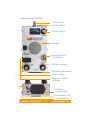
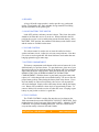
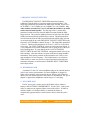
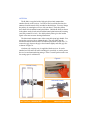
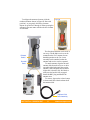
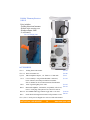
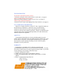
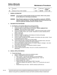
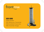
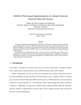
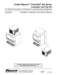
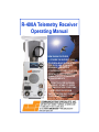
R-400A Telemetry Receiver Operating Manual NEW R-400A FEATURES COVERS THE ENTIRE 216.000 220.000MHz BAND IN 1kHz STEPS FOR QUICK AND ACCURATE FREQUENCY SELECTION SUPER SELECTIVE 8 POLE SSB CRYSTAL FILTER FOR GREATER RANGE IN HIGHLY CONGESTED RF ENVIRONMENTS .5 PPM TCXO FOR SUPERIOR FREQUENCY STABILITY UNDER ALL TEMPERATURE CONDITIONS NEW 4 POSITION RF GAIN SWITCH FOR PINPOINT CLOSE-IN POSITION ACCURACY INTRODUCTION Congratulations on purchasing the new R-400A Telemetry Receiver. This receiver is an exceptional value for a synthesized receiver covering any frequency between 216.000 and 220.000MHz with no gaps in coverage. This not only allows you to hunt with multiple birds transmitting at the same time, but multiple dogs also. The R-400A is supplied with a folding high gain, and very directional antenna which mounts directly to the receiver and rivals a Yagi in performance. No coax is required, allowing one handed operation. A standard 9 volt alkaline battery powers the unit and is easily changed using a fingernail. Not only is the R-400A extremely sensitive to hear the weakest telemetry signals, it also employs very effective filters to eliminate unwanted interference sources. The synthesized design provides excellent temperature stability with no drift in frequency settings. A four step attenuator allows full receiver sensitivity for longest range or reduced sensitivity for extremely close-in tracking to a few inches. The R-400A employs a large, full range, speaker for rich sounding loud audio. A very sensitive signal strength meter also doubles to let you know when the battery needs replacing. A rugged, light weight, aluminum case is standard as well as a 3.5 mm mono headphone jack and adaptor for the larger 1/4” headphone plugs. A standard circ., 5.5mm x 2.1mm, center positive, power jack allows the R-400A to be powered from an external 914VDC source. [email protected] Call Toll Free 1.800.854.0547 1 www.com-spec.com TABLE OF CONTENTS -R-400A SPECIFICATIONS -R-400A RECEIVER CONTROLS 1. ANTENNA JACK 2. METER 3. RF GAIN SWITCH 4. SPEAKER 5. ON-OFF-BATTERY TEST SWITCH 6. VOLUME CONTROL 7. BATTERY COMPARTMENT 8. TUNE CONTROL 9. FREQUENCY SELECT SWITCHES 10. HEADPHONE JACK 11. DC POWER JACK -ANTENNA -USING TELEMETRY TO FIND YOUR BIRD OR DOG -ORDERING -TROUBLESHOOTING GUIDE -FCC COMPLIANCE INFORMATION -ABOUT US -WARRANTY Page 2 Page 3 Page 4 Page 4 Page 4 Page 5 Page 5 Page 5 Page 5 Page 5 Page 6 Page 6 Page 6 Page 7-8 Page 9 Page 10 Back Cover Back Cover Back Cover Back Cover SPECIFICATIONS Frequency range: Continuous from 216.000 to 220.000MHz Sensitivity: -150dBm Channel steps: 1kHz with 500Hz fine tuning Antenna connector: BNC female RF attenuator: -20, -40, -70dB switchable Battery: 9 volt replaceable alkaline Size: 6.2"x3.5"x1.4", less projections Overall size with antenna folded: 12"x4.75" Overall size with antenna extended: 20.25"x11.25" Weight: 18oz without antenna, 31oz with antenna Supplied with pistol grip Yagi antenna that allows one handed operation, detaches and can be used alone, and folds for easy carrying Call Toll Free 1.800.854.0547 2 www.com-spec.com R-400A RECEIVER CONTROLS 1. ANTENNA JACK 2. LIGHTED METER 3. RF GAIN SWITCH 4. SPEAKER 5. ON-OFF-BATTERY TEST SWITCH 6. VOLUME CONTROL 7. BATTERY COMPARTMENT 8. TUNE CONTROL 9. FREQUENCY SELECT SWITCHES 7. BATTERY COMPARTMENT 10. HEADPHONE JACK 11. DC POWER JACK Call Toll Free 1.800.854.0547 3 www.com-spec.com 1. ANTENNA JACK Industry standard BNC female antenna jack accommodates either the supplied directional antenna, standard coax lead with external yagi antenna, or auto rooftop antenna. Just push the plug into the jack and twist clockwise to lock into place. Twist counterclockwise and pull to remove. 2. METER The lighted meter is used to measure the relative strength of the incoming signal. Use the VOLUME CONTROL and RF GAIN SWITCH to set the meter in the center of the scale. Use the changes in upward meter movement while receiving your transmitters pulsed signals to help get good directional information from your antenna position. The meter is also used to measure battery condition when the ON-OFF-BATTERY TEST switch is in BATTERY TEST. The battery indication box on the bottom of the meter scale will indicate the battery voltage remaining in the battery. A 7 on the meter is 7 volts remaining (almost totally discharged battery), a 9 on the meter indicates 9 volts remaining (a good battery). Replace the battery when the needle falls below 7. 3. RF GAIN SWITCH The RF GAIN SWITCH is a 4 position rotary switch that is used to attenuate the signal going from the antenna to the R-400A. This is so the R400A is not overloaded by a strong signal. In HIGH there is no attenuation, therefore the R-400A is listening with full sensitivity. In the second CCW (counter clockwise) switch position approximately 20dB of attenuation is inserted between the antenna and the R-400A. In the third CCW switch position another 20dB is inserted for a total of 40dB. In the LOW or full CCW switch position another 30dB is inserted for a total of 70dB. To DF your bird, always start in the HIGH position to make sure it can be heard and you are satisfied with the pitch of the received tone (as set by the TUNE CONTROL). If you are able to hear your transmitter, change switch positions to the second CCW position and see if it can still be heard. If it can not, go back to HIGH, reduce the volume so the meter indicates around half scale and turn around in order to find the strongest signal strength. This will show what direction your bird is. Walk or drive in that direction until you can move the RF GAIN SWITCH to the second CCW position and still hear the signal. Continue to walk or drive in the direction of the strongest signal strength until you can change the RF GAIN SWITCH to the third CCW position. Finally, when you can change it to the LOW or full CCW position, you should be in sight of it. Call Toll Free 1.800.854.0547 4 www.com-spec.com 4. SPEAKER A large, full audio range speaker is used to provide very good sound quality. Keep liquids, dirt, sand, and other foreign material from falling into the small holes in the speaker grill. 5. ON-OFF-BATTERY TEST SWITCH In the OFF position, no battery current is drawn. This is how the switch should be left when the receiver is not in use. When switched to the ON position, the receiver is active and drawing current from the battery. In the BATTERY TEST position, the condition of the battery under load is tested and the results are available on the meter. 6. VOLUME CONTROL The volume control is used to raise or lower the audio level to the speaker and meter circuit. Adjust it to suit your own preference. Note that it is easier to track a signal that falls about mid meter scale rather than one banging against the upper meter stop. 7. BATTERY COMPARTMENT The battery compartment on the bottom of the receiver houses the 9 volt alkaline battery in a pull-out drawer. To open the drawer, place one of your fingernails in the slot on the bottom edge of the drawer and lift up with your finger until the drawer snaps upward. Then pull the drawer out. DO NOT REMOVE THE TWO SCREWS HOLDING IN THE BATTERY COMPARTMENT! With the drawer in your hand, pop up the battery and replace it if it is discharged with a new alkaline battery. Be sure to note the proper battery polarity when placing the battery back in the drawer. If you force the battery in with reversed polarity, the receiver will not work but will not be damaged. Simply remove the battery drawer and flip the battery over. Battery life at moderate volume levels is approximately 4 hours. To conserve battery life, turn the receiver off when not in use. Keeping a spare battery in your pocket or vehicle is a good idea. 8. TUNE CONTROL The TUNE CONTROL is used to fine tune the receiver between the 1kHz increments shown on the FREQUENCY SELECT SWITCHES. Each number between 0 and 9 represent approximately 100Hz. Adjust the TUNE CONTROL for a pleasant sounding audio tone. This tone is different for everyone but usually is between 500 and 1500Hz. Call Toll Free 1.800.854.0547 5 www.com-spec.com 9. FREQUENCY SELECT SWITCHES The FREQUENCY SELECT SWITCHES control the frequency synthesizer in the R-400A so it operates on the selected frequency. The single digit pushwheel switch shows the MHz range selected. It will be a 6 for 216MHz, a 7 for 217MHz, an 8 for 218MHz, or a 9 for 219MHz. Any other number selected (0,1,2,3,4, or 5) will mute the R-400A so no audio can be heard from the speaker. The first digit of the 3 position kHz pushwheel switch selects the desired 100kHz increment within the MHz range selected. The second or middle pushwheel switch selects the desired 10kHz increment within the 100kHz range selected. The third pushwheel switch selects the desired 1kHz increment within the 10kHz range selected. An example might be to set the FREQUENCY SELECT SWITCHES to the frequency of 216.025MHz as shown on page 3. The single MHz pushwheel is set to 6. The three kHz pushwheels are set to 0, 2, and 5 as viewed from left to right. The TUNE CONTROL is then set to the tone pitch desired. It is very important to try out the transmitters you are going to use in the field before needing them. It is also helpful to have a list of CHANNEL SELECT SWITCH and TUNE CONTROL settings that match each of your birds and dogs. Note that with the exception of the newest programmable transmitters, the frequency marked on the transmitter case is only a close approximation of its real frequency. The R-400A however is accurate to within 100Hz, so make sure you have selected and written down the real transmitter frequency as shown on the CHANNEL SELECT SWITCHES before deployment. 10. HEADPHONE JACK A standard 3.5 mm (1/8”) mono headphone plug can be inserted into this jack for use in noisy environments. If a stereo headphone is plugged in, audio will be normally only be heard in one ear. When a plug is inserted into the jack, the internal speaker in the R-400A is disconnected. The QA-8 adaptor is supplied for headphones with the larger 1/4” male plug. 11. DC POWER JACK The DC power jack is used to power the R-400A with or without a battery in the BATTERY COMPARTMENT. Use the CM-1, 12vdc power cable, to connect to the cigarette lighter socket in the vehicle. If either an alkaline, NiMH, or Li-Polymer battery is installed, the battery is automatically bypassed and no current is drawn from it when this jack is used. Call Toll Free 1.800.854.0547 6 www.com-spec.com ANTENNA The R-400A is supplied with a high gain, directional antenna that attaches directly to the receiver. In order to find your birds direction, the antenna elements must be fully extended as shown below. You may change the polarity by rotating the receiver with your hand. The below photos show both vertical and horizontal polarization. Hold the R-400A as shown in the photos and try both vertical and horizontal polarization while turning your body around in a circle. See which polarity either gives the loudest signal or the most accurate bearing information. The directional antenna comes with a removable pistol grip handle. You can use the receiver with or without the grip. The grip slides into the bracket beneath the antenna and will lock into place with a small click. To remove the grip, depress the grip release button slightly and slide grip free as shown in Figure A. A holster style carrying case is supplied with the receiver. It can be attached to a belt and worn while searching for your bird, or used to protect the receiver and antenna during storage. There is a small pocket on the case for storing spare 9 volt batteries. Figure A Vertical Polarity Grip Release Button Horizontal Polarity Call Toll Free 1.800.854.0547 7 www.com-spec.com To collapse the antenna elements, slide the Figure B numbered buttons shown in Figure B. Start with position 1 as you gently fold in the elements. Repeat for positions 2 through 4. When opening the antenna it does not matter which order the elements are unfolded. Release Button Dovetail Base The directional antenna can be used in two ways. The R-400A receiver can be mounted on the FA-3 antenna for one handed operation or the CA-4 coax assembly can be attached so that the antenna and receiver can be separated. To attach antenna, align the dovetail antenna slide from the receiver or cable assembly with the dovetail base on the antenna. Slide and push forward until a slight click is heard or felt. Pull back to make sure the latch is fully engaged. Install the BNC plug attached to the antenna coax. To remove, depress the release button as shown and slide either backwards off the antenna slide. Optional CA-4 Coax Assembly Call Toll Free 1.800.854.0547 8 www.com-spec.com USING TELEMETRY TO FIND YOUR BIRD OR DOG 1. Install a working transmitter with a known good battery or batteries on your bird or dog. 2. Momentarily put the ON-OFF-BATTERY TEST SWITCH on the R-400A in the BATTERY TEST position and see if the battery tests O.K. on the meter. If questionable, be sure to carry a spare with you. 3. Unfold the FA-3 directional antenna. Turn the ON-OFF-BATTERY TEST SWITCH to ON and set the VOLUME CONTROL to a comfortable listening level. 4. Dial in the FREQUENCY SELECT SWITCHES to the frequency shown on your transmitter. Use the TUNE CONTROL to fine tune the pitch of the received audio tone. You should be able to hear your transmitter, if it is close, with the RF GAIN SWITCH in the LOW position. 5. If you can not, find out why before you release your bird. It is absolutely imperative that you test out each transmitter before release. Remember, or better yet, write down the FREQUENCY SELECT SWITCH and TUNE CONTROL settings for the transmitter you are now going to track or direction find (DF). 6. With the transmitter a reasonable distance away, place the RF GAIN SWITCH in the HIGH position, hold the R-400A level in your hand, use vertical antenna polarity to start with and turn around in a full circle and see if you hear the transmitter. If you do not, try horizontal antenna polarity and try again. If you still do not, you will have to stand on a truck bed, building roof, close by hill, etc. in order to get a more line of sight path between the transmitter and receiver. 7. If you hear the transmitter, note its azimuth (direction) and head towards it. As the signal gets stronger, change the RF GAIN SWITCH to one of the two middle positions. Raise or lower the VOLUME CONTROL to keep the meter indication around mid scale. 8. Recheck for proper direction and continue. When you get close to the transmitter, you can change the RF GAIN SWITCH to the LOW position and walk towards the strongest signal until you find it. 9. It is a very good idea to try a few dry runs having someone else hide the transmitter with you trying to find it using the above method. Call Toll Free 1.800.854.0547 9 www.com-spec.com R-400A Telemetry Receiver $499.95 Price includes: -Folding directional antenna -Holster style carrying case -Headset adapter cable -9 volt battery. FA-3-C Carrying Case ACCESSORIES * FA-3 $59.95 Folding directional antenna * FA-3-C Receiver/antenna case $10.00 * QA-8 Mono headphone adaptor , 1/4” female to 3.5 mm male $9.95 CA-4 Coax Assembly 5’ long with molded BNC connectors, barrel connector, and clamps assembled on antenna slide so antenna can be used when detached from R-400A $11.95 CM-1 12vdc Cigarette lighter power cable $12.95 RA-13 Monaural headphone, comfortable, well padded, coiled cord, mono 3.5 mm plug, and separate level control for each ear $36.95 RA-216 216-220Mhz folded yagi antenna w/grip and 5' coax lead $125.00 RA-9 $49.95 Omni directional magnet mount auto rooftop antenna w/coax * FA-3, FA-3-C and QA-8 are shipped at no extra cost with each R-400A Call Toll Free 1.800.854.0547 10 www.com-spec.com TROUBLESHOOTING The R-400A sounds different than it used to: -Test battery and replace if the needle is below 8 on the meter. (see page 4) There is no audio coming from the speaker: -Make sure the MHz frequency switch is set to 6,7,8 or 9. (see page 6) Unable to hear signal from transmitter: -Set the RF Gain Control to the high position, fully clockwise. (see page 4) FCC COMPLIANCE INFORMATION This device complies with Part 15 of the FCC rules. Operation is subject to the following two conditions: (1) This device may not cause harmful interference, and (2) this device must accept any interference including interference that may cause undesired operation. Changes or modifications not expressly approved by Communications Specialists, Inc. could void the user's authority to operate the equipment. ABOUT US Communications Specialists, Inc. has been building quality electronic products that the land mobile radio and wildlife telemetry industries have come to rely on for over 40 years. At our Orange California factory, we utilize the latest in surface mount assembly technology to assure consistent quality throughout our entire product line. WARRANTY The R-400A is warranted to be free of defects in materials and workmanship for a period of one (1) year from the date of purchase. You may also return it within 30 days for a full, no questions asked, refund. If you need to take advantage of our warranty, follow these steps: 1- Securely repackage the R-400A. 2- Include a note as to the nature of the problem, if known. 3- Include your shipping address and a daytime phone number or E-Mail address. 4- Ship to: Communications Specialists, Inc. 426 W. Taft Ave. Orange, CA 92865 [email protected] Rev. 07-10-12-PL