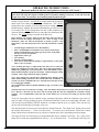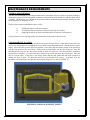
1
AMERICAN ENERGY SYSTEMS INC.
INSTALLATION, OPERATION AND MAINTENANCE MANUAL
HARVESTER BIOMASS SOLID FUEL STOVE
MODEL HR-01 – HR-01-B
USA & CANADA TEST:
ASTM E1509-04, UL 1482,
ULC S627, ULC/ORD C1482 (and ULC S628
if listed for fireplace insert installation in Canada)
Oregon Administrative Rules 814-23-909
TESTED BY:
WARNOCK HERSEY
MOBILE HOME APPROVED
WARNING: If the directions in this manual are not followed exactly, a fire
may result causing property damage, personal injury or loss of life.
FOR YOUR SAFETY
Do not store or use gasoline or other flammables (vapor or liquids) in or
around the vicinity of this appliance.
Installation and repair must be performed by a qualified service agency.
Always check with local jurisdiction or code agency before installing this
product. Local jurisdiction may require a permit prior to installation.
Rev. Update 01/2012
Table of Contents
SAFETY NOTES:………………………………………………………………………………………………3-5
EPA STANDARDS:…………………………………………………………………………………........5
LISTING / TESTING AGENCY (AUTHORITY)………………………………………………………..5
CERTIFICATION SAFETY LABEL (sample)…………………………………………………………………6
FORWARD………………………………………………………………………………………………………..7
HARVESTER LIMITED WARRANTY………………………………………………………………….......8-9
THE HARVESTER OPERATION…...……………………………………………………………………...... 10
FEATURES……………………………………………………………………………………………. . 10
SAFETY FEATURES………………………………………………………………………………….. 11
BATTERY BACKUP SYSTEMS…………………………………………………………………...… .11
HARVESTER COMPONENTS……………………………………………………………………….. . 12
FUEL REQUIREMENTS, STARTUP, PRIMING, FIRST FIRE…………………………...………..... 13
ASH REMOVAL………………………………………………………………………………………. . 14
CONTROL BOARD………………………………………………………………………………… 14-16
CONTROL BOARD OPERATIONS, FEATURES………………………………………………… 17-19
ELECTRICAL DIAGRAM…………………………………………………………………………….. 20
SPECIFICATIONS, ELECTRICAL REQUIREMENTS, ……………………………………………... 21
PLATED (gold or nickel) DOOR CARE………………………………………………………………. .21
OPTIONAL FEATURES, THERMOSTAT OPERATION, …………………………………………… 21
CHANGE HEAT LEVEL (thermostat active)…………………………………………………………...21
CHANGE HEAT LEVEL (thermostat in-active), COMBUSTION FRESH AIR CONTROL………….22
INSTALLATION:……………………………………………………………………………………………….23
INSTALLATION PREPARATION, STOVE CLEARANCES, MIN. CLEARANCES………………. 23
VENT SYSTEMS, FACTORY BUILT CHIMNEY, MASONRY BUILT CHIMNEY……………….. 24
ALCOVE INSTALLATION……………………………………………………………………………. 25
FLOOR PROTECTION REQUIREMENTS…………………………………………………………… 26
PELLET VENT SYSTEMS…………………………………………………………………………. 27-29
OUTSIDE AIR COMBUSTION REQUIREMENTS…………………………………………………... 30
MOBILE HOME INSTALLATION…………………………………………………………………………...31
MOBILE HOME RULES, CLEARANCES……………………………………………………………..31
MOBILE HOME STOVE ATTACHMENT, FLOOR PROTECTION………………………………… 32
MOBILE HOME CHIMNEY AND DUCT…………………………………………………………..33-34
MAINTENANCE REQUIREMENTS.................................................................................................................35
GENERAL REQUIREMENTS, STOVE DOOR INSTALLATION…………………………………… 35
STOVE DOOR ADJUSTMENT, CLEANING…………………………………………………………. 36
GLASS REPLACEMENT………………………………………………………………………………. 36
GASKET REPLACEMENT…………………………………………………………………………….. 37
APPENDIX A: TROUBLESHOOTING GUIDE………………………………………………………….38-39
APPENDIX B: MAINTENANCE GUIDE…………………………………………………………………40-42
APPENDIX C: TECHNICAL SPECIFICATIONS…………………………………………………………...43
APPENDIX D: REPLACEMENT PARTS…………………………………………………………………….44
2
SAFETY NOTES
The Harvester Model HR-01 corn / wood pellet/ biomass fuel stove is significantly different from a
conventional wood-burning stove. One major difference is that the HR-01 requires a reliable source of
electrical energy to properly operate. The owner, installer, and operator must understand this manual and
read it in its entirety. This understanding should be completed and followed before installation or
operation of the HR-01 is attempted. Failure to follow installation and operation instructions may result in
property damage, bodily injury, or even death. The Factory strongly recommends that a certified
professional install the Harvester Model HR-01 to assure proper performance and validation of warranty.
WARNING:
THE AUTHORITY HAVING JURISDICTION (such as a municipal building
department, fire department, or fire prevention bureau, etc) SHOULD BE CONSULTED
BEFORE BEGINNING INSTALLATION. A PERMIT MAY BE REQUIRED IN
ORDER TO PERFORM INSTALLATION.
WARNING:
It is recommended that a smoke detector be installed in the vicinity of the HR-01.
WARNING:
American Energy Systems Inc. has no control over installation maintenance procedures;
therefore, American Energy Systems Inc. grants no warranty, implied or written, for the
installation or maintenance of the HR-01. Further, the factory assumes no responsibility
for any consequential damage resulting from said installation or maintenance of this
product.
WARNING:
After operation, always allow the Harvester stove to completely cool before performing
any maintenance operations.
WARNING:
The HR-01 stove requires reliable electric energy to properly operate. If electrical power
is not available, DO NOT operate a Harvester stove with only natural draft.
WARNING:
Only a certified professional should install the HR-01 stove and only a qualified service
technician should perform maintenance on this stove. Any parts removed for installation
or servicing must be replaced prior to operational use of this stove.
WARNING:
Modification of this product is not authorized and any modification voids the Country
Flame warranty.
WARNING:
The Harvester must be connected to a code compliant grounded 120-volt, 15 ampere, and
60 hertz electrical outlet. Use of a dedicated circuit is recommended. NEVER use an
adapter, extension cord or cut or remove any prong from the power cord. It is required to
use a proper voltage surge protector to validate any electrical warranty for this product.
WARNING:
NEVER place or store any combustible or flammable products on or near the Harvester.
WARNING:
The Harvester is designed to immediately shutdown in the event the front door is opened.
Keep the viewing and ash removal door tightly closed during operation. Always clean the
HR-01 after the stove has been allowed to return to normal room temperature.
WARNING:
Do not connect the Harvester to a chimney flue serving another stove of any type.
WARNING:
FOLLOW all operating instructions in this manual. Short cuts in operating procedures,
of any kind, can be dangerous.
3
WARNING:
Maintain all minimum safety clearances of the Harvester stove and chimney system.
Never install the Harvester in a sleeping room.
WARNING:
The Harvester is designed and approved for burning of number 2 yellow shelled corn with
a maximum moisture content of 14% or biomass / wood pellet fuel. Any fuel used in this
stove must meet or exceed APFI standards. Do not burn untested fuels, seed corn, or
foreign materials in this product. Failure to comply with this restriction voids Country
Flame’s warranty and the safety listing of the unit. Poor quality fuel will directly (and
adversely) affect efficiency and cleanliness of operation. Country Flame’s local authorized
dealer can help in recommending a quality fuel
WARNING:
NEVER use gasoline, lantern fuel, kerosene, charcoal lighter fluid or other combustible
liquids to start or “freshen up” the fire in this product. Do not store or use gasoline or
other flammable liquids or allow combustible vapors in the vicinity of product.
WARNING:
NEVER put foreign objects in the hopper and NEVER burn trash or unapproved material
in the Harvester. Using improper fuel voids the Country Flame warranty and damage to
the stove resulting from foreign objects is not covered by warranty.
WARNING:
Ensure free and adequate airflow to and around the Harvester. This stove is a combustion
system that requires continuous flow of fresh air for proper operation. Failure to provide
an adequate fresh air supply can lead to operational problems such as: negative pressure
in the home, poor operation of this or other home combustion appliances, or a host of
other issues. Remember that other combustion appliances compete for fresh air in the
home. Consult with a professional to ensure positive air flow is provided to the stove
during operation.
WARNING:
The Harvester’s exhaust system works with a negative combustion chamber pressure and a
low positive chimney pressure. It is very important that the stove’s exhaust and chimney
system be airtight and properly installed. The chimney joints should be sealed with 500
degrees Fahrenheit (500OF or 260 OC) silicone sealant (RTV) and secured with at least (3)
sheet metal screws. An improperly installed stove or chimney system is the major cause
of a home fire.
WARNING:
When installed in a mobile home, the Harvester must be grounded to the steel chassis of
the mobile home. In addition, the stove must be bolted to the floor. A mobile home
installation of the Harvester should be in accordance with the Manufactured Home and
Safety Standard (HUD), CFR 3280, Part 24. Consult the local code authority.
WARNING:
SOOT AND FLY ASH: The products of combustion will contain small particles of fly
ash. The fly ash will collect in the exhaust venting system and restrict the flow of the flue
gases. Incomplete combustion, such as occurs during start-up, shut down, or incorrect
operation of the Harvester will lead to soot formation in the exhaust venting system. The
exhaust venting system should be inspected at least twice every year to determine if
cleaning is necessary.
WARNING:
ASH REMOVAL: The ash pan is designed to be emptied every day. If the ash pan is not
emptied regularly, ash will build up and restrict the flow of fresh air to the combustion
chamber. The ash pan door should not be opened for prolonged periods of time (greater
than 3 minutes.) If the ash pan door is opened for long periods of time an unrestricted
supply of air can flow into the combustion chamber. This unrestricted air flow can cause
4
an over fire condition. The airtight seal of the ash pan door ensures a combustion process
per the stove design.
CAUTION:
Operate the Harvester with the fuel hopper lid closed at all times. Failure to keep the
hopper lid closed during operation may result in the release of combustion gasses into the
home from the hopper under certain conditions. Maintain any hopper seal in good
condition and do not overfill the hopper.
CAUTION:
THE HARVESTER IS HOT WHILE IN OPERATION. DO NOT TOUCH. KEEP CHILDREN,
CLOTHING, AND FURNITURE AWAY. CONTACT WITH HOT SURFACES MAY CAUSE
SEVERE SKIN BURNS. REFER TO THE SAFETY LABEL FOR INSTRUCTIONS.
NOTE:
RETAIN this MANUAL for future reference as needed and ensure that the model and
serial number of the Harvester is written down for use in the future should maintenance be
required.
EPA STANDARDS
The Country Flame Harvester meets rigorous emission standards. All Country Flame Harvester Model
HR-01 stoves conform to United States Environmental Protection Agency standards.
LISTING/TESTING AGENCY
The Harvester Model HR-01 has been independently tested and listed in accordance with ASTM E150904, UL 1482, ULC S627, ULC/ORD C1482 (and ULC S628 if listed for fireplace insert installation in
Canada) and Oregon Administrative Rules 814-23-909. This listing is for installation into residential
dwellings, including standard construction units, mobile home units, or modular home units. The
Harvester Model HR-01 was tested to standards by Intertek Testing Services, NA, Inc., 8431 Murphy
Drive, Middleton, WI 53562.
5
CERTIFICATION SAFETY LABEL (sample)
6
FORWARD
INTERNATIONAL ISSUES
Global concerns about climate change, along with rising world oil prices, are creating unprecedented
interest in the development of economical and convenient renewable energy fuel burning products. For
decades there has been a “grass roots” effort to utilize biomass feedstock as a viable heating fuel. Use of
agricultural products such as corn, switch grass, and other annual crops can abate greenhouse gas
emissions by increasing carbon storage in the surrounding landscape while displacing fossil fuel use in
combustion heating products. Agricultural based pellet fuel is capable of sustained high volume
throughput rates that use less energy to produce when compared to the present wood industry. Long term,
biomass pellet fuel will become a key part of the global community’s effort to reduce if not reverse the
greenhouse effect. This is especially true when emerging third world countries, their growth rates, and
their demand for energy is factored into the greenhouse equation.
AMERICA
United States and Canadian stove manufacturers are approaching three decades of providing wood pellet
fuel and wood pellet burning products to the hearth industry market. The maturity of this market has
ensured a continuous supply of both pellet fuels and pellet appliances while world fossil fuel issues have
ensured an ever increasing market demand for more of these products.
These same American and Canadian manufacturers continue to innovate and improve wood pellet
products with each passing year. At the same time, an ever increasing demand for the wood fuel puts
pressure on both sustaining the volume and the quality of fuel raw materials needed to meet the needs of
the fuel market. Transportation costs associated with moving the raw materials to the pellet mill
significantly impact the local and regional availability of pellet fuel. Research has proved that there are
many agricultural based crops and crop byproducts that can be utilized to fuel biomass heating stove
products to meet this ever growing market demand. Demand for biomass burning fuel stoves will grow in
the coming years.
COUNTRY FLAME by American Energy Systems Inc.
Country Flame has worked for over two decades in researching and developing pellet fuel burning stove
products. Today, Country Flame offers both freestanding and fireplace-insert model pellet fuel stoves.
Country Flame has a dedicated research effort underway to produce advanced pellet stove products
capable of burning a wide variety of biomass fuel. In 2002, Country Flame was selected for national
recognition for the design and development of its Harvester HR-01 biomass burning fuel stove by the
Hearth Industry Association.
The Harvester HR-01 was designed to burn shelled corn and biomass pellet fuel (Wood Pellets.) At the
same time, Country Flame customers claim to have test burnt a wide variety of agricultural products that
are available in different locales around the United States.
THE PURCHASE OF A COUNTRY FLAME HARVESTER BIOMASS FUEL STOVE IS A VOTE TO
REDUCE AMERICA’S DEPENDENCE ON FOREIGN OIL. THE USE OF A COUNTRY FLAME
HARVESTER BIOMASS FUEL STOVE WILL AID IN CURBING THE GREENHOUSE GAS
PROBLEM OUR WORLD IS FACING. Country Flame is very proud of this American born, American
tested, and American made product. With pride and dedication, American Energy Systems Inc.
employees wish you and your family a lifetime of happiness and warmth through the use of this product.
7
AMERICAN ENERGY SYSTEMS INC. LIMITED PRODUCT
WARRANTY
This warranty is in effect on all products sold after 01/01/2009 and supersedes any and all warranties
currently in existence.
Please keep a copy of this warranty for your personal records or in the event of a claim
American Energy Systems Inc., hereinafter referred to as (AES), warrants to you, the original consumer
purchaser, that this product is free from defects in material and workmanship for a period of five (5) years
from the original purchase date minus any time past one (1) year from manufacturing date, and that the
product’s electrical parts and steel firepot, are free from defects in material and workmanship for a period of
one (1) year from the original consumer purchase date minus any time past one (1) year from manufacturing
date, and that the cast iron firepot models carry a lifetime warranty against defect in material or workmanship
(excluding war page or deterioration), and that door glass carries a lifetime replacement warranty against heat
breakage (does not cover accidental breakage) . There is expressly no warranty on installation of product,
any venting, grates, gaskets, door latches, insulation, ceramic or brick boards/logs/backing, paint, plated
surfaces/doors/trims, baffles, bushings, bearings, auger flightings, war page or discoloration of steel or plated
parts or any other normal wearing part. In the event the product fails to conform to this warranty, AES,
through the place where you purchased the product or if purchased on the AES E-Com store directly through
AES, will provide the parts and components necessary to remedy such nonconformity. AES will not be
responsible for any labor, mileage or freight cost to the factory under this warranty. This warranty is not
transferable.
In order to obtain performance under this warranty, you must (1) have registered this warranty within 30 days
of purchase by completing and returning the warranty registration card or filling in the on-line warranty
registration form at www.magnumheat.com, and (2) promptly report the claimed nonconformity to your
place of purchase, also providing your name, address, phone number, proof of purchase, date of purchase, the
model and serial number of the stove, digital pictures of installation and venting inside and outside of the
home, pictures of the claimed nonconformity part and the claimed nonconformity. All claims must be
submitted in writing to your place of purchase.
AES shall have no warranty obligations if this product; (1) was not purchased from an authorized AES dealer;
(2) was not installed by a AES dealer or other qualified installer; does not have outside combustion air
hooked directly to the unit; (3) was not operated and maintained in strict accordance with the manufacturer’s
instructions, local or national codes or (4) was subject to abuse, misuse, negligence or accident. AES shall
have no warranty obligation for damage caused by improper handling, freight damage (must be reported to
freight provider), over-firing, unapproved fuel, variance in feed rates, variances in BTU output or the
unauthorized disassembly or modification of the product. AES shall have no warranty obligation if this
warranty is not timely registered, for claims which are not submitted through the selling AES dealer, or for
claims submitted verbally or without the required information and documentation.
Before exercising this warranty, an AES representative (the place where the product was purchased or AES
approved person) must inspect the part/unit to determine if the part/unit is defective. If a local AES
representative is not available the original purchaser of the product must submit digital pictures of the
part/unit, installation of the unit to AES at [email protected] If the inspection reveals that the
failure is due to defective material or workmanship and the part is covered by the conditions of this warranty,
AES will, at its option, repair the defective part/unit. The sole duty of AES and liability under this warranty
is limited to the repair of the covered defective part/unit. The purchaser shall assume all costs related to
shipping the replacement parts or return of the unit to the factory for repairs. If it is determined that the defect
was caused by AES, AES will cover the costs of shipping the repaired part/unit to an AES approved shipping
point. AES will not cover additional freight or delivery services such as residence delivery charges, special
handling, etc.
INSTALLATION, VENTING, REMOVAL OR REINSTALLATION COSTS ARE NOT COVERED
BY THIS WARRANTY.
8
THE WARRANTY PRINTED ABOVE IS THE ONLY WARRANTY APPLICABLE TO THE
PRODUCT.
ALL OTHER WARRANTIES, EXPRESSED OR IMPLIED, INCLUDING,
WITHOUT LIMITATION, THE IMPLIED WARRANTIES OF MERCHANTABILITY AND
FITNESS FOR A PARTICULAR PURPOSE, ARE DISCLAIMED. IT IS UNDERSTOOD AND
AGREED THAT AES’S LIABILITY UNDER THIS WARRANTY SHALL BE LIMITED TO
THE PROVISION OF REPLACEMENT PARTS AND SHALL NOT INCLUDE LIABILITY
FOR SPECIAL, INCIDENTAL OR CONSEQUENTIAL DAMAGES.
ANY ACTION
BROUGHT UNDER THIS WARRANTY MUST BE BROUGHT WITHIN ONE YEAR OF THE
ACCRUAL OF THE CAUSE OF ACTION AND MAY ONLY BE BROUGHT IN THE CIRCUIT
COURT OF MCCLOUD COUNTY, MINNESOTA.
Some states do not allow limitations on how long an implied warranty lasts or the exclusion or limitation of incidental or
consequential damage, so the above limitations may not apply to you. This warranty gives you specific legal rights, and
you may also have other rights which vary from state to state.
ALL WARRANTY CLAIMS MUST BE SUBMITTED IN WRITING THROUGH THE PLACE WHERE
THE PRODUCT WAS PURCHASED. In the event where the place of purchase has ceased business or if
you feel that there is a legitimate reason that you cannot submit your claim to the place where the product was
purchased you may make a written request to the factory by emailing your request along with all of the
required information to [email protected] . NOTE: Verbal requests will not be recognized. If
it is determined that warranty could have been performed by the place of purchase, the factory will
deny the claim.
Included with the claim must be the following information: (if this information is not complete, the claim will
be denied)
Name, address, telephone number, email address, of place of business where product was purchased
& also purchaser contact info.
Date of purchase, model and serial number of product, digital pictures of product (front, sides, back,
venting inside and outside)
(If there is ductwork, there must be digital pictures of entire ductwork installation, static pressures,
air flow measurements, and contact information of licensed/factory certified contractor that installed
unit)
Nature of defect, what has been serviced (service record), who installed product along with contact
information.
9
THE HARVESTER OPERATION
FEATURES
Country Flame designed and built the Harvester stove to burn 100% shelled corn or wood pellets. Unlike
conventional pellet stoves, the Harvester is capable of handling larger amounts of ash. This means the
Harvester can burn corn, wood pellets, and other biomass fuel while not being choked out by ash. Country
Flame customers who own the Harvester claim they have successfully burnt a wide variety of different
biomass fuels. Although Country Flame is pleased that customers are finding wide success in burning locally
available fuels, Country Flame cannot support or warranty the burning of untested fuel or seed corn in the
Harvester.
Before beginning to install or operate the Model HR-01 Harvester, please consult with the local building
authority to obtain a permit. A certified professional should install this product. Before a homeowner
operates this stove, a thorough operational understanding should be obtained from reading and understanding
this manual. Failure to adhere to all safety notes and instructions contained herein can impact homeowner
insurance, void warranty, and create hazardous situations leading to smoke damage, fire, or even death.
The Model HR-01 was designed as a freestanding leg model stove. The legs come in a variety of finishes.
Contact American Energy Systems Inc. or one of its local authorized dealers to discuss and select product
options. Once installed, the Harvester is remarkably simple and safe to operate. FIGURE 1, shown with
optional gold legs, defines some of the Harvester components. From a relatively small firebox the Harvester
generates a very beautiful flame with lots of heat being produced into the room where the unit is installed.
Clean certified or AFPI approved fuel is to be loaded into the hopper. A motor turns an auger that delivers
fuel to the combustion chamber on a timed basis. Corn, pellets, or a combination of any solid fuels can be fed
into the Harvester burn pot.
Hot Air Discharge Vents
Door (Cast, standard or
Gold, optional)
Hopper Lid
Ceramic Glass
Hearth Plate
Ash Pan
FIGURE 1: HARVESTER MODEL HR-01 (corn, biomass, or pellet)
10
SAFETY FEATURES
The Harvester comes standard with a number of advanced safety features; however, the first step in ensuring
maximum safety is to install the stove properly according to all national and local codes. The Harvester
requires a fresh air supply. This fresh air is used in the combustion process to achieve thorough burn of all
fuel. The Harvester needs a sealed and properly designed “all fuel” vent system. This vent system will be
used to remove combustion gasses from the combustion chamber to outside the home. REMEMBER: one
of the leading causes of house fires is due to improper installation or improper operation of a stove product.
Proper installation and operation of the Harvester is required to obtain homeowner insurance coverage. And,
the Harvester needs a reliable source of electrical power. Without reliable utility power or a means to ensure
reliability, the Harvester operation will be problematic.
The second step to safe operation is for the homeowner to thoroughly understand the operating characteristics
of the Harvester. More importantly, the operator needs to know how to control each one of the stove’s
operations. The Harvester has an electronic control system whose “brain” is constantly monitoring stove
operations in order to optimize the fuel efficiency and heat output of this product. The Harvester’s electronic
control provides a simple one stop location for the homeowner to control Harvester performance and heat
output. In order to ensure the safest operation, the Harvester’s electronic control is constantly monitoring
pressure and heat activated switches, and input power to ensure proper operation. Additional features include
an enclosed firebox, high temperature ceramic glass, optional thermostatic control, a high temperature wiring
harness, making the Harvester an extremely safe stove.
BATTERY BACKUP SYSTEMS
The Country Flame Harvester Model HR-01, like all pellet or biomass fuel stoves, relies on electrical energy
(wall power outlet) to properly operate. Without electrical energy or with interruptions to the source of
electrical energy, the Harvester stove’s operation will be erratic at best. Is power quality, power reliability, or
routine winter storm conditions a cause of power problems in a specific locale? If it is, the homeowner will
need to provide backup power to ensure stable operation of the Harvester. Fortunately, there are simple and
reliable power backup solutions readily available. Today, a homeowner can choose from a variety of cost
effective power conditioning systems from a number of reliable outlets today. For example, Home Depot,
Best Buy, WalMart, or many other stores carry standard power conditioning equipment. Two good quality
power conditioning equipment manufacturers are APC and TrippLite. Their uninterruptible power supplies
(UPS) include the capability to handle power failures, brown outs, power surges, and line noise. UPS system
cost is largely defined by the features included in the system. The amount of time (battery size) the system
must operate before recharging occurs directly relates to cost. UPS systems are usually sold by the number of
electrical outlets and the volt-amperes (watts, you need a minimum of 550) the system is rated to provide.
FIGURE 2 provides a description of the major electrical and operational components.
What does the Harvester stove require from a UPS system in order to sustain proper operation during a power
outage? To answer that question, the homeowner has to decide how long they want the Harvester to operate
in the absence of utility power. At the same time, an inexpensive solution that will handle a large percentage
of the issues would cost less than $100 or more depending on model and features. This UPS product will
operate a Harvester for close to an hour. This same UPS system should provide an audible, as well as visual
alarm, to alert the homeowner to local utility interruptions or power outages. The homeowner can then make
the decision to continue to operate the Harvester or shut it down until the local utility restores local power.
Further, this UPS system will ensure that minor utility glitches do not cause “nuisance” shutdowns or faults in
a Harvester stove. If a homeowner wants specific information concerning the size and quality of a specific
battery backup system for their Harvester stove, contact American Energy Systems Inc. or one of its local
authorized dealers who will assist in providing a specific solution.
11
FIGURE 2: HARVESTER COMPONENTS
Hopper
Stir-rod
motor
110-degree room air
heat sensor
79 CFM exhaust motor
Vacuum tube
(orange)
22-tooth sprocket
Stir rod chain
Auger motor
11-tooth sprocket
3” Exhaust tube
110-degree exhaust
heat sensor
Wiring harness
(Right - rear)
Hopper
250-degree over-temp
heat sensor
160 CFM
room air
blower
1 ½”
outside air
(Left – rear)
120V receptacle
Vacuum switch
Mounted on
inside of back
panel above
outside air tube
6-ampere fuse
Thermostat plug
(Inside rear panel)
(Outside rear panel)
12
FUEL REQUIREMENTS
The Harvester Model HR-01 was designed to burn multiple types of fuel, including corn, wood pellets.
Country Flame recommends number 2 yellow shelled corn be used as fuel. This corn’s moisture content
should be limited to no more than 14% moisture content. Country Flame recommends corn fuel moisture
content be maintained somewhere in the range of 10% to 12%. USING SEED CORN AS FUEL IS
DANGEROUS TO OCCUPANTS AND BURNING SEED CORN VOIDS THE COUNTRY FLAME
WARRANTY.
If pellet fuel (wood or other solid biomass pellet fuel) is used in the Harvester, Country Flame recommends
no more than 8% moisture content. If there are any questions about fuels to be used in the Harvester, please
contact a local authorized Country Flame Dealer for assistance.
HARVESTER STARTUP
The first step in preparing the Harvester corn-burning stove is to remove it from its shipping crate. Ensure
that all materials packed in the burn chamber have been removed and that the Gold (optional) door and its
glass have been cleaned per enclosed instructions included in this manual.
NOTE:
(1) Failure to properly pre-clean the Gold (or any plated) door and the glass before lighting the
first fire could permanently damage either or both of these items.
(2) DO NOT burn seed corn as it is dangerous and voids the Country Flame warranty.
PRIMING
If this is the first time that the Harvester has been burnt or the stove has run out of corn fuel from a previous
burn, priming must be completed in order to fill the auger tube with corn fuel. The Harvester prime mode
(with the new control system) can be entered by holding the on-off button (after the initial minute of startup)
and hold it until fuel is dropping out of the auger for about 2 minutes. Once corn fuel starts dropping into the
burn pot, the system should be shut off. Once priming is completed, the next step is to prepare the Harvester
for burning.
FIRST FIRE
Country Flame recommends using wood pellets to start the Harvester Corn Stove. Pellets should be added in
layers with igniter gel or igniter bricks sandwiched between the pellets inside the burn pot. It is important that
the firebox has a hot pellet fire going before corn fuel is fed into the burn pot. This hot pellet fire is required
due to the higher combustion temperatures required for corn fuel.
Wood pellets should be layered with igniter fluid at least level with the bottom of the stir pot arm inside the
burn pot. Once the wood pellets and igniter material are layered in the burn pot, light the fuel, wait about a
minute and then close the door. Then push the on button and the system is running. Monitor the wood pellet
fire until a good blaze has been established. (see section on control board operation later in this manual)
Based on the heat setting on the control board, the Harvester will automatically turn the stir rod at a
predetermined rate to ensure turbulence and proper mixing of the fuel during the burn process. The stir rod
will ensure that “clinkers” are minimized if not completely eliminated. In addition, the stir rod ensures that
the fuel and flame are constantly agitated within the burn pot so as to ensure proper mixing with combustion
air. The Harvester burn pot has been designed to ensure maximum efficiency of burn while minimizing the
amount of ash being produced while at the same time minimizing the clinkers that can choke out a fire.
Testing by Country Flame has shown that the unit can be operated for several days to up to two weeks
without requiring cleaning depending on the type of fuel being burnt. It should be recognized that
environmental variables as well as the type of fuel can have drastic effects on the amount of ash or clinkers
formed during the burn cycle. Burn pot cleaning will depend upon the quality, quantity, and moisture content
13
of the fuel. Ash removal will be required from time to time depending on the amount of usage and the heat
desired. The Harvester stove should be shut down and cooled before cleaning or removing the ash pan.
ASH REMOVAL
The Harvester stove has an ash pan located on the underside of the firebox. Access to the Harvester ash pan
is obtained below the ash lip at the bottom front of the stove. The door on the front of the ash box is a locking
handle with a gasket seal. The seal provides an airtight fit and the locking handle ensure the ash door doesn’t
vibrate open. Lift up on the handle and make a ¼ turn to unlock the handle. Once the ash pan cover is pulled
forward, lay the ash pan handle back against the face of the cover. This allows the ash pan cover to be
lowered to the floor allowing easing removal of the ash pan itself.
Always remove ashes after they have been allowed to cool properly. Hot ash is dangerous to both
surrounding areas and occupants and can cause fires or severe burns. Wait until the fire has been out for
several hours before removing the ash pan. After the ash has been allowed to cool, remove the ash pan for
cleaning. Protective gloves should be worn anytime the ash pan is removed. Dump the ash in a proper ash
container and remove to a safe outdoors area. Remember that although the ash may look and feel cool to the
touch, a smoldering ember can start a fire. CAUTION: Care should be used to store any ash in a proper
container with an approved airtight lid. If ash is taken outside, water should be poured over the ash to ensure
no fire flare up can occur.
CONTROL BOARD
In 2011 American Energy Systems Inc. introduced BRAND NEW control board technology. This control
board technology was introduced across all Country Flame wood pellets and corn stove product lines.
American Energy Systems Inc. developed its own control board in order to enhance its product offering and
provide better support to customers. American Energy Systems Inc. will seek to provide the most advanced
controls while maintaining the look and feel distributors, dealers, and customers have come to know and
expect. This also means a purchase of today’s American Energy Systems Inc. product will provide an
upgrade path for newer and more advanced technology if the customer chooses to obtain it. American Energy
Systems Inc. is committed to its customer base. That means bringing enhancements that provide more heat
and improved burn efficiency while lowering the cost of operation. American Energy Systems Inc. will strive
to make the service support process easier through systematic troubleshooting procedures and repair events
that should allow for evolving “plug n play” operations. FIGURE 3 depicts control board basic theory.
14
VACUUM
SENSOR
INPUT VOLTAGE
120 Volts AC 60 Hz
15-Ampere Circuit
OVERTEMP
SENSOR
FUEL
CONTROL
COMBUSTION
AIR CONTROL
Hopper
Switch
THERMOSTAT
(Optional)
CONTROL BOARD
ON/OFF SWITCH
TEMPERATURE CONTROL
POWER/FUEL/IGNITER/ INDICATORS
Fuse
6–9
Amperes
STOVE
EXHAUST
TEMPERATURE
SENSOR
ROOM
AIR
TEMPERATURE
SENSOR
ROOM AIR
CONTROL
IGNITER
FIGURE 3: CONTROL BOARD BLOCK DIAGRAM
Input Voltage
Fuse
Vacuum Sensor
Exhaust Temperature Sensor
Overtemp Sensor
Fuel Control
Room Air Control
Combustion Air Control
Igniter
Thermostat (optional)
Alternating Current (AC) Input provided by the local power company. This source of energy
must provide a 120 Volt input signal with a frequency of 60 Hertz and a maximum branch
current capacity of 15 Amperes. If other devices are connected to the branch, interference or
over current may cause circuit breaker to trip.
The AC fuse is a 6 amp FAST acting fuse (get from radio shack or similar)
Ensures that no blockage of the combustion input or combustion exhaust air occurs. If the
vacuum sensor does not operate properly, the Control Board will not allow the stove to
operate.
Presently, this sensor is a snap disk operating at 110o F +/- 20o F. This sensor ensures proper
exhaust temperature has been reached and that a fire is present in the burn pot before the
control system begins the burn cycle.
Presently, this sensor is a snap disk operating at 250o F +/- 20o F. The purpose of this sensor
is to shut the entire system down in the event the firebox causes an overheat condition.
The fuel control is a signal provided from the Control Board to the Auger Feed Motor. The
Control Board controls the amount of time that the Auger Feed Motor is on and thereby
controls the amount of fuel fed to the fire pot.
The room air control is a signal provided from the Control Board to the Room Air Fan. The
Control Board controls the phase angle and thereby the amount and time an AC voltage is
applied to the Room Air Fan. This signal controls the speed of the room air passing over the
heat exchanger tubes and the amount of heat delivered to the living space.
The combustion air control is a signal provided from the Control Board to the Combustion
Fan. The Control Board controls the phase angle and thereby the amount and time an AC
voltage is applied to the Combustion Air Fan. This signal controls the speed of the
combustion air passing through the burn pot for the different heat settings
An AC heating element used to provide initial heat to the pellet combustion process. Once
the Control Board senses combustion, the Igniter is shut off to conserve energy usage.
A thermostat input is provided on the back of each Country Flame product. The Control
Board has individual personality modules that allow for stand-alone or semi automatic
thermostat operation.
15
FIGURE 4/5 Country Flame Control Board front panel. Each function of the Control Board is identified..
NPS-1005-N-9 Control Center
Power- on light glows
amber when on
Heat level indictor LED
(red per heat level setting)
Auger feed light
(amber when on)
Manual, Thermostatic
or Auto operation
mode button
Heat level (up) adj.
button
Heat level (down)
adj. button
Exhaust/Draft Blower
trim adjustment button
room air adjustment
button
Auger trim
Adjustment button
ON/OFF control
button
Please NOTE:
16
OPERATING INSTRUCTIONS
(Harvester models do not have auto ignition so do not use AUTO mode )
NOTE: Each time the stove is started, the firepot should be checked for debris and clear air holes.
Some fuels will cause the firepot to build up more frequently making it necessary to stir and clean the
firepot more often. Do not allow ash to build up underneath the firepot.
Your control panel has three (3) separate modes of operation (switch
located on top of board). The MANUAL setting allows the operator to
choose heat level setting changes without a thermostat. The T-STAT
setting allows the operator to set the high heat level setting and when
the thermostat is satisfied, the unit will automatically go to the low heat
level setting. The AUTO setting allows the unit to shut completely off
when the thermostat is satisfied and re-start when the thermostat calls
for heat. The AUTO setting is not used on the Harvester.
Before lighting your Country Flame for the first time make sure that all
items are out of the hopper and firebox area. Note: If using a wall
thermostat, make sure that the thermostat is turned up above room
temperature. The unit will operate on low fire if the thermostat is turned
down.
9
9
9
9
9
9
9
Load the hopper with fuel (Corn or Wood Pellets).
Place a small handful of wood pellets or fire starter in the firepot.
Squirt a small amount of fire starter gel on top of the wood pellets.
(Evenly across the wood pellets)
Light the fire starter gel.
Close the door
Push the “On/Off” button.
Turn the air intake butterfly damper to approximately ¼ inch open.
(More or less as needed.)
NOTE: Priming the auger is required when the unit is new or when the
hopper has completely run out of fuel. This can be done approximately 1
minute after pushing the on/off start button. Press and hold the “auger”
button until fuel begins to drop into the firepot. When fuel begins to drop
regularly, release auger button, the auger is primed.
NOTE: The viewing door, ash pan door and hopper door must be closed
and/or latched during operation or the vacuum will not be established. If
vacuum can not be established the stove will shut down and the #2 heat
level setting light will blink.
The ON/OFF button must be pushed and held for app. 6 seconds to reset
the system.
The unit starts on a pre-set heat level setting. After the unit has been turned on you may select the desired heat
level. However, the feed rate heat level will not change until the unit has completed the 15 minute startup
sequence. It is recommended to burn the unit on the number #2 or #3 heat level setting for the first 30-45
minutes.
If the fire temperature has not reached proper operating temperature within the minimum cycle time (15
min.) the auger will stop feeding, the stove will shut down and the #3 heat level setting light will blink. You
will need to press and hold the ON/OFF button for 6 seconds to start the cycle over again. If the system is set
on auto start it will attempt two startups on its own.
The draft and room air blower speed varies directly with the feed rate. The “Draft Trim” button will override
the variable fan function +/- 5 volts on all heat levels. To override, press and hold the “Draft Trim” button
along with the heat level button arrow up or heat level button arrow down, depending on desired change.
The auger feed rate on each setting is pre-programmed but may be changed if necessary. The “Auger Trim”
button will override the programmed feed rates by +/-5% on all heat levels. To override the feed rate press
17
and hold the ‘Auger Trim’ button along with the heat level button arrow up or heat level button arrow down,
depending on desired change.
NOTE: In case of a power outage or interruption lasting longer than 5 seconds, the “On/Off” button
must be pushed to re-engage the auger. If needed re-light the unit.
NOTE: If the fire is burning too fast and the fuel is being burned up too quickly, turn the air intake butterfly damper
closed a little to slow the fire down. This should be done in small 1/4” increments so that the fire doesn’t change too
quickly. You may also adjust the draft and auger trim to balance the burn rate.
NOTE: When changing the heat levels there will be a delay so the system can complete the cycle before switching to the
new heat level.
NOTE: In case of a power outage, the pressure switch has tripped, the door has been opened, the
hopper door has been left open or any power interruption lasting longer than 5 seconds, the “On/Off”
button must be pushed and held for app. 6 seconds (or until you here a click) to re-engage the auger
system.
IMPORTANT: The circuit board will not function properly if the outlet is not a constant 120 volt, 60
cycle power source. The outlet must be grounded properly and have the correct polarity. A polarity
and ground tester can be picked up at any hardware store to assure proper operation. If you are using
a power generator, solar power or wind generation make sure that you have a constant correct power
source.
The unit’s electrical warranty would become void if a constant power source is not available. Also
make sure that a proper surge protector is between the unit and the power source. The circuit board
will not be warranted if there is not a surge protector installed to the unit.
It is strongly recommended that you unplug the power source during times when the unit is not being
operated to protect the unit from power surges, power spikes and drops in power. It is very common
for a circuit board to work when the unit is shut off in the spring and then won’t work in the fall.
Unplugging the unit will prevent this from happening.
Before starting the Country Flame Biomass unit again, it is important to remember to clean out the firepot,
empty the ashes, clean out the heat exchangers, vacuum out the hopper if needed and fill the hopper with fuel.
Basic Circuit Board Functions (expanded)/Diagnostics
Operation (NPS-1005-N-9 model)
The ON/OFF button initiates the start of the circuit board and the shut down of
the board. Pushing the ON/OFF button momentarily will engage the start up
sequence. The ON/OFF button also is used to re-set the board when the vacuum
switch or proof of fire switch is tripped. Pushing the ON/OFF button until the
board re-sets (usually 6-7 seconds) will re-establish the system and the fire will
continue unless there is a failure in the electrical components.
When you push the ON/OFF button to start the unit, power light will be on and
the start up sequence will take approx. 12-15 min. During the start up sequence,
the fuel level setting will be over ridden and the unit will feed at the pre-set fuel
rate setting. After the start up sequence has been established (approx. 12-15 min.)
the unit will run at whatever fuel level setting you selected. The number #2 or #3
heat level setting is recommended for the 1st 30-45 minutes.
The auger light will flash when the auger is running. On the wood setting the
auger will start right away. If on the corn setting there is a (2) minute delay prior
to starting. You can hold the auger button down to override the system and
18
manually prime the auger.
The room fan button will override the # 1 heat level setting fan speed and go to high speed. This will not
change the fan speed on the #2 - #5 heat level settings.
The auger trim button allows for a low/high fuel setting fine tune adjustment on the all 5 settings. When
pushing the auger trim button select either the heat level up button or heat level down button depending on the
fine tune requirements.
The draft trim allows for a low/high setting fan speed and go to a lower or
higher setting depending on requirements. When pushing the draft trim
button select either the heat level up button or the heat level down button
to fine tune fan speed.
The heat level setting button is a manual heat adjustment. Pushing the
heat level setting button will advance the heat settings one level each time
that it is pushed. The LED light will show which heat level setting the
unit is on. At start up, regardless of where the heat level setting button is
set, the unit will feed on the pre-set heat level setting. Once the start up
sequence has been established, the fuel feed rate setting will run at
whatever fuel level setting you selected.
During a short power outage, the board will detect if the proof of fire
switch is engaged. If it is still engaged (closed) the unit will auto re-start.
Shutdown
To shut the unit down, simply press the On/Off button. The
room fan and exhaust blower will continue to operate until the
low limit/cool down sensor tells it that the fire is out. At that
point the exhaust fan will continue to run for an additional 15
minutes to make sure there is no exhaust in stove.
Your control panel comes with the ability to use ten (10) separate programming features. This programming
must be done by a qualified factory trained technician. Contact your local dealer to set up an appointment to
have this done. The unit also has three (3) separate modes of operation (switch located on top of board). The
manual setting allows the operator to choose heat level setting changes. The T-STAT setting allows the
operator to set the high heat level setting and when the thermostat is satisfied, the unit will automatically go to
the low heat level setting. The AUTO setting allows the unit to shut completely off when the thermostat is
satisfied and re-start when the thermostat calls for heat. This setting can only be used with wood pellets.
19
AC MODEL WIRING DIAGRAM
WARNING: DISCONNECT POWER BEFORE SERVICING THIS UNIT.
20
STOVE SPECIFICATIONS
HARVESTER
STOVE HEIGHT
STOVE DEPTH
STOVE WIDTH (Rear)
STOVE WIDTH (Widest Point)
STOVE HEIGHT (With Pedestal)
STOVE HEIGHT (On Legs)
STOVE WEIGHT
SHROUD WIDTH
SHROUD HEIGHT
DIMENSIONS (IN INCHES)
22.75 “
24.50 “
25.50 “
30.75 “
33.75 ”
31.25”
400 pounds
Not Applicable
Not Applicable
TABLE 1: HARVESTER, HR-O1 SPECIFICATIONS
ELECTRICAL REQUIREMENTS
The Harvester Model HR-01 requires a UL Approved dedicated home electrical outlet rated at a minimum of
120 volts at 60 hertz and capable of delivering 15 amperes. Although the Harvester draws only a fraction
(much less than 6 amperes on average) of the 15 amperes rating, it is recommended that a dedicated circuit
versus a branch electrical circuit be provided for the stove. Refer to the section on battery backup systems for
additional information on Harvester electrical requirements.
PLATED (Gold or Nickel) DOOR CARE
The Harvester gold or nickel plated door should be wiped down BEFORE THE FIRST FIRE and on a
regularly basis to ensure that the luster and beauty of the door lasts the life of the stove. Always use an
approved glass cleaner (i.e. Windex, Glass Plus) and a lint free soft cloth to polish the doorframe. DO NOT
use any abrasives, like steel wool, brass polish, cleaners, like Comet, or other household cleaners. If improper
cleaners are used, the Harvester door can be permanently scratched and the finish ruined. A damaged door
can be returned to Country Flame for refinishing but repair is expensive. Proper care of the Harvester plated
door and other plated trim will ensure these parts will survive a lifetime of use.
A painted Harvester door requires no specific care.
OPTIONAL FEATURES
There is an ever growing list of options for Country Flame stove products, including the Harvester. Some of
the Harvester options include:
a)
b)
c)
d)
Optional Queen Ann Legs (various plating options or various painted options)
Optional Cast Doors (various plating options or various painted options)
Optional Thermostat system.
Replacements parts are listed in an Appendix in this manual.
OPTIONAL THERMOSTAT OPERATION
A thermostat option is available for the Harvester. Once installed, the thermostat option will adjust the
Harvester burn between Heat #1 (thermostat calls for no heat) and somewhere between Heat#1 and Heat #5
setting (thermostat calls for heat), depending on what homeowner has on set control board.
CHANGE HEAT LEVEL (thermostat active)
• When the homeowner changes the control board heat level setting, while the thermostat is active
(calling for heat,) the new setting becomes the new thermostat (call for heat) setting. The stove will
move to that heat setting anytime the thermostat calls for heat. Otherwise, when the thermostat no
longer calls for heat, the control board sets the stove to Heat #1.
• If the operator changes the heat level to 1 while the thermostat is calling for heat, it will become the
new Thermostat Heat Level. But because this is the same setting as when the thermostat stops calling
for heat, the operator will get no indication that the thermostat is in control of the stove.
21
CHANGE HEAT LEVEL (thermostat inactive)
• If the operator makes a change to the heat level while the stove is inactive, the stove will move to that
level. The next time the thermostat calls for heat, the most recently programmed heat level will
become the Thermostat Heat Level and the stove will operate at that point until the thermostat no
longer calls for heat.
REAR VIEW
The newer HR-01 models
have the 3” air shutter on the
back of the unit for adjusting
the fresh air. Connect your
fresh air from outside to the
back of the stove for optimal
performance.
When starting the appliance
have the air shutter about ¼
open and then open it app.
1/3 to half open for full burn.
Opening the shutter wide
open might trip the vacuum
sensor if the home or the unit
venting system is not
balanced correctly.
•
FIGURE 9: HARVESTER COMBUSTION FRESH AIR CONTROL
COMBUSTION FRESH AIR CONTROL
Combustion fresh air can be controlled on the Harvester. This optional control assists in optimizing the burn
rate of different corn fuels. All air entering the firebox is controlled by the fresh air control system. To ensure
no air leakage or air infiltration into your home when the Harvester Stove is not in use; the combustion air
control lever should be kept in its closed position.
22
INSTALLATION
INSTALLATION PREPARATION
The first step is to ensure the Harvester has been installed properly. Improper installation will create
long-term operational and maintenance problems that will plague the homeowner until corrected. If an
exhaust vent system is run over ten feet, Country Flame recommends a four-inch versus three-inch vent
pipe be used in the exhaust vent system. The basic installation system should include a clean out T, a
wall thimble, an exhaust system cap (such as a jet cap) and various lengths of double walled vent pipe.
STOVE CLEARANCES
The Harvester minimum clearances must be maintained during installation. Failure to maintain proper
clearances can create a hazardous environment that will lead to a house fire or endanger the occupants.
A stove that is installed correctly and maintained properly will minimize operating costs. Country
Flame recommends the use of a Hearth Industry Professional that is certified to install pellet-burning
products. Check with the local dealer or contact Country Flame if there is any question about the
installation, the installer, or the product being installed. Maintain the clearances shown in FIGURE 10.
Follow the chimney manufacturer’s installation instructions when installing the chimney system.
Inevitably there will be differences between the chimney manufacturer and Country Flame’s stove
clearances. Always utilize the largest clearance listed. Contact Country Flame or one of its local
authorized dealers to resolve any questions.
MINIMUM CLEARANCES
TABLE 2 provides clearances for a Harvester installation using type L or type PL pellet stove pipe.
CLEARANCE TO
COMBUSTIBLES
A. SIDEWALL TO UNIT
B. BACK WALL TO UNIT
C. CORNER TO UNIT
D. SIDEWALL TO CONNECTOR
E. BACK WALL TO CONNECTOR
F. CORNER TO CONNECTOR
TYPE L OR
TYPE PL VENT
PIPE
2”
1”
1”
3”
3”
3”
TABLE 2: REQUIRED CLEARANCES
COMBUSTIBLES
COMBUSTIBLES
COMBUSTIBLES
COMBUSTIBLES
FRONT
FLOOR PROTECTOR
FIGURE 10: FREESTANDING CLEARANCE REQUIREMENTS
23
VENT SYSTEMS
A Harvester must be vented into a non defective, clean, and properly lined masonry chimney or must be
installed using any one of a number of different manufacturer’s factory-built vent pipe product.
If a masonry chimney system is used, it must conform to all local building codes and must be properly lined
with an approved pellet (all fuel) stainless steel liner.
FACTORY-BUILT CHIMNEY
The Harvester can utilize factory-built vent systems from a number of different manufacturers either in
3” or 4” diameter depending on installed lengths. All Harvester vent systems must be Type L or Type
PL rated vent and tested as well as listed to UL Standard 641.
Freestanding clearances are listed in TABLE 2 and must be maintained. If local code allows, these
distances can be reduced when acceptable shielding is provided. Consult a local code authority and
certified installer to ensure that a specific installation meets proper code.
The following
recommendations should be adhered to:
a) Do not install damaged parts and do not mix and match manufacturer’s parts.
b) If a vent system must pass through ceilings or walls, make sure all combustible materials and
building installation products are a minimum of 3” away from the vent pipe.
c) When vent systems exit through walls, make sure NFPA rules are followed for distances from
windows and openings.
d) Ensure good workmanship is maintained during vent system installation.
e) Never use a vent system with an inside diameter that is smaller than the Harvester flue outlet.
f) When vent systems pass through a ceiling, use a Firestop/Support assembly.
g) Use 1/4” sheet metal screws to secure locking vent system joints along with RTV and tape.
h) Never penetrate the inner lining of a vent system with any screws.
i) Never install single-wall pipe to a Harvester.
j) Single wall pipe can only be used as a liner in a masonry fireplace.
k) DO NOT connect B-vent pipe with aluminum liners to vent a Harvester.
l) The use of pellet or corn fuel does not eliminate the need for regular inspections and cleaning.
m) Always follow the vent system manufacturer’s installation instructions.
MASONRY BUILT CHIMNEY
Before connecting this Harvester to a specific chimney, be sure to have the chimney inspected by a
chimney professional and cleaned, if necessary. Once cleaned, assuming the masonry chimney is of
larger diameter than required by the Harvester, a full stainless steel liner will need to be installed. This
liner will need to be free from cracks, deterioration, softening, or other damage that may prevent it from
containing the byproducts of combustion.
CAUTION: When installation requires connection from a Harvester flue through a combustible wall
to a masonry chimney a UL Listed wall thimble (wall penetration system) must be utilized. Always
conform to local codes, utilize a professional installer, and ensure a proper vent system be utilized with
a Harvester installation. Country Flame recommends the use of smoke and carbon monoxide detectors
when installing a Harvester.
24
ALCOVE INSTALLATION
All freestanding Harvester stove models are approved for alcove installation using double-wall Type L
or Type PL UL listed vent systems. An alcove must not be greater than four feet deep as measured
from the alcove face wall to the alcove back wall. In addition, the alcove must have at least seven feet
of clearance when measured from the floor to the alcove ceiling. In an alcove installation, side
clearances of fourteen inches from the stove to combustibles and rear clearances of six inches from the
stove to combustibles must be maintained as a minimum. Alcove clearances require the use of listed
UL 641 Type L or type PL vent systems. Contact a certified installer or local building inspector to
obtain information on any local code requirements for such installation.
FIGURE 11: ALCOVE CLEARANCES
MODEL
HARVESTER
A
3
B
12
C
5
D
42
TABLE 3: ALCOVE CLEARANCES, IN INCHES
25
FLOOR PROTECTION REQUIREMENTS
1. All Country Flame freestanding Harvester stoves require a listed floor protector that is
noncombustible. Country Flame Harvester stoves were tested with a listed floor protection that
had an R-value equal to or greater than 1.5. Ensure that any floor protection equals or exceeds
R = 1.5 or greater. Refer to FIGURE 10 for floor protector clearance requirements.
2. If a floor protector, different from the tested floor protector, is to be used, it must meet or
exceed the requirements of the listed R-value of the tested floor protector. To convert alternate
floor protectors to their respective R value use the following procedures:
a. Convert floor material specification to R-value.
i. R-value is given – no conversion is required.
ii. k-factor is given with required thickness (T) in inches: R = (1/k) x T.
iii. C-factor given: R = 1/C.
b. Determine the R-value of the proposed alternate floor protector.
i. Use the formulas provided in STEP 2a to convert values not expressed as “R.”
ii. For multiple layers of material, add each R-value of each layer to determine the
materials overall R-Value.
c. If the overall R-value of the alternate material is greater than the R-value tested
material defined in STEP 1, then the alternate floor protection is acceptable.
d. EXAMPLE:
i. The tested material was ¾-inch thick with a k-factor of 0.84.
ii. The R-value of the tested material was R = (1/0.84) x 3/4 = 0.893.
iii. The proposed alternative floor protector is 4-inch brick material with a C-factor
of 1.25 over 1/8-inch mineral board with k-factor of .29.
iv. The 4-inch brick material has a value of Rbrick = (1/1.25) = 0.80.
v. The mineral board has a value of Rmnbrd = 1/0.29 x 0.125 = 0.431
vi. Total Rbrick + Rmnbrd = 0.80 + 0.431 = 1.231.
vii. Since the total R-value of the alternate example floor protector (R=1.231) is
greater than the tested example floor protector (R=0.893), the alternate is
acceptable.
3. Listed Floor Protector Definitions:
a. Thermal Conductance = C = Btu/(hr)(ft2)(OF) = W/(m2)(OK)
b. Thermal Conductivity = k = (Btu)(inch)/(hr)(ft2)(OF) = W/(m)(OK) = Btu/(hr)(ft)(OF)
c. Thermal Resistance = R = (ft2)(hr)(OF)/Btu = (m2)(OK)/W
4.
Install in accordance with 24 CFR, Part 3280 (HUD).
5. WARNING: Harvester stoves must always be placed on a listed floor protector if the existing
floor where the stove is to be placed is made of any combustible material. IF THE AREA
WHERE THE STOVE IS TO BE PLACED IS CARPETED, THE CARPET MUST BE
REMOVED. A LISTED FLOOR PROTECTOR IS NEVER TO BE PLACED ON CARPET.
CHECK LOCAL CODES FOR ADDITIONAL CARPET RESTRICTIONS AND FLOOR
PROTECTION REQUIREMENTS.
26
PELLET (ALL FUEL) VENT SYSTEMS
Harvester installations requiring a connection from the product through a combustible wall require
either a UL Listed thimble (wall penetration assembly) or other methods as outlined in the National Fire
Protection Association (NFPA) Standard 211. Pellet (all fuel) vent system installations fall into 3 basic
categories:
1)
2)
3)
Direct Vent Installation
Flexible Liner Vent Installation
Vertical (inside or outside) Vent Installation
All pellet vent system installations must conform to the following basic requirements:
a. Insulation material used in wall pass-through systems shall be noncombustible material and
shall have a thermal conductivity of 1.0 Btu-in./hr-ft2-0F (4.88 kg-cal/hr-m2-0C) or less.
b. All clearances and thicknesses are minimums; larger clearances shall be permitted.
c. Any material used to close up an opening for the connector shall be of noncombustible
material.
The installer should have significant experience and knowledge in pellet vent system variations. To
maintain your Country Flame Warranty, it is imperative that a certified installer complete an installation
that bests suits a site-specific application. FIGURES 12 through FIGURE 14 provide examples of
combustible wall installations for residential heating appliances. These are ONLY EXAMPLES.
During any installation, it is imperative to consult local code authority or an installation professional to
ensure site-specific conditions are accounted for in the installation.
FIGURE 12: DIRECT VENT SYSTEM INSTALLATION
27
FIGURE 12 demonstrates a direct connect (simplest) vent system attached to a Country Flame
Harvester. There are a number of critical factors that need to be considered when using the direct
connect method. What is the clearance from the ground to the jet cap? What amount of snow (or drift)
can be expected (anything blocking the exhaust will inhibit proper Harvester combustion?) What is the
exterior covering on the house (combustible or non-combustible?) What are the prevailing wind
directions (strong winds blowing directly into the exhaust pipe will cause combustion problems?) What
is the ground covering around the jet cap (dry grass can be ignited from sparks causing a house fire?)
Despite the direct connect low initial cost, improper planning can lead to expensive problems. Consult
with a professional.
FIGURE 13: FLEXIBLE LINER VENT SYSTEM INSTALLATION
FIGURE 13 demonstrates a freestanding connection to an existing masonry fireplace chimney. The
freestanding connection will require the use of at least one clean out tee located at the back of the
Harvester. The diameter of the clean out tee pipe and other vent pipe will be determined by the length
of overall pipe required in a specific application. In many cases an additional clean out tee will be
required inside the chimney. Failure to provide clean out access to this kind of installation will require
additional services of a certified chimney sweep. Chimney sweeps maintain the equipment necessary to
professional clean a Harvester installation that does not provide clean out tees. A certified installer will
take all site specific requirements into account when completing an installation for the homeowner.
28
FIGURE 14: VERTICAL VENT SYSTEM (below grade) INSTALLATION
FIGURE 14 demonstrates a Harvester installed below grade (such as in a non-walkout basement.) Do
not substitute an elbow (of any angle) in place of the clean out tee shown in FIGURE 14. Use of an
elbow will limit exhaust gasses and cause the combustion chamber to operate inefficiently. A clean out
tee should be checked regularly during the first six months of use until the homeowner determines the
frequency of cleaning required to ensure proper operation of the Harvester. A certified installer should
take into account all site specific conditions that may impact the installation and operation of the below
grade Harvester.
Type L or Type PL Pellet Vent systems, offered in 3” or 4” diameters, has been designed and approved
for use in pellet and corn stoves and low temperature venting systems. Type L vents is rated for
temperatures up to but not exceeding 5700 F. Pellet venting systems feature a complete product line that
includes wall thimbles for horizontal through-the-wall installations, support boxes for both flat and
cathedral ceiling installations and even decorative wall thimbles and ceiling covers are available. Vent
pipe is normally designed as double-wall, air-insulated or full insulated liner that provides superior
performance and safety. Normally the inner wall is stainless steel; the exterior wall is galvalume steel
that provides maximum heat and corrosion resistance.
Pellet vent system installations should avoid long horizontal runs, excessive use of elbows or failing to
provide for clean-out of the vent system. Be sure to use a pipe adapter that ensures a proper connection
from the appliance to the vent system. Do NOT use a 90-degree elbow off the back of the Harvester.
29
Be fire safe and maintain proper clearances to all combustibles from a pellet vent system. Always
ensure proper bracing and support for the pellet vent system and verify and conform to all local
building codes. Once installed, have the vent system inspected by a certified professional.
A chimney connector shall not pass through an attic, roof space, closet, floor, ceiling, or similar
concealed space. Where passage through a wall or partition of combustible construction is desired or
necessary, the installation shall conform to all national and local codes.
Whatever brand of vent system is used with a Harvester installation, a certified installer must ensure
that all chimney manufacturers’ installation instructions are followed and that all national and local
codes have been met.
OUTSIDE AIR COMBUSTION
It is imperative that the installer or homeowner ensures that a minimum of at least eight square inches
(fifty square centimeters) of outside air be admitted to the hearth room or directly to the Harvester. If
installation allows, the Harvester fresh air intake should be connected through an exterior wall.
Provision for outside combustion air may be necessary to ensure that fuel-burning appliances do not
discharge byproducts of combustion into the house. Guidelines to determine the need for additional
combustion air may not be adequate for every situation. If in doubt, it is advisable to provide outside
air.
Outside combustion air may be required if:
1. The Harvester does not draw steadily, smoke rollout occurs, fuel burns poorly, or back-drafts
occur whether or not combustion is present.
2. Existing fuel-fired equipment in the house, such as fireplaces or other heating appliances smell,
do not operate properly, suffer smoke rollout when opened, or back-draft occurs whether or not
combustion is present.
3. The home is equipped with a well-sealed vapor barrier and tight fitting windows or has any
powered devices that exhaust house air.
4. There is excessive condensation on home windows in the winter.
5. A ventilation system is installed in the house.
6. Local energy codes require it, the factory require it or the vacuum sensor is tripping.
If any of these or other indicators suggests that infiltration air is inadequate, additional combustion air
should be provided from the outdoors to the Harvester appliance. Outside combustion air can be
provided to the appliance by the following means:
1. Direct connection: appliances can only use direct connection of outside combustion air if they
are certified for this type installation. Follow the Harvester instructions for direct connection of
outside combustion air.
2. Indirect connection: for appliances not certified for direct connection of outside combustion
air, outside air can be ducted to within twelve inches of the appliance.
3. Mechanical ventilation: if the house has a ventilation system (air change or heat recovery):
a. The ventilation system may be able to provide sufficient combustion make-up air for
the Harvester appliance.
b. The homeowner should be informed that the ventilation system might need to be rebalanced by a ventilation technician after installation of the Harvester stove.
30
MOBILE HOME INSTALLATION
WARNING:
DO NOT INSTALL A COUNTRY FLAME FREESTANDING HARVESTER
STOVE IN ANY MOBILE HOME SLEEPING ROOM.
WARNING:
THE STRUCTURAL INTEGRITY OF THE FLOOR, WALL, CEILING AND ROOF
MUST BE MAINTAINED DURING THE INSTALLATION OF A COUNTRY
FLAME HARVESTER STOVE IN A MOBILE HOME.
WARNING:
A FREESTANDING HARVESTER STOVE INSTALLED IN A MOBILE HOME
MUST BE COMPLETED IN ACCORDANCE WITH 24 CFR, PART 3280 (HUD).
WARNING:
A FREESTANDING HARVESTER STOVE MUST HAVE ITS LEGS OR
PEDESTAL PERMANENTLY BOLTED TO THE FLOOR OF THE MOBILE
HOME. FIGURE 10 shows a leg option installation and FIGURE 11 shows a pedestal
option installation.
WARNING:
A FREESTANDING HARVESTER STOVE MUST BE
GROUNDED TO THE STEEL FRAME OF A MOBILE HOME.
ELECTRICALLY
MOBILE HOME RULES
1. Install only a HUD-approved laboratory tested stove in a mobile home. The freestanding Harvester
is approved for use in mobile homes and is so certified on the metal tag affixed to the back of the
stove. Install all Harvester stoves in accordance with 24 CFR, part 3280 (HUD).
2. A permanent (hard line) combustion fresh air duct system must be installed and connected from the
outside of the mobile home directly to the combustion air inlet on an Harvester stove.
3. A Harvester stove must have a UL Listed prefabricated vent system installed in the mobile home.
This chimney system must be properly connected and installed directly from the stove through the
roof of the mobile home using only one manufacturer’s chimney products. Do not deviate from the
vent system manufacturer’s installation instructions.
4. All mobile home Harvester installations or stove replacements require a permit to be obtained from
the local code department and require, as a minimum, at least a final inspection before operation of
the stove is authorized. Use only licensed contractors to perform the installation work. Further, an
insurance representative should provide an approval document stating that the installation and
inspection are in accordance with industry standards and therefore covered by the homeowner’s
insurance policy.
MOBILE HOME CLEARANCES
1. Clearance is defined as the open space distance between any part of the stove or its vent system and
any combustible material, including but not limited to: walls, ceilings, trim moldings, furniture,
word storage containers, or any other combustible item. Refer to the stove clearance section of this
manual or the certification tag on a stove for minimum clearances that must be maintained during
installation of a stove into a mobile home.
2. Use of an approved thermal barrier may allow for the reduction of no barrier minimum stove
clearances. Remember that a wall (wood studs covered with sheetrock, even if that wall is covered
with brick) is still considered combustible. Functional thermal barriers are made of hearth pads
31
consisting of two ¼” sheets of mineral board or 24-guage sheet metal spaced 1” from the
combustible wall, with approved spacers that provide additional protection to the combustible wall.
Refer to a hearth pad manufacturer’s instructions or the NFPA Publication 211. Do not violate
minimum clearances with approved thermal barriers. Manville’s CERAFORM 126 is an example
of an approved insulated wall protector. This product has a K equal to .27 and is a half-inch thick.
Total thermal resistance should exceed 1.5 for any material used to ensure proper thermal
protection of a combustible wall.
MOBILE HOME STOVE ATTACHMENT
1. Install combustion air to the bottom of the stove as shown in FIGURE 18 in all mobile home
applications. The other end of the combustion air tube is installed through the mobile home floor.
Ensure that snow or other material cannot prevent fresh air from entering the duct located outside
the mobile home.
2. Install a mesh screen or an approved fresh air cap on the outside of the mobile home combustion air
tube. This cap will keep foreign material, birds, or small animals out of the fresh air system. Do
not use mesh screen from windows as it has too small a hole.
3. If operation of the Harvester freestanding stove causes room air starvation, dangerous fumes can be
sucked into the mobile home from other vented appliances. Air starvation usually occurs: (a)
because the combustion air intake is blocked, (b) because the stove door is left open or does not seal
properly, or (c) due to strong exhaust fans being operated inside the mobile home. Always ensure
that fresh air intake systems remain unblocked and ensure free fresh airflow. Contact your local
Country Flame dealer or a certified chimney sweep for annual inspections.
4. WARNING: DO NOT INSTALL ANY HARVESTER IN A SLEEPING ROOM.
FIGURE 16: MOBILE HOME LEG INSTALLATION
MOBILE HOME FLOOR PROTECTION
1. A mobile home floor must be protected against stray sparks, radiant heat build up, or from
damage during general use.
2. This floor protection must meet certain minimum requirements as a thermal barrier.
Calculations are provided in this manual for determining if a floor protector meets minimum
requirements for a mobile home installation.
32
3. At no time should a floor protector be placed on top of carpeting. Carpeting must be removed
and the floor protection should sit directly on the uncarpeted portion of the mobile home floor.
Floor protection should extend to the front, sides, back, and under the chimney connector as
defined for a specific model listed in this manual. In the event there are floor protection
questions, contact Country Flame or one of its local authorized dealers for assistance.
MOBILE HOME CHIMNEY AND DUCTS
1. ALL chimney connectors, parts, attachments, and ducts should by TYPE L or PL rated vent.
One of the UL 641 criteria is that a Type L or PL chimney component withstands temperatures
that do not exceed 570OF. Mobile home stove and chimney restrictions are that: (a) regular
thin walled stovepipe is not permitted, (b) roof systems cannot be weakened when installing a
chimney system, (c) a chimney cap and spark arrester are mandatory, and (d) the chimney must
be strong enough to withstand normal area wind velocities.
2. There are many vent pipe manufacturers providing excellent products that meet government
listing requirements. Each type and brand meets many various application criteria and has
specific installation requirements. Further, each chimney manufacturer provides excellent
written instructions on HOW TO install a chimney system. This information should aid the
homeowner in ensuring a certified professional completes the job properly. If there are
questions, contact Country Flame or a local authorized dealer. If additional information is
required, a search of the internet will provide plenty of valuable information. An example of an
informative and excellent vent system site is www.meta-fab.com.
3. A complete chimney system should include a HUD approved spark arresting chimney cap, a
storm collar, a roof flashing, an attic radiation shield (if needed), a chimney support box, a
ceiling finish collar, an approved chimney connector, and other parts required by site specific
conditions. There will be clearance differences presented in both the Harvester and vent pipe
manufacturers’ product literature. ALWAYS use the larger clearance requirement when
installing a Harvester system into a mobile home.
4. A mobile home vent system must serve only one appliance. The vent system must extend at
least 1 foot above the highest point on the roofline where it passes through the roof. The vent
system should be at least 2 feet higher than any part of a roof or building within a 10-foot
clearance around the chimney. The minimum chimney vertical height is 8 feet and the
maximum chimney vertical height is 25 feet as measured from the top of a specific Harvester
model stove to the chimney flue exit. REMEMBER: The structural integrity of a mobile home
wall and roof must be maintained during installation of a Harvester stove. Country Flame
strongly discourages the removal or cutting of roof trusses or other structural components of a
mobile home in order to install a stove. Consult local code.
5. To comply with over-the-road height limitations and to protect the chimney system and roof
from damage remove all above roof chimney parts during transport of a motor home. Use only
noncombustible material to seal all chimney system joints to prevent cold air leakage into a
mobile home. Refer to local codes or with an authorized local Country Flame dealer to obtain
the name of approved noncombustible sealants.
6. Many chimney manufacturers provide pellet (all fuel) vent system kits that contain basic items.
These mobile home vent systems kits are not all-inclusive. A homeowner should consult with a
certified professional. Additional pellet vent system parts will be required to handle variations
in local codes, site-specific mobile home issues, ceiling height, ceiling slope, roof pitch, attic
insulation, attic height, and surrounding objects. Use a certified professional to install a
33
Harvester vent system and do not deviate from the vent system manufacturer’s installation
instructions. Contact Country Flame or a local authorized dealer to resolve any questions or
installation procedures.
FIGURE 18: MOBILE
HOME HARVESTER (FREE STANDING VENT) INSTALLATION
34
MAINTENANCE REQUIREMENTS
GENERAL REQUIREMENTS
The Harvester Model HR-01 has minimal maintenance requirements; however, failure to perform cleaning or
maintenance items will lead to degraded performance and potential safety hazards for both the home and its
occupants. The Harvester stove should not be operated routinely without thorough monthly cleaning (or more
often) depending on frequency of use.
The three most common maintenance chores will be:
a)
b)
c)
Refilling the hopper with fuel as needed.
Cleaning the firebox and glass as required, satisfying the customer.
Emptying the ash bin to ensure ash buildup does not interfere with operation.
Country Flame strives to use high quality low maintenance components in the Harvester.
STOVE DOOR INSTALLATION
The Harvester door has been mounted and checked for proper fit at the factory. If the door is removed for any
reason, care must be taken in reinstalling the door to ensure proper alignment and fit. Setting the door is quite
simple. Ensure the door is in the fully open position. Once done, align the female portion of the door hinge
with the male portion of the stove hinge. Gently lower the door hinges over the stove hinge pin. Once the
door hinges have been set, the door can be closed to check for proper fit. The Harvester door installation
should now be complete. To remove the door, simply lift up on the door from the stove hinges. Store the
door in a secure place. If the door is left sitting, ensure that the door cannot fall and injure someone or
damage the door or glass. The Harvester door has been adjusted at the factory. If the door fit is not
satisfactory, the homeowner can adjust the door using the hinge screws, refer to FIGURE 19.
FIGURE 19: DOOR ALIGNMENT POINTS
35
STOVE DOOR ADJUSTMENT
The Harvester door may require fine adjustment due to variations in the door, the gasket material, due to
hinge wear, or to maintain a center-aligned appearance. The Harvester door needs to remain airtight to ensure
proper firebox operation. The Harvester door can be adjusted up or down and left or right with the adjustable
hinge pins as shown in FIGURE 19.
The door gasket can also be adjusted to improve on the airtight fit. To adjust the gasket tightness, simply
rotate the door latch clockwise (tighten) or counterclockwise (loosen) one complete revolution or as necessary
to adjust the gasket seal. A good test to evaluate proper door gasket seal is to lay a dollar bill against the
stove frame and then close and latch the door. If gently tugging on the dollar bill does not dislodge it from
the door, the seal is appropriate. In the event that a proper door gasket seal cannot be obtained, it may be time
to replace the door gasket.
STOVE DOOR GLASS CLEANING
The Harvester stove is designed with an advanced air wash system that assists in keeping the door glass clean.
If the Harvester stove is operated continuously on low heat setting, the door glass will get dirty quicker than
when a medium to high fire is fueling the firebox. In order for glass to remain clean, a high temperature fire
must be maintained in the firebox. CAUTION: Do not clean hot glass. If the door glass does require
cleaning, use an authorized stove glass cleaner. Contact Country Flame or one of its local authorized dealers
to obtain a suitable cleaner or the name of a recommended glass cleaner. Regular household glass cleaners
are not effective in cleaning creosote and other residue from the glass. DO NOT use abrasives such as steel
wool or powder abrasives as they will permanently damage the glass. Once the glass has been scratched,
complete replacement of the glass is required. Use only approved 1400°F high temperature stove ceramic
glass to replace any cracked or broken glass.
FIGURE 20: DOOR GLASS REPLACEMENT
GLASS REPLACEMENT
The glass used in the Harvester stove is a 1400°F high temperature ceramic glass. If the glass should crack or
break for any reason, it must be replaced with an equal or better grade ceramic glass. The use of tempered
glass or ordinary glass IS NOT AUTHORIZED and its use is hazardous. Harvester replacement glass can be
purchased direct from Country Flame or one of its authorized dealers. See FIGURE 20 for securing points for
36
the door glass. Removal of these glass retaining clips can be accomplished with household tools. Order the
necessary replacement screws or glass clips when ordering glass to ensure worn parts are replaced.
Glass-ceramic has a thermal endurance far exceeding that of normal tempered glass. Ceramic glass is
designed to operate at temperatures ranging from -4000F to +14000F. Despite its superior thermal properties,
Ceramic Glass stove windows should be treated with care. This glass-ceramic can still be scratched or
broken by mechanical abuse. When cleaning the window, use only non-caustic, non-abrasive cleaners. The
Harvester stove uses glass-ceramic that is 0.197 inches thick +/- 0.008 inches. If problems occur with the
glass or replacement parts are needed, contact American Energy Systems Inc. or a local authorized dealer for
assistance in ordering the necessary parts.
CAUTION:
Do not attempt to clean hot glass. Do not abuse, strike, slam shut, or operate the
Harvester stove with any broken glass in the appliance.
GASKET REPLACEMENT
Remove the doors from the unit. Place the doors, face down on a protective surface to ensure no marring or
scratching occurs during gasket replacement. To replace the Thermoglass™ knitted rope and tape gasket, first
remove all of the old material and gasket cement. Use a putty knife or other sharp instrument to assist in
removal. Use caution to prevent injury when removing old material. It is important to ensure the doorframe
area is totally clean before installing the new gasket cement and material. The gasket must fit tight against the
door frame in order to ensure a proper airtight seal when the stove is being operated. Apply gasket cement to
the gasket channel per instructions provided with the gasket kit. Once the cement has been properly applied,
install the new gasket. Both gasket and gasket cement are available from your authorized Country Flame
dealer. The following table defines the gasket material used in the Harvester stove:
Gasket
Around glass
Doorframe
Ash drawer
Length
4.25 feet each
5 feet each
30 inches
Quantity
2
2
1
Dimensions
¾” wide by 1/16” thick tape
3/8” rope, high density
½” wide by 1/8” thick tape
37
APPENDIX A: TROUBLESHOOTING GUIDE
Shut off the power to the unit and allow it to cool off when performing cleaning and maintenance.
Ignition
Fuel
PROBLEM
SOLUTION
The Stove power indicator does not
flash red.
Stove does not switch on
Check the power supply.
If Corn/Pellets contain a large
amount of “fines” (foreign matter) or
sawdust
No fuel in Firepot
Hard build-up on the firepot base
Blockage in the auger.
Stove
Performance
If your stove
effectively
is
not
working
If your stove is not generating
enough heat
Stove not performing effectively
Stove not getting enough air
Stove Heat not adjusting
Restricted flue gas flow
Room Air Blower does not activate
The starter fire in the firepot has not ignited or is
not burning properly. Using gloves carefully open
the doors and relay the pellet fire. Wait 8-10
minutes for the pellets to burn well, before
restarting the system.
You may want to screen/sift Corn/Pellets before use
if they contain a large number cob and stalk pieces.
Check the heat exchanger area for buildup often to
determine if any additional maintenance is needed.
The Auger needs to be primed, as it has run empty
or has become blocked. The auger has something
jammed in it, the fuel is bad quality, the fuel is too
long and bridging, hopper needs to be vacuumed.
Sand in the pellets may cause “clinkering” (hard
brittle deposits found in the bottom of the firepot).
Screen your fuel to make sure that there is no sand
or other foreign matter
If the corn is not feeding into the firepot at the
normal rate the auger may need to be cleaned. This
may be due to fines in the fuel.
You may be using the wrong fuel. Check that you
are using the correct fuel. Either
# 2 Yellow Shelled Corn - with a moisture content
of 14% or less (12% preferred) or
Pelletized wood fuel - with a maximum moisture
content of 8% may be used. Your Country Flame
Dealer can advise on where to obtain this fuel.
Do not use seed corn.
Fines or dust in the corn can cause the unit not to
burn properly or can cause a buildup in the drop
tube and restrict the flow of corn. Clean the auger
and fuel supply.
Clean the Heat Exchanger System, as it may be
clogged and blocked.
Check to ensure that the fresh air intake is clear and
unobstructed.
Stove has not gone past the startup cycle or
diagnostic cycle. Wait 1 minute after startup before
changing heat settings.
Fly-ash will collect in the exhaust venting system
and restrict the flow of the flue gases. Incomplete
combustion, such as occurs during start-up, shut
down, or incorrect operation of the room heater will
lead to some soot formation which will collect in
the exhaust venting system. The exhaust vent
should be checked frequently and cleaned at least
once a season.
Please contact your Country Flame Dealer as your
stove may need maintenance
38
APPENDIX A: TROUBLESHOOTING GUIDE
Firepot Lid Lifts during the lighting
cycle.
Stirring Paddles do not turn
Fire Goes out
Ash Build Up
Fire goes out during cleaning of the
ash pan
Build up of Corn
Stove Smokes
Your Corn/Pellet Stove Smokes
Your Corn/Pellet Stove Smokes
Your Corn/Pellet Stove Smokes
Cleaning
Cleaning is messy and difficult
Glass
Glass Breaks
Doors
Luster on Gold Doors Fades
Doors are not airtight
(CONT’D)
This may happen until the corn has started to burn.
This is normal and may occur at other times. This
aids in keeping the corn from sticking to the stirring
paddles until the fire is established.
The chain drive for the stirring paddles needs to be
checked after the first 8 hours of operation as it can
loosen. It is located by opening the left side door
(the one with the control panel). Inspect the tension
of the chain. It should have approximately 1/2”
play. If the chain is too loose, adjust the chain drive
motor by loosening the 4 bolts securing it and
sliding it back until there is proper play in the chain.
Re-tighten the bolts securely. This should be
checked monthly or if you notice the stirring
paddles not turning or binding.
The ash pan must be emptied every day, to prevent
the build up of ash under the firepot blocking the air
flow to the fire pot putting the fire out.
Do not leave the ash pan out for more than three
minutes or you may have to restart fire. Remove the
ash pan using gloves.
Your Firepot may need additional cleaning as
extended burning on the high setting may cause a
build-up of corn
Your fuel may be damp or you may be using the
incorrect fuel.
You have used the incorrect starter fluid. Only use
the approved pellet starter gel. Your Country Flame
Dealer can advise you on where to find this.
Check that the chimney is clean and free of soot and
fly-ash build-up. Your stove exhaust system works
with a negative combustion chamber pressure and a
low positive chimney pressure. It is very important
that the exhaust system be completely airtight and
properly installed.
Clean the Heat Exchanger more frequently. This
cleaning procedure should be done daily. If buildup
is allowed to go unattended, cleanup will be much
more difficult and the efficiency of your stove will
be adversely affected.
Use care not to slam or strike door, this could result
in glass breakage. If the glass in your heater is
broken or cracked, DO NOT operate your stove
until the glass has been replaced.
Always use an approved glass cleaner (ie. Windex,
Glass Plus) and a lint free soft cloth to polish the
door frame. Do not use abrasives like steel wool,
brass polish or adhesive cleaners like comet, as
these will scratch the finish. If the Gold Doors are
scratched they will have to be replaced or returned
to Country Flame for refinishing. This is expensive
and during this time you will not be able to use your
stove.
The doors need alignment or need to have the
gaskets replaced. This needs to be inspected on a
regular basis.
39
APPENDIX B: MAINTENANCE GUIDE
Shut off the power to the unit and allow it to cool off when performing cleaning and maintenance.
Regular Cleaning
Removing and cleaning the Firepot
Removing “Clinkers”
Soot and Fly-ash Build Up
Thorough Cleaning
Cleaning the Heat Exchanger.
The firepot can be removed for cleaning by
loosening the bolt holding the stirring rod in place.
Slide the keeper sleeve off of the gear shaft
exposing the connector piece. Rotate the stirring
rod until the slot is vertical. Now lift the firepot and
the stirring rod out of the firepot holder. To replace
reverse the procedure. The stirring rod can be
manually rotated by holding in the “up” and
“down” arrows on the control board at the same
time. The control board needs to be in the “off”
setting.
A clinker on the bottom of the firepot, may be
removed with a spoon and dropped into the ash pan.
NOTE: For your Safety, only remove clinkers from
stove when unit is cool.
Wear gloves and eye protection.
The ash pan must be emptied every day. If the ash
pan is not emptied regularly ash will build up under
the firepot and block the air flow to the fire pot
putting the fire out. When the stove is cold, the
firepot can be pulled out and removed for a
thorough cleaning. Also, check the drop tube
(where the corn drops into the firepot) for blockage.
Remove the ash pan using a glove. Turn latching
handle and slide the ash pan out of the ash pan
drawer. Dump the ash pan into a fire safe, covered
container. The firepot may be lifted out (first loosen
bolt on the agitator shaft hub and slide hub to the
side) and dump using a glove. With these items
removed, carefully check that the unit and all ashes
are cooled completely. Vacuum out the bottom of
the unit. Vacuum the inside of the unit out
thoroughly and replace all parts, firepot, and ash
pan.
A sliding plate fits over the fifteen tubes of the heat
exchanger. The sliding plate is attached to a small
rod protruding through the front of the stove just
below the louver vent. Push the rod to the back of
the exchanger and then pull forward to the front,
several times. This will effectively remove ash and
debris from the surface of the heat exchanger.
Performing this step often will ensure that cleaning
is an easy task. This cleaning procedure should be
done daily. If buildup is allowed to go unattended,
cleanup will be much more difficult and the
efficiency of your stove will be adversely affected.
CAUTION: Cleaning rod may be hot! Use a
fireplace glove to protect your hand when using the
cleaning rod to avoid getting burned!
40
APPENDIX B: MAINTENANCE GUIDE
Cleaning the Glass
Cleaning the Gold Doors (optional
feature)
Door Air Wash
General/Yearly
Maintenance
Exhaust Venting System
Air Intakes
Oiling the Room Air and Exhaust
Blowers
Checking the tension on the Chain
Drive of the Stirring Paddles.
Inspecting the Door Gasket
(CONT’D)
To clean glass, use a mild non-abrasive cleaner
when the stove and glass are cool. Creosote builds
up on glass quickly when fire is burned at lowest
settings. DO NOT use abrasive cleaners on glass.
(Glass may crack if subjected to cold liquid cleaners
while the glass is still hot. Using cleaner on hot
glass may also cause burns, emit fumes and the
glass is more likely to stain.)
The doors should be wiped down regularly to
ensure the luster of the door system lasts. Always
use an approved glass cleaner (ie. Windex, Glass
Plus) and a lint free soft cloth to polish the door
frame. Do not use abrasives like steel wool, brass
polish or adhesive cleaners like comet, as these will
scratch the finish.
Periodically clean out the door air wash (a groove at
the bottom of the door). This air wash directs air
over the glass door to minimize soot buildup on the
door.
After using your stove, you will observe small
particles of fly-ash. The fly-ash will collect in the
exhaust venting system and restrict the flow of the
flue gases. Incomplete combustion, such as occurs
during start-up, shut down, or incorrect operation of
the room heater will lead to some soot formation
which will collect in the exhaust venting system.
The exhaust venting system should be inspected at
least once every year to determine if cleaning is
necessary.
When starting to use the stove at the beginning of
the season, check to ensure that the fresh air intake
is clear and unobstructed.
Both the room air & exhaust blowers need to be
oiled at least once a season with lightweight oil.
Locate the oil ports on either the side or top of the
units and add three drops of oil. This simple step
will greatly increase the life and serviceability of
your unit.
The chain drive is located by opening the left side
door (the one with the control panel). Inspect the
tension of the chain. It should have approximately
1/2” play. If the chain is too loose, you need to
adjust the chain drive motor by loosening the 4
bolts securing it and sliding it back until there is
proper play in the chain. Re-tighten the bolts
securely afterwards. This should be checked
monthly or if you notice the stirring paddles not
turning or binding.
This is done by taking a 2” strip of paper and
shutting the door on it. Then pull the paper to test
the gasket pressure. You should have to pull the
paper from the door. Check all around the gasket. If
the paper slides out easily or falls out, the gasket
needs to be replaced. Country Flame recommends
that both the door and glass gaskets be replaced at
the same time.
41
APPENDIX B: MAINTENANCE GUIDE
Replacing the Door / Glass Gaskets
Replacing the Glass
Adjusting the Doors
(CONT’D)
To replace the gaskets, remove the door by lifting it
straight up off its hinge pins and laying it face down
on a soft surface. Remove the door gasket (you
may need to use pliers) and then remove the glass
retaining clips and remove glass. Strip off old
gasket around glass and clean glass well. Clean out
old stove gasket material from gasket track. Once
the door and glass are clean, apply gasket material
to glass surface and return glass to door, securing
with clips (Use care not to over-tighten). Then
apply a generous bead of gasket cement into the
track. Position the NEW gasket into track and
gently press into door. Trim off any excess gasket
and wipe away excess cement. Let the cement set
24 hours before placing door back on unit and using
the unit. Gasket material and cement may be
obtained from your dealer.
Remove the door gasket (you may need to use
pliers) and then remove the glass retaining clips and
remove glass. Replacement glass should be 0.200”
(5mm) thick. Overall size of the glass is 16”
(405mm) wide by 11” (279mm) high, cut to an
irregular shape to fit the door front. Your unit uses
KERA LITE®, or a similar ceramic type high
temp glass.
Do not use any other than
recommended glass type in this unit. Replacement
glass may be obtained from your dealer. Clean out
old stove gasket material from gasket track. Once
the area is clean, apply gasket material to new glass
surface and return glass to door, securing with clips
(Use care not to over-tighten).
The doors of your Harvester Pellet Stove may need
some adjustment due to shipping vibrations, jarring
during installation and extended use. As it is
important that the doors fit properly to remain
airtight, it is suggested that you periodically check
the alignment of the doors. To adjust the doors
…………….
42
APPENDIX C: TECHNICAL SPECIFICATIONS
Fuel Type:
#2 Yellow Shelled Corn Fuel
Moisture Content: 14% or less (12% preferred)
Heat Content: 10,000 Btu/lb*
Ash Content: 3% maximum
Wood Pellet Fuel
A.P.F.I. residential fuel
Heat Content: 8200 BTU/lb
Ash Content: 1% max
Bulk Density: 40 lb./cubic ft. min
Moisture Content: 8% max
Size: 1/4” to 3/8” diameter
1.5” long max
Fines: 1% max through 1/8th screen
Hopper Size:
75 pounds corn or 55 pounds wood pellets
Flue Size:
3” or 4” – dependent on the chimney height
Flue Type:
Type L or PL (double wall vent)
Type L or PL (single wall stainless steel liner)
Air Inlet:
3” diameter non-combustible piping
Auger Type:
1 1/8” cup Auger Feed System
Controls:
Electronic Integrated Feed Rate/Blower Speed Controls
Electrical:
120 Volts, 3 Amperes, and 60 Hz
Measurements:
UNIT BODY HEIGHT
HEIGHT ON PEDESTAL
HEIGHT ON LEGS
UNIT WIDTH (REAR)
WIDTH AT WIDEST POINT
UNIT DEPTH
22.75”
33.75”
31.25”
25.5”
30.75”
24.5”
Weight :
STOVE WEIGHT
400
Clearances:
UNIT TO SIDEWALL
UNIT TO BACKWALL
UNIT CORNER TO DIAGONAL WALL
TOP TO COMBUSTIBLE
TOP TO CEILING (Alcove)
2”
1”
1”
8”
8”
Shroud Measurements:
*BTU/lb can vary depending on the moisture content of the corn.
43
APPENDIX D: COMMON REPLACEMENT PARTS
REPLACEMENT PARTS
Part Number
Description
CB-43
BURN POT SCREEN
1
CB-74
STIR ROD ASSEMBLY
1
CB-145
BURN POT ASSEMBLY
1
PP-353
EXHAUST MOTOR ASSEMBLY
1
PP-355
ROOM AIR MOTOR ASSEMBLY
1
PP-352
VACUUM SENSOR SWITCH
1
MF3538
2500F OVER TEMPERATURE SENSOR
1
MF3537
1100F EXHAUST/ROOM AIR SENSOR
1
25-0052-00
OWNERS MANUAL
1
PP-989
AC RECEPTACLE
1
NPS-1005-N-9
CONTROL BOARD
PP-1035
WIRING HARNESS
1
PP-40
DOOR FRAME ONLY
1
PP-87-NC
DOOR ROPE GASKET
1
PP-1192
ASH PAN DOOR HANDLE
1
CB-62
CLEAN OUT PLUGS
2
PP-535-1
AUGER MOTOR ASSEMBLY
1
PP-27
VACUUM HOSE
1
PP-48
NON-ETCHED DOOR GLASS W/TAPE
1
PP-525
ETCHED DOOR GLASS W/TAPE
1
PP-538G
SIDE TRIM, GOLD
2
PP-538
SIDE TRIM, BLACK
2
PP-53
SIDE GLASS, NON-ETCHED
2
PP-54
SIDE GLASS, ETCHED
2
PP-185
SIDE TRIM, CUSTOM
2
Number per HARVESTER
(new units, 2011 forward)
1
44