1
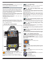
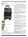
INSTRUCTION MANUAL FOR ARC WELDING MACHINE
IMPORTANT: BEFORE STARTING THE EQUIPMENT,
READ THE CONTENTS OF THIS MANUAL, WHICH MUST
BE STORED IN A PLACE FAMILIAR TO ALL USERS FOR
THE ENTIRE OPERATIVE LIFE-SPAN OF THE MACHINE.
THIS EQUIPMENT MUST BE USED SOLELY FOR WELDING OPERATIONS.
1 SAFETY PRECAUTIONS
WELDING AND ARC CUTTING CAN BE
HARMFUL TO YOURSELF AND OTHERS.
The user must therefore be educated against the hazards, summarized below, deriving from welding
operations. For more detailed information, order the manual
code 3.300.758
ELECTRIC SHOCK - May be fatal.
· Install and earth the welding machine according to
the applicable regulations.
· Do not touch live electrical parts or electrodes with
bare skin, gloves or wet clothing.
· Isolate yourselves from both the earth and the workpiece.
· Make sure your working position is safe.
FUMES AND GASES - May be hazardous to your health.
· Keep your head away from fumes.
· Work in the presence of adequate ventilation, and
use ventilators around the arc to prevent gases from
forming in the work area.
ARC RAYS - May injure the eyes and burn the skin.
· Protect your eyes with welding masks fitted with filtered lenses, and protect your body with appropriate safety garments.
· Protect others by installing adequate shields or curtains.
RISK OF FIRE AND BURNS
· Sparks (sprays) may cause fires and burn the skin;
you should therefore make sure there are no flammable materials in the area, and wear appropriate
protective garments.
NOISE
This machine does not directly produce noise exceeding 80dB. The plasma cutting/welding procedure
may produce noise levels beyond said limit; users
must therefore implement all precautions required by law.
PACEMAKERS
· The magnetic fields created by high currents may affect the
operation of pacemakers. Wearers of vital electronic equipment (pacemakers) should consult their physician before
beginning any arc welding, cutting, gouging or spot welding
operations.
EXPLOSIONS
· Do not weld in the vicinity of containers under pressure, or in the presence of explosive dust, gases or
fumes. · All cylinders and pressure regulators used in
welding operations should be handled with care.
ELECTROMAGNETIC COMPATIBILITY
This machine is manufactured in compliance with the
instructions contained in the harmonized standard
EN50199, and must be used solely for professional purposes in an industrial environment. There may be potential difficulties in ensuring electromagnetic compatibility
in non-industrial environments.
IN CASE OF MALFUNCTIONS, REQUEST ASSISTANCE
FROM QUALIFIED PERSONNEL.
2 GENERAL DESCRIPTIONS
2.1 SPECIFICATIONS
This welding machine is a constant current power source
built using INVERTER technology, designed to weld covered
electrodes (not including cellulosic) and for TIG procedures,
with contact starting and high frequency.
IT MUST NOT BE USED TO DEFROST PIPES.
2.2
EXPLANATION OF THE TECHNICAL SPECIFICATIONS LISTED ON THE MACHINE PLATE.
N°.
Serial number, which must be indicated on any
type of request regarding the welding machine.
Single-phase static transformer-rectifier frequency
converter.
Drooping-characteristic.
SMAW Suitable for welding with covered electrodes.
TIG
Suitable for TIG welding.
U0.
Secondary open-circuit voltage
X.
Duty cycle percentage. % of 10 minutes during
which the welding machine may run at a certain
current without overheating.
I2.
Welding current
U2.
Secondary voltage with current I2
U1.
Rated supply voltage
The machine has an automatic supply voltage
selector.
1~ 50/60Hz 50- or 60-Hz single-phase power supply
I1 max. This is the maximum value of the absorbed current.
I1 eff. This is the maximum value of the actual current
absorbed, considering the duty cycle.
IP23C Protection grade of the housing, approving the
equipment as suitable for use outdoors in the rain.
C: The additional letter C means that the equipment
is protected against access to the live parts of the
power circuit by a tool (diameter 2.5 mm ).
S
Suitable for hazardous environments.
NOTES: The welding machine has also been designed for
use in environments with a pollution rating of 3.
(See IEC 664).
2.3 DESCRIPTION OF PROTECTIVE DEVICES
2.3.1. Thermal protection
This machine is protected by a thermostat, which prevents
the machine from operating if the allowable temperatures are
exceeded. Under these conditions the fan keeps running
and the LED G lights.
NOTE: If upon starting the supply voltage is below 170V, the
LEDs light, the fan is powered but the machine does not deliver current
5
2.3.2 Motor-driven generators
These must have a power equal to or greater than 6KVA, and
must not deliver a voltage greater than 260V.
3 INSTALLATION
MMA F - LED. MMA welding
This machine can weld all types of covered electrodes*
except for cellulosic.
The welding current is adjusted using the knob H.
TIG
Make sure that the supply voltage matches the voltage indicated on the specifications plate of the welding machine.
When mounting a plug, make sure it has an adequate capacity, and that the yellow/green conductor of the power supply cable is connected to the earth pin.
The capacity of the overload cutout switch or fuses installed
in series with the power supply must be equivalent to the
absorbed current I1 of the machine.
WARNING! Extension cords of up to 30m must have a
cross-section of at least 2.5 mm2.
3.1 START-UP
E - LED. 2-stage TIG welding (manual). Start
without high frequency.
To light the arc, press the torch trigger and touch the tungsten electrode to the workpiece, then lift it. This move must
be quick and decisive.
After starting, the current reaches the value set using knob
H.When the trigger is released, the current begins to drop
over the "slope down" time previously set using knob M,
until it returns to zero.
In this position, you may connect the pedal control accessory ART. 193,
TIG
Only skilled personnel should install the machine. All connections must be carried out according to current regulations, and in full observance of safety laws (regulation CEI
26-10 - CENELEC HD 427).
3.2 DESCRIPTION OF THE EQUIPMENT
D - LED. 4-stage TIG welding (automatic). Start
without high frequency.
This program differs from the previous one in that the arc is both
started and shut off by pressing and releasing the torch trigger
TIG
C - LED. 2-stage TIG welding (manual). Start
with high frequency.
To light the arc, press the torch trigger: a high voltage/frequency pilot spark will light the arc.
The operating logic is the same as described for the LED E.
In this position, you may connect the pedal control accessory ART. 193,
TIG
H
G
F
E
D
C
B
A
M
L
95
75
50
MMA
70
90
50
115
I
115
TIG
130 135
25 25
MMA
5
3
2
0
4
5
6
7
A TIG
10
8
9
10
G - LED - THERMAL PROTECTION
Lights when the operator exceeds the duty cycle or percentage intermittence admissible for the machine, and simultaneously blocks the current output.
NOTE: In this condition the fan continues cooling the
power source.
140
150
10
TIG
B - LED. 4- stage TIG welding (automatic). Start
with high frequency.
This program differs from the previous one in that the arc is both
started and shut off by pressing and releasing the torch trigger
5
1
15
20
25
30
POWER TIG
1540 DC HF
®
95
75
50
70
50
115
10
P
Q
4
10
5
1
A - Procedure and mode selector switch
This push-button selects the welding procedure
(MMA or TIG) and mode.
The selection changes each time the button is pressed.
The LEDs light alongside the various symbols to display your
choice.
6
MMA
5
3
2
0
115
H - KNOB
Adjusts the welding current.
130 135
25 25
O
90
5
15
6
140
TIG 150
A
M - KNOB
7
8 Slope down. This is the time in which the current
9
10 reaches the minimum value and the arc shuts off.
(0-10 sec.)
20
25
30
L - KNOB
Post gas. Adjusts the time gas flows after welding
ends. (0-30 sec.)
I - 10-PIN CONNECTOR
The following remote controls are connected to
this connector:
a) foot control
b) torch with start button
c) torch with up/down, etc…
O - 1/4 GAS FITTING
This is where the gas hose of the TIG welding torch is
to be connected.
1~
MMA
f1
f2
POWER TIG
1540 DC HF
TIG
Art.271
0
IP 23C
IEC 60974-1
EN 50199
S
I
V
Nº
®
S
Via A.Costa, 24
40057-Cadriano-Bologna-Italy
MADE IN ITALY
size and length of the welding cables are compatible with the
current used.
3.4
- This welding machine is suitable for welding all types of
electrodes, with the exception of cellulosic (AWS 6010)*.
- Make sure that the switch S is in position 0, then connect
the welding cables, observing the polarity required by the
manufacturer of the electrodes you will be using; also connect the clamp of the ground cable to the workpiece, as
close to the weld as possible, making sure that there is good
electrical contact.
- Do NOT touch the torch or electrode clamp simultaneously with the earth clamp.
- Turn the machine on using the switch S.
- Select the MMA procedure by pressing the button A:
LED F lit.
- Adjust the current based on the diameter of the electrode,
the welding position and the type of joint to be made.
- Always remember to shut off the machine and remove
the electrode from the clamp after welding.
3.5
R
P - Negative output terminal (-)
Q -Positive output terminal (+)
MMA WELDING (MANUAL METAL ARC)
TIG WELDING
This welding machine is suitable for welding stainless steel,
iron, or copper using the TIG procedure.
Connect the earth cable connector to the positive pole (+) of
the welding machine, and the clamp to the workpiece as
close as possible to the welding point, making sure there is
good electrical contact.
Connect the power connector of the TIG torch to the negative pole (-) of the welding machine.
Connect the torch connector to the welding machine connector I.
Connect the torch gas hose fitting to the fitting O on the
machine, and the gas hose from the cylinder pressure regulator to the gas fitting R on the rear panel.
Turn on the machine.
Do not touch live parts and output terminals while the machine is powered.
The first time the machine is switched on, select the mode
using the button A and the welding current using the knob H.
The flow of inert gas must be set to a value (in liters per minute) approximately 6 times the diameter of the electrode.
4 REMOTE CONTROLS
0
S - switch
Turns the machine on and off
I
R - gas intake fitting
3.3.
GENERAL NOTES
Before using this welding machine, carefully read the standards CEI 26/9 - CENELEC HD 407 and CEI 26.11 - CENELEC HD 433. Also make sure the insulation of the cables,
electrode clamps, sockets and plugs are intact, and that the
The following remote controls may be connected to adjust
the welding current for this welding machine:
Art. 193 Foot control (used in TIG welding)
Art (1266) TIG UP/DOWN Torch.
Art 1192+Art 187 (used in MMA welding)
ART. 1180 Connection to simultaneously connect the torch
and the pedal control.
ART. 193 may be used in any TIG welding mode with this
accessory.
Remote controls that include a potentiometer regulate
the welding current from the minimum to the maximum
current set via the knob H.
Remote controls with UP/DOWN logic regulate the welding current from the minimum to the maximum.
7