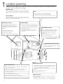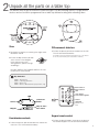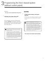
1
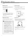
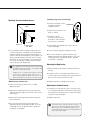
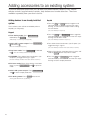
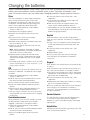
Easy Fit Siren-Based Alarm
system (EF-BX)
Installation · Programming · Operating
Keep this manual safe for reference and future maintenance
Introduction
Contents
Thank you for choosing the Yale Wireless Alarm System.
This simple to install system has been designed with the
user in mind.
Contents
All the components are self contained and no connections
are needed between the units. There is no need to
damage the home decor, lift carpets or run cables.
You can install up to 20 devices in this system. As well as
extra door/window contacts, PIRs and smoke detectors,
you can add keyfob remote controls and keypads for
added control convenience.
There is no need to wire into the mains supply or seek
the services of a qualified electrician. All components are
powered by battery (all batteries included).
Batteries will operate for 2 years or more before they need
changing. Regular testing and battery changes (when
notified by the system) will ensure reliability and peace of
mind.
Each part of the system is ‘tamper’ protected. Any
unauthorised tampering with the system will result in an
alarm. This feature can be turned off by the user when a
battery change is required.
The system has a fixed 20 second entry/exit time when
use with a Keypad. This feature allows you time to leave
the home when arming the system. Upon entering, the
feature allows time to disarm the system without causing
an alarm. Please note there are no countdown when using
a Keyfob to arm or disarm. When the siren is triggered, it
will sounds for 10 minutes.
1 Location planning 2
2 Unpacking the system 3
3 Programming the system 5
4 Mounting alarm devices6
5 Using the system 8
Adding accessories 10
Changing the batteries
11
Specifications 13
Trouble shooting 14
Recommended Installation Sequence
We recommend you follow the easy start sequence,
headings numbered 1-5.
Display extreme caution when using ladders or steps,
please follow manufacturer instructions. Be careful when
using hand and power tools and follow the manufacturers’
guidelines when using them. Take care that the correct
tools are used. Wear goggles or protective clothing where
required.
The external Siren is extremely loud, please ensure you
replace the cover and retreat to a safe distance before
testing.
Special Notes on Compatibility:
This alarm system is NOT compatible with SmartHome
Alarm, HSA6000 series and HSA3000 series accessories.
Please note the prefix “EF-” on the front of the part
number to indicate compatibility.
Information and illustrations are subject to change within this
document. Yale reserves the right to alter the specification and
product design at anytime without notice. Yale® is a registered
trademark. © 2012 ASSA ABLOY. All rights reserved.
1
Location planning
Work out the best places to locate the devices for maximum protection. Having chosen the
locations do not mount at this stage.
Operating range
All devices must be within 30 metres of the siren unit and must
not be mounted on or near large metal objects. Avoid obvious
sources of electrical interference such as fridges and microwave
ovens.
Tamper switches
Siren
Choose a position on an external wall where the
siren would be most prominent. Mount as high
as possible, out of easy reach. (Round shaped siren shown)
When mounting devices ensure that any tamper switches close
fully. On uneven surfaces it may be necessary to place packing
behind the switch for reliable operation.
Help button accessory
Smoke detector
The help button provides extra protection
for you and your family. When help is
needed the button can activate your alarm
immediately - even when the system is
disarmed.
• Mount in the middle of the ceiling at the top of
a stairwell, or on the centre of hallway ceilings
where smoke would most likely be detected.
• Do not mount in corners or above cooking
appliances and heaters.
• Install additional detectors if there are closed
doors preventing smoke from reaching
detectors.
• Mount on flat wall surface
• Designed for indoor use only
• Out of reach of children
Door/Window contacts
Use one door/window contact on a door
that is used as the main point of entry and
exit, usually your front door. The other
door/window contact can be used to
protect
another entry point such as a rear door.
• Mount as high as possible.
• Hidden from view while easily accessible.
• Do not aim a PIR at this door or window.
Yale
R
Keyfob remote control accessory
Can be used outside the premises and
kept on your keyring.
Yale
Yale
Yale
1
2
3
4
5
6
7
8
9
0
Keypad remote control
PIR movement detectors
• Mount in a position such that an intruder would normally move
across a PIRs field of view.
• Height should be between 1.9 and 2 metres above floor level.
• Location in a corner will ensure wider room coverage.
• Do not mount a PIR where its field of view will be obstructed e.g.
by curtains, ornaments etc.
• Do not point directly at sources of heat e.g. fires or boilers, and do
not position directly above radiators.
• Avoid mounting a PIR directly facing a window.
• Do not point a PIR at a door protected by a door/window contact.
2
• The keypad should be sited next to the main point of entry/
exit so that the system can be disarmed/armed within 20
seconds of entering/leaving the premises.
• Ensure that the keypad is not visible from the outside of the
premises.
• Mount at chest height for ease of use.
• Designed for indoor use only.
Extend the system
Extend the system in the future to increase your security or as
your needs change.
For example, add extra PIR detectors in bedrooms and extra
door/window contacts (20 devices in total, including keypad).
The easiest way to get to know the system and get it up and running quickly is to get all the
devices and accessories programmed on a table top before locating and mounting them.
Yale
Status
LED
Learn/Test
Button
Siren
Cover
screw
PIR movement detectors
1 Remove the cover by unscrewing the single screw
located on the lid.
2 Ensure the dip switches position
are as shown in the diagram.
If the switches are in the
wrong position, please change
accordingly.
1 Pull out the plastic pull tab on the back of the PIR.
This will activate the batteries.
(A red light can be seen flashing through the lens. This will last
for 30 seconds indicating the component’s initiation. )
NORMAL
DO NOT SWITCH THE POWER SWITCH TO ON
POSITION AT THIS STAGE.
i Dip Switches
DSW 1: Siren Reset
DSW 2: Jamming detection
DSW 3: Not in use
DSW 4: Siren as Master/Slave (On position only)
Panic button A
Yale
LED
Sensor
Yale
2
Unpack all the parts on a table top
Magnet
Learn/Test
button
/
1
2
3
4
5
6
7
8
9
0
Gap no more
than 10mm
Door/window contacts
1 Pull out the plastic pull tab found on the side of the
main unit. This will activate the battery.
Panic button B
LED
Learn button=
Press 8 and 9 together
Disarm
HomeArm
(Button not in
use)
Keypad remote control
1 Pull out the plastic battery saver tab at the back of
the remote keypad. This will activate the batteries.
3
Keyfob remote control accessory
1 Open the battery compartment using a coin
by turning the cover in the direction of the big
Keyfob
remote control accessory
arrow so the cover small arrow is next to round
dot.
Slide off the battery cover, insert the
battery
as shown,
and replace
223A/MN21
Insert CR2032
battery
and replace
cover.
battery cover. Switch to ‘on’.
kaline
iefly
ating
move)
On/Off switch
/
Smoke detector accessory
1 Remove the cover and insert three AA batteries.
2Smoke
The Smoke
detector
will now enter into selfdetector
accessory
calibration mode for 15-20 minutes (Do not
touch
during
time).
will resume
normal
Remove
thethis
cover
andIt insert
the four
AAA
operation
this period.
batteries
asafter
shown.
mper
witch
Learn/Test
Button
LED
Yale
ontact
or as
Learn/Test button
nals
Help button accessory
Help button accessory
Learn/Test
button
Remove the cover by loosening the fixing
Remove
the insert
cover by
the (supplied)
fixing screw
screw and
theloosening
12V battery
as
and
insert
the
CR2032
battery
(supplied)
as
shown. Please ensure you observe battery
shown
(1). Please observe battery polarity.
polarity.
1
Panic/Learn
button
4
7
3
Programming the Siren-based system
(without control panel)
The siren is the heart of the system. All components must be recognised by the siren.
WARNING
The siren is very loud, be prepared! Take care not
to activate the siren tamper switch unnecessarily.
SETTING
2
1
Switch the siren’s power switch to ON
• Set Dip switch 2 for interference detection. Switch
On to enable and Off to disable (recommended
default).
(The LEDs will now flash with one short beep.)
Once powered, the siren will enter learn
mode for 3 hours. All tamper protections
are disabled within this time period. Please
ensure that ALL devices are fitted before
this mode expires.
unit is equipped with the latest type of
i This
radio receiver using FM radio technology. If the
system is armed any criminal attempt to interfere
detector transmissions will trigger an alarm.
If the alarm is frequently triggered by interference
there may be high levels of unusual radio signals
in your area. Some kinds of electronic equipment
can generate this kind of radio interference.
In the unlikely event of you experiencing problems
with interference, it is recommended that you
switch interference detection off.
The system is pre-learnt in the factory and the
i system should recognised all the items (within
this kit) as default.
If the items are not recognised, deleted by
accident or purchased accessories, please press
learnt/action buttons on the accessories (when
the power switch is first turned on and under
learn mode) to learn each one into the system.
Do not press the siren learn button. See Chapter
2 for learn button location. The siren will beep
each time it receives a learnt signal.
Enable/disable Jamming & interference
detection:
3
The system is now ready for wall mounting.
5
4
Mounting alarm devices
Before mounting the keypad and siren ensure that the siren tamper is
disabled.
Mounting the siren
Mounting the Keypad:
Ensure the tamper switch is fully depressed when
the siren is mounted. If there is a gap, pack with a
suitable spacing material.
1 Knock out the fixing holes. Drill holes into the wall
using the fixing holes as a template.
2 Fit wall plugs into the wall and fix back cover with
the screws provided. Fix front of the keypad onto
the back plate.
Spring compressed
firmly against wall
Round
Siren
Base
Wall
Spring Guide
Battery Saver tab
1 Using the large screws and wall plugs provided,
mount on the desired wall through the 4 mounting
holes. If there is a gap between the wall and the
tamper switch mechanism pack with a suitable
spacing material.
Wall Fixing
knockouts x2
2 Fix the siren cover with the securing screw.
Mounting other devices
Mounting the PIR
Find a location where the device is to be mounted,
see section “Location Planning” for suggestions.
1 Open the PIR by via the bottom screw. Knock out
the relevant holes at the base. The center two
knockout holes are for flat wall mounting while the
4 side holes are for corner mounting.
proceeding to mount the devices
i Before
physically, it is useful to check that it is not out of
radio range by doing a simple range test. Please
ensure the system tamper is disabled.
• Keypad: Hold the keypad in the desired location and press the arm button.
(The siren will beep as confirmation.)
• Help button: Hold the device in the desired location and press the emergency
button for 2 seconds.
Wall fixing
knockouts x2
(The siren should respond with a single beep.)
• All other devices: Hold the device in the
desired location and press the learn/test button.
(The siren should respond with a single beep.)
When you are satisfied that the devices work
in your chosen locations, proceed with the
installation as described in the next page.
If the siren does not respond, the location may be
out of range, try alternative locations until reliable
radio contact is obtained.
6
Battery tab
Corner fixing
knockouts x4
2 Drill holes into the wall using the knockout holes on
the base as a template. Secure the base with the
screws provided.
3 Fit the PIR back together and tighten bottom
screw.
Mounting the door/window contact
Frame
Door/Window
Sensor
Yale
Magnet
Sensor
Gap no more
than 10mm
1 Find a location where the door/window contact
is to be mounted. It should be mounted between
the door/window frame and the door/window as
shown at the top of the opening. The magnet is to
go on the door/window while the sensor is to be
placed on the frame. Windows can be protected
in a similar way to doors. Make sure the tamper
switch spring is fully depressed.
gap between the magnet and sensor should
i The
be approximately 10mm when closed (depending
-Mounting using screws and wall plugs
1 Loosen the bottom screw
and open the door/
window contact.
Knockouts
2 Knock out the holes on the
base as shown.
3 Drill holes into the
mounting surface using
the holes in the knockouts
on the base as template.
4 Fit wall plugs (if required) and secure with the
screws provided.
5 Fit sensor back together and tighten screw.
6 Test sensor by pressing the test button and
opening and closing the door/window. The LED
should light when the door/window is opened.
Installation is complete.
Mounting the Help button
upon the actual environment).
1 Break through the knockouts (where the plastic is
thinner).
Simple test to see whether the magnet is in range
of the sensor: hold the magnet and sensor in
place and then pull them apart. If the sensor LED
lights up it implies the two items are within range.
2 Using the holes as a template, drill holes in the
surface and insert wall plugs if fixing into plaster or
brick. Screw the rear case to the wall.
-Mounting using adhesive pads
3 Replace the cover and tighten the screw.
1 Clean the mounting surface with a suitable
degreaser agent.
Mounting the Smoke Detector
2 Remove the protective film from one side of the
adhesive pad and apply to the back of the sensor
and magnet
1 The base has two mounting slots. Using the slots
as a template, drill holes and insert the wall plugs if
fixing to plaster. Screw the rear case to the ceiling
using the screws provided.
3 Remove the remaining protective film and firmly
press into place.
2 Replace the cover.
4 Test sensor by pressing the test button and
opening and closing the door/window. The LED
should light when the door/window is opened.
Installation is complete.
tamper switch will automatically reactivate
i The
after 3 hours (after initial Siren power switch On).
Alternatively you can enable the tamper switch
manually by disarming using your keypad (Disarm
& pincode: default 0000).
7
5
Using the system
Arm and disarm the system and practice using it. Trigger the alarm by arming the system
and opening protected doors/windows and walking past PIRs. Now’s the time to set your pin
code and show the rest of the family how simple it is to use.
The PIRs have a built-in sleep timer to save
Changing your keypad PIN code
of the PIRs for 1 minute, the PIRs will become
‘ready to signal’ and movement will now be
reported. The PIRs will sleep for 1 minute after
reporting.
1 Enter setting mode: Press the Panic button A,
followed by entering the current pincode (factory
default code is 0000).
Any movement detected in sleep time will not be
reported and will extend the sleep period by a
further 1 minute.
2 Press panic button B.
i battery power. If there is no movement in front
Arming the system
Keypad/Keyfob: Press arm
(The siren will beep/flash once. No audible countdown.)
i
• Keypad will arm the system with a 20 seconds exit period. All detectors will be ignored (except for the tamper switches). The system can be
armed when inside the protected area of your
premises.
• Keyfob will arm the system instantly without a
20 second exit delay. Any detector activated
afterwards will trigger an instant alarm. The
system should be armed when outside the
protected area of your premises.
Disarming the system
Keypad: Press disarm followed by your pincode.
Keyfob: Press disarm.
(The siren will beep twice and flash.)
i
• Keypad: If the system has been armed with a
keypad there will be a 20 second entry period
started when the first detector is activated
(usually a window/door contact on the main
point of entry). During this entry period all
detectors will be ignored.
• If the system is not disarmed before the entry
period expires, the alarm will be activated.
• The system does not have an audible
countdown during the entry period, however
the siren will beep once when the first detector
is triggered.
• Keyfob: If the system has been armed with a
keyfob there will be no 20 second entry period
and any detector activation will give an instant
alarm.
• The system should be disarmed from outside
the protected area of your premises.
Stopping the Siren
Keypad: Press disarm followed by your pincode.
Keyfob: Press disarm.
8
(The siren will be silenced and then beep twice and flash.)
(The LED will now flash continuously.)
3 Enter new 4-digit pincode.
4 Press Arm button to confirm.
5 Exit setting mode: Press disarm twice to quit the
changing code process. Or wait for 5 minutes for
the keypad to quit test mode automatically.
(The LED will now stop flashing.)
the PIN code doesn’t change, repeat the
i • Ifabove
procedure quickly without gaps.
Tamper alarm warning
If any device tamper switches are disturbed a
tamper alarm will be activated with the siren
sounding and the strobe flashing. The alarm can be
silenced as described in “Stopping the Siren”.
i
If there is a persistent siren tamper fault then a
series of 5 pips and flashes will be given when
the system is armed, then the siren should be
checked for any mounting problems and if the
siren lid is secure. Use packing material for
uneven wall surface.
Previous alarm warning
Should there be an alarm that was triggered and
expired (while the user was away), the siren will
sound and flash for 3 seconds after disarming (user
returning home).
* Warning: should this happen the intruder could still
be in the premises.
My PIN code:
(write your pincode here so you don’t forget it)
Using the help button
Panic alarm using keypad
Activate: Press and hold panic button for 3
seconds, the LED will light briefly and the siren will
be activated.
Activate: Press and hold Panic button A & Panic
button B together.
Silence: Press disarm follows by pincode.
Silence: Press and hold panic button for 10
seconds, the LED will light briefly and the siren will
be silenced.
i
Panic alarm using keyfob
Activate: Press and hold Panic button.
Please note that silencing the alarm with the
help button does not disarm the system. If the
alarm is armed prior to activation, the system
will re-arm after being silenced with the help
button.
Using the smoke detector
The smoke detector will indicate a fire by sounding
its built-in siren, lighting the LED and activating the
external siren and strobe.
-Smoke detection
When smoke is detected the device will activate for
a minimum of 10 seconds with a two tone alarm and
flashing LED for a local fire alarm. The detector will
also activate the external siren and strobe.
• Pressing the test button when in an alarm
condition will silence the alarm for 10 minutes, it
will automatically resume smoke detection again
after this period.
• If the smoke density is still over the alarm
threshold, then the smoke detector will remain in
an alarm condition and it will repeat the local fire
alarm and activate the external siren and strobe
again.
-Testing
Smoke detector testing should be done on a regular
monthly basis. Pressing the test button will make
the LED flash, the audible sounder chime and will
send a radio test signal to the siren when the button
is released. If nothing happens after pressing the
test button then change the batteries.
-Recalibration
The smoke detector might need recalibrating after
time to ensure it is working at its optimum. This is
done by pressing and holding in the test button until
the LED flashes and it beeps after 10 seconds. The
detector will then start its self-calibration routine.
Silence: Press disarm.
Keypad Modes:
Table 1
Entering setting mode:
Press Panic button A followed by pincode (factory
default is 0000). You can now select different function.
(The LED on the keypad will start flahsing)
Function setting:
Press Panic button A , followed by one of the
following number key:
1 Send learning/testing signal (same as 8+9)
2 Disable Siren tamper
3 Enable Siren tamper
4 Enter learn mode (not suitable for first time set-up)
5 Exit learn mode
7 Keypad to work with control panel based sysem.
8 Keypad to work with siren based system.
Exiting setting mode:
Press disarm twice.
(The LED will now stop flashing. If not, press disarm twice
again)
KeyFob Modes:
Table 2
• Sending learn signal
Press any key except the emergency button.
• Siren tamper (Enable)
Press and hold down Arm and emergency for 5
seconds.
• Siren tamper (Disable)
Press and hold down Arm and Home for 5
seconds.
• Learn mode (Enter)
Press and hold down Home and emergency for 5
seconds.
• Learn mode (Exit)
Press and hold down disarm for 5 seconds.
9
Adding accessories to an existing system
To provide additional protection you can add extra door/window contacts, PIRs, keyfob
remote controls, keypad remote controls, help buttons and smoke detectors. These are
available separately from your local stockist.
Adding devices to an already installed
system
The installed system will be controlled by either a
keyfob(s) or a keypad(s).
Keypad
1 Press the Arm and Home buttons together and
continuously for 5 seconds until the LED stops
flashing, to switch off the tamper while installing
the new device.
(The siren will beep in response.)
1 Enter Setting mode: Press Panic button A
followed by the pincode
(Indicated by a continuously flashing LED.)
2 Press the Home and Emergency buttons together
and continuously for 5 seconds until the LED stops
flashing to enter learn mode.
(The siren will beep and flash in response.)
2 Switch OFF system tamper: Press Panic button
A followed by 2
(The siren will beep in response.)
3 Press device learn/test buttons (see Chapter 3) to
trigger learning-in signals.
3 Enter learn mode: Press Panic button A followed
by 4 . (The siren will beep and flash in response.)
4 When all the devices have been learnt-in press and
hold the Disarm button to quit learn mode.
4 LEARNING: Press device learn/test buttons (see
Chapter 3) to trigger learning-in signals.
5 Press the Arm and Emergency buttons together
and continuously for 5 seconds until the LED stops
flashing to rearm tamper protection.
(The siren will beep and flash when each device is learnt in.)
5 Exit learn mode: When all the devices have been
learnt in, press Panic button A and 5 to quit learn
mode.
6 Switch ON system tamper: Press Panic button A
and 3 to rearm tamper protection.
7 Exit Setting mode: Press Disarm twice to exit.
(The keypad LED will now stop flashing.)
10
Keyfob
(The siren will beep and flash when each device is learnt in.)
Changing the batteries
Always use alkaline batteries or the correct type of coin cells as replacements because any other
battery can cause problems with the operation of the system. Typical life of batteries is two
years. Ensure the correct steps are taken when changing batteries in tamper protected devices.
Siren
The siren will produce a series of pips and flashes
when arming and disarming the system when
the batteries start getting low. After the warning
the batteries will have about enough energy for 1
month’s normal operation before exhaustion.
1 Switch off tamper protection as described in
section 5, table 1 & 2.
The batteries are changed as follows:
2 Remove the siren lid and switch off the siren
power.
3 Unscrew the four screws on the battery
compartment lid and remove.
4 Remove the four batteries and replace them with
four fresh alkaline “D” cells.
5 Switch on siren power and check that the siren
beeps and flashes.
Note After the batteries have been changed
and system powered on, the tamper will become
inactive for 3 hours to allow fitting.
6 Replace battery compartment lid and screws
and reattach siren lid. Tamper protection would
automatically enabled when the 3 hours period
expired.
• Disarming under tamper condition causes the LED
to flash sequentially for 2 cycles instead of 1 cycle
under normal condition.
PIR
When the battery is low the LED will flash when any
movement is detected. The batteries are changed
as follows:
1 Switch off tamper protection as described in
section 5, table 1 & 2.
2 Loosen the case screw and remove PIR sensor
from base to reveal three AAA batteries.
3 Press the learn button to drain residue power.
4 Insert new alkaline batteries observing correct
polarity.
5 Refit sensor on base and tighten bottom case
screw. Switch tamper protection back on.
• PIR case tamper conditions are also indicated by
a flashing LED, check the tamper before changing
the batteries.
Door/window sensor
When the battery is low the LED will lights up when
the door/window is opened or when tamper is
triggered. The battery is changed as follows:
1 Switch off tamper protection as described in
section 5, table 1 & 2.
2 Loosen the case screw and remove door/window
sensor from base to reveal battery.
3 Using a screwdriver gently lever out the old
battery.
4 Insert new CR2032 coin cell with the + side
uppermost.
5 Press battery into holder firmly with finger and
thumb until a click is heard.
6 Refit sensor on base and tighten bottom case
screw. Switch tamper protection back on.
• Door/window sensor case tamper conditions are
also indicated by a flashing LED, check the tamper
before changing the battery.
Keyfob
When the battery is low the LED will glow dimly
when any key is pressed. The battery is changed as
follows:
1 Using a coin turn the battery cover anticlockwise
to the unlocked position and remove cover and
battery.
2 Insert new CR2032 coin cell with the + side
uppermost.
3 Replace battery cover.
4 Press any key and check that the LED lights.
If the LED lights the new battery installation is
successful.
Keypad
Note: Disable siren tamper before proceeding (Page
9, table 1)
When the battery is low the LED will flash when any
key is pressed. The battery is changed as follows:
1 Unscrew the two keypad case screws and remove
keypad back to reveal battery. Using a screwdriver
gently lever out the old battery.
2 Insert new CR2032 coin cell with the + side
uppermost.
3 Slide battery into holder. Please note the + contact
pin must stay above the battery.
4 Press a number key and check that the LED lights.
If the LED lights the new battery installation is
successful, screw keypad back on and the battery
change is complete.
Smoke Detector
The LED will flash and the sounder will beep every
30 seconds to signal low battery. Change the
batteries as soon as possible with fresh AA alkaline
replacements.
Help Button
Remove the cover by loosening the fixing screw and
insert a new CR2032 battery.
11
ASSA ABLOY Ltd.
School Street, Willenhall
West Midlands
England, WV13 3PW
ASSA ABLOY Ltd.
School Street
Willenhall
West Midlands
England
WV13 3PW
Model:
Model:
HSA3400
EF-KIT1
HSA6010
HSA3400
EF-KIT2
HSA3020
HSA6020
EF-KIT3
HSA3020
HSA3060
EF-PC
HSA6021
HSA3060
HSA3010
EF-DC
HSA6050
HSA3010
EF-PIR
HSA3050
HSA6060
EF-PETPIR
HSA3050
HSA3045
HSA6080
EF-KF
HSA3045
EF-KP
HSA6090
HSA3080
HSA3080
EF-BX
HSA6091
HSA3030
EF-SD
HSA3030
HSA3045
HSA3070
EF-PB
HSA3070
EF-PANEL
EN 300 220-1 / V2.3.1 (2010)
EN 300 220-2 / V2.3.1 (2010)
EN 301 489 -1 / V1.8.1 (2008)
EN 301 489-3 / V 1.4.1 (2002)
EN 60 950-1 / 2006 + A11 : 2009 + A1: 2010 + A12:2011
John Ward
Director
Date:
03/09/12
16/11/06
On behalf of ASSA ABLOY Ltd.
12
17
17
Specifications
All devices
Environmental conditions
-10°C to 40°C, relative humidity
70% non-condensing for all units
except the external siren. Siren:
-20°C to 50°C, relative humidity
95% non-condensing
Radio operational range
30m in a typical domestic
installation, range can vary
depending on building construction,
device positions and RF
environment
Housings ABS/polycarbonate
Siren
Siren output 104dBA sound
pressure @ 1m minimum
Radio 868MHz FM
Power supply 6V, 4 x D alkaline
cells. 2.5 years typical service life
Passive infra red (PIR)
Detector
Alarm processing Microprocessor
controlled dual edge sequential
pulse count with pulse length
discrimination
Radio 868MHz FM
Power supply 4.5V, 3 x AAA
alkaline cells. 2 years typical
domestic service life without
supervision.
Movement detection range 12m,
110°
Help button
Radio 868MHz FM
Power supply 3V, CR2032 lithium
coin cell. 3 years typical domestic
service life
Door/window contact
Radio 868MHz FM
Power supply 3V, CR2032 lithium
coin cell. 2 years typical domestic
service life without supervision.
Smoke detector
Radio 868MHz FM
Power supply 4.5V, 3 x AA alkaline
cells. 3 years typical domestic
service life
Tested to EN54
Keyfob remote control
Radio 868MHz FM
Power supply 3V, CR2032 lithium
coin cell. 3 years typical domestic
service life
Keypad remote control
Radio 868MHz FM
Power supply3V, CR2032 lithium
coin cell. 3 years typical domestic
service life
13
Troubleshooting
For online assistance, please visit:
Siren
Siren does not respond to keypad
• Keypad low battery or bad connection. Check
battery connections and polarity, if OK replace
battery.
• Siren batteries are completely exhausted. Check
siren batteries by removing siren cover, if there is
no tamper alarm when removed, replace batteries
with new alkaline equivalents.
• Keypad not learnt-in. If siren produces a tamper
alarm when the cover is removed, and keypad is
OK, learn-in the keypad.
• Siren could be out of radio range.
Siren produces a 3 second alarm when
disarmed
• There has been a previous alarm and there might
be an intruder still in the premises.
Siren produces a series of pips when armed or
disarmed
• The siren has low batteries. Check that the
siren produces a series of pips when arming
and disarming, indicating low batteries. Change
batteries with new alkaline replacements.
• The siren tamper switch has been disturbed.
Check that the siren produces a series of pips only
when arming, indicating a tamper condition. Check
that the siren cover is firmly secured and the
tamper switch plunger is in contact with the wall. If
not use suitable packing material to fill gap.
Siren produces an interrupted tone when
sounding an alarm
• The siren has low batteries. Change batteries with
new alkaline replacements.
Keypad
The keypad LED will not light when the arm key
is pressed
• Battery is completely exhausted. Change battery
with CR2032 coin cell replacement.
The keypad LED will not work after battery
changes
• Battery is completely exhausted. Change battery
with CR2032 coin cell replacement.
• Battery been inserted incorrectly and the + battery
contact pin had been pressed to the side. Check the
battery compartment and ensure the + battery pin
stays above the battery.
14
The siren will not respond to the disarm user
code
• Ensure that the keypad mode is correct by entering
test mode and pressing button “A” then “8”.
www.Yale.co.uk
Forgotten user PIN code
• See “Keypad reset procedure” on the next page.
PIR
PIR does not respond to movement
The PIRs have a built-in sleep timer to save
i battery power. If there is no movement in front
of the PIRs for 1 minute, the PIRs will become
‘ready to signal’ and movement will now be
reported. The PIRs will sleep for 1 minute after
reporting.
Any movement detected in sleep time will not be
reported and will extend the sleep period by a
further 1 minute.
To test, arm system and vacate protected
room for at least 1.5 minutes before testing.
PIR is slow to respond
• This is normal, the PIR has sophisticated false
alarm filtering that will filter out random fluctuations
and responds to genuine movement across field of
view, it is less sensitive walking directly towards it.
PIR gives false alarms
• Check pets have no access to protected area.
• Check that PIR is not pointed at sources of heat or
moving objects, e.g. fluttering curtains.
• Check that PIR is not mounted above convector
heaters or pointing directly at windows.
PIR LED flashes
• Batteries are low or the tamper switch is disturbed.
Check that the tamper switch spring is making
contact with base. If the tamper switch is OK,
change batteries with new alkaline replacements.
PIR does not respond to movement after test/
learn button has be pressed
• Batteries are completely exhausted. Change
batteries with new alkaline replacements, LED will
flash for 30 seconds while components initialise.
Door contact
Door contact LED lights up
• Batteries are low or the tamper switch is disturbed.
Check that the tamper switch spring is making
contact with the mounting surface. If the tamper
switch is OK, change batteries with new alkaline
replacements.
Door contact does not respond to door
opening after test/learn button has been
pressed
• Batteries are completely exhausted. Change
batteries with new alkaline replacements
• The magnet is too far away from the door contact.
Check that the gap between door contact and
magnet is not greater than 10mm.
Siren reset procedure
• Switch the power switch to Off position. Press
the learn buttons a few times to drain any residual
power.
• Switch DipSwitch 1 to On position
• Switch the power switch to On position. Wait 5
seconds. Siren LED will flash 1 cycle.
• Switch DipSwitch 1 to Off position
The siren is now reset and all learnt devices are
cleared from memory. See chapter 3 for initial setup. Please be reminded that all devices will need
to be learnt in at this point. One by one, press the
learnt button on device to learnt in.
Keypad reset procedure
The keypad is tamper protected. Please ensure the
siren tamper is disabled before you open the keypad
cover. See Page 9, table 1 for siren tamper disable
procedure.
• Open cover and remove battery. Reinsert with
the number “3” key pressed (taking care 3 is held
down).
• The keypad will go back to the “0000” keypad
code.
• The keypad will now have to be re-learnt into the
Siren, see chapter 3.
15
All devices
EMC
Power supply 3 x AAA alkaline cells. 3
Passive infra red (PIR) detector
years typical domestic service life
All devices
Passive
infra red (PIR) detector
Alarm processing Microprocessor
dual edge sequential pulse
EMC controlled
Tested to ETS 300 683
count with pulse length discrimination
Radio Components tested to EN
Tested
to433.92MHz
ETS 300 683
Radio
AM transmitter
300 220-1
Radio
Components
EN
Power
supply 4.5V,tested
3 x AAtoalkaline
cells.
300 220-1
3 years typical domestic service life, 1Environmental conditions
minute sleep timer
conditions
-10°Cistoguaranteed
40°C, relative
humidity againstEnvironmental
Movement
detection range 15m, 110°
This product
for consumers
faulty workmanship,
to purchase
40°C, relative humidity
70% and
non-condensing
for all of
units
materials
function for a period
2 years from the-10°C
date of
providing
thethe
fullexternal
installation
and maintenance
are followed. forcontact
70% non-condensing
all units
Door/window
except
siren.
Siren: -20°Cinstructions
Please
keep your
proofhumidity
of purchase
safe,
this must
be submitted
when siren. Siren: -20°C
except
the external
to 50°C,
relative
95%
nonmaking a claim under this guarantee.
Radio Microprocessor controlled
to 50°C, relative humidity 95% noncondensing
433.92MHz AM transmitter
condensing
Please note that it is a condition of this guarantee
that
your
Yale3V, 2 x AAA alkaline cells. 3
Power
supply
Radio operational range
product:
years typical domestic service life
Radio operational range
30m in a typical domestic
30mSmoke
in a typical
domestic
installation, range can vary depending
• Hasbeencorrectlyinstalledandmaintainedinaccordancewiththe
detector
Yale
installation
and maintenance
instructions installation,
provided to you
at can vary depending
range
on building
construction,
device
the time of purchase.
Radioconstruction,
Microprocessor
controlled
on building
device
positions and RF environment
• Hasnotbeenmodifiedordamagedinanyway.
433.92MHz AM transmitter
positions and RF environment
• Hasnotbeensubjectedtounauthorizedrepairs.
Power supply 6V, 4 x AAA alkaline cells. 3
Housings ABS/polycarbonate
typical domestic service life
Housingsyears
ABS/polycarbonate
2 Year Guarantee
Statement
Yale are responsible under this guarantee for repairing the product or
Siren
replacing the product as we deem necessary. If there isKeyfob
fault with remote
the
control
Siren
product,
please104dBA
contact sound
Customer
Services
Siren output
pressure
@ on 01902 364647, who
willgiveyouthenameofanexpertandconfirmwhatyouneedtodo
Radio104dBA
Microprocessor
controlled
1m minimum
Siren output
sound pressure
@
to make
claim under AM
this guarantee.
433.92MHz AM transmitter
Radioa433.92MHz
super heterodyne
1m minimum
Power supplyAM
12V,
23A/MN21
alkaline
receiver with jamming detection
Radio 433.92MHz
super
heterodyne
Please
do
not
carry
out
any
repairs
without
our
authority
by using
an detection
miniature
"lighter"
battery. 3 years
Power supply 6V, 4 x D alkaline cells. 3
receiveror
with
jamming
unauthorised
expert.
Any repairs
out
without
typical
service
life 3
years typical
service
life or other works carried
Power supply
6V,domestic
4 our
x D alkaline
cells.
authorizationorbyusinganunauthorizedexpertwillnotbecovered
years typical
service
life control
Keypad
remote
under this guarantee.
Radio Microprocessor controlled
This guarantee is non transferrable and applies to products
purchasedAM transmitter
433.92MHz
in the United Kingdom only. This guarantee does not apply to normal
wear and tear. This does not affect your statutory rights. A full copy of
this guarantee is available upon request by writing to Yale UK, School
Street, Willenhall, West Midlands. WV13 3PW or by visiting our website
www.yale.co.uk.
Alarm processing
Microprocessor
Help button
controlled dual edge sequential pulse
EMCpulse
Tested
to EN
300 220-1 and ETS
count with
length
discrimination
300 683 AM transmitter
Radio 433.92MHz
Environmental
-10°C to
Power supply
4.5V, 3 x AAconditions
alkaline cells.
humidity
70%
3 years40°C,
typicalrelative
domestic
service
life,non1minute condensing
sleep timer
Radio
operational
Movement
detection
range 15m,range
110° 30m in a
typical domestic installation. Can vary
depending on building construction and
Door/window
contact
RF environment
Radio Microprocessor controlled
Radio Microprocessor controlled
433.92MHz AM transmitter
433.92MHz AM transmitter
Power supply 12V 23A/MN21 alkaline
Power supply 3V, 2 x AAA alkaline cells. 3
miniature ‘lighter battery’. 3 years
years typical domestic service life
typical domestic service life
Smoke detector
Power supply 3 x A
years typical dom
Help button
EMC Tested to EN
300 683
Environmental c
40°C, relative hum
condensing
Radio operation
typical domestic
depending on bu
RF environment
Radio Microproc
433.92MHz AM t
Power supply 12
miniature ‘lighter
typical domestic
Radio Microprocessor controlled
433.92MHz AM transmitter
Power supply 6V, 4 x AAA alkaline cells. 3
years typical domestic service life
Keyfob remote control
Radio Microprocessor controlled
433.92MHz AM transmitter
Power supply 12V, 23A/MN21 alkaline
miniature "lighter" battery. 3 years
typical domestic service life
Keypad remote control
Radio Microprocessor controlled
433.92MHz AM transmitter
NoPb
18
18
16
WEEE
Note: Waste electrical products and
batteries should not be disposed of with
household waste. Please recycle where
facilities exist. Check with your local
authority or retailer for recycling advice.
0560
E1 09/12
THE YALE BRAND, with its unparalleled global reach and
range of products, reassures more people in more countries
than any other consumer locking solution.
THE ASSA ABLOY GROUP is the world’s leading
manufacturer and supplier of locking solutions, dedicated
to satisfying end-user needs for security, safety and
convenience.
056