1
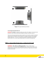
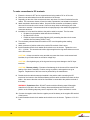
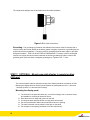
Transportation Products Cooper Bussmann Inverter 1000W / 1800W INSTALLATION GUIDE About Cooper Bussmann In a worldwide transportation marketplace Cooper Bussmann is your leading source for safe and reliable electrical power and machine control solutions. We’re experts on the effects of temperature, vibration, high moisture, harsh chemicals and transient power fluctuations. We know vehicle power and control systems from the smallest to the largest platforms, and will partner with you to develop reliable products and systems. With combined industry history and experience reaching back more than 90 years, the engineering strength and proven track record of the Cooper Bussmann®, Sure Power and Martek Power brands provide you the ability to accelerate product development in “smart” systems and create innovative, industry-leading solutions. These solutions range from straightforward catalog products to next generation systems that will create efficiencies not yet realized. The Cooper Bussmann mission is to respond completely and uniquely to OEM requirements for vehicle electronic products and control solutions, providing cost reduction and customization. We are committed to continuous new product development and offer you a competitive advantage through R&D expertise and a technology portfolio that minimizes excessive tooling and time required to produce OEM-specific solutions. Cooper Bussmann, a division of Cooper Industries, has a global manufacturing footprint. Our facilities are ISO 9000-2001 and TS16949 certified to meet the highest quality and environmental standards. Warranty Terms Seller provides products as-is and makes no representations or warranties, express or implied, statutory or otherwise, regarding the products, their fitness for any particular purpose, their merchantability, their quality, their non-infringement, or otherwise. Contact Information Phone: 800.845.6269 Fax: 503.692.9091 www.cooperbussmann.com 2 Important Safety Instructions WARNING: Limitations on Use – The Cooper Bussmann Inverter is not to be connected to life support devices. CAUTION: Risk of injury – To avoid risk of injury, use only 12Vdc, lead-acid, rechargeable batteries (i.e. GEL, AGM, and Flooded). Other types of batteries may burst, resulting in personal injury and/or damage. Do not expose inverter to rain, snow, spray, or water. Do not cover/obstruct ventilation systems. Use wire in good condition and of appropriate ratings. Attachments not recommended by Cooper Bussmann may be damaging to inverter. Do not use inverter after being dropped, hit, or damaged. Do not disassemble the inverter. Risk of shock, fire, and void of warranty may result. Remove all AC and DC connections before maintenance, cleaning, or circuit work. Provide inverter an equipment-grounding conductor connected to AC input ground. Insure cables are routed properly, secured and protected from chaffing. WARNING: Explosion hazard – Working with batteries can be very dangerous. It is crucial to follow all steps completely while servicing the unit. It is possible for the inverter to produce arcs and/or sparks, do not install or use inverter near flammable materials (i.e. gaspowered machines, fuel tanks, or any components connected to a fuel supply). Follow any instructions from the battery manufacturer being used. Personal Precautions When Working with Batteries WARNING: risk of electrical shock, burn from high short-circuit current, fire or explosion from vented gases. 3 Follow the instructions and precautions from the battery manufacturer (i.e. cap removal, or charging rates). Follow battery instructions for water and battery acid levels from the battery manufacturer. Ventilate the area near the batteries as much as possible. Do not smoke or produce flame/spark near engine or batteries. Use caution when handling tools around batteries. Remove all metal items (i.e. rings, bracelets, watches) from person when working with batteries. Work within voice range of other people. Wear eye and clothing protection while working, and avoid touching eyes during installation. Upon battery acid contacting skin or clothing, wash immediately with soap and water. Upon contacting eye(s), flood immediately with running cold water for at least twenty minutes and seek medical attention. DC CONNECTION PRECAUTION(s) – Make only DC output connections or disconnections after setting all unit switches to OFF position and opening AC disconnect(s). It is recommended to review TMC RP 160 and RP 163 which include wiring and selection recommendations. 4 CONTENTS Installation ............................................................................ pg 6 Configuration ........................................................................ pg 24 Specifications ....................................................................... pg 28 5 1. INSTALLATION Chapter 1 offers information as a guide to installing a Cooper Bussmann Inverter/Battery Charger. It will cover the following: Materials list Safety instructions Sample installation tools and materials Installation procedures for mounting and connecting the product ground, AC cabling, DC cabling, and grounding techniques 6 Materials List The Cooper Bussmann Inverter package includes the items listed below: 1 Cooper Bussmann Inverter unit Owner’s / Installation Guide 25 foot RJ11 cable for remote mounting of control panel 2 ea M8x1.25 Nuts with Lock Washer and Flat Washer for Battery Positive and Battery Negative 1ea M6x1.00 Nuts with Lock Washer and Flat Washer for Chassis Ground Connection One Red and one Black Insulating Boot for covering up to 00 AWG Battery Positive and Battery Negative Connections 2ea cable clamps for retention of hardwired AC Input and AC Output 2ea ground lugs for chassis ground connection of hardwired AC input and AC output Figure 1-1 What’s in The Box 7 Safety Instructions WARNING: Shock hazard – All wiring of connectors or otherwise should be done by a technician, electrician, or person with electrical experience. At the beginning of this guide there is a section of warnings and cautions, take note of any precautions concerning the installation. Prior to engaging in any service, all AC and DC power sources need to be disconnected and all AC and DC devices and generators need to be disabled. Follow proper cable routing and strain relief guidelines. Installation Codes Installation codes vary depending on specific industry, location and application of inverter. It is the installer’s responsibility to ensure that all applicable installation requirements are met. 8 Installation Tools and Materials To install the Cooper Bussmann Inverter, the following tools/materials are recommended: Wire strippers Mounting screws or bolts #2 Phillips screwdriver Wrench or socket for DC terminals (1/2 inch or 13mm) AC cable (i.e. 3-prong, standard wall cable), sized appropriately for load/application Wire nuts or crimp connectors for AC wire and appropriate tools DC cable, sized appropriately for load/application Lugs for DC cables to mount on size M8 x 1.25 studs. DC stud terminals and appropriate tools(i.e. crimping tool) Lug for Chassis Ground cable to mount on size M6 x 1.00 stud. DC stud terminal and appropriate tools(i.e. crimping tool) 9 AC and DC disconnects and over-current protective devices STEP 1: Determine an installation type Installation of the inverter will involve many common components, some which are shown below. Figure 1-2 shows some of those components and their relevance with each other in a standard heavy truck or recreational vehicle installation. Figure 1-2 Typical Recreational Vehicle and Fleet Vehicle Installation 10 AC Shore Power – [“shore power” refers to AC input power from a utility grid, generator, or other AC source.] To charge batteries and pass power on to an AC load, a source of nominal 115Vac, 60Hz is needed. This source is predominantly the utility grid (wall power, power company) or an AC generator. In the case of multiple sources, an automatic or manual AC source selector switch can be used. The AC source going into the inverter must have a neutral conductor bonded to ground (i.e. 3-prong wall cable). When the inverter is passing AC power through, it relies on the input being grounded to ensure the power delivered to a sub-panel is bonded. See “AC Output Neutral Bonding” on page 12 for further information on bonding relay operation. *Please note that the grid power source utilized must be branch breaker or branch fuse protected at 30 Amp maximum. Generator – The inverter is capable of handling most generators that produce nominal 115Vac, 60Hz sine wave AC power. The current limit for DC charging is programmable to as little as 2A, therefore a very small generator would be sufficient. AC Disconnect and Over-Current Protection Device – The inverter is required by safety and electrical codes to have AC and DC input/output overcurrent protection (i.e. circuit breakers and/or fuses), as well as disconnect devices. The following are suggested protective measures for each configuration: AC Input: The branch fuse or branch circuit breaker (hard wired) used on the source of the inverter must be rated to a max 30A and must also be approved for use on 115Vac systems. The wire used between the breaker and the inverter needs to be sized accordingly to pass the same amount of current rated for the fuse. AC Output: The fuse or circuit breaker on the output should not be rated any higher than that of the input. The wire between the inverter and the AC output breaker should be rated to carry the amount of current rated for the fuse. Any subsequent wiring from this output breaker to the loads must be sized accordingly for the current being passed to each individual load. 1000 Watt models feature an integrated 15 Amp AC output breaker while 1800 Watt models feature an integrated 20 Amp AC output breaker. Disconnect Devices: Each fuse or breaker system requires a method for disconnecting. If the devices used are circuit breakers, these will serve as the disconnects. If they are fuses, separate AC disconnect switches will be necessary ahead of the fuses; these switches will be a branch circuit with proper current characteristics and rated to 120Vac. AC Distribution Panels – A usual system will incorporate distribution centers ahead of the inverter and between the inverter and the loads (AC load panel). AC source panels will include a main circuit breaker, serving as the over-current protection and the disconnect switch for the AC power supply. AC load panels can utilize an AC output circuit breaker, and breakers for each subsequent load circuit. CAUTION: Equipment damage – Do not connect the output of the inverter to what is known as a “multi-wire branch circuit.” 11 AC Cabling – AC cabling includes but is not limited to all wires/cables between the AC source and the inverter, and all the cabling between the inverter and AC outputs (panels, circuit breakers, and loads). Wiring type and size varies with installation and load. Installation codes will recommend solid or stranded wires, overall size of conductors, and type/temperature ratings of insulation around the wire. Ensure AC breakers and fuses are sized appropriately for current, insulation for voltage, and ambient temperature ratings. Table 1-1 gives examples of wiring sizes based on the breaker rating. Examples are based on use with a 2-conductor-plus-ground (3-prong) cable rated at 75°C. AC Output Neutral Bonding – AC input neutral and output neutral must be isolated from each other. This being noted, the neutral conductor of the inverter AC output circuit (i.e. AC output neutral) is automatically connected to the safety ground during inverter operation. When using an AC utility power source and the inverter is in charging mode, this connection is not present. DC Cabling – DC cabling includes but is not limited to all cables and connectors between the batteries, the DC disconnect and breakers/fuses, and the inverter. Heavy truck or RV installations normally require multi-strand, insulated cables for flexibility and durability; they also usually require over-current protection devices. DC cables must be copper and must be rated to at least 75°C. The cables should also terminate with lugs that fit the DC stud terminals on the inverter (m8 x 1.25). Choosing small cables may result in variable device functionality. DC Disconnects and Over-Current Devices – The DC system from the inverter to the battery must be equipped with an over-current device and disconnect. Typically this consists of a circuit breaker, a “fused-disconnect,” or a separate fuse with a DC disconnect. Do not confuse AC circuit breakers with DC circuit breakers as they are not interchangeable. The rating size of the cables must match rating of fuses or breaker selected. Breaker or fuse and disconnect should be situated as close as possible to the battery, on the positive cable. Batteries – The inverter sources input power from a 12VDC deep cycle battery or group of batteries. The inverter converts the 12VDC input power to 115VAC output. Ground Fault Circuit Interrupters (GFCIs) – In the case where the current to ground exceeds specified value, but is less than the rating to blow the circuit breaker, a GFCI device will de-energize the circuit. This protects from electric shock and is usually required for wet/damp locations. 12 STEP 2: Choose a Location for Inverter Mounting WARNING: Fire and Explosion hazard – It is possible for the inverter to produce arcs and/or sparks, do not install or use inverter near flammable materials (i.e. gas-powered machines, fuel tanks, or any components connecting to a fuel supply). Follow any instructions from the battery manufacturer being used. WARNING: Fire hazard – Ensure the ventilation openings are not covered or obstructed to reduce risk of fire. Installing the inverter in a compact compartment will be detrimental and may result in overheating. Location(s) must conform to these required parameters: Dry: Do not allow water or other fluids to splash or drip on to the inverter. Cool: Ambient, air temperature should be between 0°C and 50°C (32°F and 122°F). Power linearly derates from 100% at 25°C to 70% at 50°C. Ventilated: Provide a minimum of 5 inches (13cm) of clearance at the DC end of inverter for air flow. Also give at least 1inches (2.5cm) on each side, and 2 inches (5cm) at the AC end. Do not allow ventilation to be obstructed. Safe: Do not install the inverter in the same compartment as flammable liquids, batteries, or any unsafe materials. Close-in: Avoid excessive cable lengths, especially between inverter and battery banks. Batteries: Never allow battery acid to come in contact with the inverter or the wiring to and from the devices. It is also important to be aware of the corrosive gases that may be coming into contact with the inverter. STEP 3: Mount the Inverter To mount: 1. Remove the inverter from packaging and check that all components are present. 2. Select the mounting location (see illustration Figure 1-3). One of the following approved orientations is required: Under horizontal surface (1) Horizontal position on vertical surface (2) On horizontal surface (3) 3. Using the inverter as a template, mark and drill pilot-holes for the desired mounting location. 4. Fasten the inverter to the mounting surface using pan-head wood or sheet metal screws if mounting to a wall or bulkhead. Do not block vents on bottom of inverter. 13 Figure 1-3 Approved Mounting Orientation Connecting the Equipment Ground: WARNING: Fire hazard – Improper grounding may result in a fire hazard. It is crucial to never operate the inverter without ensuring the equipment is properly connected to ground. The inverter has a ground stud on the side near the DC end. Use this to connect the inverter’s chassis to ground; usually the vehicle’s chassis or DC negative bus ground using a properly insulated copper wire. There are no restrictions on length for the equipment ground cable. General practice is to not have a ground cable within one (1) AWG of the supply cable. STEP 4: Connect the AC input wires. (optional for AC Input) WARNING: Fire, Shock, and Energy hazard – Ensure all other wiring is disconnected from all sources before beginning these steps. Wiring to and from the inverter should be done to proper wiring codes. DO NOT connect any AC input source to the output terminals of the inverter. 14 Wire Routing guidelines Suggested cable size for DC input connections is 00 AWG. See Table 1-1 for the fuse rating required at the battery end of the positive DC input cable. Build the cables before rough fitting them to the vehicle. Note any points that will require special attention to avoid chafing or exposure to heat sources. Eliminate potential trouble areas by installing clamps, protecting wiring harnesses with plastic wrap, and installing grommets in feed through holes. To prevent chafing, cables, plumbing, and installed equipment should not come into hard contact with each other. Because the bodywork and structure can flex during operation, at least a quarter inch clearance is advised between cables and nearby equipment. Do not route cables in high heat areas without adequate thermal protection. Avoid exposure to chemical damage by using protective conduit or wrap. Torque DC input cable fasteners to 12.2 -13.6 Nm. Torque Chassis Ground cable fastener to 6.6 – 7.3 Nm. DC Input Model Minimum Wire Size Required Fuse (AWG) (Amp) AC Input Branch Circuit Protection Required ‐ Minimum Recommended Wire Size Fuse (Amp) (AWG) AC Output Minimum Wire Size Recommended (AWG) Fuse (Amp) 12‐110‐1000 3 125 12 15 14 N/A (See Note) 12‐110‐1800 1 200 12 20 12 N/A (See Note) 12‐110‐1000‐B2 3 125 12 20 14 N/A (See Note) 12‐110‐1000‐B4 3 125 12 20 14 N/A (See Note) 12‐110‐1800‐B4 1 200 10 30 12 N/A (See Note) Note - AC output fuse is not required as all models feature a 15 or 20 Amp AC output breaker Table 1-1 General AC wiring considerations AC Wiring Connectors – AC wires are fixed to their respective barrier strip terminals by clamp screws. The amount of insulation to be stripped off the individual wires should not be so much that it is visible outside the connector. AC and DC Wiring Separation – Do not mix DC and AC wiring configurations. Do not use the same conduit or panel. If wires must cross, only do so at 90° to one another. If 15 necessary, examine applicable codes for specific AC and DC wiring proximities. Figure 1-4 is an illustration of the AC wiring compartment. Figure 1-4 AC Wiring Compartment AC Wiring and GFCIs – AC input must be hardwired to the inverter. AC loads can either be plugged into the GFCI mounted to the front panel of the inverter, or hardwired directly to the panel. This section will explain how to hardwire the inverter with AC input and output. All AC wiring (source to inverter, inverter to AC panels, AC panels to circuit breakers, and GFCIs) must be rated to at least the current rating of the fuses and/or circuit breakers, and also must be insulated to at least 120Vac. Multi-strand wire is recommended. Typically, 30A circuit breaker requires a 10AWG wire. The knockouts for AC input and output hardwiring are located on the front sidewalls. Make sure to read the labels on the inverter for proper input and output wiring. AC Input Connections 1. 2. 3. 4. 5. 6. 7. 8. 9. 10. 16 Ensure AC and DC power are OFF. Install required circuit breaker to the AC input wiring system. Remove mounting screws holding the GFCI AC receptacle and take off the front panel. Leave the GFCI inside the inverter, but remove the knockout from the sidewall. Locate the terminal blocks. The whole area will be labeled “AC INPUT” and there will be three terminations: (GND) (L) (N) Strip enough of the input cable jacket as to expose the three wires, about 2 inches (50mm). Strip approximately 3/8 inches (10mm) of insulation from each wire. The terminal blocks will accept wire sizes up to 10AWG. Feed the AC input cable into the knockout hole. Facing the front panel of the inverter this should be on the left, and the label should read “AC INPUT.” Using a screwdriver, loosen the terminal screws. Fasten the ground (GND) wire first. CAUTION: Reverse polarity – Connecting wires improperly (i.e. the neutral wire into the line termination) will cause the inverter to break down and possibly cause permanent damage. 11. It is very important to not confuse the connections (i.e. putting the line conductor into the neutral termination). From the AC cable, typical wire-color schemes are as follows: BARE COPPER or GREEN or GREEN/YELLOW insulation is GROUND wire BLACK or BROWN insulation is the LINE wire WHITE or BLUE insulation is the NEUTRAL wire Confirm proper wires are in correct termination and tighten screws. Leave some wiring slack inside the compartment. If there is no need to hardwire the AC OUTPUT, make sure the GFCI is in its proper location and install the front panel back on to the inverter. If hardwiring the AC OUTPUT is required, continue with the procedure below. STEP 5: Connecting AC OUTPUT wires (optional for hardwire AC output) WARNING: Shock, fire, and energy hazard – Ensure all sources have been disconnected from power before continuing. Wiring of the inverter should be in accordance with wiring codes. WARNING: Shock hazard and equipment damage - DO NOT connect any AC input source to the output terminals of the inverter. Connecting an AC voltage source to the output of the inverter will cause serious damage, and possibly hazardous conditions may occur, even if the inverter is OFF. The Cooper Bussmann Inverter will not operate if connected to high-power consumption loads. The inverter is not meant to operate loads that consume more than 1000 Watts or 1800 Watts (depending on the inverter model being used). The GFCI AC receptacle has been approved by Cooper Bussmann and cannot be removed from the inverter. The AC receptacle must be utilized, unless the AC output is hardwired. WARNING: Shock, fire, and energy hazards – Ensure all other wiring systems are disconnected and/or disabled before continuing. Wiring of the inverter should be in accordance with wiring codes. DO NOT connect any AC input source to the output terminals of the inverter. 17 To make a hardwire connection with the AC OUTPUT of the inverter follow this procedure: 1. Ensure AC and DC power are OFF 2. Install required circuit breaker to the AC load wiring system. 3. Remove the knockout from the sidewall. Do not run the AC input and output wirings through the same knockout. 4. Locate the terminal blocks. The whole area will be labeled “AC OUTPUT” and there will be three terminations: (GND) (L) (N) 5. Strip enough of the input cable jacket as to expose the three wires, about 2 inches (50mm). 6. Strip approximately 3/8 inches (10mm) of insulation from each wire. The terminal blocks will accept wire sizes up to 10AWG. 7. Feed the AC output cable into the knockout hole. Facing the front panel of the inverter this should be on the right, and the label should read “AC OUTPUT.” 8. Using a screwdriver, loosen the terminal screws. 9. Fasten the ground (GND) wire first. CAUTION: Reverse polarity - Connecting wires improperly (i.e. the neutral wire into the line termination) will cause the inverter to break down and possibly cause permanent damage. 10. It is very important to not confuse the connections (i.e. putting the line conductor into the neutral termination). From the AC cable, typical wire-color schemes are as follows: Confirm proper wires are in correct termination and tighten screws. Leave some wiring slack inside the compartment. 11. Connect the AC wires coming from the AC OUTPUT to the AC load panel. Ensure the GFCI is in its proper location and install the front panel back on to the inverter. AC wiring WITH an Inverter Subpanel – In this wiring configuration, the AC input to the inverter comes from a main AC panel with its own input circuit breaker. The AC output is then routed to a separate inverter subpanel with a dedicated circuit breaker attached. IMPORTANT: It is important to note the generator must have its own neutral bonded to ground. If the generator’s neutral is not bonded to ground, a bonding jumper must be installed. The input AC panel and the inverter subpanel must not have a permanent neutral to ground bond installed. BARE COPPER or GREEN or GREEN/YELLOW insulation is GROUND wire BLACK or BROWN insulation is the LINE wire WHITE or BLUE insulation is the NEUTRAL wire 18 AC wiring WITHOUT an Inverter Subpanel – This wiring configuration has the AC input to the inverter coming from an AC source directly. The AC must then be protected by a branch AC breaker or fuse, see Table 1-1 for fuse recommendations. The AC output is routed to the main AC panel which is protected by AC circuit breakers. IMPORTANT: It is important to note the generator must have its own neutral bonded to ground. If the generator’s neutral is not bonded to ground, a bonding jumper must be installed. In this case, the main AC panel must not install a permanent neutral to ground bond. STEP 6: Connect the DC input wires CAUTION – Proper polarity must be observed here. Ensure positive is connected to positive, and negative is connected to negative. Perform this observation at the inverter and the battery. Reversing this connection will damage the inverter and will invariably be detected by the manufacturer. WARNING: Fire hazard – Proper wire must be used in all connections. The temperature rating of the wire must be at least 75°C. All connections must be snug, loose connections may overheat. The procedure below will illustrate how to connect the battery leads to the terminals on the DC side (back of the inverter). Figure 1-5 below shows the rear of the inverter. Keep the cable lengths as short as possible. Also make sure the cables are rated to a current at least equal to the rating of the circuit breaker or fuse used in line with the cables. It is important the cables are insulated to the correct voltage as well. Routing DC cables through an electrical distribution panel or battery isolator will result in an undesired, additional voltage drop. Figure 1-5 DC End 19 To make connections to DC terminals: 1. Ensure the inverter is OFF and no connections are being made to DC or AC circuits. 2. Remove nuts and washers from the DC terminals of the inverter. 3. Depending on the size of the connectors chosen, strip about ¾ inches of insulation from the cables. The connectors chosen will need to create a permanent, low-resistance connection. 4. Attach terminals to both ends of cables. One end for the connection to the battery, and the other end for connection to the inverter. Confirm no stray wires are left hanging out of the connector or terminal. Connectors should be crimped properly to the cables using approved connectors and tools. 5. Installation of a fuse and fuse holder to the positive cable is required. The fuse must: Be placed on the positive cable and close to the battery Be rated for DC circuits Exhibit an Ampere Interrupting Capacity (AIC) exceeding the short-circuit current available from the battery (Class T fuse). 6. Turn the battery selector/disconnect switch to OFF to avoid sparking when making connection 7. Attach connector of positive cable to the positive DC terminal of the inverter. 8. Install flat washer then the lock washer and nut back on to the inverter. Tighten the nut to 12.2 – 13.6 Nm. The connection should be tight enough that the ring terminal does not move on the DC terminal. CAUTION – A loose connection at any terminal may cause the wires to overheat and melt insulation, they will also cause an excessive voltage drop. CAUTION – Over-tightening any of the lugs and nuts may cause damage to the DC input terminals. CAUTION: Reverse polarity – Permanent fuse damage in the inverter will be caused if the polarity of the wires is switched. Positive must go to positive, and negative must go to negative. Replacement of this fuse must be performed by the manufacturer. 9. Double-check the cable that was just installed is the positive cable connecting the DC terminal of the inverter to the disconnect/battery selector switch, and then from there the fuse holder. Also ensure the other end of the fuse holder is connected to the positive terminal of the battery. WARNING: Explosion or fire – DO NOT continue with the following steps if flammable materials or fumes are in the area. Battery disconnect/selector switch must be in OFF position or the following steps may result in explosion or fire. Proper ventilation is crucial. 10. Connect the negative cable from the negative post of the battery to the negative DC terminal of the inverter. 11. Install flat washer then the lock washer and nut back on to the inverter. Tighten to 12.2-13.6 Nm. 20 The image below displays how the terminals should look after installation. Figure 1-6 DC Cable Connections Grounding: The grounding lug located on the sidewall of the inverter at the DC terminal end is used to connect the inverter chassis to the battery system’s negative connection or grounding bus, as required by electrical regulations. The wiring used for grounding should be bare copper or provided with green insulation. THIS LUG IS NOT FOR AC GROUNDING. For heavy trucks or recreational vehicles: use copper wire and connect it between the inverter grounding lug and the vehicle’s DC grounding point (vehicle chassis or assigned grounding bus). Tighten to 6.6 - 7.3 Nm. STEP 7: OPTIONAL - Mount removable display in remote location (25ft max) The communications cable for optional mounting of the display should be at maximum 25 feet. Mounting the display flush into a wall or panel requires an opening about 3.25in x 1.25in and 1.5in deep (8.25cm x 3.18cm and 3.81cm deep). Mounting the display panel: 1. The location for the panel should be dry, out of direct sunlight, free of corrosive fumes, and suitable for mounting an electronic device. 2. Draw the area to cut away with a pencil on the wall. 3. Cut away the area and pilot-drill the mounting holes into the wall. 4. Put the communication cables into the wall and route to the opening. 5. The cable connector can be placed in either jack on the panel. 6. Put the panel in the opening and fasten it into the wall securely. 21 7. Route the cable to the inverter and insert the connection into the jack located near the battery select dip switch. IMPORTANT: The communications cable should not be in parallel or in the same conduit as the AC and/or DC wires. If required, only cross the wires at 90° angles of each other. STEP 8: Test Installation WARNING: Shock hazard – AC power from a utility/grid will still pass through the inverter to the AC output even with the inverter turned OFF. Turning the inverter OFF with the button will not disconnect DC or AC input power, this must be done manually. Prior to use: 1. Verify the inverter is inverting DC battery power AND delivering AC power to the outputs. 2. For installations where AC input and output are hardwired to the inverter, verify the inverter transfers from inverter power to utility/grid power when the utility/grid power is present. Prior to system testing, close the DC fuse and disconnect or the DC circuit breaker to start supplying the inverter with DC power. Testing in INVERT MODE – 1. If hardwired, ensure utility/grid power is not present. 2. Press the “Inverter” button ≈ ISEC to turn the inverter on. The status LED on the panel will glow yellow and the display screen will illuminate. 3. Using an appliance within the inverter’s range, plug it into the GFCI on the front of the inverter, or plug it into an AC outlet hardwired to the inverter. 4. Turn ON the appliance and verify it functions properly. If the appliance functions as expected, the installation is a success! If it was a hardwire installation, continue reading. Testing in UTILITY/GRID MODE – 1. Using the same appliance from the previous test (must be within power range of inverter), plug it into the GFCI of the inverter. 2. Connect the utility/grid power source. The inverter will transfer the appliance to utility/grid power. The status LED on the panel will change from yellow to a ten-second flashing yellow for ≈ 20 Sec and then green. If the appliance then functions as expected, the installation is a success! 22 Note: If the INVERTER button on the inverter is ON, the inverter will automatically supply the appliance(s) with inverted power from the battery upon the utility/grid power source failing or becoming disconnected. The same will happen if the utility/grid voltage falls too low (less than ≈ 90Vac). WARNING: Shock hazard – Utility/grid power will always pass through the inverter to the AC output even if the inverter is turned OFF. 23 2. CONFIGURATION This chapter will address optimal inverter function for specific, electrical system requirements. Covering the following: Loading battery types on to the main unit Customizing the display, alarm, and current settings Setting Battery Types on Main Unit The inverter can operate from several different types of lead-acid batteries. It is important to make sure the battery type is configured on the unit for optimum charging process before installing batteries. WARNING: Fire hazard – Programming the incorrect battery type may result in battery damage and a fire risk. Battery Type Setting Fixed 13.5 Flooded Gel AGM O/P Voltage VDC (Tolerance +/- 0.2Vdc) Bulk Absorption Float 13.5 13.5 13.5 14.4 14.4 13.5 14.2 14.2 13.8 14.3 14.3 13.4 Table 2-1 24 Customizing Display, Alarm, and Charging Current Settings The display panel is capable of adjusting the following: What is presently displayed on the screen Enable/Disable the audible alarm Modifying the charging current To change display: By default, the screen will display the input voltage in [Volts] and the “Input Voltage (V)” LED indicator will be illuminated. 1. Press the Select button once. Screen display the DC input current in [Amperes] and the “Input Current (A)” LED indicator will illuminate. 2. Press the Select button once more. Screen display the AC output power in [kilowatts] and the “Output power (KW)” LED indicator will illuminate. 3. Press the Select button once more (third time). Screen display the DC input voltage in [Volts] and the “Input Voltage (V)” LED indicator will illuminate. 25 To adjust alarm settings: By default, the alarm is ON. Press and hold the Select button for two seconds. The screen will display one of two things: “AL0” – this indicates the alarm is OFF “AL1” – this indicates the alarm is ON The screen will display the setting (either AL0 or AL1) briefly and then return to the previous screen. Note: The alarm setting will revert back to default (ON) when the Inverter button is turned OFF then ON again. To adjust the charging current: By default, the charging current is as follows: 20A for the 12-110-1000-B2 40A for the 12-110-1800-B4, 12-110-1000-B4 1. Press and hold the Inverter button for five seconds. This brings the inverter into Charge Current Setting Mode. 2. Press the Select button to switch between the different current ratings in [Amps]. 2 – 5 – 10 – 20 for the 12-110-1000-B2 2 – 10 – 20 – 40 for the 12-110-1800-B4, 12-110-1000-B4 3. To choose a current setting, stop at the value displayed and wait five seconds to set it. Once the current is set, the display will return to the previous screen. Unit performance can be maximized using Table 3-1 below. 26 Charging Current Guidelines AC Input Circuit Branch Breaker or fuse size (Amps) 15 20 30 Maximum By-pass AC Current Available (Amps) Charger DC Current Setting (Amps) 12-110-1000-B2 12-110-1800-B4, 12-110-1000-B4 12-110-1000-B2 12-110-1800-B4, 12-110-1000-B4 2 5 10 20 2 5 10 20 2 5 10 20 2 10 20 40 2 10 20 40 2 10 20 40 13.5 12.5 11 8.5 18.5 17.5 16 13.5 28.5 27.5 26 23.5 13.5 11 8.5 3.5 18.5 16 13.5 8.5 28.5 26 23.5 18.5 Table 3-1 Charging Current Guidelines 27 SPECIFICATIONS Appendix A is the location for product performance information and electrical specifications for the 1000W and 1800W Cooper Bussmann Inverter. Important: Specs are subject to changes without notice. Technical Specifications: Inputvoltages LowSetting Mid Setting High Setting NominalDCInput 12.5VDC 13.0VDC 13.0VDC 10.5–16.0VDC 11.8–16.0VDC 12.2–16.0VDC Inputvoltageoperating range Noloadinputcurrent (inverteron) Noloadinputcurrent (inverteroff) Inputvoltage11.5VDCandgreater<0.9aDC Inputvoltagelessthan11.5VDC<1.5aDC <1.0mA(Inverterbuttonoffandnoutilitypowerconnection) AllDCVoltagetolerances+/‐0.3VDC ACOutputs 1000W Continuousoutputpower 1000W(8.3a) 1800W(15a) Surgeoutputpower(5 seconds) 1200W 2000W 2000W(200ms) 3600W(300ms) 0Cto+50C 0Cto+50C Surgeoutputpower OperatingTemperature Range THD(ResistiveLoad) 5%maximum,2.5%typical 5%maximum,2.5%typical Outputpowerratedat25⁰C,continuouspowerde‐ratedlinearlyto70%at50⁰C ACTransfer 1800W ACinputtransferfrom 28 95VAC UtilitytoInverter ACinputrecoveryfrom InvertertoUtility UtilitytoInverterand InvertertoUtility hysteresis MaximumACoutputby‐ passcurrent ACtransfertime– InvertertoUtility ACtransfertime–Utility toInverter Timedelayontransfer fromInvertertoUtility 100VAC 5VACminimum 20Arms 20Secondsnominal <50ms 20s+/‐2s Voltages+/‐5V BatteryCharger ACinputoperatingrange 95–135VAC ACinputrangewithfull power ACinputcurrentwithno load 105V–135VAC <0.50Arms Inputcurrentfullload <6Arms(12‐110‐1000‐B2) ACinputfrequency 60Hz+/‐1Hz OperatingTemperature Range 11.5Arms(12‐110‐1000‐B4,12‐110‐1800‐B4) 0Cto+50C(Allowfor1.5Adcchargecurrentreductionabove+40C) DC Output Voltage: Battery Type Setting Fixed 13.5 Flooded Gel AGM 29 O/P Voltage VDC (Tolerance +/- 0.2Vdc) Bulk 13.5 14.4 14.3 14.4 Absorption Float 13.5 13.5 14.4 13.5 14.2 13.8 14.3 13.4 DC Output Current: Model 12-110-1000-B2 12-110-1800-B4 Maximum DC Output current (Adc) Setting 1 2 +/- 0.5 2 +/- 0.5 12-110-1000-B4 Charge Algorithm: 30 Setting 2 Setting 3 Setting 4 5 +/- 0.5 10 +/- 1 20 +/- 2 10 +/- 1 20 +/- 2 40 +/- 4 Mechanical Specifications MIL-STD-202G, Method 214A, Test Condition A Vibration Shock 5.35 Grms, 4hr / axis MIL-STD-202G, Method 213B, Test Condition J Must operate per specification during and after the test. Must operate per specification during and after the test. 30G Peak, 11 ms, ½ Sine Wave Environmental Specifications Temperature Cycling Thermal shock Per SAE J1455, Rev. JUN2006, Sec. 4.1, Test 4.1.3.1 Fig. 2B* Per SAE J1455, Rev. JUN2006, Sec. 4.1, Test 4.1.3.2 Fig. 2C* Per SAE J1455, Rev. JUN2006, Sec. 4.2, Fig. 4B* Humidity Must operate per specification during and after the test. Must operate per specification after the test. Must operate per specification during and after the test. Altitude - Operating Per SAE J1455, Rev. JUN2006, Sec. 4.9, Table 2* Must operate per specification during and after the test. Altitude – Nonoperating Per SAE J1455, Rev. JUN2006, Sec. 4.9, Table 2* Must operate per specification after the test. Electromagnetic Specifications Conducted Immunity Immunity to Radiated RF Load Dump Jump Start Test 32 Per SAE J1113/3, Severity Level L6 (0.5W) Per SAE J1113/4, Class C, Region 2, 80mA Per SAE J1113/25 to 500 MHz Radiated RF Immunity - Bulk Current Injection Manual restart required for pulses 1, 2b, and 4 Per SAE J1113/27 500 MHz to 2 GHz Per SAE J1455, Rev. JUN2006, Sec. 4.11.2.2.1 Per SAE J1455, Rev. JUN2006, Sec. 4.11.1 24 Vdc Applied to DC Terminals The inverter system should restart without a fault. Reverse Polarity Test Per SAE J1455 Sec. 4.11.1 –24 Vdc Applied to DC Terminals The inverter shall present no safety hazard. Internal fuses will open in the inverter system, requiring factory service for replacement. Regulatory Requirements UL 458 Comply with the requirements of the standard. UL Mark CSA C22.2, No. 107.1 Comply with the requirements of the standard. CUL Mark 33 MECHANICAL SPECIFICATIONS: Dimensions: Finish: Anodized Aluminum, Terminals: 1045 steel, Bright Tin Plate per ASTM-B545, Class A over, Nickel Plate per ASTM-B689, Type 1 Connectors: DC Input: M8 x 1.25 Stud Chassis Ground: M6 x 1.00 Stud AC Output: AC NEMA outlet with knockouts for AC Input and optional AC output. All AC output connections are GFCI protected. Hardware Included: Printed Instruction manual 25 foot RJ11 cable for remote mounting of control panel 2 ea M8x1.25 Nuts with Lock Washer and Flat Washer for Battery Positive and Battery Negative 1ea M6x1 Nuts with Lock Washer and Flat Washer for Chassis Ground Connection One Red and one Black Insulating Boot for covering up to 00 awg Battery Positive and Battery Negative Connections. 2ea cable clamps for retention of hardwired AC Input and AC Output 2ea ground lugs for chassis ground connection of hardwired AC input and AC output Weight: 15lb Torque DC input cable fasteners to 12.2 -13.6 Nm Torque Chassis Ground cable fastener to 6.6 – 7.3 Nm 34 DC Input AC Input AC Output Model Required UL Listed Fuse (Amp) Minimum Wire Size (AWG) Recommended Branch Circuit (Amp) Minimum Wire Size (AWG) 12‐110‐1000 3 125 12 15 14 N/A (See Note) 12‐110‐1800 1 200 12 20 12 N/A (See Note) 12‐110‐1000‐B2 3 125 12 20 14 N/A (See Note) 12‐110‐1000‐B4 3 125 12 20 14 N/A (See Note) 12‐110‐1800‐B4 1 200 10 30 12 N/A (See Note) Minimum Wire Size (AWG) Note ‐ AC output fuse is not required as all models feature a 15 or 20 Amp AC output breaker 35 Recommended Fuse (Amp) Fault Codes and Trouble Shooting: Inverter Section DC Input Warning and Shutdown Unitstartupvoltage(Losetting):>10.5+/‐0.3VDCand<16.0+/‐0.3VDC Unitstartupvoltage(Midsetting):>11.8+/‐0.3VDCand<16.0+/‐0.3VDC Unitstartupvoltage(HiSetting):>12.2+/‐0.1VDCand<16.0+/‐0.3VDC Condition UVSD setting Setting(+/‐ 0.3V) Display AudibleAlarm Comment OverVoltageShutdown LoorHI 16.0VDC E02 Beep@1Hz Note1 OverVoltageRecovery LoorHI 15.5VDC N/A N/A Note2 UnderVoltageWarning Lo 11.0VDC E05 .33Hz ‐‐‐‐ UnderVoltageShutdown Lo 10.5VDC E01 Beep@1Hz Note1 UnderVoltageRecovery Lo 12.0VDC N/A N/A Note2 UnderVoltageWarning Mid 12.1VDC E05 0.33Hz ‐‐‐‐ UnderVoltageShutdown Mid 11.8VDC E01 Beep@1Hz Note1 UnderVoltageRecovery Mid 12.6VDC N/A N/A Note2 UnderVoltageWarning HI 12.2VDC E05 0.33Hz Note3 UnderVoltageShutdown HI 12.2VDC E01 Beep@1Hz Note1 UnderVoltageRecovery HI 13.0VDC N/A N/A Note2 Note1:Unitwillshutdowninstantlyandinitiatea30secondautoresetperiod.IftheDCinputvoltage returnstonormalwithintheautoresetperiod,operationwillresume. Note2:IftheDCinputvoltagedoesnotreturntonormalwithintheautoresetperiod,theunit willlatchoff.OncetheDCinputvoltagereturnstonormalthepowerbuttonmaybepressed toresettheinverterandresumeoperation. Note3:Warningwillbeissuedat12.2VDCsimultaneouswithinitiatinga3minutetimer.Upon time‐outtheinverterwillshutdown. 36 ACOutputOverloadProtectionandWarningandShutdown Model Condition Power(W) Dis‐ play Audiblealarm V<11.4 11.4<V<11.8 V>11.8 Warning(+/‐100W) 950 1000 1100 E06 [email protected] Shutdown(+/‐100W) 1050 1100 1200 E03 Beep@1Hz Warning(+/‐200W) 1750 1850 2000 E06 [email protected] Shutdown(+/‐200W) 1850 1950 2100 E03 Beep@1Hz 12‐110‐1000‐xx 12‐110‐1800‐xx AC Output Short Circuit Protection A short circuit may be applied to the AC output continuously during inverter mode without damage to any components. Unit will shut down within 10 seconds, and display will indicate ‘E03’ with the buzzer beeping @ 1 Hz. Note: Manual reset is required to restart Inverter after AC Overload or Short Circuit shutdown. System will automatically reset AC Overload or Short Circuit shutdown error when utility is available. The supplemental protector or the branch protection specified in the Installation Guide should be open under bypass short circuit output condition. Incorrect Connection Protection InverterDCInputProtection ACInputandACOutput: ACInputLineandNeutralreverseconnectioncannotbedetected.Inputandoutput acterminalsarelabeled,andunitisinstalledbyaprofessionalinstaller. ChargerDCOutputProtection: ReversepolarityonDCterminalwillblowthechargerDCinputfuses.Thisdamage isnotcoveredunderwarranty. 37 Model DCOutputFuse 12‐110‐1000‐B2 2x25A(AutoBlade) 12‐110‐1000‐B4 3x25A(AutoBlade) 12‐110‐1800‐B4 OverTemperatureProtection Location Condition >95°C Max.Chargecurrentreducedtohalfoffullload >100°C Max.Chargecurrentreducedto0A >70°C Systemshutdown(noauto‐reset) ChargerTransformer ACTransferRelay Note:Max.chargecurrentresumesnormallevelwhenChargerTransformersensor temperaturedropsbelow90°C Warning(°C) Errorcode/Audio alarm Location RectifierDiode Extrusion On Off >90 <88 >63 <60 E07/ [email protected] Shutdown(°C) On Off >95 <80 >60 <56 ErrorCode/Audio alarm E04/ Beep@1Hz Note:Overtemperatureshutdownofthesesensorsisautoreset.Sensortemperature toleranceis+/‐5°C ReverseBatteryProtection Model DCInputFuse 12‐110‐1000‐xx 4x30A(AutoBlade) 12‐110‐1800‐xx 8x30A(AutoBlade) Note:ReversepolarityonDCInputwillopentheDCinputandfaultindicationfuses.Fusesarenon‐ replaceable,exceptatfactory. 38 ACOutputProtection ThereisnodetectionmethodforACbackfeedtoinverteroutput.Inverteroutput bridgeMOSFETandrelatedcircuitrycomponentfailureareanacceptablefailure mode. 39 ChargerandACTransferSection ACInputSurgeProtection ‐ 175JMOVisconnectedacrosstheLineandNeutralofACInput ChargerDCOutputOverVoltageShutdown ‐ ‐ ‐ ‐ BatteryOvervoltageprotection:16.0+/‐0.5Vdc(Errorcode:E10) AudioAlarm:Beep@1HzandACchargerislatchedoff Bypassmodeisavailable Toreseterrorcode,removeACInputandturnunitoffandon DeadBatteryCharging BatteryvoltagemustmeetthefollowingconditionsorErrorcodeE11willdisplay: ‐ Initialbatteryvoltagemustbe10Vorhigherforchargetocommence ‐ Ineventbatteryvoltagedropsbelow10Vafterchargeisinitiated(AddedLoad) Maximumtimeforbatteryvoltagetoriseabove10VinBulkcharge:15minutes ‐ AudioAlarm:Beep@1HzandACchargerislatchedofffollowing15minutedelay ‐ Bypassmodeisavailable ‐ Toreseterrorcode,removeACInputandcycleunitoffandonuntilreset ParametricDisplay Thetwobuttonsonthedisplaypanelcanbeusedtoselectwhatisbeingdisplayedonthe screenandtoenterintofeatureselectmode. Toselectwhatisbeingdisplayedonthe screenduringinvertermode,press‘Select’buttontotogglethedisplaytoshowfollowing: ‐ ‐ ‐ ‐ ‐ ‐ DCInputVoltageinVdcwith‘InputVoltage’LEDOn ACOutputPowerinkWwithOutputPower’LEDOn Inverterfunctionsetting‘In0/1’withInputVoltageandOutputPowerLEDOff ChargercurrentsettinginAdc withInputVoltageandOutputPowerLEDOff Alarmfunctionsetting‘AL0/1’withInputVoltageandOutputPowerLEDOff Undervoltageshutdownsetting‘sdL/n/h’withInputVoltageandOutputPowerLED Off ‐ BatteryType[FI]=Fixed,‘FLo’=Flooded,‘gEL’=Gel,‘Ag’=AGM 40 Toselectwhatisbeingdisplayedonthescreenduringby‐passmode,press‘Select’button totogglethedisplaytoshowfollowing: ‐ ‐ ‐ ‐ ‐ DCInputVoltageinVdcwith‘InputVoltage’LEDOn Inverterfunctionsetting‘In0/1’withInputVoltage/CurrentandOutputPowerLEDOff ChargercurrentsettinginAdc withInputVoltageandOutputPowerLEDOff Alarmfunctionsetting‘AL0/1’withInputVoltageandOutputPowerLEDOff Undervoltageshutdownsetting‘sdL/n/h’withInputVoltageandOutputPowerLED Off ‐ BatteryType[FI]=Fixed,‘FLo’=Flooded,‘gEL’=Gel,‘Ag’=AGM Toenterfeatureselectmode: ‐ Pressandholdthe‘Power’buttonforfivesecondstoenterintothefeatureselectmode. ‐ Press‘Power’buttontoselectfeaturebytogglebetweenCurrentsetting–‘Cur’ , Inverterdisable–‘In’,Alarmsetting–‘AL’,UnderVoltageshutdownsetting–‘Sd’and Factorydefault‘dEF’. ‐ Oncethefeatureisselected,pressthe‘Select’buttontotogglebetweensetting: ‘Cur’: 2A‐5A‐10A‐[20A](selectchargercurrentfor12‐110‐1000‐B2) 2A‐5A‐20A‐[40A](selectchargercurrentfor12‐110‐1000‐B4, 12‐110‐1800‐B4) ‘In’: In0–[In1[(inverterdisable/enable) ‘AL’: AL0–[AL1](alarmdisable/enable) ‘Sd’: ShutdownlowSdL,Shutdownmid[Sdn],ShutdownhighSdH ‘bAt’: Batterytypeselect:[FI]=Fixed,‘FLo’=Flooded,‘gEL’=Gel,‘Ag’=AGM (undervoltageshutdownLo/Hi) ‘dEF: Settofactorydefault(maximumchargercurrent,In1,AL1,Sdn,FI) ‐ Pressandhold‘Select’for5secondstomemorizethesettinganditwillautomaticallygo tothenextfeaturesetting.Theusercancarryonthefeatureselectoritwill automaticallyexitthefeaturesettingmode.Factorydefaultsareenclosedinbrackets[] intheabovelist. 41 FanOn/Offsetting Parameter Fanon Fanoff Load >500W <200W Extrusiontemp >60C <55C RectifierDiode >70C <60C DisplayPanelIndicators/Switches ‐ ‐ ‐ ‐ ‐ ‐ ‐ ‐ ‘Main’On/Offmomentaryswitch ‘Select’momentaryswitch 3x7‐segmentLEDdisplay ‘STATUS’LED(tricolor) ‘BatteryVoltage’LED(Green) ‘BatteryCurrent’LED(Green) ‘OutputPower’LED(Green) Remotecommunicationcable,6‐wire,25ftlong(P/N31‐5267‐00) UserMessages/Diagnostics ThefollowingFaultcodesareprovidedondigitaldisplaywhensystemFault/Warningoccurs: E01:DCInputUnder‐VoltageShutdown E02:DCInputOver‐VoltageShutdown E03:InverterOutputOverload(orShortCircuit)Shutdown E04:InverterOver‐TemperatureShutdown E05:DCInputUnder‐VoltageWarning E06:InverterOutputOverloadWarning E07:InverterOver‐TemperatureWarning E08:Notused E09:Notused E10:ChargerOutputOverVoltageShutdown E11:Batterynotacceptingcharge E12:TransferRelayOver‐TemperatureShutdown 42 FCC Part 15, Class B Note: This equipment has been tested and found to comply with the limits for a Class B digital device, pursuant to part 15 of the FCC Rules. These limits are designed to provide reasonable protection against harmful interference in a residential installation. This equipment generates, uses and can radiate radio frequency energy and, if not installed and used in accordance with the instructions, may cause harmful interference to radio communications. However, there is no guarantee that interference will not occur in a particular installation. If this equipment does cause harmful interference to radio or television reception, which can be determined by turning the equipment off and on, the user is encouraged to try to correct the interference by one or more of the following measures: Reorient or relocate the receiving antenna. Increase the separation between the equipment and receiver. Connect the equipment into an outlet on a circuit different from that to which the receiver is connected. Consult the dealer or an experienced radio/TV technician for help. Modifications not expressly approved by the manufacturer could void the user's authority to operate the equipment under FCC rules. SP180158 e 43