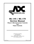
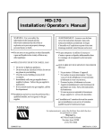
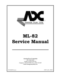
1
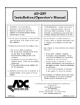
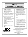
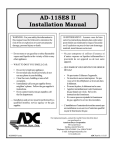
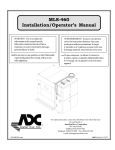
ADH-120/ADH-170
Installation/Operator’s Addendum
WARNING: For your safety the
information in this manual must be
followed to minimize the risk of fire or
explosion or to prevent property damage,
personal injury or death.
AVERTISSEMENT: Assurez-vous de bien
suivre les instructions données dans cette
notice pour réduire au minimum le risque
d’incendie ou d’explosion ou pour éviter tout
dommage matériel, toute blessure ou la mort.
Do not store or use gasoline or other flammable
vapor and liquids in the vicinity of this or any
other appliance.
Ne pas entreposer ni utiliser d’essence ni
d’autres vapeurs ou liquides inflammables dans
le voisinage de cet appareil ou de tout autre
appareil.
ADH-120 DRYER
ADH-170 DRYER
For replacement parts, contact the distributor from which the dryer
was purchased or
American Dryer Corporation
88 Currant Road
Fall River MA 02720-4781
Telephone: (508) 678-9000 / Fax: (508) 678-9447
E-mail: [email protected]
121099DX/tcosta
ADC Part No. 113117
Retain This Manual In A Safe Place For Future Reference
American Dryer Corporation products embody advanced concepts in engineering, design, and safety. If this product is
properly maintained, it will provide many years of safe, efficient, and trouble-free operation.
ONLY qualified technicians should service this equipment.
OBSERVE ALL SAFETY PRECAUTIONS displayed on the equipment or specified in the installation/operator's manual
included with the dryer.
The following “FOR YOUR SAFETY” caution must be posted near the dryer in a prominent location.
FOR YOUR SAFETY
POUR VOTRE SÉCURITÉ
Do not store or use gasoline or
other flammable vapors or liquids
in the vicinity of this or any other
appliance.
Ne pas entreposer ni utiliser d’essence
ni d’autres vapeurs ou liquides
inflammables dans le voisinage de cet
appareil ou de yout autre appareil.
We have tried to make this manual as complete as possible and hope you will find it useful. ADC reserves the right to make
changes from time to time, without notice or obligation, in prices, specifications, colors, and material, and to change or
discontinue models.
Important
For your convenience, log the following information:
DATE OF PURCHASE
MODEL NO.
DISTRIBUTORS NAME
Serial Number(s)
Replacement parts can be obtained from your distributor or the ADC factory. When ordering replacement parts from the
factory, you can FAX your order to ADC at (508) 678-9447 or telephone your orders directly to the ADC Parts Department at
(508) 678-9000. Please specify the dryer model number and serial number in addition to the description and part number, so
that your order is processed accurately and promptly.
IMPORTANT
YOU MUST DISCONNECT and LOCKOUT THE ELECTRIC SUPPLY and THE STEAM
SUPPLY BEFORE ANY COVERS or GUARDS ARE REMOVED FROM THE MACHINE
TO ALLOW ACCESS FOR CLEANING, ADJUSTING, INSTALLATION, or TESTING
OF ANY EQUIPMENT per OSHA (Occupational Safety and Health Administration)
STANDARDS.
“Caution: Label all wires prior to
disconnection when servicing controls. Wiring
errors can cause improper operation.”
«Attention: Lor des opérations d’entretien
des commandes étiqueter tous fils avant
de les déconnecter. Toute erreur de
câblage peut étre une source de danger et
de panne.»
CAUTION
DRYERS SHOULD NEVER BE LEFT UNATTENDED WHILE IN OPERATION.
WARNING
CHILDREN SHOULD NOT BE ALLOWED TO PLAY ON OR NEAR THE DRYER(S).
CHILDREN SHOULD BE SUPERVISED IF NEAR DRYERS IN OPERATION.
FOR YOUR SAFETY
DO NOT DRY MOP HEADS IN THE DRYER.
DO NOT USE DRYER IN THE PRESENCE OF DRY CLEANING FUMES.
WARNING
UNDER NO CIRCUMSTANCES should the door switch or the heat circuit devices
ever be disabled.
WARNING
The dryer must never be operated with any of the back guards, outer tops, or service
panels removed. PERSONAL INJURY or FIRE COULD RESULT.
WARNING
DRYER MUST NEVER BE OPERATED WITHOUT THE LINT FILTER/SCREEN IN
PLACE, EVEN IF AN EXTERNAL LINT COLLECTION SYSTEM IS USED.
IMPORTANT
PLEASE OBSERVE ALL SAFETY PRECAUTIONS displayed on the equipment and/or
specified in the installation and operator's manual included with the dryer.
Dryers must not be installed or stored in an area where it will be exposed to water or weather.
The wiring diagram for the dryer is located in the front electrical control box area.
Table of Contents
SECTION I
IMPORTANT INFORMATION ................................................................................................................. 2
A. RECEIVING and HANDLING ........................................................................................................ 2
B. SAFETY PRECAUTIONS .............................................................................................................. 3
SECTION II
SPECIFICATIONS/COMPONENT IDENTIFICATION .............................................................................. 5
A. SPECIFICATIONS (Electric and Steam ONLY) ................................................................................ 5
B. SPECIFICATIONS (Steam ONLY) .................................................................................................. 6
C. COMPONENT IDENTIFICATION ................................................................................................. 8
SECTION III
INSTALLATION PROCEDURES ............................................................................................................ 12
A. LOCATION REQUIREMENTS ..................................................................................................... 12
B. UNPACKING/SETTING UP ......................................................................................................... 13
C. DRYER ENCLOSURE REQUIREMENTS ...................................................................................... 15
D. FRESH AIR SUPPLY ................................................................................................................... 15
E. EXHAUST REQUIREMENTS ...................................................................................................... 15
F. ELECTRICAL INFORMATION .................................................................................................... 15
G. STEAM INFORMATION ............................................................................................................. 16
H. FILTER INFORMATION ............................................................................................................. 21
I. PREPARATION FOR OPERATION ............................................................................................... 23
J. PREOPERATIONAL TESTS ........................................................................................................ 23
K. OPERATING INSTRUCTIONS .................................................................................................... 25
L. SHUT DOWN INSTRUCTIONS .................................................................................................. 26
SECTION IV
SERVICE/PARTS INFORMATION......................................................................................................... 27
A. SERVICE ................................................................................................................................... 27
B. PARTS ....................................................................................................................................... 27
SECTION V
WARRANTY INFORMATION ................................................................................................................ 28
A. RETURNING WARRANTY CARD(S) ........................................................................................... 28
B. WARRANTY .............................................................................................................................. 28
C. RETURNING WARRANTY PART(S) ............................................................................................ 28
SECTION VI
ROUTINE MAINTENANCE .................................................................................................................... 30
A. CLEANING ................................................................................................................................ 30
B. ADJUSTMENTS ......................................................................................................................... 32
C. LUBRICATION ........................................................................................................................... 32
SECTION VII
TROUBLESHOOTING ........................................................................................................................... 33
SECTION VIII
REVERSING TIMER SPIN/DWELL ADJUSTMENTS ............................................................................... 43
SECTION X
PROCEDURE FOR FUNCTIONAL CHECK OF REPLACEMENT COMPONENTS .................................... 44
SECTION I
IMPORTANT INFORMATION
A. RECEIVING and HANDLING
The dryer is shipped in a protective stretch wrap cover with protective cardboard corners and top cover (or
optional box) as a means of preventing damage in transit. Upon delivery, the dryer and/or packaging, and wooden
skid should be visually inspected for shipping damage. If any damage whatsoever is noticed, inspect further
before delivering carrier leaves.
Dryers damaged in shipment:
1. ALL dryers should be inspected upon receipt and before they are signed for.
2. If there is suspected damage or actual damage, the trucker’s receipt should be so noted.
3. If the dryer is damaged beyond repair, it should be refused. Those dryers which were not damaged in a
damaged shipment should be accepted, but the number received and the number refused must be noted
on the receipt.
4. If you determine that the dryer was damaged after the trucker has left your location, you should call the
delivering carrier’s freight terminal immediately and file a claim. The freight company considers this concealed
damage. This type of freight claim is very difficult to get paid and becomes extremely difficult when more
than a day or two passes after the freight was delivered. It is your responsibility to file freight claims.
Dryer/parts damaged in transit cannot be claimed under warranty.
5. Freight claims are the responsibility of the consignee, and ALL claims must be filed at the receiving end.
ADC assumes no responsibility for freight claims or damages.
6. If you need assistance in handling the situation, please contact the ADC Traffic Manager at (508) 678-9000.
IMPORTANT: The dryer must be transported and handled in an upright position at ALL times.
2
B. SAFETY PRECAUTIONS
WARNING: For your safety, the information in this manual must be followed to minimize the risk of
fire or explosion or to prevent property damage, personal injury, or loss of life.
WARNING: The dryer must never be operated with any of the back guards, outer tops, or
service panels removed. PERSONAL INJURY or FIRE COULD RESULT.
1. DO NOT store or use gasoline or other flammable vapors and liquids in the vicinity of this or any other
appliance.
2. Installation and service must be performed by a qualified installer or service agency.
3. Dryer(s) must be exhausted to the outdoors.
4. Although ADC produces a very versatile machine, there are some articles that, due to fabric composition or
cleaning method, should not be dried in it.
WARNING: Dry only water-washed fabrics. DO NOT dry articles spotted or washed in dry cleaning
solvents, a combustible detergent, or “all purpose” cleaner.
EXPLOSION COULD RESULT.
WARNING: DO NOT dry rags or articles coated or contaminated with gasoline, kerosene, oil, paint,
wax.
EXPLOSION COULD RESULT.
WARNING: DO NOT dry mop heads. Contamination by wax or flammable solvents will create a fire
hazard.
WARNING: DO NOT use heat for drying articles that contain plastic, foam, sponge rubber, or
similarly textured rubber materials. Drying in a heated tumbler (basket) may damage
plastics or rubber and also may be a fire hazard.
5. A program should be established for the inspection and cleaning of lint in the heating unit area, exhaust duct
work, and inside the dryer. The frequency of inspection and cleaning can best be determined from experience
at each location.
WARNING: The collection of lint in the burner area and exhaust duct work can create a potential fire
hazard.
6. For personal safety, the dryer must be electrically grounded in accordance with local codes and/or the
National Electrical Code ANSI/NFPA NO. 70-LATEST EDITION, or in CANADA, the Canadian Electrical
Codes Parts 1 & 2 CSA C22.1-1990 or LATEST EDITION.
NOTE: Failure to do so will VOID THE WARRANTY.
3
7. UNDER NO CIRCUMSTANCES should the dryer door switches, lint door switch, heat safety circuit
ever be disabled.
WARNING: PERSONAL INJURY or FIRE COULD RESULT.
8. This dryer is not to be used in the presence of dry cleaning solvents or fumes.
9. Remove articles from the dryer as soon as the drying cycle has been completed.
WARNING: Articles left in the dryer after the drying and cooling cycles have been completed can
create a fire hazard.
10. DO NOT operate steam dryers with more than 125 PSI (8.61 bar) steam pressure. Excessive steam
pressure can damage steam coil and/or harm personnel.
11. Replace leaking flexible hoses or other steam fixtures immediately. DO NOT operate the dryer with
leaking flexible hoses. PERSONAL INJURY MAY RESULT.
12. READ and FOLLOW ALL CAUTION and DIRECTION LABELS ATTACHED TO THE DRYER.
WARNING: YOU MUST DISCONNECT and LOCKOUT THE ELECTRIC SUPPLY and
THE STEAM SUPPLY BEFORE ANY COVERS or GUARDS ARE
REMOVED FROM THE MACHINE TO ALLOW ACCESS FOR CLEANING,
ADJUSTING, INSTALLATION, or TESTING OF ANY EQUIPMENT per
OSHA (Occupational Safety and Health Administration) STANDARDS.
4
SECTION II
SPECIFICATIONS/COMPONENT IDENTIFICATION
A. SPECIFICATIONS (Electric and Steam ONLY)
1. ADH-120
MAXIMUM CAPACITY (Dry Weight)
120 lbs.
54.4 kg
TUMBLER (Basket) DIAMETER
44-1/2"
113 cm
TUMBLER (Basket) DEPTH
42-1/2"
107.9 cm
TUMBLER (Basket) MOTOR
3/4 HP
.560 kw
3 HP
2.238 kw
31-3/8"
79.7 cm
38.2 cu. ft.
1.08 cu. m.
BLOWER MOTOR
DOOR OPENING (Diameter)
TUMBLER (Basket) VOLUME
Steam
Electric
Dryers Per 20'/40' Container
Dryers Per 45'/48' Truck
VOLTAGE AVAILABLE
3/7
9/9
208-600v 3Ø 3, 4w 50/60 Hz
OVEN SIZE
kw
btu/hr
kcal/hr
Airflow
72
246,150
61,982
2,150 cfm
60.1 cmm
80
273,500
68,869
2,500 cmm
70.1 cmm
VOLTAGE AVAILABLE
APPROX. WEIGHT (Uncrated)
208-460v 3Ø 3, 4w 50/60 Hz
1,650 lbs.
748.4 kg
APPROX. WEIGHT (Crated)
HEAT INPUT
1,875 lbs.
STEAM CONSUMPTION
450 lbs./hr
202.2 kg/hr
AIRFLOW
2,750 cfm
77.9 cmm
INLET SIZE
(2) 1-1/4"
---
RETURN SIZE
(2) 1-1/4"
---
COMPRESSED AIR CONNECTION
1/8" N.P.T.
---
COMPRESSED AIR REQUIREMENT
6 cfh @ 80 PSI
.017 cm m @ 5.512 bar
850.5 kg
13 Bhp
Shaded areas are stated in metric equivalents
IMPORTANT: Dryers must be provided with a clean, dry, regulated 80 PSI +/-10 PSI (5.512 bar
+/- 0.689 bar) air supply.
NOTE: ADC RESERVES THE RIGHT TO MAKE CHANGES IN SPECIFICATIONS AT ANY
TIME, WITHOUT NOTICE or OBLIGATION.
5
B. SPECIFICATIONS (Steam ONLY)
1. ADH-170
MAXIMUM CAPACITY (Dry Weight)
170 lbs.
77.1 kg
TUMBLER (Basket) DIAMETER
51-1/2"
130.8 cm
TUMBLER (Basket) DEPTH
42-1/2"
107.9 cm
TUMBLER (Basket) MOTOR
1 HP
.746 kw
7-1/2 HP
5.6 kw
31-3/8"
79.7 cm
51.2 cu. ft.
1.45 cu. m.
BLOWER MOTOR
DOOR OPENING (Diameter)
TUMBLER (Basket) VOLUME
Dryers Per 20'/40' Container
Dryers Per 45'/48' Truck
3/7
8/8
VOLTAGE AVAILABLE
208-600v 3Ø 3, 4w 50/60 Hz
APPROX. WEIGHT (Uncrated)
2,050 lbs.
929.3 kg
APPROX. WEIGHT (Crated)
2,220 lbs.
1,006.3 kg
Steam
HEAT INPUT
19 Bhp
STEAM CONSUMPTION
725 lbs./hr
329.1 kg/hr
AIRFLOW
4,400 cfm
124.56 cmm
INLET SIZE
1-1/2"
---
RETURN SIZE
1-1/2"
---
1/8" F.P.T.
---
6 cfh @ 80 PSI
.017 cm m @ 5.512 bar
COMPRESSED AIR CONNECTION
COMPRESSED AIR REQUIREMENT
Shaded areas are stated in metric equivalents
IMPORTANT: Dryers must be provided with a clean, dry, regulated 80 PSI +/-10 PSI (5.512 bar
+/- 0.689 bar) air supply.
NOTE: ADC RESERVES THE RIGHT TO MAKE CHANGES IN SPECIFICATIONS AT ANY
TIME, WITHOUT NOTICE or OBLIGATION.
6
Specifications
ADH-120
ADH-170
NOTE: ADC RESERVES THE RIGHT TO MAKE CHANGES IN SPECIFICATIONS AT ANY
TIME, WITHOUT NOTICE or OBLIGATION.
7
C. COMPONENT IDENTIFICATION
1. ADH-120 FRONT VIEW
Illus. No.
1
2
3
4
5
6
7
8
9
10
11
Description
Microprocessor Control/Keyboard (Touchpad) Panel Assembly (Controls)
Control (Top Access) Door Assembly
Main Door Assembly
Lint Chamber Access Panel
Lint Screen
Wire Diagram (Located Behind Control Door)
Filter Housing Assembly
Steam Damper Assembly
Lint Door
Differential Pressure Gauge and High Temp Alarm Panel
Door Interlock
8
2. ADH-120 REAR VIEW
Illus. No.
1
2
3
4
5
6*
7
8
9
*
Description
Basket (Drive) Motor Assembly
Blower Motor Mount Assembly
Impellor (Fan/Blower) Assembly
Idler Bearing Mount Assembly
Tumbler Bearing Mount Assembly
Electric Service Relay Box
Filter Housing
Steam Coil
Filter Access Panel
Electric service connections are made in this box for steam only.
9
3. ADH-170 FRONT VIEW
Illus. No.
1
2
3
4
5
6
7
8
9
10
11
12
13
Description
Microprocessor Control/Keyboard (Touchpad) Panel Assembly (Controls)
Control (Top Access) Door Assembly
Main Door Assembly
Lint Door Assembly
Lint Chamber Access Panel
Wire Diagram
Top Console (Module) Assembly
Data Label and Installation Label
Door Interlock
Lint Screen
Differential Pressure /High Temp Alarm Panel
Filter Housing
Steam Damper Assembly
10
4. ADH-170 REAR VIEW
Illus. No.
1
2
3
4
5*
6
7
8
9
10
11
*
Description
Basket (Drive) Motor Assembly
Blower Motor Mount Assembly
Idler Bearing Mount Assembly
Tumbler Bearing Mount Assembly
Electric Service Relay Box
Steam Damper
Filter Access Panel
1/8” Compressed Air Supply Inlet (Behind Gusset)
Side Access Opening
Front Access Opening
Impellor (Fan) Assembly
Electric service connections are made in this box for steam only.
11
SECTION III
INSTALLATION PROCEDURES
Installation should be performed by competent technicians in accordance with local and state codes. In the
absence of these codes, the installation must conform to applicable AMERICAN NATIONAL STANDARDS:
ANSI.Z223.1-LATEST EDITION (National Fuel Gas Code)
and/or
ANSI/NFPA NO. 70-LATEST EDITION (National Electrical Code)
or in CANADA, the installation must conform to applicable CANADIAN STANDARDS:
CAN/CGA-B149.1-M91 (Natural Gas) or CAN/CGA-B149.2-M91 (L.P. Gas) or LATEST EDITION
(for GENERAL INSTALLATION and GAS PLUMBING)
and/or
CANADIAN ELECTRICAL CODES PARTS 1 & 2 CSA C22.1-1990 or LATEST EDITION
(for ELECTRICAL CONNECTIONS).
A. LOCATION REQUIREMENTS
Before installing the dryer, be sure the location conforms to local codes and ordinances. In the absence of such
codes or ordinances the location must conform with the National Fuel Gas Code ANSI.Z223.1-LATEST
EDITION, or in CANADA, the Canadian Installation Codes CAN/CGA-B149.1-M91 (Natural Gas) or CAN/
CGA-B149.2-M91 (L.P. Gas) or LATEST EDITION.
1. The dryer must be installed on a sound level floor capable of supporting its weight. It is recommended that
carpeting be removed from the floor area that the dryer is to rest on.
2. The dryer must not be installed or stored in an area where it will be exposed to water and/or weather.
3. Provisions for adequate air supply must be provided as noted in this manual (refer to Fresh Air Supply in
Section D).
4. Clearance provisions must be made from combustible construction as noted in this manual (refer to Dryer
Enclosure Requirements in Section C).
5. Provisions must be made for adequate clearances for servicing and for operation as noted in this manual
(refer to Dryer Enclosure Requirements in Section C).
6. Dryer must be exhausted to the outdoors (refer to Exhaust Requirements in Section E).
7. Dryer must be located in an area where correct exhaust venting can be achieved as noted in the manual
(refer to Exhaust Requirements in Section E).
8. Dryer must be located in an area where correct exhaust venting can be achieved as noted in this manual
(refer to Exhaust Requirements in Section E).
IMPORTANT: Dryer should be located where a minimum amount of exhaust duct will be necessary.
12
B. UNPACKING/SETTING UP
Remove protective shipping material (i.e., plastic wrap and/or optional shipping box) from dryer.
IMPORTANT: Dryer must be transported and handled in an upright position at ALL times.
The dryer can be moved to its final location while still attached to the skid or with the skid removed. To un-skid
the dryer, locate, and remove the four (4) lag bolts securing the base of the dryer to the wooden skid. Two (2) are
located at the rear base (remove the back panel for access), and two (2) are located in the bottom of the lint
chamber. To remove the two (2) lag bolts located in the lint chamber area, remove the lint drawer and the three
(3) Phillips head screws securing lint door in place.
13
1. LEVELING DRYER
a. To level dryer, place 4-inch (10.16 cm) square metal shims (refer to illustration on previous page [page
13]) or other suitable material under the base pads. It is suggested that the dryer be tilted slightly to the
rear.
2. If more headroom is needed when moving dryer into position, the top console (module) may be removed.
a. To remove top console (module)
1) Disconnect the ground wire (A) at the Rear Upper Left Hand Corner of Dryer.
2) Remove the six (6) set of nuts and washers (B) holding the console (module) to base.
3) Open the control door/control panel and disconnect the white 15-pin plug connector (C in the illustration
below) located in the base of the control box.
4) Disconnect white plug connector located outside backside of the control box (provides power to heat
circuit).
5) Lift the console (module) off of the dryer base.
IMPORTANT: The dryer must be transported and handled in an upright position at ALL times.
14
C. DRYER ENCLOSURE REQUIREMENTS
Even though a 12-inch (30.48 cm) clearance is acceptable, it is recommended that the rear of the dryer be
positioned approximately 2 feet (0.609 meter) from the nearest obstruction (i.e., wall) for ease of installation,
maintenance, and service. Bulkheads and partitions should be made from noncombustible materials. The
clearance between the bulkhead header and the dryer must be a minimum of 4-inches (10.16 cm) and must not
extend more than 4-inches (10.16 cm) to the rear of the dryer front. The bulkhead facing must be made of a
noncombustible material in ALL the way to the top of the dryer.
NOTE: Bulkhead facing should not be installed until after dryer is in place. Ceiling area must be
located a minimum of 12-inches (30.48 cm) above the top of the dryer.
IMPORTANT: Even though a minimum of only 12-inches (30.48 cm) is required, 18-inches (45.72
cm) or more is suggested, for steam dryers and especially in cases where sprinkler
heads are over the dryers.
NOTE: When fire sprinkler systems are located above the dryers, a minimum of 18-inches (45.72 cm)
above the dryer console (module) is suggested. Dryers may not be positioned side wall to side
wall due to side lint clean-out door.
D. FRESH AIR SUPPLY (Refer to Appropriate ADH-120/170 Installation/Operator’s Manual)
E. EXHAUST REQUIREMENTS (Refer to Appropriate ADH-120/170 Installation/Operator’s Manual)
F. ELECTRICAL INFORMATION (Refer to Appropriate ADH-120/170 Installation/Operator’s Manual)
15
G. STEAM INFORMATION
It is your responsibility to have ALL steam plumbing connections made by a qualified professional to assure that
the installation is adequate and conforms with local and state regulations or codes.
IMPORTANT: Failure to comply with the requirements stipulated in this manual can result in
component failurewhichwill VOID THE WARRANTY.
NOTE: The ADH-120 and ADH-170 are manufactured with a pneumatic (piston) damper system
which requires an external supply of clean, dry, regulated air at 80 psi +/- 10 psi (5.512 bar +/.689 bar). Refer to Steam Damper Air System Connections , Section G, item 3.
1. STEAM COIL PH LEVEL
The normal PH level for copper type steam coils must be maintained between a value of 8.5 to 9.5. For
steel type steam coils the PH level must be maintained between a value of 9.5 to 10.5. These limits are set
to limit the acid attack of the steam coils.
IMPORTANT: Coil failure due to improper PH level will VOID THE WARRANTY.
2. STEAM REQUIREMENTS, HIGH PRESSURE
a. Inlet------ADH-120 1-1/4-inch supply line connection --- qty. one (1) at top manifold for each of the two
(2) steam coils.
ADH-170 1-1/2-inch supply line connection --- qty. one (1) at top manifold.
b. Return--- ADH-120 1-1/4-inch return line connection --- qty. one (1) at bottom manifold for each of the
two (2) steam coils.
ADH-170 1-1/2-inch return line connection --- qty. one (1) at bottom manifold.
Operating Steam Pressure
ADH-120
ADH-170
Maximum
125 psig
862 kPa
125 psig
862 kPa
Minimum
100 psig*
689 kPa
100 psig*
689 kPa
Heat Input (Normal Load)
Consumption (Approximate)
13 Bhp
450 lbs/hr
204 kg/hr
19 Bhp
725 lbs/hr
329 kg/hr
Shaded areas are stated in metric equivalents
* Minimum operating pressure for optimium results.
3. INSTALLATION INSTRUCTIONS
To insure that an adequate supply of steam is provided, be sure that the steam supply and steam return lines
are sized and laid out as stipulated in this manual. Inadequate steam supply and steam return lines are sized
and laid out as stipulated in this manual. Inadequate steam supply and steam return lines or improper steam
plumbing will result in poor performance and can cause component failure. Clean, dry, regulated steam
must be provided to the dryer.
16
IMPORTANT: Steam coil failure due to water hammer by wet steam will VOID THE WARRANTY.
a. The pressure of the condensate in the steam supply will cause water hammer and subsequent heat
exchanger (steam coil) failure. The steam supply connection into the main supply line must be made.
b. The steam supply piping to the dryer must include a 12-inch (30.48 cm) rise along with a drip trap and
check valve. This will prevent any condensate from entering the steam coil.
c. Flexible hoses or couplings must be used. The dryer vibrates slightly when it runs and this will cause the
steam coil connections to crack if they are hard piped to the supply and return mains.
d. Shut-off valves for each dryer should be installed in the supply, return, and drip trap return lines. This
will allow the dryer to be isolated from the supply and return mains if the dryer needs maintenance work.
e. Install an inverted bucket steam trap and check valve for each unit at least 12-inches (30.48 cm) below
steam coil as close to the coil as possible.
1) A trap with a capacity of 1,200 pounds (544 kg) of condensate per hour at 125 psi (8.6125 bar) is
needed for each ADH-120.
2) A trap with a capacity of 1,400 pounds (635.03 kg) of condensate per hour at 125 psi (8.6125 bar) is
needed for each ADH-170.
f. A 3/4” vacuum breaker should be installed for each unit in the piping. This will prevent the condensing
steam from causing a vacuum inside the coil and possibly damaging the coil.
g. The supply and return lines should be insulated. This will save energy and provide for safety of the
operator and maintenance personnel.
h. Water pockets in the supply line, caused by low points, will provide wet steam to the coil possibly causing
coil damage. ALL horizontal runs of steam supply piping should be pitched 1/4-inch (0.64 cm) for every
one (1) foot (30.4 cm) back towards the steam supply header causing any condensate in the line to drain
to the header. Install a bypass trap in any low point to eliminate wet steam.
17
3. STEAM DAMPER AIR SYSTEM CONNECTIONS
The ADH-120 and ADH-170 is manufactured with a pneumatic (piston) damper system or door interlock
which requires an external supply of clean compressed air. The air connection is made to the steam damper
solenoid valve which is located at the rear inner top area of the dryer just above the electric service relay
box (refer to the bottom illustration on page 19).
a. Air Requirements
Compressed Air Supply
Air Pressure
Normal
80 psi
5.51 bar
Minimum Supply
70 psi
4.82 bar
Maximum Supply
90 psi
6.201 bar
Shaded areas are stated in metric equivalents
b. Air Connection
Air connection to system --- 1/8-inch N.P.T.
c. No air regulation or filtration is provided with the dryer. External regulation/filtration of 80 psi (5.51 bar)
must be provided. It is suggested that a regulator/filter gauge arrangement be added to the compressed
air line just before the dryer connection. This is necessary to insure that correct and clean air pressure
is achieved.
4. ADS-120 STEAM DAMPER AIR PISTON OPERATION ADJUSTMENT
When installing or adjusting the ADH-120 steam damper the following steps must be taken for proper
operation of the system.
a. The linkage support assembly is placed on the center bar inside the plenum between the coils. The assembly
must be positioned such that the locking collar is facing the rear of the dryer. When installing, examine the
linkage assembly to be certain that collar has been welded on the proper side of the assembly. Refer to
figure 1. The collar should not be locked into place on the center bar yet.
b. Facing the front of the coil assembly, the small linkage arm will be fastened to the left side of the linkage
assembly and the large linkage arm will be positioned to the right. Each linkage is fastened with a clevis pin,
a cotter pin, and a sufficient number of washers to allow the linkage to swivel without sloppiness.
c. The opposite side of each linkage will then be fastened to the appropriate damper assembly. There are five
(5) holes on each damper flange. The best adjustment is usually found in the center hole. However, this
may not hold true on every damper assembly due to manufacturing tolerances. The linkage is then fastened
to the damper flange in the same manner as step two (2). Refer to figure 1. The linkage support assembly
should be turned counterclockwise (CCW) until the damper assemblies seat securely against the steam
coils and the set screw is to be tightened securely.
d. The lever arm assembly should then be positioned on the center bar on the front of the steam damper
assembly. With the damper assemblies seating securely against the steam coils, the lever arm should be
positioned between 8:00 and 9:00. These connections are all shown in figure 2.
18
e. Once the connections are ALL made, turn the activating bracket assembly clockwise (CW). The entire
assembly should turn freely without binding or excessive force. The bottom of the damper assemblies
should both meet approximately in the center of the plenum. The damper assemblies should meet almost
flush. Refer to figure 3. If the dampers resist closing or if they DO NOT meet almost flush, it may be
necessary to move either one or both of the linkages up or down on the damper flange depending on the
adjustment required.
f.
Once proper adjustment has been accomplished, power up the machine and activate a cycle. Observe the
closing of the damper assembly. Again the dampers must meet. If they DO NOT it may be necessary to
readjust again. The misalignment may also be due to loose set screws. If proper adjustment cannot be
obtained, contact the technical support department at ADC for assistance.
19
5. ADH-120 STEAM DAMPER SYSTEM OPERATION
The ADH-120 steam damper, as shown below, allows the coil to stay constantly charged eliminating repeated
expansion and contraction. When the damper is opened, the air immediately passes through the already hot
coil, providing instant heat to start the drying process. When the damper is closed, ambient air is drawn
directly into the tumbler (basket), allowing a rapid cool down.
Diagram 1 -- shows the damper in the heating (open) mode, allowing heat into the tumbler (basket).
Diagram 2 -- shows the damper in the cool down (closed) mode, pulling ambient air directly into the tumbler
(basket) without passing through the coils.
NOTE: With the dryer off or with no air supply, the damper is in the cool down mode as shown in
Diagram 2.
6. ADH-170 STEAM DAMPER AIR PISTON (FLOW CONTROL) OPERATION ADJUSTMENT
Although the damper operation was tested and adjusted prior to shipping at 80 psi (5.51 bar), steam damper
operation must be checked before the dryer is put into operation. Refer to page 24, section 5b for
instructions to check system damper operation. If damper air adjustment is necessary, locate flow control
valve and make necessary adjustments as noted on page 21.
20
H. FILTER INFORMATION
The filter housing is where the pre-filters and HEPA filters
are contained. On the upper most rails is where the pre-filters
are installed and on the rails below that, the HEPA filters are
installed. The ADH-120 requires two (2) of each pre-filters
and HEPA filters, where the ADH-170 requires four (4) of
each pre-filters and HEPA filters.
1. FILTER REQUIREMENT:
Filter Description
Pre-filter
HEPA/ULPA
H
24"
60.96 cm
24"
60.96 cm
OPERATING
Quantity
ADH-120 ADH-170
TEMP
24"
2"
1100
250º F
2
4
60.96 cm 5.08 cm 31.15 cmm 121º C
24"
11-1/2"*
1100
250º F
2
4
60.96 cm 29.21 cm 31.15 cmm 121º C
W
D
Shaded areas are stated in metric equivalents
*Does not include 1/4" thick gasket
21
CFM
2. FILTER REPLACEMENT
The frequency at which filters have to be replaced is best determined by each location.
NOTE: On electric dryers, if the static pressure across the filters exceeds 1-inch water column
(2.488 mbar), the heat circuit will shut down.
a. Verify main door is closed (this is to eliminate contamination of clean room).
b. Discontinue electrical power to the dryer.
c. Remove filter access cover plate.
d. Remove pre-filters.
e. Remove HEPA filters.
f. Replace both HEPA and pre-filters.
g. Reinstall filter cover plate.
h. Perform any necessary scrubbing of the dryer.
i. Reestablish electrical power to the dryer.
22
I. PREPARATION FOR OPERATION
The following items should be checked before attempting to operate the dryer:
1. Read ALL “CAUTION,” “WARNING,” and “DIRECTION” labels attached to the dryer.
2. Check incoming supply voltage to be sure that it is the same as indicated on the dryer data label located in
the front top console area as shown on page 8 for the ADH-120 and page 10 for the ADH-170. In case
of 208 VAC or 230/240 VAC, the supply voltage must match the electric service exactly.
3. Be sure ALL back panels (guards) and electric box covers have been replaced.
4. Check ALL service doors to assure that they are closed and secured in place.
5. Be sure lint drawer is securely in place.
6. Verify pre and HEPA filters have been installed.
NOTE: LINT DRAWER MUST BE ALL THE WAY IN PLACE TO ACTIVATE SAFETY
SWITCH, OTHERWISE THE DRYER WILL NOT START.
7. Rotate the tumbler (basket) by hand to be sure it moves freely.
8. Check bolts, nuts, screws, terminals, and fittings for security.
9. Check to insure air supply (80 psi [5.51 bar]) is on to the dryer.
10. STEAM MODELS - check to insure ALL steam shut-off valves are open.
11. STEAM MODELS - check steam damper operation.
12. Check tumbler bearing set screws to insure they are ALL tight.
J. PREOPERATIONAL TESTS
ALL dryers are thoroughly tested and inspected before leaving the factory. However, a preoperational test
should be performed before the dryer is publicly used. It is possible that adjustments have changed in transit or
due to marginal location (installation) conditions.
1. Turn on electric power to the dryer.
2. Make sure the main door is closed and the lint drawer is securely in place.
3. Refer to the Operating Instructions for starting your particular dryer.
4. Check to insure that the tumbler (basket) starts in the clockwise (CW) direction. Additionally, check the
direction of the blower motor impellor (fan) to insure that impellor (fan/blower) rotates in the clockwise
(CW) direction as viewed from the front. If it is, the phasing is correct. If the phasing is incorrect, reverse
two (2) of the leads at L1 and L3 of the power supply connections made to the dryer.
23
IMPORTANT: Dryer blower motor impellor/fan as viewed from the front must turn in the clockwise
(CW) direction, otherwise dryer efficiency will drastically be reduced and premature
component failure can result.
5. HEAT CIRCUIT OPERATIONAL TEST
a Electric Models
1) Check the oven contactor(s) to insure that the electric oven is cycling properly.
b. Steam Models
1) Check to insure that steam damper is functioning properly.
a) The steam damper should not “slam” (open or closed) when it reaches the end of (piston)
travel. Additionally, the steam damper should not bind and/or stop during travel. If either of
these conditions occur, the flow control must be adjusted. Refer to the top illustration on page
21 for air adjustment instructions.
6. Make a complete operational check of ALL safety-related circuits (i.e., lint drawer switch and sail switch).
NOTE: To check for proper sail switch operation, open the main door and while holding main door
switch plunger in, start dryer. Dryer should start but heat circuit should not be activated (on).
If heat (burner) does activate, shut dryer off and make necessary adjustments.
7. A reversing tumbler (basket) dryer should never be operated with less than a 60 lb. (27.21 kg) load (dry
weight). The size of the load will affect the coast-down and dwell (stop) times. The tumbler (basket) must
come to a complete stop before starting in opposite direction.
a. Microprocessor (computer) Dryer Models
1) Spin and stop times are not adjustable in the Automatic Mode and have been preprogrammed into
the microprocessor controller (computer) for 120-seconds spin time and a 5-second dwell (stop)
time.
2) Spin and stop times are adjustable in the Manual (timed) Mode.
b. Dual Timer Dryer Models
1) Spin and stop times are adjustable at the reversing timer (refer to page 43).
IMPORTANT: The dryer tumbler (basket) is treated with a protective coating ADC suggests tumbling
old clothes or material in the tumbler (basket), using a mild detergent to remove the
protective coating.
8. Each dryer should be operated through one complete cycle to assure that no further adjustments are
necessary and that ALL components are functioning properly.
24
9. Make a complete operational check of ALL operating controls.
a. Microprocessor controller (computer) programs/selections...
1) Each microprocessor controller (computer) has been preprogrammed by the factory with the most
commonly used parameter (program) selections. If computer program changes are required, refer
to the computer programming manual which was shipped with the dryer.
b. Dual timer dryers check...
1) Heating Timer
2) Cool Down Timer
3) Temperature Selection Switch
K. OPERATING INSTRUCTIONS
NOTE: Before attempting to start the dryer make sure that the main door is closed and the lint drawer
is securely in place.
1. To start the dryer.
a. Microprocessor (Computer) Dryers
1) Display will read “FILL” (meaning no cycle in progress).
2) Press the letter on the keyboard (touchpad) corresponding to the cycle desired (i.e., “E”)...
a) The dryer will then start (rotate).
3) L.E.D. (light emitting diode) display will now show the Cycle in progress and Cycle status (i.e.,
“dr30”) meaning that the dryer is in the drying cycle (dry mode for 30 minutes) and count down in
minutes.
NOTE: Pressing keyboard (touchpad) key “A,” “B,” “C,” “D,” and “F” will also start the dryer. The
six (6) preprogrammed drying cycles (“A” through “F”) have been stored in the microprocessor
(computer’s) memory. Refer to the Computer Programming Manual supplied with dryer for
more specific operating information.
NOTE: The dryer can be stopped at any time by pressing the “CLEAR/STOP” key. To restart the
dryer, press the “ENTER/START” key or preprogrammed cycle key (i.e., “E”).
NOTE: Selection (setting) changes can be made at any time during the drying cycle by pressing the
“CLEAR/STOP” key twice. The L.E.D. (light emitting diode) display will return to “FILL” at
which time a new cycle selection can be made.
25
b. Dual Timer Dryers
1) Select Drying Time and Cool Down Time desired...
a) Turn Heat Timer clockwise (CW) to desired time (i.e., 1 minute to 60 minutes).
b) Turn Cool Down Timer clockwise (CW) to desired time (i.e., 0 minutes to 30 minutes).
2) Select Drying Temperature (“HI TEMP,” “LO TEMP,” or “PERM PRESS”).
3) Push “Push to Start” switch...
a) Dryer will now start.
4) To stop dryer, turn dry and cool down timer to off.
L. SHUT DOWN INSTRUCTIONS
If the dryer is to be shut down (taken out of service) for a period of time, the following must be performed:
1. Discontinue power to the dryer either at the external disconnect switch or the circuit breaker.
2. STEAM MODELS ... discontinue the steam supply.
a. SHUT OFF steam valves in the supply lines and the return lines.
26
SECTION IV
SERVICE/PARTS INFORMATION
A. SERVICE
1. Service must be performed by a qualified trained technician, service agency, or gas supplier. If service is
required, contact the distributor from whom the ADC equipment was purchased. If the distributor cannot
be contacted or is unknown, contact the ADC Service Department for a distributor in your area.
NOTE: When contacting the ADC Service Department, be sure to give them the correct model
number and serial number so that your inquiry is handled in an expeditious manner.
B. PARTS
1. Replacement parts should be purchased from the distributor from whom the ADC equipment was
purchased. If the distributor cannot be contacted or is unknown, contact the ADC Parts Department for a
distributor in your area. Parts may also be purchased directly from the factory by calling the ADC Parts
Department at (508) 678-9000 or you may FAX in your order at (508) 678-9447.
NOTE: When ordering replacement parts from the ADC dealer or the ADC factory be sure to give
them the correct model number and serial number so that your parts order can be processed
in an expeditious manner.
27
SECTION V
WARRANTY INFORMATION
A. RETURNING WARRANTY CARD(S)
1. Before any dryer leaves the ADC factory test area, a warranty card is placed on the back side of the main
door glass. These warranty cards are intended to serve the customer, where we record the individual
installation date and warranty information to better serve you should you file a warranty claim.
a. If a warranty card did not come with your dryer, contact the ADC Warranty Department or ADC
Service Department at (508) 678-9000.
IMPORTANT: A separate warranty card must be completed and returned for each individual dryer.
NOTE: Be sure to include the installation date when returning the warranty card(s).
B. WARRANTY
For a copy of the ADC commercial warranty covering your particular dryer(s), contact the ADC distributor from
whom you purchased the equipment and request dryer warranty form. If the distributor cannot be contacted or
is unknown, warranty information can be obtained from the factory by contacting the ADC Warranty Department
at (508) 678-9000.
NOTE: Whenever contacting the ADC factory for warranty or warranty information, be sure to have
the dryer’s model number and serial number available so that your inquiry can be handled in
an expeditious manner.
C. RETURNING WARRANTY PART(S)
ALL dryer or parts warranty claims or inquiries should be addressed to the ADC Warranty Parts Department.
To expedite processing, the following procedures must be followed:
1. No parts are to be returned to ADC without prior written authorization (“Return Material Authorization”)
from the factory.
NOTE: An R.M.A. (“Return Material Authorization”) is valid for only sixty (60) days from date of issue.
a. The R.M.A. issued by the factory, as well as any other correspondence pertaining to the returned part(s),
must be included inside the package with the failed merchandise.
28
2. Each part must be tagged with the following information:
a. Model number and serial number of the dryer from which part was removed.
b. Nature of failure (be specific).
c. Date of dryer installation.
d. Date of part failure.
e. Specify whether the part(s) being returned is for a replacement, a credit, or a refund.
NOTE: If a part is marked for a credit or a refund, the invoice number covering the purchase of the
replacement part must be provided.
NOTE: Warranty tags (ADC Part No. 450064) are available at “no charge” from ADC upon request.
3. The company returning the part(s) must clearly note the complete company name and address on the
outside of the package.
4. ALL returns must be properly packaged to insure that they are not damaged in transit. Damage claims
are the responsibility of the shipper.
IMPORTANT: No replacements, credits or refunds will be issued for merchandise damaged in transit.
5. ALL returns should be shipped to the ADC factory in such a manner that they are insured and a proof of
delivery can be obtained by the sender.
6. Shipping charges are not the responsibility of ADC. ALL returns should be “prepaid” to the
factory. Any “C.O.D.” or “COLLECT” returns will not be accepted.
IMPORTANT: No replacements, credits, or refunds will be issued if the claim cannot be processed
due to insufficient information. The party filing the claim will be notified in writing,
either by “FAX” or “CERTIFIED MAIL - Return Receipt Requested,” as to the
information necessary to process claim. If a reply is not received by the ADC
Warranty Department within thirty (30) days from the FAX/letter date, then no
replacement, credit, or refund will be issued, and the merchandise will be discarded.
29
SECTION VI
ROUTINE MAINTENANCE
A. CLEANING
A program and/or schedule should be established for periodic inspection, cleaning, and removal of lint from
various areas of the dryer, as well as throughout the duct work system. The frequency of cleaning can best be
determined from experience at each location. Maximum operating efficiency is dependent upon proper air
circulation. The accumulation of lint can restrict this airflow. If the guidelines in this section are met, an ADC
dryer will provide many years of efficient, trouble-free, and - most importantly - safe operation.
WARNING: LINT FROM MOST FABRICS IS HIGHLY COMBUSTIBLE. THE
ACCUMULATION OF LINT CAN CREATE A POTENTIAL FIRE HAZARD.
WARNING: KEEP DRYER AREA CLEAR and FREE FROM COMBUSTIBLE
MATERIALS, GASOLINE, and OTHER FLAMMABLE VAPORS and
LIQUIDS.
NOTE: Suggested time intervals shown are for average usage which is considered six (6) to eight (8)
operational (running) hours per day.
Clean the lint screen every third or fourth load.
NOTE: Frequency can best be determined at each location.
SUGGESTED CLEANING SCHEDULE
DAILY (beginning of each work shift)
1. Clean lint from screen.
2. Inspect lint screen and replace if torn.
WEEKLY
Clean lint accumulation from lint chamber, thermostat, and microprocessor temperature sensor (sensor bracket)
area.
WARNING: TO AVOID THE HAZARD OF ELECTRICAL SHOCK, DISCONTINUE
ELECTRICAL SUPPLY TO THE DRYER.
30
STEAM DRYERS
Clean the steam coil fins. We suggest using compressed air and a vacuum cleaner with brush attachment.
WARNING: When cleaning steam coil fins, be careful not to bend the fins. If fins are bent, straighten
by using a fin comb which is available from local air conditioning supply houses.
90 DAYS
Remove lint from around tumbler (basket), drive motors, and surrounding areas. Remove lint from gas valve
burner area with a dusting brush or vacuum cleaner attachment.
NOTE: To prevent damage, avoid cleaning and/or touching ignitor/flame-probe assembly.
Remove lint accumulation from inside control box and at the rear area behind control box.
Impellor (fan/blower) shaft bearings should be lubricated. Use a #3 grease or equivalent.
6 MONTHS
Inspect and remove lint accumulation in customer furnished exhaust duct work system and from dryers internal
exhaust ducting.
Impellor (fan/blower) belts and drive belts should be examined. Cracked and/or seriously frayed belts should
be replaced. Tighten belts when necessary.
WARNING: THE ACCUMULATION OF LINT IN THE EXHAUST DUCT WORK CAN
CREATE A POTENTIAL FIRE HAZARD.
WARNING: DO NOT OBSTRUCT THE FLOW OF COMBUSTION and VENTILATION AIR.
CHECK CUSTOMER FURNISHED BACK DRAFTED DAMPERS IN EXHAUST
DUCT WORK. INSPECT and REMOVE ANY LINT ACCUMULATION WHICH
CAN CAUSE DAMPER TO BIND or STICK.
NOTE: A back draft damper that is sticking partially closed can result in slow drying and shutdown of
the heat circuit safety switches or thermostats.
NOTE: When cleaning dryer cabinet(s), avoid using harsh abrasives. A product intended for the
cleaning of appliances is recommended.
31
B. ADJUSTMENTS
7 DAYS AFTER INSTALLATION and EVERY 6 MONTHS THEREAFTER
Inspect bolts, nuts, screws, (bearing set screws), non-permanent gas connections (unions, shut-off valves, orifices,
and grounding connections). Motor and drive belts should be examined. Cracked or seriously frayed belts
should be replaced. Tighten loose V-belts when necessary. Complete operational check of controls and
valves. Complete operational check of ALL safety devices (door switches, lint drawer switch, sail switch,
burner, and hi-limit thermostats).
C. LUBRICATION
1. Impellor (fan/blower) shaft bearings should be lubricated every three (3) months. Use a #3 grease or
equivalent.
2. The motor bearings, idler bearings, and tumbler bearings are permanently lubricated. NO LUBRICATION
IS NECESSARY.
32
SECTION VII
TROUBLESHOOTING
IMPORTANT: YOU MUST DISCONNECT and LOCKOUT THE ELECTRIC SUPPLY and
THE STEAM SUPPLY BEFORE ANY COVERS or GUARDS ARE
REMOVED FROM THE MACHINE TO ALLOW ACCESS FOR
CLEANING, ADJUSTING, INSTALLATION, or TESTING OF ANY
EQUIPMENT per OSHA (Occupational Safety and Health Administration)
STANDARDS.
The information provided will help isolate the most probable component(s) associated with the difficulty
described. The experienced technician realizes, however, that a loose connection or broken/shorted wire may be
at fault where electrical components are concerned ... and not necessarily the suspected component itself.
Electrical parts should always be checked for failure before being returned to the factory.
The information provided should not be misconstrued as a handbook for use by an untrained person making
repairs.
IMPORTANT: When replacing blown fuses, the replacement must be of the exact rating as the fuse
being replaced.
WARNING: ALL SERVICE and TROUBLESHOOTING SHOULD BE PERFORMED BY A
QUALIFIED PROFESSIONAL or SERVICE AGENCY.
WARNING: WHILE MAKING REPAIRS, OBSERVE ALL SAFETY PRECAUTIONS
DISPLAYED ON THE DRYER or SPECIFIED IN THIS MANUAL.
MICROPROCESSOR (COMPUTER) MODELS
A.
No L.E.D. (light emitting diode) display (microprocessor [computer] models ONLY)...
1. Service panel fuse blown or tripped breaker.
2. Blown control circuit L1 or L2 fuse.
3. Failed microprocessor controller (computer).
B.
Drive motor is not operating (does not start)...
1. Failed drive motor contactor (relay).
2. Failed arc suppressor (A.S.) board.
3. Failed drive motor.
4. Failed microprocessor controller (computer).
33
C.
Drive motor (reversing) operates in one direction only ... stops and restarts in same direction...
1. Failed drive motor contactor (relay).
2. Failed arc suppressor (A.S.) board.
3. Failed microprocessor controller (computer).
D.
Drive motor operates okay for a few minutes, and then stops and will not restart...
1. Motor is overheating and tripping out on internal overload protector...
a. Motor air vents clogged with lint.
b. Low voltage to the motor.
c. Failed motor.
d. Tumbler (basket) is binding ... check for obstruction.
e. Failed idler bearings or tumbler bearings.
E.
Blower motor not operating (does not start)...
1. Tripped or failed overload protector.
2. Failed blower motor contactor (relay).
3. Failed arc suppressor (A.S.) board.
4. Failed motor.
5. Failed microprocessor controller (computer).
F.
Blower motor operates okay for a few minutes, then stops and will not restart...
1. Motor is overheating and tripping out on internal overload protector...
a. Motor air vents clogged with lint.
b. Low voltage to the motor.
c. Failed motor.
d. Failed (out of balance) impellor (fan/blower).
34
G.
Both drive motor and blower motor are not operating (DO NOT START)...microprocessor
controller (computer) motor indicator dots are on...
1. Failed arc suppressor (A.S.) board.
2. Failed microprocessor controller (computer).
H. Both drive motor and blower motor run a few minutes and then stop...microprocessor controller
(computer) display continues to read time or percent of extraction and ALL indicator dots are
off...
1. Fault in main door switch circuit...
a. Failed main door switch.
b. Main door switch out of adjustment.
c. Loose connection in door switch circuit.
2. Fault in lint drawer switch circuit...
a. Lint drawer switch out of proper adjustment.
b. Loose connection in the lint drawer switch circuit.
I.
Microprocessor (computer) display reads “dSFL”...
1. Fault in microprocessor heat sensing circuit...
a. Blown 1/8-amp (“dSFL”) fuse on microprocessor controller (computer).
b. Failed microprocessor temperature sensor.
c. Failed microprocessor controller (computer).
d. Broken wire or connection somewhere between the microprocessor controller (computer) and the
microprocessor temperature sensor.
J.
Microprocessor controller (computer) display reads “door”...
1. Fault (open circuit) in main door or lint drawer switch circuit...
a. Lint drawer is not closed ALL the way.
b. Lint drawer switch out of proper adjustment.
c. Failed lint drawer switch.
d. Failed main door switch.
e. Broken connection/wire in main door or lint drawer circuit.
f. Failed 24 VAC Transformer.
35
K. Microprocessor controller (computer) will not accept any keyboard (touchpad) entries, i.e., L.E.D.
(light emitting diode) display reads “FILL” and when keyboard (touchpad) entries are selected,
the L.E.D. (light emitting diode) display continues to read “FILL”...
1. Failed keyboard (touchpad) label assembly.
2. Failed microprocessor controller (computer).
L.
Microprocessor controller (computer) will only accept certain keyboard (touchpad) entries...
1. Failed keyboard (touchpad) label assembly.
2. Failed microprocessor controller (computer).
M. Microprocessor controller (computer) locks up and L.E.D. (light emitting diode) display reads
erroneous message(s) or only partial segments...
1. Transient power voltage (spikes)...disconnect power to dryer, wait one (1) minute, and reestablish power to
dryer. If problem is still evident...
a. Failed microprocessor controller (computer).
b. Failed keyboard (touchpad) label assembly.
N.
Dryer stops during a cycle and L.E.D. (light emitting diode) display returns to “FILL”...
1. Fault in microprocessor heat sensor circuit...
a. Loose connection in wires between temperature sensor and microprocessor controller (computer).
2. Loose connection somewhere in main power circuit to microprocessor controller (computer).
O. Heating unit is not operating (no heat) and heat indicator dot is on...
1. No heat (for Steam Models Only)...
a. Fault in lint chamber sensor bracket hi-heat (limit) protector thermostat.
b. Failed microprocessor controller (computer).
c. No (external) compressed air to steam damper (80 psi [5.512 bar] required).
d. Failed steam damper 24 VAC pneumatic solenoid valve.
e. Failed piston.
f. Steam damper stuck closed.
g. Airflow control valve restricting incoming compressed air.
36
2. No heat (for Electric Models Only)...
a. Differential pressure across HEPA filter greater than 1-inch (2.54 cm) H2 O.
b. Fault in sail switch circuit...
1) Sail switch out of adjustment and/or faulty (failed).
2) Sail switch not closing or fluttering...
a) Check impellor (fan/blower) motor and rotation direction.
b) Restriction in the location exhaust system.
c. Oven hi-limit has tripped or failed.
d. Lint compartment automatic (225º F [107º C]) safety thermostat has tripped or failed.
e. Failed oven contactor (relay).
f. Failed microprocessor controller (computer).
P.
Dryer operates but is taking too long to dry...
1. Exhaust duct work run too long or is undersized...back pressure cannot exceed .3 inches water column
(W.C.) - 0.74 mb.
2. Restriction in exhaust...
a. Exhaust back draft damper is sticking partially closed.
b. Restriction in duct work...check duct work from dryer ALL the way to the outdoors.
3. Insufficient make-up air.
4. Lint screen not being cleaned on a regular basis or often enough.
5. Extractors (washers) not performing properly.
6. Sail switch is fluttering...restriction in exhaust.
7. Failed microprocessor controller (computer)...temperature calibration is inaccurate.
8. Failed microprocessor temperature sensor calibration is inaccurate.
9. Failed burner hi-limit.
10. Failed lint chamber hi-heat protector thermostat.
37
11. Steam damper system not functioning properly (for Steam Models Only).
a. Steam damper sticking closed.
b. Leak in the pneumatic system.
c. Flow control incorrectly set.
Q. Condensation on main door glass...
1. Too long, undersized, or improperly installed duct work.
2. Dryer connected to common exhaust duct with another dryer and no back draft damper was installed in
customer furnished duct work.
3. Back draft damper is sticking in partially closed position.
R.
Dryer or scraping noise at tumbler (basket) area...
1. Check for object caught in tumbler (basket)/wrapper area.
2. Tumbler (basket) is out of proper alignment...
a. Check both vertical and lateral alignment.
b. Check gap between front panel and tumbler (basket) front...set screws may have come loose, and
tumbler (basket) walked forward or backwards.
3. Loose tumbler (basket) tie rod.
4. Failed tumbler (basket) support.
S.
Excessive noise and/or vibration...
1. Dryer not leveled properly.
2. Impellor (fan) out of balance...
a. Excessive lint build up on impellor (fan/blower).
b. Failed impellor (fan/blower).
3. Loose tumbler (basket) tie rod.
4. (Tumbler) basket out of adjustment, or adjustment bolts (hardware) are loose.
5. Failed tumbler (basket) support.
6. Loose motor mount.
7. Failed idler and/or tumbler bearings.
8. V-belt(s) either too tight or too loose.
38
TIMER MODELS
A.
Dryer will not start. Both drive and blower motors are not operating (indicator light is off)...
1. Dryer control circuit fuse is blown.
2. Open at location...
a. Service main fuse or circuit breaker.
3. Failed push to start relay.
4. Failed door switch and/or circuit.
5. Failed heat timer.
6. Failed dual timer relay.
B.
Drive motor (only) is not operating (does not start)...
1. Failed drive motor contactor.
2. Failed reversing timer (for Reversing Models Only).
3. Failed drive motor.
C.
Blower (impellor/fan) motor (only) is not operating (does not start)...
1. Tripped or failed overload.
2. Failed impellor (impellor/fan) motor contactor (relay).
3. Failed reversing timer.
4. Failed blower (impellor/fan) motor.
D.
Both drive and blower (impellor/fan) motors are not operating (DO NOT START) and indicator
light is on...
1. Fault with L1 termination at reversing timer (for Reversing Models Only).
E.
Reversing drive motor operates in one direction only, stops, and restarts in same direction (for
Reversing Models ONLY)...
1. Failed reversing contactor (relay).
2. Failed reversing timer.
F.
Heating unit is not operating (no heat)...no voltage at heating unit (i.e., Electric Model oven contactor
or Steam Model damper system pneumatic solenoid)...
39
ELECTRIC MODELS
1. Differential pressure across HEPA filters greater than 1-inch H2 0 (2.488 mbar).
2. Fault in sail switch circuit...
a. Sail switch out of adjustment and/or has failed.
b. Sail switch is not closing or is fluttering...
1) Check blower (impellor/fan) motor and rotation direction.
2) Restriction in exhaust.
3. Failed oven hi-limit circuit.
4. Failed lint compartment automatic (225º F [107º C]) safety thermostat circuit.
5. Failed oven contactor (relay).
6. Failed heat selector switch.
STEAM MODELS
1. Steam damper binding and/or stuck.
2. No (external) compressed air to the steam damper...80 PSI (5.512 bar) required.
3. Failed lint compartment automatic (225º F [107º C]) safety thermostat circuit.
4. Failed steam damper 24 VAC pneumatic solenoid switch.
5. Airflow control valve restricting incoming compresses air.
6. Failed heat selector switch.
7.
Failed steam damper piston.
G.
Heat unit is not operating for only one (1) temperature selection...
1. Failed thermostat corresponding to selection made.
2. Failed heat selector switch.
40
H. Dryer operates but is taking too long to dry load...
1. Heating unit cycling on hi-limit thermostat (for Electric Models Only).
2. Steam damper binding in partially open position (for Steam Models Only).
3. Lint and/or dust accumulation on steam coil fins (for Steam Models Only).
4. Housekeeping...
a. Lint screen and lint compartment not being cleaned on a regular basis.
b. Lint accumulation in location exhaust system.
5. Insufficient make-up air.
6. Failed hi-limit thermostat (for Electric Models Only).
7. Failed lint compartment automatic (225º F [107º C]) safety thermostat circuit.
8. Extractors not performing properly.
9. Sail switch is fluttering (for Electric Models Only)...
a. Restriction in location exhaust system.
10. Fault in electric oven element circuit (for Electric Models Only)...
a. Failed element(s).
b. Failed oven contactor (relay).
11. Exceptionally cold/humid or low barometric pressure atmosphere.
12. Blower (impellor/fan) motor rotation direction is incorrect.
I.
Dryer is cycling on hi-limit thermostat (for ELECTRIC MODELS ONLY)...
1. Blower (impellor/fan) motor rotation direction is incorrect.
2. Insufficient make-up air.
3. Restriction in exhaust system...
a. Undersized exhaust ducting.
4. Lint screen needs cleaning.
5. Failed hi-limit thermostat.
6. Failed oven contactor (relay) - for Electric Models Only.
41
J.
Condensation on main door glass...
1. Too long, undersized, or improperly installed duct work.
2. Dryer connected to common exhaust duct with another dryer, and no back draft damper was installed in
customer furnished duct work.
3. Location furnished back draft damper in duct work is sticking in partially closed position.
K. Dryer scraping noise at tumbler (basket) area...
1. Check for object caught in tumbler (basket)/wrapper area.
2. Tumbler (basket) is out of proper alignment.
a. Check both vertical alignment and lateral alignment.
b. Check gap between front panel and tumbler (basket) ... set screws may have come loose, and tumbler
(basket) walked forward or back.
3. Loose tumbler (basket) tie rod.
4. Failed tumbler (basket) support.
L.
Excessive noise and/or vibration...
1. Dryer is not leveled properly.
2. Impellor (fan/blower) is out of balance.
a. Excessive lint build-up impellor (fan/blower).
b. Failed impellor (fan/blower).
3. Loose tumbler (basket) tie rod.
4. Tumbler (basket) out of adjustment bolts (hardware) are loose.
5. Failed tumbler (basket) support.
6. Loose motor mount.
7. Failed idler bearings or tumbler (basket) bearings.
8. V-belts too loose or too tight.
9. Failed fan (blower) shaft bearings or set screw(s) may be loose.
42
SECTION VIII
REVERSING TIMER SPIN/DWELL ADJUSTMENTS
Timer models have an electric reversing timer in the electric service box which is located in the upper left rear
area of the dryer.
Both the Dwell (stop) Time and tumbler (basket) Spin Time are adjustable by mode selection switches located on
the electronic timer (as noted in the illustration below).
Timing Legend
Spin Time
Switch Position Number
1
2
3
4
5
Time in Seconds*
30
60
90
120
150
Switch Position Number
1
2
3
4
5
Time in Seconds*
5
6
8
10
12
Dwell (Stop) Time
* Values shown are +/- 1 second.
43
SECTION X
PROCEDURE FOR FUNCTIONAL CHECK
OF REPLACEMENT COMPONENTS
1. Microprocessor (computer) Board
a. Upon completing installation of the replacement microprocessor (computer) board, reestablish power to
the dryer.
b. Start the drying cycle.
c. Verify that the motor(s) and the heat indicator dots, in the microprocessor (computer) L.E.D. (light
emitting diode) display are on. (Refer to the illustration below.)
d. Verify that motor(s) heat, and door indicator lights on the back side of the microprocessor (computer
board are lit. (Refer to illustration below.)
44
e. Open main door. The dryer must stop and ALL output indicator lights on the back side of the
microprocessor (computer) board must go out.
f. Try to restart the dryer with the main door open.
g. The microprocessor (computer) board’s L.E.D. (light emitting diode) display must read “DOOR.”
h. Close the main door and restart the dryer.
i. Functional check of microprocessor (computer) board is complete.
45
ADC 113117
1- 01/20/00-25
2- 08/03/00-25