1
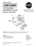
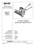
™
OWNER'S
MANUAL
MODEL NO.
45-03084
Universal Tow Behind Tiller
CAUTION:
Read Rules for
Safe Operation
and Instructions
Carefully
•
•
•
•
•
Assembly
Operation
Customer Responsibilities
Service and Adjustment
Repair Parts
the fastest way to purchase parts www.speedepart.com
Printed in U.S.A.
FORM NO. 40566 (05/09/08)
TABLE OF CONTENTS
SERVICE AND ADJUSTMENT.............................11-12
STORAGE.................................................................. 12
TROUBLESHOOTING................................................ 13
REPAIR PARTS.....................................................14-16
PARTS ORDERING/SERVICE.....................Rear Cover
SAFETY RULES........................................................... 3
ASSEMBLY................................................................4-5
OPERATION..............................................................6-8
MAINTENANCE......................................................9-10
This unit is equipped with an internal combustion engine
and should not be used on or near any unimproved forest
covered, brush covered, or grass covered land unless
the engine's exhaust system is equipped with a spark
arrester meeting applicable local or state laws (if any). If a
spark arrester is used, it should be maintained in effective
working order by the operator.
In the state of California the above is required by law
(Section 4442 of the California Public Resources Code).
Other states may have similar laws. Federal laws apply on
federal lands. A spark arrester muffler is available at your
nearest authorized engine service center.
2
3
ASSEMBLY
TO REMOVE UNIT FROM
CARTON
TO INSTALL THE TILLER
GAUGE WHEELS
• Cut from top to bottom all four corners of the carton
and lay panels flat. (See Fig. 1)
• Remove the lag screw that holds the floating hitch to
the packing skid.
• Disassemble and discard carton's wood top and side
supports.
• Remove four hex bolt, hex nuts and flat washer from
the hold down brackets at the rear of the carton.
• Remove and save the two Flat Washers and Cotter
Pins from the rear axle. Reuse when attaching gauge
wheels.
• Discard all other packing hardware and hold down
brackets.
• Assemble Gauge Wheels onto the Rear Axle with the
extended end of Hub facing inward. Secure with the
Flat Washers and Cotter Pins which you removed from
the axle during unpacking. (See fig. 2.)
FIG. 2
TO INSTALL THE TILLER TINE
ASSEMBLIES
• Attach the floating hitch to the tractor's draw bar.
(Refer to Operating Instructions on page 7.)
• Remove the preassembled 3/8" x 2" hex bolt and 3/8"
nylock nut from the L.H. Tine Assembly. Slide the tine
assembly onto the Transmission Axle on the left side
of the tiller and secure with the hex bolt and nylock nut.
(See fig. 3.) Repeat for the R.H. side.
FIG. 1
3/8" NYLOCK
NUT
• Right hand (RH) and left hand (LH) are determined
from the drivers position while seated on the tractor.
• We recommend that you remove the Mower Deck
before using the Tiller. Refer to your Tractor Owner's
Manual.
4
FIG. 3
ASSEMBLY
TO INSTALL (WHEEL)
WEIGHTS TO TILLER
NOTE: Weights are not furnished with the Tiller. 30 lb.
tractor wheel weights may be purchased to mount to the
Tiller if extra weight is required. (Refer to the Operation
section of this manual.)
• Remove two Carriage Bolts and Nuts from each Tine
Shield, located approximately 3-1/2" from the front
edge. See fig. 4.
• Place (Wheel) Weights on Tine Shield and secure with
long Bolts and Nuts furnished with the Weights. See
fig. 4.
FIG. 4
5
OPERATION
FIG. 5
RECOIL START HANDLE - used to start the engine
SAFETY SWITCH - prevents engine from starting while
tine clutch lever is engaged
THROTTLE CONTROL - controls engine speed
LIFT HANDLE - selects tilling or transport position by
moving gage wheels
FUEL SHUT OFF - shuts of fuel to engine
TINE CLUTCH LEVER - starts and stops tine rotation
CHOKE CONTROL - used when starting a cold engine
FLOATING HITCH - telescoping hitch limits shock loads
to tractor
DEPTH STAKE - controls tilling/cultivating depth
6
OPERATION
The operation of any tiller can result in foreign objects thrown into the eyes, which can
result in severe eye damage. Always wear safety glasses or eye shields before starting
your tiller and while tilling. We recommend a wide vision safety mask for over the
spectacles or standard safety glasses.
HOW TO USE YOUR TILLER
•
BEFORE STARTING YOUR TILLER
•
FILL THE ENGINE WITH OIL! Your tiller engine is
shipped without oil or gasoline. Add oil and gas as
instructed in the separate engine manual.
Repeat instructions in two preceding paragraphs until
engine fires. When engine starts, move choke control
gradually to RUN position.
Allow engine to warm up for a few minutes before
engaging tines.
ATTACHING TILLER TO TRACTOR
(See Fig. 6)
WARNING: Never fill fuel tank indoors, or
with the engine running, or while the engine
is hot. Do not smoke while filling tank.
•
•
•
STOPPING YOUR TILLER
TINES
• Raise tiller to transport position.
• Pull forward on tine clutch lever.
•
Rear wheel weights and tire chains can be used on
tractor if additional traction is required for tilling.
Place Tiller on ground level and back up tractor to it.
Slide Floating Hitch of Tiller onto the tractor drawbar
so that the hitch pin holes line up.
Insert hitch pin until it extends through bottom of
Floating Hitch. Insert hair cotter pin into hitch pin.
ENGINE (Refer to separate engine manual.)
• Move throttle control to "STOP" position.
• Turn shut off to "OFF" position.
• Never use choke to stop engine.
STARTING YOUR TILLER
(Refer to separate engine manual.)
CAUTION: The muffler and adjacent areas
are hot!
•
•
•
•
•
•
•
•
Check oil and gas in Tiller engine.
Attach spark plug wire to spark plug.
Pull forward on tine clutch lever to disengage tines.
A safety switch prevents engine from starting while
tines are engaged.
Turn shut off to "ON" position.
Move choke lever on engine to CHOKE position.
(A warm engine may not require choking.)
Move throttle control lever on engine to FAST
position.
Grasp starter handle and pull rope out slowly until
engine reaches start of compression cycle (rope will
pull slightly harder at this point). Let the rope rewind
slowly.
Pull rope with a rapid, continuous, full arm stroke.
Keep a firm grip on starter handle. Let rope rewind
slowly. Do not let starter handle snap back against
starter.
FIG. 6
BREAKING IN YOUR TILLER
Break-in your belts, pulleys and the control before you
actually begin tilling.
• Start engine with tiller attached to tractor in transport
position. Engage Tine Clutch Lever to start tine
rotation. Allow tines to rotate for five minutes.
• Check tine operation and adjust if necessary. See
"TINE OPERATION CHECK" in the Service and
Adjustments section of this manual.
7
OPERATION
TRANSPORTING YOUR TILLER
AROUND THE YARD
• Pull forward on lift handle until it locks in the up,
transport position.
AROUND TOWN
• Disconnect spark plug wire.
• Drain fuel tank.
• Transport in upright position to prevent oil leakage.
8
CUSTOMER RESPONSIBILITIES
Check Engine Oil Level
to 8
hrs
25
.
eve hrs.
ry s or
eas
50
on
h
eve rs.
ry s or
eas
on
1
ev0e0 hrs
ry s . or
eas
on
Yea
rly
Firs
t5
eac
fore
complete regular service.
Be
MAINTENANCE SCHEDULE
Fill in dates as you
hu
se
Refer to the engine manual for instructions on engine maintenance.
X
Change Engine Oil
X
Service air cleaner precleaner
X*
X**
Service air cleaner cartridge
X**
Replace spark plug
X
Clean cooling system
X**
Check valve clearance
Check for loose fasteners
Service Dates
X
X
Lubricate Tiller
X
Lubricate Tiller Transmission
X
*Change oil every 25 hours when operating the engine under heavy load or in high temperatures.
*Clean more often under dusty conditions or when airborne debris is present. Replace air cleaner parts, if very dirty.
9
CUSTOMER RESPONSIBILITIES
ENGINE MAINTENANCE
WARNING: Always stop engine and
disconnect spark plug wire before cleaning,
lubricating or before performing any repairs
or maintenance.
•
•
•
•
Check oil level before each use and every 8 hours.
Maintain engine oil as instructed in the separate
engine manual.
Service air cleaner every 25 hours under normal
conditions. Clean every few hours under extremely
dusty conditions. Poor engine performance and
flooding usually indicates that the air cleaner should
be serviced. To service the air cleaner, refer to the
separate engine manual.
Spark plug replacement is recommended every 100
hours or yearly. Check the engine manual for correct
plug type and gap specifications.
10
SERVICE AND ADJUSTMENTS
WARNING: Shut off (disengage) the Tine
Clutch Lever, the Tiller Engine and the Tractor
Engine before making any repairs.
TO REPLACE V-BELT
Replace V-belt if it has been damaged considerably from
slipping under heavy loads or if it show cracks or frayed
edges. Refer to figures 11 and 12.
IMPORTANT: Do not move or remove the belt guide.
If the position of the belt guide is accidentally altered,
return it to the correct setting (6-1/2" above the tine shield
support plate).
•
•
•
•
•
Remove the screw from the top of the belt guard.
Remove the hex nut from the rear of the guard.
Remove the belt guard to allow access to drive belt.
Disengage tine clutch lever and remove belt.
Reverse above procedures for installation of new belt.
FIG. 12
FIG. 11
11
SERVICE AND ADJUSTMENTS
SPARE TINE DRIVE BOLTS
WARNING: Shut off (disengage) the Tine
Clutch Lever, the Tiller Engine and the Tractor
Engine before making any repairs.
•
The Tiller drive components are protected from
damage by (shearable) Grade 5 hex bolts in the
Tine Assemblies. The hex bolts drive the tines and
hold them in the proper location. Should the Tine
Assemblies strike or pick up a large hidden object
or become jammed, the hex bolts will break and the
drive components will not be damaged.
•
Two extra tine hex bolts and nuts are included with
the tiller. They are located in the Tiller Stake Support
Bracket on the rear of the Tiller.
•
The tine hex bolts are designed to be loose fit. Do not
attempt to use a bolt or pin that is larger or harder
than the original Grade 5 hex bolts.
TINE CARE
•
For best results — Tine Blades should be kept
reasonably sharp. The Tine Blade can be sharpened
on a grinding wheel. Do not attempt to sharpen Tines
while they are mounted to Tiller.
STORAGE
•
Immediately prepare your tiller for storage at the end of
the season or if the unit will not be used for 30 days or
more.
•
CAUTION: Never store the tiller with
gasoline in the tank inside a building, where
fumes may reach an open flame or spark.
Allow the engine to cool before storing in
any enclosure.
•
•
ENGINE
•
Follow the instructions in the "Service & Storage"
section of the Engine Manual.
WARNING: Never cover Tiller while
engine and exhaust areas are still warm.
TILLER
•
•
•
Clean entire tiller (See "CLEANING" in the Customer
Responsibilities section of the manual).
Inspect and replace belts, if necessary (See
belt replacement instructions in the Service and
Adjustments section of this manual.
Lubricate as instructed in the Customer
Responsibilities section of this manual.
Be sure that all nuts, bolts and screws are securely
fastened. Inspect moving parts for damage, breakage
and wear. Replace if necessary.
Touch up all rusted or chipped paint surfaces; sand
lightly before painting.
If possible, store tiller indoors and cover it to protect
from dust and dirt.
Cover tiller with a suitable protective cover that does
not retain moisture. Do not use plastic. Plastic cannot
breathe, which allows condensation to form and will
cause your unit to rust.
12
TROUBLESHOOTING
Follow the instructions in the "Service & Storage" section of the
Engine Manual when performing any work on the Engine.
13
14
68
23
64
53
14
69
18
20
12
85
58
19
16
17
42
11
22
19 28
48
A
40
59
B
A
C
27
60
82
38
37
41
28
23
34
33
38
39
30
74
76
21
23
57
26
13
25
60
10
72
86
35
36
11
61 60
9
24
75
B
45
23
38
78
8
75
29
63
38
7
14
77
32
80
28
47
46
31
6
15
2
50
28
D
75
54
38
65
63
51
28
C
5 4 84
D
1
66
44
67
54
60
61
71
3
49
71
28
28
23
56
70
62
60
73
68
52
83
67
50
23
55
81
43
80
REPAIR PARTS FOR MODEL 45-03084 Universal Tow Behind Tiller
REPAIR PARTS FOR MODEL 45-03084 Universal Tow Behind Tiller
ref. part no. qty.
description
ref. part no. qty.
description
1
40993
1 Engine (49 State)
44
HA20094
1 Tine & Hub Assembly - RH
40997
1 Engine (California)
45
HA20088
1 Tine & Hub Assembly - LH
2
48346
1 Guide - Belt
46
43054
4 Bolt, 3/8-16 x 2"
3
43085
4 Bolt, 5/16-18 x 1-1/2" Hex Head
47
47600
1 Bolt, Hex 5/16-24 x 1"
4
HA115321
1 Set Screw, 5/16-18 x 5/16"
48
HA5236
1 Pin, Hitch
5
HA11154
1 Key, Square 1/4" x 2"
49
43062
1 Bolt, 3/8-16 x 1-1/2" Hex Head
6
HA20176
1 Pulley
50
HA20918
2 Wheel
7
48733
1 Nut, 1/2-12 Nylock Jam
51 R74780828 1 Bolt, 1/2-13 x 1-3/4" Hex Head
8
HA124934
1 Nut, 1/2-12 Hex Jam
52
HA20670
1 Pivot Axle Assembly
9
HA19860
1 Spring, Depth Extension
53
43350
8 Bolt, 3/8-16 x 1" Carriage
10
64282
1 Hitch Bracket Assembly
54
HA20725
2 Strap Frame Extension
11
43063
5 Bolt, 5/16-18 x 1" Hex Head
55
HA3433
2 Pin, Clevis
12
43064
9 Locknut, 5/16-18 Hex
56
HA20690
1 Stake, Drag
13
64343
1 Lift Handle Assembly
57
HA20932
2 Bracket - Wheel Weight Support
14
48840
3 Screw, Self-Tapping 1/4" x 1/2"
58
HA20940
1 Decal, Danger
15
43081
1 Washer, 5/16" Std. Wrt.
59
25830
1 Plate, Fender Support
16
HA20135
1 Ring, Retainer
60
47810
18 Nut, Hex 5/16-18 Nylock
17
HA20184
1 Pulley, Input
61
41576
5 Bolt - 3/8-16 x 1-3/4" Hex Head
18
HA20178
1 Bolt - Shoulder
62 R74760884 1 Bolt, 1/2-13 x 5-1/2" Hex Head
19
47189
6 Nut, Hex Nylock 1/4-20
63
44326
2 Bolt, 5/16-18 x 1" Carriage
20
24848
1 Clutch Rod
64
24849
1 Belt Guard (incl. #69)
21
HA23199
1 Switch, Safety Interlock
65
HA14306
1 Washer
22
24847
1 Lever, Clutch
66
HA20691
1 Strap-Frame Extension Brace
23
HA21362
19 Nut, Hex Nylock 3/8-16
67
712-3083
3 Nut, 1/2-13 Nylock
24
HA20170
1 Grip, Handle
68
HA20938
2 Decal, Danger
25 C-9M5732
2 Rivet, Pop
69
HA20942
1 Decal
26
HA20134
1 Belt Guide & Idler Mounting Bracket 70
HA5713
1 Spacer
27
HA9131
4 Screw, 5/16-18 x 3/4" Self Tap
71
HA15200
2 Washer
28
43661
11 Bolt, 1/4-20 x 1" Hex Head
72
712-0261
1 Nut, Hex 5/18-11 Nylock
29
HA20185
1 Key, Woodruff No. 61
73
HA7974
2 Spacer
30
24863
1 Cover, Drive
74
48278
1 Bolt, Hex 5/8-11 x 7-1/2"
31
HA20119
1 Transmission - Complete
75
43010
6 Pin - 1/8" x 1-1/4" Cotter
32
24843
1 Chassis, Left
76
HA20688
1 Rod - Lift
33
HA20186
1 Spring, Extension
77
HA19649
1 Anchor - Adjustment
34
24844
1 Chassis, Right
78 HA120396
5 Washer, 17/32" x 1-1/6" x .095" Flat
35
24846
1 Bracket, Idler
79 HA124934
1 Nut - 1/2-20 Hex Jam
36
HA11496
1 Pulley, Idler
80 HA456151
4 Washer, 13/16" x 1-1/2" x .134" Flat
37
HA20187
1 V-Belt
81
HA20481
2 Pin - Hair Cotter
38
43013
7 Nut, 1/4-20 Hex Lock
82
HA22594
1 Shield, Tine (LH)
39
64284
1 Module
83
HA22595
1 Shield, Tine (RH)
40
43182
4 Hex Bolt, 5/16-18 x 3/4"
84
43178
1 Nut, 1/4-20 Hex
41
HA20112
1 Rear Guard Assembly - LH
85
HA20692
1 Hitch Tube Assembly
42
714-0117
1 Pin - Hair Cotter 5/32"
86 R19212113 1 Washer, 5/8"
1
43
HA20113
1 Rear Guard Assembly - RH
40566
Owner's Manual
*Standard Hardware - Purchased Locally
the fastest way to purchase parts www.speedepart.com
15
REPAIR PARTS FOR MODEL 45-03084 Universal Tow Behind Tiller
ref.
1
2
3
4
5
6
7
8
9
10
11
12
13
14
15
16
17
18
19
20
21
22
23
24
part no.
HA20344
43064
HA20123
HA20122
43013
HA20120
HA20136
HA20127
HA20121
43866
HA20125
HA20124
HA20130
HA20129
HA20132
HA20128
HA20133
HA20131
HA20135
43012
HA20137
HA20145
HA20155
HA20138
qty.
2
8
2
2
17
1
1
1
1
15
2
2
1
4
1
1
1
1
1
2
4
1
2
3
description
Dust Cap
Locknut, 5/16-18 *
Flange & Bearing Assy
Gasket, Flange
Locknut, 1/4-20 Hex *
Drive Housing & Bearing Assy - LH
Gasket, Drive Housing
Tine Shaft Assy
Drive Housing & Bearing Assy - RH
Bolt, Hex 1/4-20 x 5/8" Grade 8
Washer, Felt
Seal, Rubber
Plug, Transmission Oil
Washer, Thrust
Chain Assembly #40
Chain Assembly #50
Input Shaft Assembly
Idler Shaft Assembly
Ring, Retainer 5/8" Dia. Shaft
Bolt - 1/4-20 x 3/4" Hex Head *
Bearing
Seal
Bearing, Flange
Cap, Bearing
*Standard Hardware - Purchased Locally
the fastest way to purchase parts www.speedepart.com
16
NOTES
17
NOTES
18
NOTES
19
the fastest way to purchase parts www.speedepart.com
© 2001 Agri-Fab, Inc.
REPAIR PARTS
Agri-Fab, Inc.
809 South Hamilton
Sullivan, IL. 61951
217-728-8388
www.agri-fab.com