1
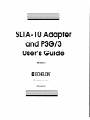
SLTA-10 Adapter
and PSG/3
User’s Guide
Revision 3
e ECHELON’
Corporation
078-0160-OlE
Echelon, LON, LonTalk, LonBuilder, NodeBuilder,
Neuron,
LonManager,
LONMARK, LonMaker, LONWORKS, 3120 and 3150
are registered trademarks of Echelon Corporation.
LonSupport
and LonWorld are trademarks of Echelon Corporation.
Other brand and product names are trademarks
trademarks of their respective holders.
or registered
Neuron Chips, Serial LonTalk Adapters, and other OEM Products
were not designed for use in equipment
or systems which involve
danger to human health or safety or a risk of property damage
and Echelon assumes no responsibility or liability for use of these
products in such applications.
Parts manufactured
by vendors other than Echelon and
referenced
in this document
have been described for illustrative
purposes only, and may not have been tested by Echelon. It is
the responsibility of the customer to determine the suitability of
these parts for each application.
ECHELON MAKES AND YOU RECEIVE NO WARRANTIES OR
CONDITIONS, EXPRESS, IMPLIED, STATUTORY OR IN ANY
COMMUNICATION
WITH YOU, AND ECHELON SPECIFICALLY
DISCLAIMS ANY IMPLIED WARRANTY OF MERCHANTABILITY OR
FITNESS FOR A PARTICULAR PURPOSE.
No part of this publication
may be reproduced,
stored in a
retrieval system, or transmitted,
in any form or by any means,
electronic,
mechanical,
photocopying,
recording,
or otherwise,
without the prior written permission of Echelon Corporation.
Printed in the United States of America.
Copyright 01996-2001 by Echelon Corporation.
Echelon Corporation
www.echelon.com
FCC NOTICE (for USA only)
Federal Communications
Commission
Radio Frequency
Interference
Statement
Warning: This equipment has been tested and found to comply with the limits for a Class B digital
device, pursuant to part 15 of the FCC Rules. These limits are designed to provide reasonable
protection against harmful interference in a residential installation. This equipment generates,
uses, and can radiate radio frequency energy and, if not installed and used in accordance with the
instructions, may cause harmful interference to radio communications. However, there is no
guarantee that interference will not occur in a particular installation. If this equipment does cause
harmful interference to radio or television reception, which can be determined by turning the
equipment off and on, the use is encouraged to try to correct the interference by one or more of the
following measures:
.
.
.
.
Reorient or relocate the receiving antenna.
Increase the separation between the equipment and receiver.
Connect the equipment into an outlet on a circuit different from that to which the receiver is
connected.
Consult the dealer or an experienced radio/TV technician for help.
Changes or modifications not expressly approved by Echelon Corporation could void the user’s
authority to operate the equipment.
Safety
UL
CSA (c-UL)
TW
CANADIAN
Listed, per UL-1950
Certified, per C22.2 no 950
Certified, per EN 60950
DOC NOTICE
This digital apparatus does not exceed the Class B limits for radio noise emissions from digital
apparatus set out in the Radio Interference Regulations of the Canadian Department of
Communications.
Le present appareil numerique n’emet pas de bruits radioelectriques depassant les limites
applicables aux appareils numeriques de la classe B prescrites dans le reglement sur la brouillage
radioelectrique edict6 par le Minis&e des Communications du Canada.
Preface
This document describes how to use the SLTA-10 Serial LonTalk@
Adapter to connect a host processor, with an EIA-232 (formerly RS232) serial interface, to a LONWORKS@’ network.
The connection to the
host processor can be made either directly or remotely through a pair
of modems.
SLTA-10 Adapter
User’s Guide
Content
This manual provides detailed information
SLTA-10 Adapter.
.
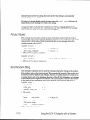
Chapter 1 introduces the SLTA-10 Adapter and provides a quick overview.
.
.
Chapter 2 describes the SLTA-10 Adapter hardware.
Chapter 3 describes how to attach an SLTA-10 Adapter.
Chapter 4 describes the configuration switches of the SLTA-10 Adapter.
.
Chapter 5 describes the software for the SLTA-10 NSI mode.
.
Chapter 6 describes the software for the SLTA-10 MIP mode.
.
Chapter 7 discusses using the Windows@ 95,TMWindows@ 98,TMand Windows NTTM
network driver and the SLTALink Manager software with the SLTA-10 NSI
mode.
Chapter 8 discusses using the DOS network driver with the SLTA-10 MIP mode.
Chapter 9 discusses creating an SLTA-10 MIP mode network driver for any host.
Chapter 10 describes initilization and installing as a node.
Chapter 11 discusses using an SLTA-10 Adapter with a modem and provides
specific instructions for setting up the SLTA-10 for remote dial-in access for
network monitoring and service operations.
Chapter 12 describes the DOS Host Connect Utility (HCU) for use with the
SLTA-10 MIP mode.
.
.
.
.
.
.
.
.
.
iv
about the hardware and software for the
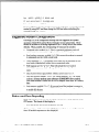
Chapter 13 explains how to use a programmable serial gateway.
Chapter 14 is a troubleshooting section.
Appendix A describes the Windows 3.1x DLL files for use with the SLTA-10
Adapter.
Preface
Related Manuals
The following Echelon documents are suggested reading for more information:
The LCA Object and Data Server Programmer’s Guide describes how to write a 32-bit
Windows host application and installation tool that can be used with the SLTA-10 NSI
mode.
The LONWORKS Host Application Programmer’s Guide describes how to write a host
application that can be used with the SLTA-10 MIP mode.
The LonBuildef
User’s Guide describes how to develop LONWORKS applications with
the LonBuilder Developer’s Workbench.
The NodeBuilder@ User’s Guide describes how to develop LONWORKS applications with
the NodeBuilder Development Tool.
Toshiba and Cypress have authored Neuron@ Chip databooks containing specifications
and literature that describe the architecture of the Neuron Chip.
Web Access
Engineering bulletins and data sheets supporting this product are available on the Echelon
Web site. General information regarding Echelon, its business, and its products also is
located on the site at http://www.echelon.com.
SLTA-10 Adapter
User’s Guide
V
vi
Preface
Contents
Preface
iv
Content
Related Manuals
Web Access
1
2
3
4
SLTA-10
V
V
Adapter
l-l
Overview
Introduction
Two Modes of Operation: SLTA-10 NSI and MIP Modes
SLTA-10 NSI Mode Features
SLTA-10 MIP Mode Versus the SLTA/2
The SLTA-10 Adapter Configurations
Software Availability
LNS Compatibility
TAP1 Compatibility
l-2
l-3
l-4
l-4
l-5
l-5
l-5
l-6
SLTA-10
2-1
Adapter
Hardware
Mechanical Description
Switches, Indicators, and Connectors
ESD Warning
Connecting Power
2-2
2-4
2-4
2-6
Cabling
3-1
and Connections
LONWORKS@
Network Connection
Attaching the SLTA-10 Adapter
Attaching the SLTA-10 Adapter to a PC
Attaching the SLTA-10 Adapter to a Modem
3-2
3-2
3-2
3-3
Hardware
4-1
Configuration
4-2
4-2
4-2
4-3
4-4
4-5
4-6
4-6
4-8
Configuring the SLTA-10 Adapter Hardware
Configuration Options
Interface Link Protocol Control (Switch1 / CFG3)
Modem Support (Switch2 / CFG2)
Network Disable (Switch3 / CFGl)
Serial Network Services Interface (Switch4 / NSI)
Autobaud (AB)
Serial Bit Rate (Switches[6..81/ Baud[B..Ol)
SLTA-10 Adapter Buffers
5 The SLTA-10
NSI Mode
SLTA-10 Adapter
User’s Guide
5-l
Software
SLTA-10 NSI Mode Software Overview
Windows 95198 and Windows NT Software Installation
Windows 95198 and Windows NT Software Installation
Procedure
Results
5-2
5-2
5-4
vii
6
7
The SLTA-10
MIP Mode
Software
SLTA-10 MIP Mode Software Overview
Installing the SLTA-10 MIP Mode Adapter Software
Installing the Windows 3.1x DLL Software
Other Drivers
6-2
6-2
6-5
6-5
Using the Windows
SLTALink
Manager
7-1
95/98 or NT Driver and
with SLTA-10 NSI Mode
Software Overview
Establishing a Communications Line for Dialing in to a Network
Establishing a Communications Line for Calls Dialed out to the PC
Establishing Remote and Local Network Sites
SLTALink Configuration Script Formats
Example
Name of Link
Remote Identifier
Link Type
Configuring the Modem Line
SLTA Password
Invoking an Application
Enabling a Callback
Configuration
Security
Timers
Modem Settings
Dial Directories
Auto-dialout Configuration
Diagnostics
The SLTALink Manager Programmatic Interface
Using the DOS “Stub” Driver
Characteristics of a Well-Designed System
Call Initiation
Dial-In to the Network Only
Dial-Out to the Remote PC Only
Dial-In / Dial-Out
Callback
Call Termination
Monitoring: Application Termination Strategy
Monitoring: Missing Messages after a Dial-Out
Monitoring: LNS Application Design Issues
Good Practices / Schemes that Work
I..
VIII
6-1
7-2
7-3
7-5
7-6
7-7
7-8
7-8
7-8
7-9
7-9
7-9
7-9
7-10
7-10
7-11
7-11
7-11
7-12
7-12
7-13
7-13
7-14
7-15
7-15
7-15
7-15
7-16
7-16
7-17
7-18
7-18
7-19
7-19
Preface
8
9
Using
the DOS Driver
with
SLTA-10
MIP
Mode
8-1
Installing the SLTA-10 MIP Mode Driver for DOS
Buffer Options
Serial Bit Rate Options
DOS Device Options
Timing Options
Network Interface Protocol Options
Calling the Network Driver from a Host Application
Using the SLTA-10 MIP Mode under Microsoft Windows 3.1x
8-2
8-2
8-3
8-4
8-5
8-5
8-8
8-10
Creating
9-1
an SLTA-10
MIP Mode
Driver
Purpose of the Network Driver
Example Network Drivers
Implementing an SLTA-10 MIP Mode Network Driver
Network Interface Protocol
Link Layer Protocol
ALERT/ACK Link Protocol
Buffered Link Protocol
Transport Layer Protocol
SLTA-10 Adapter Timing Data
Downlink Byte-to-Byte Receive Timeout
Uplink Message Life
ACK/NACK Receive Timeout
Uplink Timeout Message Retry Count
Session Layer Protocol
Downlink Buffer Request Protocol
Uplink Flow Control Protocol
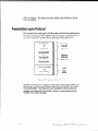
Presentation Layer Protocol
10 Initialization
and Installation
9-2
9-2
9-2
9-5
9-5
9-5
9-7
9-8
9-10
9-10
9-10
9-10
9-10
9-10
9-11
9-13
9-14
10-l
10-2
Initializing an SLTA-10 Adapter
10-3
Installing an SLTA-10 Adapter on a Network
Installing with LNS, the LonMaker for Windows Integration
10-3
Tool, or the LNS DDE Server
10-3
Installing with the LonBuilder Tool
Installing an SLTA-10 Adapter with LonManager API, the DOS-based
LonManager LonMaker for DOS Installation Tool, or the
10-4
LonManager DDE Server
SLTA- 10 Adapter
User’s Guide
ix
11 Using
the SLTA-10
Adapter
with
Overview
SLTA-10 Adapter Connection States
Command Set Assumptions
Translated Characters
DTE Connections
Network Management Messages
EEPROM String Pool Management
Product Query
Send Modem String
Modem Response Query
Connection Status Query
Install Directory Entry
Dial From Directory
Hang-up
Install Password
Install Modem Configuration String
Install Hangup String (MIP mode only)
Install Dial Prefer
Install Hangup Timer
Configure Modem
Request /Release SLTA
Clear EEPROM Pool
Install NVConnect (NSI mode only)
Install NSIConnect (NSI mode only)
Install CallbackEnable (NSI mode only)
Report SLTAEE (NSI mode only)
Modem Compatibility
V.90 Modems Tested with the SLTA-10
Remote Site Monitoring
Hardware Setup
Software Setup
SLTALink Manager
12 Using the Host Connect
Utility
with the SLTA-10 MIP Mode
HCU Usage
Theory of Operation
Usage Examples
Suggested Modem Configurations
Status and Error Reporting
a Modem
11-l
11-2
11-3
11-4
11-4
11-4
11-5
11-8
11-10
11-10
11-11
11-12
11-12
11-12
11-13
11-14
11-14
11-15
11-16
11-16
11-16
11-17
11-17
11-17
11-18
11-18
11-18
11-19
11-19
11-19
11-19
11-20
11-21
12-1
12-2
12-3
12-4
12-5
12-5
Preface
13 Using
a Programmable
Serial
13-1
Gateway
Creating a Serial Gateway
SLTA/PSG History
Programmable Serial Gateway Hardware Resources
Developing a PSG Application with the NodeBuilder
Development Tool
PSG Software Installation
PSGBOR.DTM
Firmware Library Support
Usage
Code Development and Debugging
PSG.LIB Functions
Advanced Applications
UART Registers
PROM/FLASH Specifications
Differences Between PSGI2 and PSG/3
Porting PSG /2 Code to PSG/3
14 Modem
A -
Windows
Introduction
ldv-close
ldvget-version
ldvioctl
ldv-open
ldv-read
ldv-write
13-4
13-4
13-5
13-5
13-6
13-7
13-8
13-10
13-11
13-11
13-11
13-12
14-1
Troubleshooting
Troubleshooting
SLTA-10 Adapter and Modem Do Not Answer or Pick Up
Modems Will Not Connect
SLTA-10 Adapter to Host Link Fails Completely
SLTA-10 Adapter to Host Link Fails Partially
SLTA-10 Adapter Sends Modem Configuration String,
But It Has No Effect
Appendix
13-2
13-2
13-3
DLL
Interface
Software
14-2
14-2
14-2
14-2
14-3
14-3
A-l
A-2
A-3
A-4
A-5
A-6
A-7
A-8
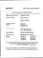
Declaration of Conformity
SLTA-10 Adapter
User’s Guide
xi
xii
Preface
1
SLTA- 10 Adapter
Overview
The SLTA-10 Serial LonTalk Adapter (Models 73351, 73352, 73353,
and 73354) is a network interface that enables any host processor with
an EIA-232 serial interface to connect to a LONWORKS network.
The
SLTA-10 Adapter extends the reach of LONWORKS technology to a
variety of hosts, including desktop, laptop, and palmtop PCs,
workstations,
embedded microprocessors,
and microcontrollers.
The SLTA-10 Adapter has two modes of operation: NSI and MIP
modes. The SLTA-10 NSI mode is compatible with LNS-based
applications.
The SLTA-10 MIP mode is compatible with legacy
applications based on the LonManager@ API or the HA host application
software. The SLTA-10 MIP mode is a replacement for the SLTA/2
Serial LonTalk Adapter. An externally accessible DIP switch
determines the mode of operation.
SLTA-10 Adapter
User’s Guide
l-l
Introduction
The SLTA-10 Adapter is the latest addition to the SLTA product family. It is an
EIA-232 (formerly RS-232) compatible serial device that allows any host with an
EIA-232 interface and proper software to communicate with a LONWORKS network.
An SLTA-10 Adapter enables the attached host to act as an application node on a
LONWORKS network. When used with a PC host and the LNS Developer’s Kit for
Windows software, the SLTA-10 Adapter can be used to build sophisticated network
management, monitoring, and control tools for LONWORKS networks. The SLTA-10
adapter also can be used with legacy host applications such as the LonManager
LonMaker installation tool, LonManager DDE Server, or applications based on the
LonManager API.
An SLTA-10 Adapter can be connected to the host through a pair of modems and the
telephone network, allowing the monitoring, control, or network management
computers to be remote from the network. The SLTA-10 Adapter can be set up to
answer incoming calls from a remote host. In addition, any node on the local network
can initiate a telephone call to a remote host computer. A new feature, available only
in the SLTA-10 NSI mode (see below), allows the SLTA-10 Adapter itself to initiate a
phone call to a remote host computer.
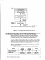
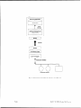
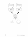
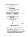
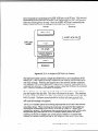
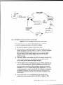
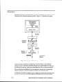
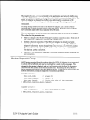
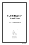
Figure 1.1 illustrates
a typical node based on an SLTA-10 Adapter. Chapter 11,
with a Modem, shows an SLTA-10 Adapter connected to
a host through the telephone network.
Using the SLTA-10 Adapter
I
l-2
SLTA-10 Adapter
Overview
Host
Host Application
LNS or LonManager
Software (optional)
Driver
Interface
Network Driver
EIA-232
Interface
SLTA-10
Network Adapter
.
Transceiver
Interface
Network
Interface
Figure 1 .l
LO/WORKS
SLTA-10 Adapter Node Architecture
Two Modes of Operation:
with Local Host
SLTA-10 NSI and MIP Modes
The SLTA-10 Adapter provides both the network services interface (NSI mode)
functionality for use with LNS-compliant applications, and network interface
functionality (MIP mode) for use with LonManager API-based applications.
There are two separate firmware images in the SLTA-10 Adapter. The two separate
images have different link layer protocols, different network drivers, different buffer
capacity, and different functionality. The two modes of operation are the SLTA-10
NSI mode and the SLTA-10 MIP mode. The mode of operation is controlled by an
externally accessible DIP switch that is read at power-up.
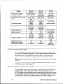
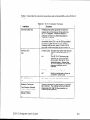
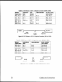
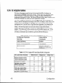
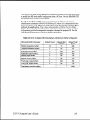
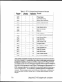
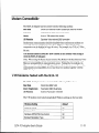
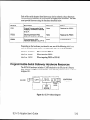
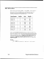
Table 1.1 illustrates the differences between the SLTA-10 NSI mode, the SLTA-10
MIP mode, and the SLTA/2.
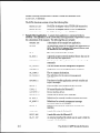
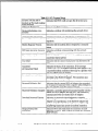
Table 1.1 SLTA-10 NSI and MIP Modes and SLTA/2 Feature Comparison
Feature
Supports LNS applications
Supports LonManager API
applications
Available drivers
SLTA-10 Adapter
User’s Guide
SLTA-10
NSI Mode
SLTA-IO
M/P Mode
YES
YES
NO
YES
NO
YES
Windows NT
Windows 95198
DOS, UNIX,
Windows 3.1x
DOS, UNIX,
Windows 3.1x
I
SLTN2
Feature
Software used to establish
connections via modems
Who initiates calls from a remote
network
Input power options
Configuration
Switches
Network Connector
Processor Input Clock
Ready to wall mount
Transceiver versions available
To attach to a modem
Supports sleep mode
Message Tag 15 available
Default Buffer Configuration
SLTA- 70 NSI Mode
SLTA-10
M/P Mode
SLTA-10
NSI Mode
SLTN2
SLTA-10 itself
or “Helper / Dialer”
node
9-30VAC or DC
or wall mount
supply
Externally
accessible
Color coded,
removable screw
terminals
(Weidmueller)
10 MHz
HCU (DOS
applicat/on with
source code)
“Helper / Dialer ”
node on network
HCU (DOS
application with
source code)
“Helper / Dialer ”
node on network
9-30VAC or DC
or wall mount
supply
Externally
accessible
Color coded,
removable screw
terminals
(Weidmueller)
IO MHz
wall mount supply
or internal battery
YES
TP/FT-1 0
TP/XF-78
TP/XF-1250
TPIRS-485
Special null
modem cable
YES
TP/FT- 10
TPIXF-78
TP/XF-1250
TPIRS-485
Special null
modem cable
NO
NO
See Chapter 4
NO
YES
See Chapter 4
j SLTALink Manager
(TAPI application)
j
1
Internally accessible
RJ45
5 MHz (1 OMHZ for
TP/XF-1250)
Bracket Required
TP/FT-1 0
TP/XF-78
TPIXF-1250
TPIRS-485
Internal jumper
chanae to become
DTE
YES
YES
See SLTAl2
j
documentation
Features
The most important new feature of the SLTA-10 NSI mode is the NSI functionality
for use with LNS-compliant applications. Other important features available only in
the SLTA-10 NSI mode include: SLTA-10 initiated dial-out, a Windows 95/98 driver, a
Windows NT driver, a high performance link layer protocol, and the SLTALink
Manager software. These features are not available in SLTA-10 MIP mode.
The improved hardware form factor applies to both modes of operation and is listed in
Table 1.1.
In SLTA-10 NSI mode, an SLTA-10 Adapter supports applications based on both the
LNS software and the LonManager API.
SLTA- 70 M/P Mode
Versus the SLTA/Z
In SLTA-10 MIP mode, the SLTA-10 Adapter is a replacement for the SLTAIB Serial
LonTalk Adapter, with an improved form factor. The network connector on the
SLTA-10 Adapter is the color-coded removable screw terminal (Weidmueller), instead
of the RJ45 used on the SLTA/2 Adapter. The SLTA-10 Adapter input power options
include 9-30VAC or DC, or a 9V wall mount supply. The SLTA-10 Adapter operates
at 10MHz for all transceiver types; the SLTAIB operates at 5MHz or lOMHz,
l-4
SLTA-10 Adapter
Overview
depending on transceiver type. In addition, the SLTA-10 configuration DIP switches
are externally accessible. The SLTA-10 enclosure has been improved to allow wall
mounting, without requiring a bracket.
The SLTA/2 and the SLTA-10 MIP mode use the same drivers and link layer protocol.
The SLTA- 70 Adapter
Configurations
The SLTA-10 Adapter is available with the following transceiver and power supply
options:
l
l
Software
Transceivers.
The SLTA-10 Adapter is available with four LONWORKS channel
options: TP/FT-10, TP/XF-78, TP/XF-1250, and TP-RS485. The FTT-1OA (78kbps,
free or bus topology), TPT/XF-78 (78kbps, bus topology) and TPT/XF-1250
(1.25Mbps, bus topology) transceivers use transformer-isolated, differential
transmission.
9V plug-in power supplies are available in U.S./Canada (Model
78010), U.K. (Model 78030), continental European (Model 78020), and Japanese
(Model 78030) configurations. Plug-in power supplies are sold separately.
Alternately, screw terminals are supplied for use with a 9 to 3OVACYDC power
sources.
Power supply.
A vailability
The SLTA-10 Adapter is not shipped with software.
Software for the SLTA-10 NSI mode is available with the LonMaker for Windows
Integration Tool (Model 370001, on the LNS Developer’s Kit for Windows CD (Model
34303), in the Connectivity Starter Kit (Model 58030-011, or from the Developer’s
Toolbox of the Echelon web site (http://www.echelon.com).
Software for the SLTA-10 MIP mode is distributed in the Connectivity Starter Kit
(Model 58030-01) and from the Developer’s Toolbox of the Echelon web site.
LNS Compatibility
When the SLTA-10 Adapter is connected directly to the PC host (i.e., no modems), the
SLTA-10 Adapter uses a direct connection. For a direct connection, the SLTA-10
Adapter behaves like any other NSI, such as the PCLTA-10 Adapter or the PCC-10
PC Card. In this case, an SLTA-10 Adapter may be used without issue with
applications based on any version of LNS starting with 1.0.
The SLTA-10 Adapter is also designed so that a PC host can be connected to the
network through a pair of modems and the telephone network. In this scenario, the
PC is a remote host. When the PC initiates the phone call to the SLTA-10 Adapter,
the remote host is said to “dial-in to the network”. When the SLTA-10 Adapter
initiates a call to the PC, the SLTA-10 is said to “dial-out to the remote host”. Once
the phone connection is established, the application running on the remote host can
perform network management, monitoring, or control activities.
SLTA-10 Adapter
User’s Guide
l-5
Applications based on LNS 1.0 or 1.01 do not have full functionality with respect to
the SLTA-10 Adapter and modems because LNS 1.0 and 1.01 have default system
behavior that is incompatible with using the SLTA-10 Adapter through modems. For
instance, an application based on LNS 1.0 and 1.01 terminates (i.e., shuts down) in a
manner that interferes with one the automatic dial-out initiation techniques. In LNS
1.0 or 1.01 when an LNS host application is terminated, all host network variables
and connections to these variables are removed from the LNS database. One way the
SLTA-10 Adapter can initiate a phone call, or automatically dial-out, is based on a
network variable update being sent to the SLTA-10 Adapter. Since the termination of
the application on the PC host results in the removal of all network variable
connections to the host, no network variable update can be sent to the SLTA-10
Adapter. Thus, one of the two mechanisms that support automatic dial-out is
unavailable.
LNS 1.0 and 1.01 have no special knowledge of whether the SLTA-10 Adapter is
remotely connected through a pair of modems. However, LNS versions starting with
1.5 and higher automatically detect that the SLTA-10 Adapter is remote at
commissioning. Using a remote SLTA-10 Adapter affects the default system behavior
by allowing the system to function as desired. Upon termination of an application
based on LNS 1.5 or higher, the LNS host API will determine if the NSI uses modems
and if there are any explicitly bound network variables on the host. If both of these
conditions are met, LNS does not remove the connections or host network variables.
In addition, LNS leaves the SLTA-10 Adapter configured. Thus, LNS 1.50 and later
versions fully support the SLTA-10 Adapter accessed through a modem configuration.
In summary, LNS 1.0 and higher versions fully support using the SLTA-10 Adapter
with modems. LNS 1.0 and 1.01 do not support the use of the SLTA-10 with modems,
although direct connect interfaces are supported.
Note: A remote (via modems) LNS Server requires a dedicated
SLTA-10 Adapter. Thus, some networks may require multiple SLTA-10
Adapters -one for the remote LNS Server and others to allow
access for other PCs.
TAPI Compatibility
The SLTALink Manager software uses TAP1 release 1.3 or higher. This is supported
in Windows NT 4.0 and higher, but not in Windows NT 3.51. Thus, Windows NT 3.51
does not support the use of the SLTA-10 Adapter with modems; however, Windows
NT 3.51 does support a direct connect interface.
l-6
SLTA-10 Adapter
Overview
2
SLTA- 10 Adapter
This chapter
SLTA-10 Adapter
provides
User’s Guide
a physical
description
Hardware
of the SLTA-10
Adapter.
2-l
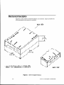
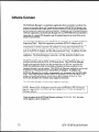
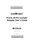
Mechanical
Description
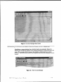
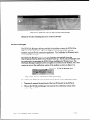
Figures 2.1 and 2.2 show the SLTA-10 Adapter in its enclosure. Figure 2.3 shows the
SLTA-10 Adapter board without an enclosure.
BACK VIEW
. ALL DIMENSIONS ARE IN INCHES WITH
EQUN. mm DIMENSIONS IN BRACKETS.
BACK VIEW
Figure 2.1 SLTA-10 Adapter Enclosure
2-2
SLTA-10 Adapter
Hardware
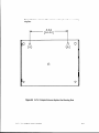
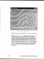
Figure 2.2 shows a 1:l view of the enclosure and may be used as a mounting
template.
3.42
[86.86]
-
P
7
0
0
0
0
0
Figure 2.2
SLTA-10 Adapter
*
SLTA-10 Adapter Enclosure Keyhole View Mounting Slots
User’s Guide
2-3
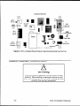
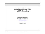
Component Side View
0
n
W)
Service I
Button
Wl)
(
Service
LED
Neuron@
3150@
Chip
(55)
EIA-232
Data Port
1
F
w 1
Config.
Switch
Block
(DW
lower Indicator
LED
Transceiver
Section
(53)
Power Input
(J2)
(Jl)
Power Input
Network
Connector
4
-
Figure 2.3
SLTA-10
0 ECHELON
1996
SLTA-10 Adapter Without Enclosure (Typical Component-Side
Switches, Indicators,
View from Top).
and Connectors
ESDWarning
This product contains components which are sensitive to static
electricity. Before installing or removing the network or serial
cables, touch earth ground with your hand to discharge any static
electricity which may have accumulated.
2-4
SLTA-10 Adapter
Hardware
Table 2.1 describes the external connections and switches/LEDs on the SLTA-10
Adapter.
Table 2.1 SLTA-10 Adapter Interfaces
Function
Interface
Service Button S2
Pressing this switch grounds the service
request pin on the Neuron Chip within the
SLTA-10 Adapter. While this switch is
pressed, the service LED should light to
maximum intensity.
If Switch 3 (the Network Disable switch) on
the switch block (Sl) is in the ON/up position
the service LED will light, but no service
message will be sent, even if the SLTA-10
has been configured after the last power up.
Service LED
DSl
(Yellow LED) Indicates that either the Service
Button is being pressed or, if
not:
on
The SLTA-10 firmware has
detected an unrecoverable
error and/or the SLTA-10 is
Applicationless.
Reboot the
SLTA-10 Adapter from another
network interface on the
channel.
blinking
Node is unconfigured.
Off
Node is configured or there is
no power. Check LED.
EIA-232 Data Port
Connector for the EIA-232 Serial I/O port.
J5
Standard DB9 female connection.
Network Connector
Orange connector for attachment to a twisted
pair channel. The mating socket provided is
Weidmtiller PN 128176 (two position) or
128186 (three position).
Two Position (Models
73351,73352,73353)
Three Position
(Model 73354)
Jl
SLTA-10 Adapter
User’s Guide
2-5
In tetface
Function
I
Unregulated
Black connector for the power input. The
mating plug (provided) is Weidmiiller PN
125911.
AC/DC Power Input
Two-Position
Unregulated
Female 2.1 mm inside diameter and 5.5 mm
outside diameter barrel input connector. For
use with Echelon power supplies, models
78010,78020,78030,
and 78040.
AC/DC Power Input
Barrel Connector
( J2
I
Power Indicator LED
(Green LED) Indicates presence of input
power to the SLTA-10 Adapter.
DS2
Connecting
Power
Once the SLTA-10 Adapter is physically attached to the desired channel, power must
be supplied via one of the power input connectors. The SLTA-10 Adapter may be
ordered with a plug-in power supply, or may be used with any 9 - 3OVACpDC supply.
Four plug-in power supply options are available for the SLTA-10 Adapter, depending
on the country in which the SLTA-10 Adapter is used: USA/Canada, United
Kingdom, Continental Europe, or Japan. The output voltage of these supplies is a
nominal +SVDC at 5OOmA. Power consumption is typically cl Watt, independent of
input voltage.
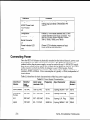
Table 2.2 describes the basic characteristics of the four power supply types.
Table 2.2 Power Supply Characteristics
Country
Region
or
Nominal
Input
Voltage
lnpu t range
nominal 210%
Frequency
Input Connector
Echelon
Model #
USA/Canada
120 VAC
108-l 32 VAC
60 Hz
2-prong, NEMA 1-15P
78010
Continental
Europe
230 VAC
207-253
VAC
50 Hz
2-prong, Euro Plug
78020
U.K.
230 VAC
207-253
VAC
50 Hz
3-prong, U.K. Plug
78030
Japan
100 VAC
90- 110VAC
50/60 Hz
2-prong, NEMA l-15P
78040
2-6
SLTA-10 Adapter
Hardware
Table 2.2 provides the specifications for power inputs to the SLTA-10 Adapter. The
barrel connector input, 52, is a standard female power plug with a 2.1 mm inside
diameter and 5.5 mm outside diameter, (LZR Electronics part number HP-114A,
Radio Shack catalog number 274-1569, or equal). A surge protector may be
required between the AC mains and the power supply as neither the power
supply nor the SLTA-10 Adapter include surge protection.
Power supply jack 53 provides screw terminals via a Weidmuller (PN 11261) input
connector (provided) for connection to a 9 - 3OVAUDC power supply.
Table 2.3 Two-Prong
Power
SLTA-10 Adapter Power Supply Requirements
Minimum
Nominal
Absolute
Maximum
Unregulated
+9 VDC
+12 VDC
+30 VDC
Unregulated
AC
9 VAC
24 VAC
30 VAC
When power is connected, the yellow service LED will briefly flash and the green
power indicator LED will turn on. Once an SLTA-10 Adapter is powered and
configured, the service LED will remain off unless the service request switch is
pressed.
Note: Do not attempt to power an SLTA-10 Adapter simultaneously
from JP2 and
JP3. Mechanical insertion of a connector into JP2 disables the input to JP3.
I
SLTA-10 Adapter
1
User’s Guide
2-7
2-8
SLTA-10 Adapter
Hardware
3
Cabling and Connections
This chapter
demonstrates how to attach the SLTA-10
LONWORKSnetwork, a PC, and a modem.
Adapter
to a
To connect an SLTA-10 Adapter to a modem, use a special null modem
cable. The SLTA-10 Null Modem Cable (Model 73380) is available for
purchase from Echelon. The cable specifications also have been
included in this chapter. Note that most off-the-shelf null modem
cables will not work in this configuration.
SLTA-10 Adapter
User’s Guide
3-l
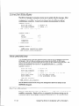
LONWORKSNetwork Connection
The SLTA-10 includes a removable screw terminal connector (Jl) for the twisted pair
LONWORKS network connection. The Jl should be connected as follows:
Polarity
Insensitive
s!zl
1
RS-485
Cable
-
2
Shield
Jl
Jl
Models 73351,73352,73353
Attaching
Model 73354
the SLTA- 10 Adapter
EIA-232 devices are configured as either Data Circuit-terminating
Equipment (DCE)
or as Data Terminal Equipment (DTE). A DCE device connects to a DTE device,
unless a null modem cable is used. Using a null modem cable, a DCE device connects
to a DCE device and a DTE device connects to a DTE device. The SLTA-10 Adapter
is a DCE device.
The standard configuration for a PC/AT EIA-282 serial I/O port is a DTE device. PCs
usually take the ‘terminal’ role in communications. Modems should always be DCE
devices. To connect an SLTA-10 Adapter to a PC, simply connect one end of the
serial cable to the SLTA-10 Adapter, and the other end of the cable to the PC’s serial
port. To connect an SLTA-10 Adapter to a modem, a special null modem cable must
be used. Note that most standard off-the-shelf null modem cables will not work in
this configuration.
Echelon offers the Model 73380 SLTA-10 Null Modem Cable, which is a DB-9 male to
DB-25 male null modem cable. This and other cables used with the SLTA-10 Adapter
are described in detail in the chapter.
Attaching
the SLTA-10 Adapter
to a PC
Most PC serial I/O ports have a g-pin male DB-9 connector, although some have a 25
pin male DB-25 connector. Most serial I/O ports are hard-wired as DTE devices.
If connecting to a PC or modem equipped with a DB-9 connector, then use a straightthrough cable with one end terminated with a DB-9 male connector and the other
end with a DB-9 female connector. Plug the male end into the SLTA-10 Adapter and
the female end into the serial I/O port.
3-2
Cabling
and Connections
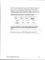
Table 3.1 PC DB-9 to DB-9 Connection
PC Connector
DB-9 Male
Cable DB-9
Female
Cable DB-9
Male
RxD
Pin 2
Pin 2
Pin 2
TxD
Pin 3
Pin 3
Pin 3
1 Pin 5
Pin 5
Pin 5
Signal Name
Signal Ground
I
I
I
I
DB9 Female
SLTA-10
WE)
PC (DTE)
DB-9
female end
DB-9
male end
Figure 3.1 DB-9 to DB-9 Connection
If using a PC or modem equipped with a DB-25 connector, then use a cable equipped
on one end with a DB-25 female connector and a DB-9 male connector on the other
end. Plug the male DB-9 connector into the SLTA-10 Adapter and the female DB-25
connector into the PC.
Table 3.2 PC 25Pin to DB-9 Connection
Signal Name
PC Connector
DB-25 Male
Cable DB-25
Female
Cable DB-9
Male
SLTA (DCE)
DB-9 Female
RxD
Pin 3
Pin 3
Pin 2
Pin 2
TxD
Pin 2
Pin 2
Pin 3
Pin 3
Signal Ground
Pin 7
Pin 7
Pin 5
Pin 5
T
PC (DTE)
DB-25
female end
DB-9
male end
SLTA-10
WE)
Figure 3.2 PC 25-Pin to DB-9 Connection
Attaching
the SLTA-10 Adapter
to a Modem
You must use a specific null modem cable to attach the SLTA-10 Adapter to a
modem. See the following tables and figures for the correct cable.
SLTA-10 Adapter
User’s Guide
3-3
Table 3.3 DCE Modem to SLTA-10 Adapter Connection
Modem
Signal Name
Cable DB-9
Male
Null
Modem
(DB-9 to DB-9)
SLTA-10 (DCE)
DB-9 Female
Cable DB9 Male
RxD-Pin
2
I Pin 2
1Pin 2-3
1Pin 3
1TxD-Pin
3
TxD-Pin
3
Pin 3
Pin 3-2
Pin 2
RxD-Pin
2
Pin 1
Pin l-4
Pin 4
DTR-Pin
4
DCD-Pin1
RTS-Pin
DTR-Pin
74
Pins 4 & 7
4.7-6
Pins
Pin 6
DSR-Pin
6
GND-Pin
5
Pin 5
Pin 5-5
Pin 5
GND-Pin
5
l-l
modem
DB-9
male end
SLTA-10
DB-9
male end
Null
Modem
Figure 3.3 DCE Modem to SLTA-10 Adapter Connection
Table 3.4 DCE Modem to SLTA-10 Adapter Connection
(DB-9 to DB-9)
(DB-25 to DB-9)
Modem
Signal Name
Cable DB-25
Male
Cable DB9 Male
SLTA-10 (DCE)
DB-9 Female
RxD-Pin
3
Pin 3
Pin 3
TxD-Pin
3
TxD-Pin
2
Pin 2
Pin 2
RxD-Pin
2
I DTR-Pin
4
DCD-Pin8
I Pin 8
DTR-Pin
RTS-Pin
20
4
Pins 20 & 4
Pin 6
DSR-Pin
6
GND-Pin
7
Pin 7
Pin 5
GND-Pin
5
l-l
modem
DB-25
male end
Null
Modem
SLTA-10
DB-9
male end
Figure 3.4 SLTA-10 Adapter Null Modem Cable (DB-25 to DB-9)
3-4
Cabling
and Connections
I
I
Hardware Configuration
This chapter
Adapter.
SLTA-10 Adapter
describes how to install
User’s Guide
and configure
an SLTA-10
4-l
Configuring
the SLTA- 10 Adapter
Hardware
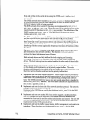
There are eight configuration switches on the SLTA-10 Adapter’s switch block (Sl).
These inputs are read by the SLTA-10 firmware to configure or enable features.
Figure 4.1 shows the factory default settings for the SLTA-10 Adapter. Changes to
the switch configurations will not occur until the power is cycled on the SLTA-10
Adapter. The switches are read immediately after a power reset.
The NSI switch selects between the legacy SLTA-10 MIP mode and a serial Network
Services Interface (NSI mode).
ON/up
OFF/down
Figure 4.1 SLTA-10 Adapter Default Switch Settings
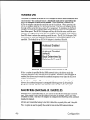
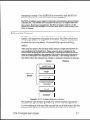
Configuration
Interface
Options
Link Protocol
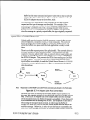
Control
(Switch 7 / CFG3)
Buffered Link Protocol
ALERT/ACK
Link Protocol
Figure 4.2 SLTA-10 Adapter Link Protocol Switch1 / CFG3
Switch1 / CFG3 controls the network interface link protocol used between the
SLTA-10 Adapter and a local host, when in MIP mode. For NSI mode, leave this
switch in the default position. Two link protocols are available for the SLTA-10 MIP
mode: the SLTA-10 Adapter ALERT/ACK link protocol and the buffered link protocol.
The ALERT/ACK link protocol is designed for host computers that cannot accept
asynchronously occurring streams of serial data at high speed. For example, a PC
4-2
Configuration
running DOS or Windows cannot guarantee receipt of all characters in an input
stream appearing back-to-back on a COM port . ALERT/ACK link protocol (down
position) is the default setting for the SLTA-10 Adapter. When the SLTA-10 Adapter
uses the ALERTlACK protocol and it wishes to send data to the host, it first sends a
single ALERT character (hex 01). The host then responds with an ALERT ACK
character (hex FE) to indicate its readiness to accept the rest of the data. The
ALERT/ACK protocol places timing requirements on the host, and if these timing
requirements are violated, a driver error occurs. After the host network driver has
sent the ALERT ACK character, it enters a tightly controlled loop for accepting the
remaining characters-usually
with interrupts disabled. If this option is enabled
(switch in down position), the ALERT/ACK protocol will also be used when the host
wishes to send data to the SLTA-10 Adapter.
The buffered link protocol (up position) is designed for host computers and applications
that can accept and buffer back-to-back serial data without losing characters. For
example, most real-time operating systems and / dev/ t ty drivers in UNIX systems
have this capability. In this case, the SLTA-10 Adapter simply sends the uplink
message without any handshake with the host. The SLTA-10 Adapter does not support
hardware handshake or XON/XOFF software flow control when directly attached to a
host. If the buffered link protocol option is enabled (up position), the buffered protocol
is also used when the host wishes to send data to the SLTA-10 Adapter. The buffered
link protocol should not be used when CFG2 is set to the Remote Host state
(up position).
See Buffered Link Protocol in Chapter 9 for additional application
restrictions when using the buffered link protocol.
Modem
Support
(Switch 2 / CFG2)
Remote Host (modem)
Local Host
(default)
Figure 4.3 SLTA-10 Adapter Host Switch2 / CFG2
Switch2 / CFG2 controls the use of the SLTA-10 Adapter with a modem. If the
SLTA-10 Adapter is connected directly to a host, then CFG2 should be set to the
Local Host state (down position). This is the SLTA-10 Adapter default. If the
SLTA-10 Adapter is connected to a modem, then CFG2 must be set to the Remote
Host state (up position) and CFG3 must be set to ALERTjACK (down position).
SLTA-10 Adapter
User’s Guide
4-3
Network
Disable (Switch3 / CFG 7)
Figure 4.4 SLTA-10 Adapter Network Switch 3 / CFGl
Switch 3 / CFGl enables (down position) or disables (up position) network
communications after reset. If disabled, the SLTA-10 Adapter will not be able to
communicate on the network after a reset until it receives an ~~FLUSH-CANCEL
command from the host.
The SLTA-10 Adapter prevents network communications by entering a FLUSH state.
This state causes the SLTA-10 Adapter to ignore all incoming network messages and
prevents all outgoing network messages, even service pin messages. In the disabled
state, if the service pin is pressed the service LED will light but no service message
will be sent. This FLUSH state is provided to prevent any other network management
tools from performing network management functions on the SLTA-10 Adapter
before the SLTA-10 Adapter’s host has a chance to perform any of its own network
management functions. This state is canceled with the niFLUSH_CANCEL command
from the host.
An SLTA-10 Adapter network driver may automatically enable network
communications when the SLTA-10 Adapter is opened. For example, by default, the
DOS network driver enables network communications by automatically sending the
niFLUSH_CANCEL command when the SLTA-10 Adapter is opened and when it
receives an uplink message from the SLTA-10 Adapter indicating that it has been
reset. If the host application needs to configure the SLTA-10 Adapter before enabling
network communications, the / z option on the DOS network driver command line
must be used to leave network communications disabled after the SLTA-10 Adapter
is opened. When the / z option is specified and CFGl is set to Network Disable On,
the host application itself must explicitly send the niFLUSH_CANCEL command after
reset.
The Windows 95198 or NT network drivers do not provide a / z option. When using
these network drivers, network communication will proceed without any action by
the host application if Switch3KFGl is in the Network Enable position. Otherwise, if
Switch3/CFGl is in the Network Disable On position, the host application must
explicitly send the niFlush_CANCEL
command.
4-4
Configuration
If CFGl is set to Network Enable (down position), the SLTA-10 Adapter will enable
network communications after a reset by going directly to the NORMAL state, thus
allowing communications without requiring the niFLUSH_CANCEL command.
If the SLTA-10 Adapter is used with a modem, and the application requires the
SLTA-10 Adapter to dial out to a host in response to a message from the network,
then CFGl must be set to Network Enabled.
If the modem is set to receive incoming calls only, then the host can disable the
FLUSH state after the connection is established, in which case CFGl can be set to
either position. Table 4.1 summarizes these options:
Table 4.1 SLTA-10 Adapter Network Disable Switch Configuration
Network
Disable
Input
Disabled
DOS Driver ’ R ’
Option
When SLTA-10 Adapter Enables
Network Communications
Specified
Host application command
Not specified (default)
Opening network driver
Don’t care
Immediately after reset
(up position)
Disabled
(up position)
Enabled
(default)
(down position)
Serial Network Services Interface (Switch4 / NSI)
NSI Mode Firmware
(default)
MIP Mode Firmware
Figure 4.5 SLTA-10 Adapter Firmware Switch 4 / NSI
The SLTA-10 Adapter has an SLTA-10 NSI-mode firmware switch which is Switch4
/ NSI. It is factory set in the up position for use of the SLTA-10 NSI mode
firmware. The down position is for the MIP mode firmware.
SLTA-10 Adapter
User’s Guide
4-5
Autobaud
(AB)
The switch (5) labeled AB on the SLTA-10 Adapter is used to select automatic baud
rate detection-the autobaud feature. Autobaud must not be used when the
SLTA-10 Adapter is used with a modem. When autobaud is enabled, the
SLTA-10 Adapter matches the serial bit rate of a local host. When powered, the
SLTA-10 Adapter looks for a ‘0’ byte from the host. The SLTA-10 Adapter cycles
through all the serial bit rates until a ‘0’ is recognized. To initialize the SLTA-10
Adapter, the host must transmit eight binary zeroes (or ASCII NULs), spaced at
least 50ms apart. The SLTA-10 Adapter will try all of its bit rates until the zero
character is recognized correctly, and will respond with an ALERT ACK character
(hex FE) when it selects the matching serial bit rate. The SLTA-10 Adapter DOS
network driver sends this sequence automatically if the autobaud option (/A) is
specified. The default for an SLTA-10 Adapter is Autobaud Disable.
4utobaud Enabled
r
(
Iutobaud Disabled
default)
E3aud Determined by
LCSwitches 6, 7, and 8
Figure 4.6 SLTA-10 Adapter Autobaud Switch 5 / AB
If the /A option is specified for the DOS network driver, the driver sends the
autobaud sequence every time the driver is opened. However, if the AB option is
enabled, the driver must re-send the autobaud sequence every time the SLTA-10
Adapter cycles power.
For the Windows 95198 or NT network driver, there is no /A option. Using these
drivers, the autobaud sequence is attempted following power up ifAutobaud
Enabled is selected, otherwise (the default) autobaud will not be attempted.
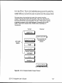
Serial Bit Rate (Switches(6..8) / BAUD(2..0))
Switches 6 to 8, named BAUD[2..01, are used to set the SLTA-10 Adapter serial bit
rate. This setting is only used if autobaud operation is disabled. There are eight
available bit rates. The SLTA-10 Adapter is configured for 38,400 bps with autobaud
disabled by default.
All data are transmitted
using 1 start bit, 8 data bits, no parity bits, and 1 stop bit.
The /B option is used to specify the serial bit rate to the DOS network driver.
Configuration
For the Windows 95198 or NT network driver, there is no /B option. When using
these drivers, the serial bit rate is configured using the SLTALink Manager as
explained in Chapter 7.
115,200
57,600
bps
bps
9600
bps
2400
bps
(default)
38,400 bps
1200 bps
19,200
300 bps
bps
IFigure 4.7 SLTA-10 Adapter Serial Baud Rate Switches 6, 7, and 8 / BAUD[2..0]
Table 4.2 SLTA-10 Adapter Autobaud Switch Configuration
Autobaud
Switch
BAUD
Switches
‘ /A ’ Option on
DOS Driver
‘/B ’ Option
Driver
down
Specifies actual
baud rate
Don’t care
Specifies actual serial bit
rate. Must match switchselected baud rate
Don’t care
Must be specified
Specifies actual baud rate
position
up
position
SLTA-10 Adapter
1
User’s Guide
I
on DOS
I
I
4-7
SLTA- 10 Adapter
Buffers
The types of messages passed between the host and the SLTA-10 Adapter are
determined by EEPROM configuration options. These options are described under
Network Interface Configuration
Options in Chapter 3 of the LONWORKS Host
Application
Programmer’s Guide. The Network Disable Option affects whether or not
the SLTA-10 Adapter can send and receive application messages.
The buffer configuration parameters can be changed at any time by sending Write
Memory network management messages to the SLTA-10 Adapter, either from a host
(using local network management messages) or over the network from a network
management tool. See the Neuron Chip Data Book, Appendix A, for details of the
data structures within the Neuron Chip that control the partitioning of RAM for
buffers. The following tables summarize the memory usage of the default
configurations for the respective two firmware versions resident on the SLTA-10
Adapter. The tables also list the maximum size of the buffer memory pool. If the
SLTA-10 Adapter is configured to use more bytes than are available in the pool, it
will behave erratically since the RAM is used by the SLTA-10 firmware.
Table 4.3 SLTA-10 Adapter Default EEPROM Configuration
Configuration
Parameters
Default
Setting
Initial State
Unconfigured
Explicit addressing
Enabled
Network variable processing
Host Selection
Program ID string
“SLTAl 0” (Mip Mode)
80-00-Ol -Ol -03-00-xx-3C
(NSI Mode)
I
Table 4.4 SLTA-10 Adapter MIP mode Default Buffer Configuration
M/P-mode
4-8
Buffer Parameter
Default
Count
Default Size
in Bvtes
Default Total
Bvtes
Configuration
The NODEUTIL node utility application, available on Echelon’s web site, can be used
to modify the MIP mode buffer configuration from a PC host. See the README.TXT
file included with NODEUTIL for details.
By default, the SLTA-10 NSI-mode program ID consists of 8 bytes of program
identification information (80-00-Ol-Ol-03-00-xx-3C, where ‘xx’ is determined by the
transceiver being used). The host application
must change this program ID to
indicate its application.
This is done automatically in LNS by the LCA Object
Server. If not using the LCA Object Server, the host application needs to send local
write-memory network management messages to change the program ID. See the
LNS Host API Programmer’s Guide for further information.
Table 4.5 SLTA-10 Adapter NSI-mode Default, and Minimum, Buffer Configuration
NSI-mode
IReceive
Buffer Parameter
Default
transaction
buffers
I
1 Transmit transaction
buffers
I
Default Size
in Bvtes
Count
16
Default Total
Bytes
I
13
I
I
28
I
208
3
255
765
Application output buffers
3
255
765
Network input buffers
2
66
132
Network output buffers
2
66
132
Priority app. output buffers
3
255
765
Priority net. output buffers
2
66
132
Application
input buffers
Total bytes used for buffers
SLTA-10 Adapter
User’s Guide
2955
4-9
4-10
Configuration
The SLTA- 10 NSI Mode Software
This chapter describes the Windows 95/98 or Windows NT software used
with the SLTA-10 NSI mode. This software is available with the
LonMaker for Windows Integration
Tool (Model 37000), in the
Connectivity
Starter Kit (Model 58030-Ol), as part of the LNS Developer’s
Kit for Windows (Model 34303) and on the Echelon web site
(www.echelon.com).
Skip this Chapter if you are using the SLTA-10 MIP mode.
SLTA-10 Adapter
User’s Guide
5-1
SLTA- 10 NSI Mode Software Overview
The SLTA-10 Adapter is not shipped with any software. The Windows NT driver and
SLTALink Manager software are available with the LonMaker for Windows
Integration Tool (Model 370001, in the Connectivity Starter Kit (Model 58030-011, as
part of the LNS Developer’s Kit for Windows (Model 34303) and on the Echelon web
site (www.echelon.com).
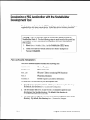
The SLTA-10 NSI mode set-up installs three pieces of software:
l
the SLTA-10 NSI mode Windows 95/98 or NT Driver,
.
a “stub” driver to run legacy DOS and Windows 3.1x applications, and
l
the SLTALink Manager software.
The SLTA-10 Adapter includes firmware that moves the upper layers of the LonTalk
Protocol from the Neuron Chip within an SLTA-10 Adapter and onto a host
processor. This firmware allows the SLTA-10 Adapter to be used by a host
application to send and receive LonTalk messages. The firmware in the SLTA-10
Adapter is loaded in ROM and cannot be reprogrammed.
Using the SLTA-10 NSI mode, the host application may be one of two types. The
first type of host application is an LNS-based application, developed with the LNS
Developer’s Kit for Windows. The second type of application is a legacy DOS or
Windows 3. lx application. Under Windows NT, these applications make use of the
“stub” driver declared in the conf ig . sys . OSfiles, which in turn accesses the
Windows NT driver. Under Windows 95198, Windows 3.1x applications should use
the DOS driver in conjunction with WLDV.DLL. Echelon does not support 32-bit
Windows applications that are not based on the LNS software accessing the Windows
95198 or NT drivers.
Windows 95/98 and
Windows NT Software
Installation
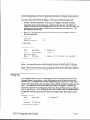
Procedure
Prior to installation, ensure that the computer is running the Windows 95/98 or NT
Operating System (Windows NT version 3.51 or higher for a direct connect interface;
Windows NT version 4.0 or higher for use with modems). The SLTA-10 software
cannot be installed from DOS, or a DOS shell, nor can it be installed on Windows 3.1
or Windows 3.11.
5-2
1.
Before installing the software, make sure that you have logged in as
Administrator (for Windows NT only).
2.
Close all open programs.
3.
Insert the installation
4.
Click the Start button on the Windows task bar and select the run
command. (If using with Windows NT 3.51: Within Program
Manager, choose the Run command from the File menu.)
diskette into the PC.
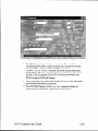
The SLTA-10 NSI Mode
Software
When prompted for a program name, enter the following:
5.
A:\SETUP.EXE
If necessary, replace A : with the drive letter which corresponds to the
drive containing the SLTA-10 NSI mode installation diskette.
6.
When prompted click the button marked ‘Next >“.
7.
When prompted for a destination directory, enter the desired
installation directory. By default this directory is c : \ 1onwor ks,
unless previous LONWORKS products have been installed and have
registered a different path in the Windows Registry. The path may
be modified using the “Browse” button.
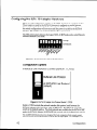
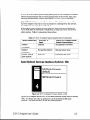
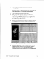
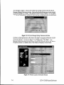
8.
The next screen presented is shown in figure 5.1. This will determine
the LONWORKS naming convention used for the SLTA-10 adapter.
Figure 5.1 LONWORKS Device Naming Convention
9.
Clicking the “Next” button concludes installation. At the prompt to
restart the computer, remove the SLTA-10 NSI mode installation
diskette and restart the computer. Note that the Windows
operating system will not recognize the SLTA-10 adapter until
the computer is restarted.
SLTA-10 Adapter
User’s Guide
5-3
Windows 95/98 and NT Software
Installation
Results
The Windows 95 and NT installation software loads a selection of new files
and updated Echelon files to different locations on the PC’s hard drive. The
function and location of these files can be found in readme. txt.
5-4
The SLTA-10 NSI Mode
Software
6
The SLTA- 10 MIP Mode Software
This chapter describes the SLTA-10 MIP mode software shipped
with the Connectivity
Starter Kit (Model 58030-01) and on the
Echelon web site at www.echelon.com.
This software is an updated
version of the SLTA/2 adapter software.
Echelon does not provide a 32-bit Windows
MIP mode.
driver for the SLTA-10
Skip this Chapter if you are using the SLTA-10 NSI mode.
SLTA-10 Adapter
User’s Guide
6-l
SLTA-10 MIP Mode Software Overview
The SLTA-10 Adapter is not shipped with any software. The SLTA-10 MIP mode
software and drivers are supplied in the Connectivity Starter Kit and must be
ordered separately. The software includes ANSI C source code for HA, a sample host
application for MS-DOS that can be used as a basis for a user-developed host
application on other host platforms. This application provides examples of sending
and receiving network variable messages, as well as allowing a node based on an
SLTA-10 Adapter to be installed and bound by a network management tool such as
the LonManager LonMaker Installation Tool or the LonBuilder network manager.
A network driver for DOS permits the SLTA-10 Adapter to be used with DOS
applications. Source code for a DOS network driver is provided as a basis for a userdeveloped network driver for other hosts or operating systems. On a separate
diskette, DLL software is provided to make it easier to use the network driver under
the Microsoft’ Windows 3.1x operating system.
An executable program and source code is also provided for a Host Connection Utility
(HCU), which may be used to initiate and terminate the host to SLTA-10 Adapter
connection when the SLTA-10 Adapter is used with a remote host. An example
written in Neuron C is also provided as a basis for user-developed nodes on a
LONWORKS network that need to initiate outgoing calls to a remote host.
The SLTA-10 Adapter includes firmware that moves the upper layers of the LonTalk
Protocol off the Neuron Chip within an SLTA-10 Adapter onto a host processor. This
firmware allows the SLTA-10 Adapter to be used by a host application to send and
receive LonTalk messages. The host application may be a custom application as
described in the LONWORKS Host Application Programmer’s Guide. The host
application may also be a network management or monitoring application based on
the LonManager API, LonManager LonMaker installation tool, or LonManager DDE
Server. The firmware in an SLTA-10 Adapter is fured in ROM and cannot be
reprogrammed.
Installing the SLTA- 10 MIP Mode Adapter
Software
The SLTA-10 Adapter software is supplied in the Connectivity Starter Kit as a
diskette. The SLTA-10 DOS driver operates under DOS, Windows 3.1x, and
Windows 95/98 operating systems. To install the SLTA-10 Adapter software, follow
these steps:
1. Place the diskette in one of the disk drives of your PC. This will typically be the
A: or B : drive. Under the Windows 95198 operating system, open a DOS console.
2. Start the automatic installation
AZINSTALL
procedure by entering:
[ENTER]
Substitute your disk drive name for the A : if you are using a different drive.
3. You will be asked to enter the name of your LONWORKS installation
directory.
C: \LONWORKS is the default.
6-2
The SLTA-10 MIP Mode
Software
The SLTA-10 Adapter software will be installed in the SLTA sub-directory of your
LONWORKS directory, with the exception of the DOS network driver LDVSLTA. SYS.
This file will be installed in the BIN sub-directory of your LONWORKS directory. To
install the DOS network driver into your CONFIG. SYS file, follow the instructions in
Chapter 8.
The SLTA directory will contain the following files:
l
l
Read-Me File. The README. TXT file includes a list of all the files on the
distribution disk, and also includes any updates to the documentation that
occurred since the SLTA-10 Adapter documentation was printed.
DOS Network Driver Sources. The SLTA-10 Adapter DOS network driver
source code is contained in the LDVSLTA directory. These files can be used as the
basis for creating drivers for hosts other than PCs running DOS (see also the
UNIX network driver sources). See Chapter 8 for a description of the SLTA-10
Adapter DOS network driver and Chapter 9 for a description of how to write an
SLTA-10 Adapter network driver for other hosts. See Chapter 4 of the
LONWORKS Host Application
Programmer’s Guide for a description of the
services that must be supplied by a LONWORKS network driver.
The source files to build the DOS driver are:
LDVSLTA.CFG
Configuration
MAKEFILE
Make file script for Borland C.
MDV-T1ME.C
Code to manage the PC timer.
External interface definitions for the timer handler.
MDV-T1ME.H
MSD-DRVR.H
Data structure and literal definitions.
DOS driver interface functions.
DOS driver interface and literal definitions.
MSD-EXEC.C
Main open, close, read, and write processing.
MSD-FRST.C
Module to be linked first in the network driver.
MSD-IRQC.ASM
MSD-RAW.C
Serial I/O interrupt procedure.
Module to be linked last in the network driver.
Direct serial I/O (modem) processing.
MSD-SEGD.ASM
Defines data segment register for driver.
MSD-SI0.C
PC/AT UART interface processing.
MSD-TXRX.C
Single byte link layer processing.
Defines PC/AT UART registers.
MSD-DEFS.H
MSDeD1FC.C
MSD-LAST.C
MSD-UART.H
l
file for Borland C.
External Interface Files. External interface files included for use by network
management tools are contained in the SLTA directory. External interface files
are included for the transceivers available for the SLTA-10 Adapter. See Binding
to a Host Node in Chapter 3 of the LONWORKS Host Application
Programmer’s
Guide for a description of how to use these files to bind to an SLTA-10 Adapter
node. Appendix B of the LONWORKS Host Application Programmer’s Guide
provides a detailed description of how to modify these files to incorporate network
variables and message tags. These interface files are provided in version 3
SLTA-10 Adapter
User’s Guide
6-3
formats. External interface files in version 3 format are contained in the
SLTA2\XIF-V3
directory.
The SLTA directories contain at least the following files:
l
NSLTA125.XIF
For SLTA-10 Adapter with a TP/XF-1250 transceiver.
NSLTA78K.XIF
For SLTA-10 Adapter with a TPKF-78 transceiver.
NSLTAFTl.XIF
For SLTA-10 Adapter with a TP/FT-10 transceiver.
Sample Host Application.
A sample host application is contained in the HA
directory. See Appendix A of the LONWORKS Host Application Programmer’s Guide
for a description of the example. The following files are included:
README.TXT
A description of the sample host application.
HA.EXE
An executable version of the sample host application for
DOS. The SLTA-10 Adapter DOS network driver must
be installed to run this application.
HA.C
The main program for the example.
NI-MSG.C
A general purpose network interface library that can be
used with any host application.
APPLCMDS.C
Functions to handle application layer network variable
commands
NI-CALLB.C
The host-bound network management dispatcher.
APPLMSG.H
Application message handler function prototypes.
HA-C0MN.H
The HA common declarations.
NI-CALLB.H
The definitions for the network management
dispatcher.
APPLMSG.C
Functions to handle application network variable and
explicit messages.
HAU1F.C
Command-line user interface for the example.
1OCTL.C
I/O control function for Microsoft C.
LDV1NTFC.C
Device interface driver.
LDV1NTFC.H
Include file for device driver interface.
NI-MSG.H
Definitions for network interface message structures.
NI-MGMT.H
Definitions for network management message
structures used by the example.
HAU1F.H
Definitions for the host application example user
interface.
MAKEFILE
A make file script for Borland C.
MSOFT.MAK
A make file script for Microsoft C.
HA-V3.XIF
An external interface file which may be used to bind the
example with LonBuilder.
The SLTA-10 MIP Mode
Software
l
l
HA-TEST.NC
A Neuron C program which may be loaded into a
Neuron emulator and bound to the sample host
application for testing.
D1SPLAY.H
A Neuron C include file to drive the Gizmo 2 I/O module
for the test example.
Host Connect Utility.
A sample host connection utility is contained in the HCU
directory, with source code. See Chapter 12 for details. The files supplied are:
HCU.EXE
Executable
file for the Host Connection
HCUJlA1N.C
The main C source program.
HCU.CFG
Configuration
MAKEFILE
Make file script for Borland
MSD-DRVR.H
Driver
file for Borland
definition
include
Utility.
C.
C.
file.
Neuron C Connection
Example.
A sample Neuron C program is contained in
the NC-APPS directory. This program shows how a node on a network connected
to the SLTA-10 Adapter can dial out and connect to a remote host computer. The
files supplied are:
DIALOUT.NC
Neuron C source program
SLTA-10 Adapter.
GIZSETUP.NC
An example Neuron C program for configuring the
SLTA-10 Adapter. Configures the EEPROM
directories of an SLTA-10 Adapter using the Gizmo 2
I/O module as the user interface.
SLTAJNM.H
Definitions
messages.
of SLTA-specific
to dial out with the
network
management
Installing the Windows 3.7x DLL Soffware
A second diskette, labeled “LONWORKS Network Driver Interface for Windows
3.1x”, contains the 16-bit Windows Dynamic Link Library (DLL) files. These files
may be used when developing a host application to run under Microsoft Windows
3.1x. The file WLDV . DLL should be copied to your Windows directory (typically
c : \WINDOWS). The files LDV. H and LON. H should be copied to a directory in the
include file search path of your C compiler. The file WLDV . LIB should be copied to a
directory in the library search path of your application linker. See Appendix A for
information
on using the Windows DLL.
0 ther Drivers
A UNIX network driver and source code for the SLTA-10 MIP mode is available
the Echelon web site (http://www.echelon.com).
Chapter
SLTA-10 Adapter
9 discusses creating
User’s Guide
on
a SLTA-10 MIP mode driver for any host.
6-5
6-6
The SLTA-10 MIP Mode
Software
7
Using the Windows 95/98 or NT
Driver and SLTALink Manager with
SLTA-10 NSI Mode
This chapter describes the SLTALink
Manager software, which
establishes and configures local and remote links from the host PC to
the SLTA-10 Adapter in NSI mode. A local link requires a direct
cable connection from the host PC to the SLTA-10. A remote link
requires a pair of modems: one attached to the SLTA-10 Adapter and
the other attached to the host PC. The SLTALink
Manager software
controls a remote SLTA-10 via a pair of modems through Windows’
Telephony Application
Programming
Interface (TAPI) services under
Windows 95/98 and NT 4.0 or later.
The SLTALink
Manager determines when a standard driver open
call in a host application requires dialing and handles these cases.
Thus, the host application does not need to know if the network
services interface is a local SLTA-10 or a remote SLTA-10 Adapter.
I
NOTE: Remote SLTA-10 Adapters cannot be used with Windows NT 3.51 because
Windows NT 3.51 does not include the 32-bit TAPI services used by the SLTALink
Manager software.
Skip this Chapter
SLTA-10 Adapter
User’s Guide
if you are using the SLTA-10
MIP mode.
7-l
Software Overview
The SLTALink Manager is a standalone application that can monitor a modem line,
answer an incoming phone call, associate the incoming call’s SLTA-10 Adapter (and
hence its network) with a LON device, and then launch a pre-determined
application
for that particular network or SLTA-10 Adapter. Combined with a properly designed
LNS host application, the SLTALink Manager lets a LONWORKS network establish a
connection to a remote PC through a pair of modems based on an event that occurs
locally to the network.
The SLTALink Manager provides a graphical user interface for creating, editing, and
diagnosing “links”. Each link represents a particular
SLTA-10 Adapter and its
network. A link identifies several important aspects of the set-up, including the type
of connection (a remote connection via modems or a local, direct connection), the
COM port, the SLTA-10 Remote Identifier (see below), the baud rate of the serial
port on the SLTA-10 Adapter, and the dial-in password, if any. In addition, the link
indicates if a security callback is required and may be associated with a host
application.
The link information
is stored in a .slO file, located by default in the
c:\lonworks\bin\sltalO
folder.
The SLTALink Manager application can associate a link with a LON device name
and then interface with the SLTA-10 NSI mode driver. The SLTALink Manager
handles automatically
dialing into the network from the PC host, providing the
ability for applications with no knowledge of modems or phone numbers to run
remotely through a pair of modems. The SLTALink Manager application can be used
to connect to or disconnect from a remote SLTA-10 Adapter. In addition, the
SLTALink Manager has a simple, programmatic way to interact with the SLTA-NSI
mode. This programmatic
interface allows an application to cause the SLTA-10 to
perform a number of functions, such as dial a phone number or hang up. The
SLTALink Manager also includes many diagnostic functions.
The SLTALink
Manager
includes
many diagnostic
functions.
NOTE: Remote SLTA-10 Adapters cannot be used with Windows NT 3.51 because
Windows NT 3.51 does not include the 3%bit TAPI services used by the SLTALink
Manager software.
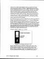
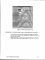
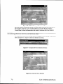
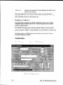
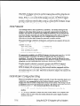
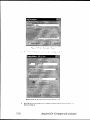
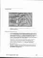
Upon invocation of the SLTALink Manager
screen appears, shown in figure 7.1.
7-2
software (SLTALINK
. EXE), the main
SLTA-10 NSI Mode
Software
Figure 7.1 SLTALink Manager Main Screen
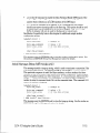
Establishing a Communications
Line for Dialing in to a Network
Establishing
a communications
line is the first task to be completed. Figure 7.2
displays the message that appears when Dialing Preferences is chosen from the Line
menu. This message will only appear when telephony information
has not been
provided. This case usually occurs if the computer has never been configured to use a
modem.
Figure 7.2
SLTA-10 Adapter
User’s Guide
First Time Use Message
7-3
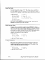
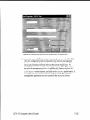
This message in figure 7.2 may not be visible due to being covered by the SLTALink
Manager Dialing Preferences window. Moving the Dialing Preferences window should
reveal the message-if
it exists. This leftmost window, shown in figure 7.3, will display
. . . for the “Dialing from:” indicator if there has been no dialing location created/chosen.
“~~~”
Figure 7.3 SLTALink Manager Dialing Preferences Window
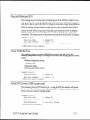
Clicking on Dialing Properties will bring-up the Windows Location Information
window
(figure 7.4) if the “Dialing from:” indicator reads “???“, or if TAP1 information
has been
previously entered - as shown in figure 7.3 as “Dialing from: The Office” - the
Windows Dialing Properties window (figure 7.5) will be displayed instead. The Dialing
Properties window is a tabbed subset of the Windows Telephony Control Panel.
Figure 7.4 Windows Location Information Window
7-4
SLTA-10 NSI Mode
Software
Figure 7.5 Windows Dialing Properties Window
Establishing a Communications
Line for Calls Dialed out to the PC
The next step is to select a line/modem to monitor for incoming calls. Figure 7.6
shows the Monitor Line window that is displayed when “Monitor for SLTA dial-in”
chosen from the Line menu.
Multiple
phone lines or modem can be monitored
calls) at the same time by the SLTALink
Manager
SLTA-10 Adapter
User’s Guide
(for receiving
software.
incoming
7-5
is
Figure 7.6 SLTALink Manager Monitor Line Window
The option list box will display the list of modems which have been set-up for use on
this computer. The list can be created/modified
by using the Windows Modem
Control Panel. Select the line/modem to be used for incoming calls, then click OK.
Establishing Remote and Local Network Sites
Choosing Select/Action from the Link menu will display a screen similar
shown in figure 7.7. Figure 7.8 shows the default local setup.
to the screen
Figure 7.7 Completed SLTALink Selection Window
Figure 7.8 Default SLTALink Selection
7-6
SLTA-10 NSI Mode
Software
Select “Local SLTA-10” and click Edit. This action will present a window allowing
the ability to customize the connection-including
changing it from Local to Remote,
or modifying the name.
SLTALink Configuration
Script formats
The SLTALInk Configuration
dialog can accept a script file for importing values to
the dialog’s user interface. Following this step, the configuration
values can then be
applied tot he SLTA-10 by clicking Apply.
Individual
configuration
items are processed on a line-by-line
basis. All values are not
required to be in the script file, and any duplicated assignments are simply overwritten.
Any line may start with a semi-colon, which is treated as a comment line.
length is limited to 80 characters. Assignments are structured as follows:
keyword=value
Line
(note that there are no blank spaces between the components).
Argument strings do not need to be quoted. Keywords are case-insensitive.
Edit the
script file as a simple text file with carriage returns and line feeds terminating
each
line.
The acceptable assignments
Keyword
Argument
Format
Password=password
Callback=switch
are:
string
Password: Up to 8 characters.
Callback enable: Either a ‘1’ or a ‘0’ for enabled
or disabled
value
HangupTimer=minutes
Description
value
Hangup timer: A number between 0 and 255.
Modemlnit=string
Modem initialization string: A string whose
length will be limited by the available EEPROM
pool space in the SLTA.
ModemDialPrefix=string
Modem dial prefix: A string whose length will be
limited by the available EEPROM pool space in
the SLTA.
DialDirl =string
to
Dial Directories 1 through 5: A string whose
length will be limited by the available EEPROM
pool space in the SLTA.
digits
NV Auto-connect: Either two digits, or not digits
if disabled. The first digit represents the starting
dial directory number and the second digit
represents the last dial directory.
DialDir5=string
NVConnect=two
SLTA-10 Adapter
User’s Guide
7-7
NSIConnect=two
ClearEEPool=switch
digits
value
NSI Auto-connect: either two digits, or no digits
if disabled. The first digit represents the starting
dial directory number, the second digit
represents the last dial directory number.
Either a ‘1’ or a ‘0’ to enable or disable clearing
of the EE pool before applying.
Example
. An SLTA-10 Configuration
bassword=BIG
DOG
Callback=1
HangupTimer=
GuardTimer=
ModemInit=ATEOVO&C1&D2SO=lMO
ModemDialPrefix=ATDT
DialDirl=14155557001
DialDir2=14155557002
DialDir3=12155557003
Dialdir4=
DialdirS=
NVConnect=
NVConnect=l
2
Script.
Name of link
The name of the link should be descriptive
connection and remote location.
enough to clearly define to users the
Remote Identifier
The Remote Identifier is used to identify a specific link when a dial-in to the
computer occurs. It represents the remote SLTA-10 Adapter in a 12-byte string of
characters or hexadecimal numbers. This value here should match the value stored
in the remote SLTA-10 Adapter. It can be entered here as a string in single quotes,
or as a series of hexadecimal numbers separated by dashes.
If this field is blank or all zeroes (oo-OO-OO-OO-OO-~~-~O-OO-OO-OO-OO-OO)
then the Remote Identifier
will be captured
and stored here the next time
this connection
is made.
If this field is all FFs (FF-FF-FF-FF-FF-FF-FF-FF-FF-FF-FF-FF)
then any
The identifier
will not be stored on the
Remote Identifier
will be accepted.
PC. This is known as the wildcard
Remote Identifier.
The question
mark
(?) is also accepted as the wildcard
Remote Identifier.
The SLTALink
Manager
software
translates
“?” to all FFS.
The Update Identifier checkbox indicates that the remote identifier will be read from
the SLTA-10 Adapter by the SLTALink Manager and the new value will be stored in
the .slO file the next time this link is used.
7-8
SLTA-10 NSI Mode
Software
The SLTALink Manager software allows a user to create two links with different
names but the same Remote Identifier.
However, when a network dials-out to a PC
with multiple links each with the Remote Identifier, the user has no control over
which link is selected, which could result in undesired behavior.
Link Type
The type of link specifies whether the SLTA-10 is directly connected to the PC
(Local), or if the SLTA-10 is at a different location and must be accessed via a set of
modems (Remote).
Configuring the Modem Line
Clicking on “Configure Line” will cause the selected modem’s property window to
appear. The property window will reflect the options available to the driver of the
modem such as volume control and dial-tone detection.
TAP1 services will handle the structuring
Information
(see figure 7.4).
of the call based on the Location
SLTA Password
The Password box allows the user to enter the password for a remote SLTA-10
Adapter. Up to eight characters may be entered. If entered, the password will be
sent to the remote SLTA-10 adapter when a connection is made.
The password
is not encrypted
when
stored
on the host computer.
Invoking an Application
The SLTALink Manager provides a space to enter the startup application for this
link. This may be a full executable path name, or the name of an application that
can be found in the system’s search path. Command line arguments may also added
- including the special macros for link connection variables:
%LINKNAME%
Expands to the name of the link, enclosed in quotes.
%DEVNAME%
Expands to the device name used by LONWORKS 32-bit
applications to access the logical device. This serves the same
purpose as %DOSNAME% does for DOS.
%NSSNAME%
Expands to the device name used by LonWorks
for SLTA-10s this will be “SLTALONn”.
%DOSNAME%
Expands to the DOS device name for the logical device, provided the
virtual device driver (VDD) is installed, which would be “LONn”.
%ID%
Expands to the remote identifier.
This is expressed as either a
quoted ASCII string, or as a series of hexadecimal numbers if the
identifier contains non-ASCII data.
SLTA-10 Adapter
User’s Guide
LNS application,
7-9
%RESULT%
Expands to an unquoted word that represents
reason of the connection.
the success or fail
The startup application will be launched when a dial-in occurs for this link, or
optionally, when a manual connection is made to the link. It will not start up if the
link is connected to due to an “auto-connect” case.
Enabling a Callback
If a remote SLTA-10 adapter has callback enabled then it will expect a callback
command whenever someone dials in to it. Check the Enable box if you need to
enable the callback feature.
The callback command includes a directory index that points to a phone number
stored in the remote SLTA-10 adapter. If callback is enabled then one of the remote
directory numbers (“Address 1” though “Address 5”) can be selected to be used to call
the host back.
See Characteristics
of a Well-Designed
successfully implement callback.
System below for a description
of how to
Configuration
Use the following
screen to configure
your SLTA-10 Adapter.
Figure 7.9 Configuration
7-10
Screen
SLTA-10 NSI Mode
Software
Security
Password
The SLTA Adapter may be configured to accept incoming calls and connect the
network to the host. Incoming callers may be required to provide a password before
the SLTA adapter will connect them to the network.
Enable
Callback
Check this box if you need to enable callback.
If a remote SLTA has callback enabled then it will expect a callback command
whenever someone dials in to it. The callback command includes a directory index
that points to a phone number stored in the remote SLTA.
Timers
Hangup
Timer, minutes
Provides a space to enter a hangup timer value for the SLTA. This must be within
the range of O-255, for 0 (disabled) to 255 minutes.
The hangup timer controls how many minutes
SLTA hangs up (disconnects the modem).
of inactivity
must pass before the
Guard Time, seconds
Provides a space to enter a guard time value for the SLTA, in seconds. This must be
within the range of O-255.
The guard timer controls how long to wait before attempting
for the auto-connect case.
to dial the next number
Modem Settings
Initialization
String
Provides a space to enter a modem initialization
/configuration
string for the SLTA.
This string is sent to the modem whenever the SLTA is reset and it is not currently
connected. Special characters may be embedded in the string:
!
Causes a carriage return
to be sent.
Causes a 500ms pause.
The carriage return
is not required
at the end of the string.
Dial Prefix
Provides a space to enter a modem dial prefer for the SLTA. This controls the
characters sent to the modem before the actual phone number is sent. The default is
“ATDT” for tone dialing.
SLTA-10 Adapter
User’s Guide
7-l 1
!
Causes a carriage return
to be sent.
Causes a 500ms pause.
The carriage return
is not required
at the end of the string.
Clear EE Pool on Apply
Check this box to clear the SLTA’s EEPROM pool before applying the configuration.
This will force the clearing and re-programming
of the strings that use the EEPROM
pool: The Modem Initialization
and Dial Prefer strings, and the Dial Directories. If
not checked then only the SLTA’s strings that have been changed will be updated.
Use this feature if you are increasing
another in one step.
the size of one string and decreasing
the size of
Dial Directories
Provides a space to enter the dialout directory numbers, as strings.
directory entry to edit, simply select one of the buttons above.
!
Causes a carriage return
To chose which
to be sent.
Causes a 500ms pause.
The carriage return
Auto-da/out
is not required
at the end of the string.
Configuration
NV Connect
Check this box to enable the Network Variable update auto-connect feature. When
enabled, the SLTA will attempt to connect to a remote host whenever the SLTA is
not connected and a non-broadcast host-bound NV update message is pending.
The SLTA starts with the directory number first specified on the right. If this
attempt fails then the next directory number is used, until the last directory number
has been used. To use a single number simply specify the same directory number in
both fields.
N$I Connect
Check this box to enable the Network Services (NSI) auto-connect feature. When
enabled, the SLTA will attempt to connect to a remote host whenever the SLTA is
not connected and a host-bound NSI message is pending.
The SLTA starts with the directory number first specified on the right. If this
attempt fails then the next directory number is used, until the last directory number
has been used. To use a single number simply specify the same directory number in
both fields.
I
7-12
SLTA-10 NSI Mode
Software
Diagnostics
A number of Diagnostic and testing services are provided via the Diagnostic Screen,
accessed through the Devices menu (see figure 7.10). The Test button retrieves
status and error counts from the SLTA-10 Adapter. The Service button will cause
the SLTA-10 Adapter to broadcast a service pin message on the network. The reset
button causes a reset of the Neuron Chip in the SLTA-10 Adapter, but does not clear
the Neuron Chip’s system image.
Some buttons
are left for future
releases of additional
features.
Figure 7.10 Diagnostic Screen
The SLTALink Manager
Programmatic
Interface
SLTALINK . EXE executes as a single process. If you try and run another copy of it, it
will defer itself to the original process. However, command line arguments may be
passed in this manner which will direct the existing process to perform certain types
of tasks. These command line options are:
~Linknarnew
A link name is required for all actions. If the link name alone
is passed then that link will be connected to. It must be
enclosed in double quotes, since the link name can have
embedded spaces.
C:\lonworks\bin\sltalink.exe
SLTA-10 Adapter
User’s Guide
"Remote"
7-13
This causes the specified link to be disconnected.
/D
C:\lonworks\bin\sltalink.exe
/#
Ymmber”
"Remote"
/D
This overrides the phone number for the link. If you have
checked the “Use Country Code and Area Code” option for
this link then the number must be in the ‘canonical’ format
without a ‘+’ sign and enclosed in double quotes. A canonical
number is defined as a country code followed by a space,
followed by an area code or city code enclosed in parenthesis,
followed by a space and the rest of the phone number. TAP1
will take this and decide how to translate it before performs
the dial-out, based on your dialing preferences. Even if the
call is local you should include the area code / city code. This
is the same format as the number that appears in the link
selection dialog under the Port/Number
column.
Example: “1 (BOO) 5551213”
If you have not checked the “Use Country Code and Area
Code” option then the number will be used un-translated
for
dial-out. In this case you probably won’t specify a canonical
number.
C:\lonworks\bin\sltalink.exe
/P
“passwdM
"Remote"
include
555 1213"
This overrides the password for the link. It must be enclosed
in double quotes.
C:\lonworks\bin\sltalink.exe
Always
/# "1 (650)
"Remote"
/P
"passwd"
a space between each element of the command line arguments.
Using the DOS “Stub” Driver
The DOS stub driver, which is added as part of the install, allows DOS and Windows
3.1x applications to run on top of the SLTA-10 drivers for Windows 95/98 and NT.
The following line is required in the CONFIG. SYS or CONFIG. NT file that is loaded on
startup:
DEVICE=%SystemRoot%\system32\PCLTDOS.SYS
This makes the device ‘LONn’ available
/Dn
for DOS applications.
When LONn is opened by an application and the SLTALink Manager has been
configured to associate LONn. with a particular link, the SLTALink Manager will
auto-connect to the SLTA-10 Adapter locally or remotely. That is, the SLTALink
Manager automatically
dials-in to the network defined by the link if required.
7-14
SLTA-10 NSI Mode
Software
Characteristics
of a Well-Designed
System
Well understood strategies used with the SLTA-10 Adapter and the SLTALink
Manager for the following system functions are essential for reliable system design:
Call Initiation,
Call Termination,
and Monitoring.
Call lnitia tion
The four scenarios for call initiation
are: dial-in
remote PC only, dial-in / dial-out, and callback.
to the network
only, dial-out
to the
Dial-In to the Network Only
In the most straight-forward
case, a user launches an application.
The application
opens the driver, which is associated with a particular link. The SLTALink Manager
application dials the phone number in the link (or the phone number the application
passes down to the SLTALink Manager perhaps to a generic link) and establishes the
connection. Similarly, the user could select the link from within the SLTALink
Manager and cause a manual connection. At this point, either the SLTALink
Manager would launch the pre-determined
application from the information
stored in
the link file or the user could manually launch the application.
In all of these cases,
the user is assumed to initiate the call. The user could be a human operator or
another application that initiates a dial-in based on a clock, for example.
For the dial-in only scenario, the system strategy issues primarily have to do with
associating the link or phone number with the application.
Where there are only one
or two links, this is very easy. When one PC host can be connected to many different
networks, we offer two standard solutions. The first is to have the user navigate the
SLTALink Manager’s GUI. Under the Link menu, the Select item lists
approximately
40 links (of the 1000 possible). The second solution is a monitoring
application that programmatically
interacts with the SLTALink Manager to send
down the appropriate phone number, perhaps to a generic out-going link.
Dial-Out to the Remote PC Only
The three common approaches for initiating
a dial-out are: sending a network
variable update to the SLTA-10 Adapter, sending an AddMyNSI message to the
SLTA-10 Adapter, or sending an explicit message from a “Helper/Dialer”
node on the
network.
In the first case, the remote host application needs to have an explicitly-bound
input
network variable and the SLTA-10 Adapter’s NSI mode EEPROM must be configured
correctly. See the configuration
section in this chapter or go to Chapter 11 for more
information
on configuring the SLTA-10’s EEPROM. See also Call Termination
below.
In the second case, the remote host PC is assumed to have the NSS engine and a
second NSI on the network (perhaps a service technician with a laptop running a
PCC-10 card) is required to send the AddMyNSI message. Also, SLTA-10 Adapter’s
NSI mode EEPROM must be configured correctly.
SLTA-10 Adapter
User’s Guide
7-15
In the third case, a custom Neuron
Chip application
must be written.
All three cases could be used with the same SLTA-10 Adapter.
In the dial-out only case, besides the call initiation,
the SLTALink Manager must be
able to launch the appropriate application - with the correct database and device
driver name. One system solution is to create a separate link for each SLTA-10
Adapter. Each link then stores the Remote Identifier of its SLTA-10 Adapter after
the first connection. Upon connection, the appropriate application and command line
arguments stored in the link get launched. A second viable approach is to create a
generic link that uses the wild card as a Remote Identifier to launch a generic
application using command line arguments to specify the appropriate network or
database and device driver name. These arguments are available and described
above under Invoking an Application.
Note: if the device driver information
used in the application
does not
match the device driver name being used by the link, the newly launched
application
can open a second device driver - which may result in an
attempt to dial-in to the network.
Since the modem is still presumably
in
use with the original
dial-out
call to the host PC, the second call will fail.
The result is a system-level
failure.
Dial-In / Dial-Out
These scenarios are the combinations and permutations
of the above. However, it
needs to be pointed out that not all dial-in strategies can co-exist with all dial-out
strategies. For example, if the dial-out strategy involves having the SLTALink
Manager match the incoming call to the wild card Remote Identifier
and if the dial-in
strategy requires a separate link for each SLTA-10 Remote Identifier,
then it is
possible that a call initiated from the network will be received by the SLTALink
Manager and will be matched with the link created for the dial-in case. The correct
application may not be launched and a system-level
failure may occur.
Callback
The SLTA-10 Adapter callback functionality
works as follows: A call is initiated from
some remote PC to an SLTA-10 Adapter on a network, which must have its NSI
mode EEPROM configured to require callback. The SLTA-10 Adapter answers; the
remote PC identifies to the SLTA-10 Adapter one of the SLTA-10 Adapters directory
entries to use for the callback. An SLTA-10 configured to require a callback will not
accept any other direction from the host at this time. The original call is terminated,
and the SLTA-10 Adapter calls the phone number indicated in its directory. Note:
this does NOT need to be the phone number of the original remote PC that initiated
the call. Typically, the SLTALink Manager on the remote host dialed answers the
call and launches the appropriate application.
Several possible system-level
l
l
7-16
failures
include:
The original remote host expects to receive the callback, but the directory
reflects the phone number of another remote host.
index
The original remote host application opens an LNS database and initiates the
first call. The callback is directed back to the original remote host PC. The
SLTA-10 NSI Mode
Software
SLTALink Manager on this PC receives the callback just like any other normal
dial-out call and launches the application contained in the link. At this point
there may be two copies of the application open. Depending on sharing
configuration,
the second application may fail because appropriate LNS database
in already opened.
To prevent these failures, Echelon recommends that the initial call should either be a
manual connection from within the SLTALink Manager or the initial call should
originate from a “dummy” application that terminates itself without opening the LNS
databases.
Call Termination
The four scenarios for call termination
include: termination
of the host application,
application controlled hang-up, a manual disconnect in the SLTALink Manager, and
time-out. In all of these cases, the important system-level issues involve making sure
that the termination
strategy is compatible with the call initiation
strategy.
The behavior of an application at termination
is not always known. By default,
applications based on the Object Server of LNS 1.5 and higher should exhibit two
types of behavior. First, if the interface adapter is an SLTA-10 Adapter in NSI
modem using modems and there are explicitly bound network variables to the host
application, then at the LNS application’s termination
the host network variables
and their connections should not be removed from the LNS database. This behavior
facilitates the use of the first case described under Dial-Out to the Remote PC Only
where a network variable update addressed to the SLTA-10 Adapter’s NSI mode
results in a call being initiated.
Second, if the interface adapter is not an SLTA-10
Adapter in NSI modem using modems or there are no explicitly-bound
network
variables to the host application, then at the LNS application’s termination,
any host
network variables and their connections are removed from the LNS database and the
other nodes in the network. In addition, if the interface does not host the LNS
database, upon termination
of the LNS application the interface is deconfigured.
The second behavior described would be desirable in the event that multiple remote
host PCs needed to be able to dial-in to the same network. As long as no explicitlybound network variables were left when the host applications terminated, then
several remote PCs could share one SLTA-10 Adapter. Note: this assumes that the
LNS Server exists somewhere on the network and is not located on one of the remote
PCs sharing the single SLTA-10 Adapter.
Both an application controlled hang-up (using the SLTALINK . EXE programmatic
interface) and a manual disconnect in the SLTALink Manager will terminate the
phone call; however, neither results in the termination
of the host application.
In
these scenarios the host application remains running as the call can be re-established
by the host application itself, by a manual connect in the SLTALink Manager, or a
dial-out initiated on the network. The disadvantage of these system solutions is that
they do not scale well to monitoring multiple networks on one PC. The result is
many applications continually
and concurrently
running on the same PC. Also, one
possible system failure to avoid is that the SLTALink Manager settings may result in
multiple copies of the host applications.
By default, the SLTA-10 NSI mode will terminate a phone call after three minutes
with no traffic going across the modems. As with the application-controlled
hang-up
SLTA-10 Adapter
User’s Guide
7-17
and the manual disconnect in the SLTALink Manager, this scenario does not result
in the application terminating.
This scenario therefore carries the same advantages
and disadvantages as those described in the previous paragraph.
Monitoring: Application
Termination Strategy
There are three strategies
for terminating
the remote LNS monitoring
application.
The first strategy is to require user intervention
to shut down or terminate the
application.
No special software must be written for this case. For the dial-in to a
network scenario when the call is user initiated, the user is presumably available to
shut down or terminate the application.
In the dial-out case, the requirement
of user
intervention
to terminate the application means that every call from a network is
is highly
seen by an user. If the network is sending alarms, user intervention
desirable.
The second approach requires a node on the network to send a network variable
update to the host when the network no longer requires the host application to be up
and running.
When the host application receives this network variable, it should
enter a shut-down routine. This approach places the responsibility
on the network to
determine when the host application is needed and requires a hook in the monitoring
application, but provides a level of automation when dial-out is used.
The third approach is the most blunt. In this scenario, the remote host application
terminates itself either after completing a series of actions or based on a timer. We
do not recommend this scenario for the general scenario, but it has certain appeal for
some applications.
For example, a connection may be established through dial-in or
dial-out based on a timer. The host application could then take a series of
measurements from the network, log them to a file, and then terminate itself.
Monitoring: Missing Messages atier a Dial-Out
In general, the message that triggers
a remote PC host is lost.
a dial-out
from the SLTA-10
on the network
to
When a network variable update is sent to the SLTA-10 Adapter and no phone
connection is currently up and running, the SLTA-10 Adapter is typically configured
to dial-out to the host. On the remote PC host, the incoming call is answered by the
SLTALink Manager application.
The SLTALink Manager then reads the Remote
Identifier in the SLTA-10 Adapter and searches through all the .slO files for a match.
The SLTALink Manager application then typically launches the application listed in
the link with optional command line arguments available, for example, to open the
correct LNS database with the correct device name. The process of opening the LNS
application results in the buffers of the SLTA-10 Adapter being over-written;
thus,
the original message is lost. Since this message network variable update is by
definition important enough to warrant establishing a connection to the host, a
system strategy is required so that this data reaches the host.
The two basic system strategies are: (1) to have the node on the network continue to
send out the network variable update until the host application sends a message to
the node telling it to stop, or (2) to have the host application seek out the information
upon being launched. The first approach places the burden on nodes in the network,
7-18
SLTA-10 NSI Mode
Software
The first is more
the second approach places the burden on the host application.
direct and is likely to result in the information
getting to the host more quickly. The
second approach has the primary advantage that no special Neuron Chip application
code is required; also, since the call initiation
and host application launch may
require minutes, the time it takes the host application to poll several network
variables is not significant.
In the best scenario, upon being launched the host
application would first check with a datalogging node on the network that records
alarms and also the system state, mode, or health information.
Monitoring: LNS Application
Design Issues
A well-designed LNS monitoring application using the SLTA-10 Adapter through
modems should use the correct version and layer of LNS, should handle initialization
of the application with the correct LNS database and device driver name, and should
have a phone call session termination
and an application termination
strategy.
The remote monitoring application is based on LNS Object Server of LNS 1.5 or
higher. Applications based on the LNS 1.0 and LNS 1.01 do not behave well by
default and do not allow for certain dial-out scenarios. Applications
written at the
NSS layer are not supported for use with the SLTA-10 Adapter across a pair of
modems.
The remote monitoring application should open the appropriate LNS and device
driver. Specifically, the mapping of the Remote ID to the LNS database should be
handled by the application.
We suggest using the command line arguments with the
information
available from the SLTALink Manager. Note LNS capacity keys may
need to be hard-coded in the monitoring application.
Finally, the LNS application needs to implement
the needs of the application and the system.
a termination
strategy
that meets
Good Practices / Schemes that Work
Use these guidelines
l
l
l
to avoid the system-level
failures
detailed
above:
When expecting the SLTA-10 Adapter to dial-out from the network to a remote
PC, dedicate one SLTA-10 Adapter to dial-out and always have that SLTA-10
Adapter connect to the same remote PC. Make sure that the NSI EEPROM is
configured correctly. See figure 7.11.
If an LNS-based application is connected to the network through modems,
dedicate one SLTA-10 Adapter in the network to handle dial-out and dial-in
this PC that has the LNS server. Make sure that the SLTA-10 adapter’s
EEPROM is configured correctly. See figure 7.12.
with
Several PCs can share one SLTA-10 Adapter as long as the calls are all initiated
on the remote PC hosts (i.e., dial-in only) and each remote LNS application
removes the bound connections to its host before terminating.
See figure 7.13.
SLTA-10 Adapter
User’s Guide
7-19
Host
Monitoring
Application
Remote LCA
SLTALink Manager and
Network Driver
Modem
Dial-out
t
I Modem
Null Modem Cable
I ~~~~
I
SLTA-10 Adapter
Transceiver
Interface
LNS Server
LonWorks
Devices
Figure 7.11 Dedicated SLTA-10 Adapter using Dial-out
7-20
SLTA-10 NSI Mode
Software
Host
Monitoring
Application
LNS Server
Driver
Interface
SLTALink Manager and
Network Driver
:
I
Modem
I
Dial-in and
Dial-out to the
LNS Server
Modem
1
Null Modem Cable
I
SLTA-10 Adapter
Transceiver
Interface
LonWorks
Devices
Figure 7.12 Dedicated SLTA-10 Adapter hosting the NSS
SLTA-10 Adapter
User’s Guide
7-21
Host
Host
Monitoring
Application
Monitoring
Application
Remote LCA
Remote LCA
SLTALink Manager and
Network Driver
SLTALink Manager and
Network Driver
I
Modem
I
I
Modem
I
Dial-in
I
Modem
I
Null Modem Cable
SLTA-10 Adapter
t
Transceiver
Interface
LonWorks
Devices
Figure 7.13 Shared SLTA-10 Adapter using Dial-in
7-22
SLTA-10 NSI Mode
Software
8
Using the DOS Driver with
SLTA-10 MIP Mode
This chapter describes the DOS network driver supplied with the
Connectivity
Starter. The driver also is available from the Developer’s
Toolbox on Echelon’s web site at www.echelon.com.
The DOS network
driver provides a device-independent
interface between a DOS or
Windows 3.1x host application and the SLTA-10 Adapter in MIP mode.
The driver is configurable to use one of four PC/AT serial ports, COMl
through COM4, at one of eight serial bit rates.
Skip this chapter if you are using the SLTA-10 NSI mode.
SLTA-10 Adapter
User’s Guide
8-l
Installing the SLTA-10 MIP Mode Driver for DOS
The DOS
driver is
supplied on
the &PPY
diskette
included with
the Connectivity
Starter Kit.
The latest
version of this
driver may be
obtained from
the Echelon
web site.
The SLTA-10 MIP mode network driver for DOS is installed by adding a DEVICE
command to the DOS CONFIG. SYS file. Edit the CONFIG. SYS file to include the
line:
DEVICE=C:\LONWORKS\BIN\LDVSLTA.SYS
[options]
Substitute your drive and directory name if other than C : \LONWORKS\BIN.
Reboot the PC after adding this line to load the driver. For example, the
following command would be used with a locally attached SLTA-10 Adapter
MIP mode installed on COM2 as device LONl running at 115,200 bps with
autobaud enabled:
DEVICE=C:\LONWORKS\BIN\LDVSLTA.SYS
/P2
/Dl
in
/B115200
Warning!
The IA option must be present in the CONFIG. SYS entry if the SLTA-10
Adapter AutoBaud Switch5lAB
is in the Enabled, UP position, or the SLTA-10
Adapter will not function correctly. The IA option also may be left in the
CONFIG. SYS entry if the SLTA-10 Adapter Autobaud switch is in the disabled
(default), DOWNposition.
The available options for the SLTA-10 MIP mode network
described in the following sections.
driver for DOS are
Buffer Options
8-2
/Onn
Sets the number of output (downlink) buffers within the driver to
an>.
The buffer sizes within the driver are pre-set to accommodate
255 byte packets. The SLTA-10 Adapter in MIP mode has application
output buffers that may be increased to as large as 255 bytes. There
must be at least 2 buffers and the maximum allowed number for am>
is limited by the size of the buffer (258) times the total number of
input and output buffers within the driver. The entire buffer space
plus the driver code itself cannot exceed 64Kbytes. The size of the
driver code itself is 9Kbytes. The number of output buffers required
If the
is determined by the characteristics
of the host application.
host application always waits for an outgoing message completion
before sending another message, then only two buffers are required.
If the host application is set up to overlap transactions,
more buffers
may be required. In this case greater parallelism may be achieved at
the expense of host application code complexity.
/Inn
Sets the number of input (uplink) buffers within the driver to an>.
The buffer sizes within the driver are pre-set to accommodate 255
byte packets. The SLTA-10 Adapter has application output buffers
may also be increased to as large as 255 bytes. There must be at least
2 buffers and the maximum allowed number for cnnr is limited by
the size of the buffer (258) times the total number of input and output
buffers within the driver. The entire buffer space plus the driver code
itself cannot exceed 64Kbytes. The number of input buffers required
Using the DOS Driver with SLTA-10 MIP Mode
is determined by the expected incoming traffic and the capability of
the host application to process it. If the incoming traffic is bursty,
more input buffers are required. If the application cannot process
incoming traffic fast enough, the input buffer pool will fill up with
unprocessed packets. In that case, the SLTA-10 Adapter will not be
able to pass any new data to the host, and the input application
buffers in the SLTA-10 Adapter will start to fill up. Once that occurs,
messages will be lost, possibly causing incoming LonTalk transactions
to be retried, and eventually causing the sender of the message to
receive a failure indication.
Serial Bit Rate Options
Sets the serial bit rate to cnnnnnn,.
listed below.
/Bnnnnnn
Available
The available
serial bit rates are
serial bit rates are:
1200,2400,9600,14400,19200,38400,57600,115200.
This rate represents the serial bit rate between the PC and the
SLTA-10 Adapter when using a direct serial connection, and between
the PC and the modem when using a remote connection. For remote
connections, the PC-to-modem serial bit rate, telephone line speed,
i.e., modem to modem serial bit rate, and the modem-to-SLTA-10
Adapter serial bit rate may be different.
The PC-to-modem serial bit
rate is controlled by the network driver on the PC using the /B
option; the telephone line speed is selected by the modems based on
modem configuration;
and the modem-to-SLTA-10
Adapter serial bit
rate is controlled by the hardware configuration
of the SLTA-10
Adapter as described in Chapter 4 (autobaud cannot be used in this
configuration).
For local connections with the SLTA-10 Adapter Autobaud option
disabled, the serial bit rate specified by this driver option must match
the rate specified by the configuration
switches.
/A
Zf you are using the default
hardware configuration
(autobaud disabled), the
autobaud option (IA) does not
need to be enabled.
SLTA-10 Adapter
Enables the autobaud feature. This provides the autobaud
sequence whenever the driver is opened. The default setting for
the driver is Autobaud
Disabled.
If the Autobaud input on the
SLTA-10 Adapter hardware is enabled, then this option must be
specified. As described in Chapter 4, the default setting for the AB
switch on the SLTA-10 Adapter is disabled, so the /A option does
not need to be specified with the default hardware configuration.
This option may not be used with the modem support (/M) option.
User’s Guide
8-3
DOS Device Options
/Pn
Sets the serial port to <n> where <n> is l-4 for COMl
default is COMl.
- COM4.
The
/Dn
Defines the device unit number as a>, where a> is between 1 and
9, so that the DOS device name is “LONl” through “LON9”. The
default is 1 for “LONl”.
This option can be used to support multiple
network interfaces on a single PC. For example, this device name is
passed as a parameter to Ixt-open
( ) when using the LonManager
API. When invoking the sample host application HA, the device may
be specified with the -D option, for example:
HA -DLON2
/Un
Sets the serial port interrupt request number (IRQ) to a non-standard
value cn>, where a> is between 1 and 7. If the serial port in use is
COM3 or COM4, you may want to use a unique, unused IRQ for that
port. Many serial ports and internal modems allow the selection of a
non-standard IRQ such as IRQ2 or IRQ5.
/C
Enables communications
interrupt chaining.
Some PCs may
incorporate up to four serial ports. If supported by the serial
hardware,
COMl and COM3 may share the same interrupt (as do
COM2 and COM4). This option may enable the driver to support the
shared interrupt by “chaining” to the interrupt vector that was in
place when the driver was loaded. This option is not necessary if your
system does not use COM3 or COM4, or if COM3 or COM4 use a
different interrupt request number. When installing two SLTA-10
Adapter network drivers on a system on COMl and COM3 (or COM2
and COM4 with the same interrupt request number), the last
installation
of the driver should use this option. Here is an example
of a CONFIG. SYS file entry for such a system.
DEVICE=C:\LONWORKS\BIN\LDVSLTA.SYS
DEVICE=C:\LONWORKS\BIN\LDVSLTA.SYS
/B38400
/B38400
Table 8.1 Hardware Configurations
Device
I/O Address
COMl
Ox3F8
4
COM2
Ox2F8
3
COM3
Ox3E8
4
COM4
Ox2E8
3
(*> May be changed with the
Interrupt
/A /PI
/A /P3
/C
COM Ports
(*)
/u option
Using the DOS Driver with SLTA-10 MIP Mode
Timing Options
/Rnn
Defines the flush/retry
count in 55ms intervals. This value is used in
error states for re-transmitting
requests and for terminating
receive
flushes when input errors occur. Normally, this option should not be
specified.
/Wnnn
Includes a delay of arm> microseconds when transmitting
downlink.
This parameter can be used to pace the rate at which bytes are
transmitted
downlink to the SLTA-10 Adapter, and may be required
for high-performance
network management tools. The delay is
executed following the transfer of each data byte to the host’s UART,
and only after the first 15 bytes have been sent. Since the SLTA-10
Adapter employs a 16-byte deep FIFO buffer in its UART, the first
group of bytes sent do not need to be paced. The pacing delay will
have no effect unless it is greater than the actual period it takes to
transmit a single byte at the given serial bit rate. The time taken to
transmit a byte is 173 ps at 57,600 bps, and 86 ps at 115,200 bps.
This option should be used at 115,200 bps if messages greater than 16
bytes are to be transmitted.
A value of /w12 o is suggested. This
option is not required at the serial bit rate of 38,400bps or slower.
By default, the SLTA-10 MIP mode firmware disables network
communications
after a reset by entering a FLUSH state. This state
causes the SLTA-10 Adapter to ignore all incoming messages and
prevents all outgoing messages, even service pin messages. The
SLTA-10 MIP mode network driver for DOS automatically
enables
network communications
when the SLTA-10 Adapter is opened and
when it receives an uplink message from the SLTA-10 Adapter
indicating that it has been reset. However, the host application itself
must explicitly enable network communications
if the / z option is
specified and the Switch3/CFGl
input is set to Network Disable (UP
position). See Chapter 4 for more information.
Host applications which need to configure the SLTA-10 Adapter prior
to enabling network communications
should use this option. This
option should not be used with the LonManager API, LonManager
LonMaker Installation
Tool, or the LonManager DDE Server. More
information
about the niFLUSH_CANCEL message is provided in the
LONWORKS Host Application
Programmer’s Guide.
Network Interface Protocol Options
/F
SLTA-10 Adapter
Enables the full interrupt mode of the driver. If this option is not
specified, the driver will disable interrupts
for the duration of each
link-layer transfer. This ensures that no data will be lost due to other
system interrupts,
and is acceptable at high serial bit rates. The
driver will use interrupts for the first byte of each uplink interface
buffer. When the uplink interrupt is received, the driver reads the
rest of the message without interrupts via polled I/O. Interrupts
are
disabled during the uplink transfer. This assures that no other
system interrupts will occur resulting in lost uplink data frames.
Downlink transmissions
are sent directly via polled I./O of the serial
User’s Guide
8-5
port from the write function call. The host write functions will not
return until the message has been sent downlink.
When using the
ALERT/ACK
link protocol, interrupt latency is not a problem, since
the SLTA-to-host protocol includes an acknowledgment
of the start of
the message. The driver employs timeouts in order to prevent lockout
of the write function, and timeouts for clearing various states of the
transmitter/receiver
when line errors occur.
When operating at lower serial bit rates, it becomes less desirable to
disable interrupts for long periods. The trade-off with using the full
interrupt mode is that other system interrupts
may cause loss of data
in the serial port’s UART. If the /F option is specified, the driver uses
interrupts for every uplink and downlink byte transferred.
Downlink
messages are buffered from the device write function and are sent
downlink under interrupt control. Uplink messages are received
under interrupt control and are buffered also. This option should be
used for serial bit rates of 9,600 bps or slower.
/M
Enables modem support and the reliable transport protocol. This
option must be specified if the host is to communicate with the
SLTA-10 Adapter via a modem connection. The SLTA-10 Adapter
must be configured with Switch2/CFG2 input in the Remote Host
setting (UP position). When connected, the selected SLTA-10 Adapter
and Host network interface link protocol is in effect. When
disconnected the only allowable link layer traffic is of the ‘modem
direct’ type, where ASCII strings are being exchanged between the
host and the modem, for example, AT commands to dial out. Any
other network interface traffic is not allowed when disconnected from
the SLTA-10 Adapter. Calls to the read function will result in no
network interface data messages (LDV-NO-MSG-AVAIL),
and any call
to a write function that needs to communicate with the SLTA-10
Adapter via the modems will result in a No Output Buffers Available
error (LDV-NO-BUFF-AVAIL).
Once the connection is made, normal
network interface traffic may resume.
This option also enables the reliable transport protocol. This protocol
includes the addition of a message sequence number and the end of
message ACWNACK code. See Chapter 4 for a description of this
protocol.
8-6
/N
Disables the ALERTjACK
network interface link protocol, and
enables the buffered network interface link protocol. Network
interface messages are sent without waiting for the ALERT ACK
response. Both sides of the interface (the SLTA-10 Adapter and the
driver) must have the same setting. This option should not be used
with the lM option.
/Q
Allows modem responses to be sent uplink to the host. When the
telephone link is disconnected, these messages are ASCII strings with
the network interface command type niDRIVER (OxFO). If /Q is
specified, the host application must be able to handle messages, such
as NO CARRIER, that might come from the modem itself if problems
occur in the connection.
Using the DOS Driver with SLTA-10 MIP Mode
Disables the buffer request protocol. When this option is enabled, the
driver requests the buffer count from the SLTA-10 Adapter using the
~~SBUFC ( OxE7 ) command whenever the interface is opened, or
when the interface is reset, and reports an niRESET to the host. The
driver keeps track of the number of available output buffers in the
SLTA-10 Adapter by examining both uplink and downlink messages.
This option prevents the use of one message type: A local network
management command not using a request/response
service.
Normally this type of message is not used. One exception could be
the Set Node Mode: Reset command, which would result in the
node resetting and the buffer management recovering on its own
anyway. Otherwise, if this type of message is used, no uplink
response would occur and the driver could not track the fact that a
new output buffer has been made available.
/X
Table 8.2 Configuration
Input
Switches and DOS Driver Options
Input State
Driver Option
Switch2/CFG
2
Local Host; No Transport Protocol
/M not specified
Switch2/CFG
2
Remote Host; Reliable Transport
Protocol
/M specified
Switchl/CFG
3
ALERT/ACK
/N not specified
Switch1 /CFG 3
SLTA-10 Adapter
Link Protocol
Buffeied Link Protocol
User’s Guide
/N specified
8-7
Calling the Network Driver from a Host Application
The SLTA-10 MIP mode network driver for DOS supports the open, close, read,
write,
and i oc t 1 DOS calls. See Chapter 4 of the Host Application
Programmer’s
Guide for more details.
When the SLTA-10 MIP mode network driver for DOS is loaded during execution of
the CONFIG. SYS file, it does not attempt to communicate with the SLTA-10 Adapter.
When the network driver is opened with the DOS open call, it establishes
communications
with the SLTA-10 Adapter. The network driver returns an error if
this fails, for example, if the SLTA-10 Adapter is disconnected, powered down, or
configured incorrectly.
If the open call succeeds, the driver enables network
communications
by clearing the SLTA-10 Adapter FLUSH state, if configured to do so.
The DOS read call is defined to return the number of bytes read from the device.
Some LONWORKS standard network drivers return 0 if there are no uplink messages
available. DOS reports this as an end-of-file condition and prevents further reads
from succeeding. However, the SLTA-10 Adapter driver returns a length of 2, and
sets the first byte of the caller’s buffer (the cmd/queue byte) to 0 to indicate that there
is no uplink message available.
Normally, the DOS read and write
calls are not used with LONWORKS standard
network drivers. This is because any error from the network interface will display
Fai 1? error message from DOS, unless the caller has
thefamiliar
Abort,
Retry,
installed a critical error device handler. Therefore, DOS applications using a
network device typically call direct entry points into the driver. This also allows
more detailed error status to be returned to the application.
The addresses of these
entry points are obtained by calling the i oc t 1( ) function of the driver.
This function
int
ioctl(int
call is used as follows:
handle,
int
func,
void
far
*argdx,
int
argcx);
.
handle is an integer returned by an earlier successful call to open ( ) , specifying
the LONWORKS network driver LONn to be opened.
.
f unc is the value 2, meaning that the application is reading information
driver. For LONWORKS standard DOS network drivers, the information
returned is the network interface direct call structure.
.
argdx is a pointer to a caller-declared
structure that will contain the direct entry
points into the driver. See the structure direct-calls
in the file NI-MSG. C in
the supplied example host application for usage.
.
argcx
from the
is the size of the structure.
Function code 2 is supported by network drivers for DOS to return three direct entry
points into the driver code. The network driver for the SLTA-10 Adapter supports an
additional option to function code 2, as well as function code 3, which is used to
manage the modem control state of the driver. These options are not used when the
SLTA-10 Adapter is connected directly to a host. They are provided primarily for use
while establishing communications
with a remote host. For example, the host
connect utility (HCU) described in Chapter 12 of this manual uses these functions.
8-8
Using the DOS Driver with SLTA-10 MIP Mode
Host applications that
established telephone
If you wish
functions.
execution of your host
only communicate to the SLTA-10 Adapter via an alreadyconnection do not need to concern themselves with these
to establish or take down telephone connections during the
application, use the source code of HCU as a guide.
When function code 2 is used, argdx points to the direct-calls
structure defined
for all LONWORKS standard network drivers for DOS. If argcx is 13, the size of the
standard direct calls structure, then three direct entry point addresses are returned
as usual. If argcx is 4 (the size of the structure ioc tl-get-dcd-s),
then the state
of the modem’s DCD line is returned as a TRUE or FALSE value. Note that the status
field is 16 bits in this structure, but 8 bits in the direct calls structure.
struct
ioctl-get-dcd-s
unsigned
ioctl-stat;
unsigned
dcd-state;
{
//
//
16 bit
status
Data Carrier
Detect
(TRUE or
FALSE)
Function code 3 is used when the application wishes to write information
to the
driver. For the SLTA-10 Adapter driver, argdx points to the following structure,
argcx is its size:
struct
ioctl-o-info-s
{
unsigned
ioctl-stat;
unsigned
sub-command;
unsigned
mode;
unsigned
mode-aux;
1
enum sub-command
SUBC-set-opt
SUBC-set_DTR
SUBC-set-baud
I;
//
//
16 bit
status
use enum sub-command
//
//
//
set
set
set
and
{
= 1,
= 2,
= 3,
driver
options
DTR line
serial
bit
rate
There are three sub-commands, used to set the various modes of the driver, the state
of the DTR (Data Terminal Ready) line to the modem, and serial bit rate of the serial
interface.
When sub-command 1 is used, the mode field in the structure is a bit mask defining
which of the driver modes is to be changed, and the mode-aux field specifies bits
defining the new states of those modes. It is possible to set more than one of the
modes by OR’ing the following bit-masks together:
0x0001
Enables modem support.
0x0002
Allows modem responses to host - same as the /Q option.
0x0004
Forces direct modem mode. In this mode, the network
communicating
directly with the modem.
0x00 10
Enables the buffered link protocol and disables the ALERT/ACK
link protocol - same as the /N option.
0x0020
Enables the reliable
The /M option corresponds
SLTA-10 Adapter
User’s Guide
transport
driver is
protocol.
to 0x0021.
8-9
Sub-command 2 is used to set the state of the DTR line.
is enabled (on) if the mode field is true.
In this case, the DTR signal
Sub-command 3 is used to set the serial bit rate of the serial interface. The mode
field determines the new bit rate as follows: 0:14,400; 1:1,200; 2:2,400; 3:9,600;
4:19,200; 538,400; 657,600; 7:115,200.
Using the SLTA- 10 MIP Mode under Microsoft Windows 3.1 x
In order to use the SLTA-10 MIP mode network driver for DOS under Microsoft
Windows 3.1x, an interface based on the DOS Protected Mode Interface (DPMI) must
be provided. This type of interface, in the form of Windows DLL software, is supplied
with the Connectivity
Starter Kit, as well as with the LonManager API for Windows
and LonManager DDE Server. The interface software is called WLDV.DLL.
See
Appendix A for information
on using the Windows 3. lx DLL directly.
8-10
Using the DOS Driver with SLTA-10 MIP Mode
9
Creating an SLTA- 10 MIP
Mode Driver
This chapter describes the process of building a network driver
for a host that is to be connected to an SLTA-10 Adapter in MIP
mode. This chapter also includes a description of the network
interface protocol for the SLTA-10 MIP mode. The network
interface protocol defines the format of the data passed across
the EIA-232 interface, and varies depending on the
configuration
of the SLTA-10 Adapter and the network driver.
If a LONWORKS standard network driver is used, the format of
the data passed between the driver and the application is
defined by the network driver protocol and is independent
of
the network interface protocol; the driver is responsible for
providing the necessary translations.
This chapter will
therefore be of interest only to those needing to develop a
network driver for a host other than DOS, Windows, or UNIX.
Skip this Chapter if you are using the SLTA-10 NSI mode.
SLTA-10 Adapter
User’s Guide
9-l
Purpose of the Network Driver
The network driver provides a hardware-independent
interface between the host
application and the network interface. By using network drivers with consistent
calling conventions, host applications can be transparently
moved between different
network interfaces. For example, the standard SLTA-10 MIP mode DOS network
driver, together with the Windows 3.1x DLL software, allows DOS and Windows 3.1x
applications, such as those based on the LonManager API, to be debugged using the
network driver for the LonBuilder Development Station. These applications can later
be used with the network driver for the SLTA-10 Adapter, without modifying the host
application.
A LONWORKS standard network driver must supply the functions defined under
Network Driver Services in Chapter 4 of the LONWORKS Host Application
Programmer’s Guide. The Windows 3.1x DLL software is described in Appendix A.
Example Network Drivers
The Connectivity
Starter Kit includes source code for an example DOS network
driver; the Echelon web site contains source code for an example UNIX network
driver. The DOS driver is used for both DOS and Windows 3.1x applications.
See the
comments in the source code of the network drivers for an explanation of how the
network drivers work. These drivers can be used as templates for a LONWORKS
standard network driver. The DOS network driver is compatible with the
LonManager APIs for DOS and Windows, the LonManager LonMaker installation
tool, and the LonManager DDE Server. A sample host application for DOS is also
supplied. The functions ldv~open(),ldv~read(),ldv~write(),
and ldv-close0
form a suitable operating-system
independent definition for the network driver.
These functions support multiple network interfaces, and hide the DOS-specific
aspects of the DOS network driver.
The UNIX network
It also supportsthe
functions.
Implementing
driver is a source library that uses the UNIX serial device driver.
ldv-open(),ldv-read(),ldv-write(),
and ldv-close0
an SLTA-10 MIP Mode Network Driver
The network driver manages the physical interface with the SLTA-10 Adapter,
implements the network interface protocol, performs flow control, manages input
output buffers, and provides a read/write interface to the host application.
Figure 9.1 illustrates
architecture.
9-2
how the network
and
driver fits into the host application
Creating
an SLTA-10 MIP Mode
Driver
Host Application
r-------‘----------‘-r
I
-----bWhmw2r_APL _ _ _ _ _ I
---___------------------------------------Application
Host Application
Layer Interface
A
Driver services:
open/close/ioctl/read/write
Input Buffers
Output Buffers
I
I I
Host
Downlink Flow Control
Buffer Request Protocol
Uplink Flow Control
XON/XOFF Protocol
I I
Network Driver
Interface Transport Protocol
(Reliable or None)
Interface Link Protocol
(ALERT/ACK or Buffered)
- --------
Physical Layer Interface (EIA-232)
I
SLTA-10
I
Network Interface
LONWORKS
Network
Figure 9.1 Host Application Architecture
To implement an SLTA-10 MIP mode network
Windows, or UNIX, follow these steps:
driver for a host other than DOS,
1 Implement
and test low-level serial I/O. Serial I/O may be performed directly to
the host’s UART as is done in the DOS network driver, or may be performed by a
serial I/O driver on the host as is done by the UNIX network driver. Serial I/O
should be interrupt driven for better performance.
The UNIX network driver
I/O and interrupt support.
between different versions
ldv-open
( ) function and
SLTA-10 Adapter
User’s Guide
uses the UNIX serial port driver for all low-level serial
This simplifies the driver and also simplifies porting
of UNIX. The serial device is opened by the
closed by the ldv-close
( ) function.
Data are read
9-3
from and written
system calls.
to the serial device using the UNIX
read ( ) and write
()
The UNIX network driver includes a ldv-pos t-events
( ) function that should
be called periodically from the client application in order to assure that the
SLTA-10 Adapter traffic is being processed.
The DOS network driver serial I/O functions are implemented by MSD-SIO . C,
MSD-UART . H, and MSD-IRQC . ASM. These files may all be replaced as long as the
required serial I/O functions in MSD-s IO. c are provided. The definitions of the
UART registers are in MSD-UART . H. The DOS serial I/O interrupt
service
routines arein MSD-IRQC.ASM.
The DOS network driver uses the DOS system timer tick interrupt
(vector OxlC)
and the serial I/O device interrupt for the relevant COM port to perform
background processing of the serial network interface. The driver hooks into
these interrupt vectors and executes driver code whenever the LON(n) device is
opened. Flags internal to the driver prevent the interrupt
code thread from
interfering
with the normal application foreground execution of functions within
the driver.
The smip-int-main
( ) function in the DOS network
port connected to the network interface. The function
services the timer tick interrupt every 55 msec.
driver services the serial
t ick-int-main
()
Both network drivers are fully buffered for both outgoing and incoming
messaging. Read and write functions work with circular buffers within the
driver. The host interrupt service routine handles the other ends of these buffer
queues.
Both network drivers only support a single set of output buffers. An elaboration
on this design could implement a set of priority output buffers. The write
function could determine into which of the two buffer sets to place messages, and
the driver service function could service the priority buffers first.
9-4
2
Timer support may be provided by
Implement and test timer support functions.
a hardware timer as is done in the DOS network driver, by a system service as is
done in the UNIX network driver, or by implementing
a background software
task. The UNIX network driver uses a once per second signal that is handled by
the second-service
( ) function. The DOS timer functions are implemented by
MDV-TIME.CandMDV-T1ME.H.
3
Implement and test the host side of the network interface protocol. The network
interface protocol is implemented by the rx-process
( ) and tx-process
()
functions in the UNIX driver, and by the functions in MSD-TXRX . c for the DOS
network driver.
4
Implement and test raw modem I/O if you need to support a modem interface.
Raw I/O manages the serial interface to the modem when the modem is not
connected to a host and is used for modem initialization
and control. The raw I/O
interface is implemented in MSD-RAW. c for the DOS network driver, and is not
implemented in the UNIX network driver.
5
Implement
interfaces.
and test the buffer request states, buffer management, and read/write
These functions are implemented by MSD-EXEC . c for the DOS
Creating
an SLTA-10 MIP Mode
Driver
network driver. The read/write interface is implemented
ldv-wr i te ( ) functions for the UNIX network driver
in the ldv-read
( ) and
The following files are unique to a DOS driver and would probably not be used in a
porttoanotherhost:
MSD-DRVR.H,MSD-DIFC.C,MSD-FRST.~,MSD-LAST.C,
MSD-SEGD.ASM.
Network Interface
Protocol
The network driver implements the host side of the network interface protocol,
providing an easy-to-use and interface-independent
read/write interface to the host
application.
The network interface protocol is a layered protocol that includes the
following layers:
l
l
l
Presentation
Layer.
Defines packet formats for network variables and explicit
messages. This is the only layer visible to the host application.
The remaining
layers are managed by the network driver.
Session
Layer.
Manages flow control, buffer requests, and grants.
Transport
Layer.
SLTA-10 Adapter.
l
Link
l
Physical
Layer.
Ensures end-to-end
Controls
Layer.
reliability
between the host and the
access to the serial link.
EIA-232 interface.
The physical layer is defined by the EIA RS-232 standard. The link, transport,
session, and presentation layers are described in the following sections.
Link Layer Protocol
The default interface link layer protocol is the ALERTIACKprotocoZ.
This protocol
may be used when the host is a microcontroller
or microprocessor such as a PC
running DOS or Windows. The alternative interface link protocol is the buffered
protocol. This protocol is used with computer hosts that can asynchronously
buffer
an entire packet. All data are transmitted
using 1 start bit, 8 data bits, no parity
bits, and 1 stop bit.
ALERT/ACK Link Protocol
The DOS network driver uses the ALERTlACK
link protocol by default (i.e. the /N
option is not specified). See Chapter 8 for a description of the network driver
options. The UNIX network driver uses the ALERT/ACK
link protocol if the
alert-ack-prtcl
variable is set to TRUE in the source code (this is not the default).
The Switchl/CFG3
input of the SLTA-10 Adapter, as described in Chapter 4, must be
in the ALERTIACK
state (DOWN position).
When using this protocol, all transfers between the SLTA-10 Adapter and the host
consist of serial data streams that start off with the link-layer header sequence
described in figure 9.2. Whenever one device, either the SLTA-10 Adapter or the host,
needs to send a command or message, the sender starts the sequence by transmitting
the ALERT byte (value 01 hex). When this byte is received by the receiver, that
SLTA-10 Adapter
User’s Guide
9-5
device responds by transmitting
the ALERT ACK byte (value FE hex). This low level
handshaking
process prevents the sender from transmitting
the rest of the sequence
before the receiving device is ready. Once the ALERT ACK byte is received by the
sender it sends the rest of the message without any other interactions.
Receiver
Sender
I
1 ALERT ACK (FE) 1
L
I
I
[ data ]
I
1
checksum
1
Figure 9.2 SLTA-10 Adapter ALERT/ACK
I
Link Protocol
The link-layer header contains a length byte followed by a one’s complement of the
length byte. These values are always validated by the receiver before accepting the
rest of the message. Following the length bytes is the network interface command.
See Appendix D of the Host Application
Programmer’s Guide for a description of the
command byte structure.
If the message contains a data field it follows the command
byte. Finally, a checksum terminates the sequence.
The length byte value describes the length of the network interface command byte
plus the length of the data field. This value will always be at least 1. The checksum
is a two’s complement of the sum of the command byte and all of the bytes in the data
field, if it exists. Checksum errors detected by the host will cause an error to be
reported to the application, and checksum errors detected by the SLTA-10 Adapter
will cause the message to be ignored.
The SLTA-10 Adapter places the following requirements
on the rate of the received
serial data stream. When receiving, the maximum wait period for the length byte
following the transmission
of the ALERT ACK byte is 1OOms (or 1 second when
attached to a modem). All subsequent bytes received must occur within 1OOms after
the previous byte, otherwise the SLTA-10 Adapter receive process will abort.
Likewise, the SLTA-10 Adapter uses a wait period of 1OOms (or 1 second when
attached to a modem) before aborting for the reception of the ALERT ACK when
9-6
Creating
an SLTA-10 MIP Mode
Driver
transmitting
a message. If the ALERT ACK is not received in time, the SLTA-10
Adapter repeats the process by transmitting
another ALERT byte.
The SLTA-10 Adapter cannot support a full duplex communications
process between
it and the host. The network driver included with the SLTA-10 Adapter takes this
into account. Data frames transmitted
to the SLTA-10 Adapter while it is in the
process of sending uplink messages will be lost if more than 16 bytes are sent to the
SLTA-10 Adapter.
Buffered Link Protocol
The DOS network driver uses the buffered link protocol when the /N option is
specified. See Chapter 8 for a description of this option. The UNIX network driver
uses the buffered link protocol if the alert-ack-prtcl
variable is set to FALSE in
the source code (this is the default). The Switchl/CFG3
input of the SLTA-10
Adapter, as described in Chapter 4, must be in the buffered protocol state (VP
position).
When using this protocol, the link-layer header contains a length byte followed by a
one’s complement of the length byte. These values are always validated by the
receiver before accepting the rest of the message. Following the length bytes is the
Programmer’s
network interface command. See Appendix D of the Host Application
If the message contains a
Guide for a description of the command byte structure.
data field it follows the command byte. Finally, a checksum terminates the sequence.
Receiver
Sender
Link-Layer
Header
1
checksum
[
Figure 9.3 SLTA-10 Adapter Buffered Link Protocol
The length byte value describes the length of the network interface command byte
plus the length of the data field. This value will always be at least 1. The checksum
is a two’s complement of the sum of the command byte and all of the bytes in the data
field, if it exists. Checksum errors detected by the host will cause an error to be
SLTA-10 Adapter
User’s Guide
9-7
reported to the application, and checksum errors detected by the SLTA-10 Adapter
will cause the message to be ignored.
This protocol is used when the host is capable of accepting asynchronously
occurring
input data without losing characters. The host is also relieved of the obligation of
responding to an ALERT character within 50 ms. This protocol may therefore be
used by an application-level
handler calling an interrupt-driven
buffered serial device
driver. Drivers with these characteristics
are typically provided with real time
operating systems such as VRTX or time-sharing
operating systems such as UNIX or
VMS. In this case, these drivers should be set up for binary data communications
without software flow control.
The buffered link protocol should not be used when the SLTA-10 Adapter
to a modem.
is attached
The buffered link protocol can only be used on multitasking
operating systems such
as UNIX if the host application executes often enough to empty any incoming buffers.
For example, if the SLTA-10 Adapter is receiving 70 packets per second, and each
packet is 25 bytes, the host will receive 1750 bytes per second. If the host has a serial
input buffer of 256 bytes, the buffer will fill within 150 milliseconds if the host
application is preempted. If the host application is preempted for longer than 150
milliseconds, incoming data will be lost due to lack of serial buffer space. In this case,
the ALERTlACK
protocol should be used, or the buffer space increased to handle the
worst case traffic during the maximum preemption period.
Transport Layer Protocol
When used with a local host, the SLTA-10 Adapter assumes a reliable connection and
does not use a transport layer protocol. When used with a remote host, the SLTA-10
Adapter assumes that the link may not be reliable and enables the reliable transport
protocol. The reliable transport protocol adds an ACWNACK transport protocol to
the network interface protocol. A sequence number is also added to the link-layer
header. This protocol can therefore recover from checksum errors on the host to
SLTA-10 Adapter link.
The reliable transport protocol is enabled on the SLTA-10 Adapter with the Remote
Host option selected by the Switch2/CFGB input as described in Chapter 4. The
reliable transport protocol is enabled on the DOS network driver with the /M option
as described in Chapter 8. The reliable transport protocol is not supported by the
UNIX network driver.
The link-layer header contains an ALERT (0x01) byte, a sequence number, and a
length byte followed by a one’s complement of the length byte. These values are
always validated by the receiver before accepting the rest of the message. Following
the length bytes is the network interface command. See Appendix D of the Host
Application
Programmer’s Guide for a description of the command byte structure.
If
the message contains a data field it follows the command byte. Finally, a checksum
terminates the sequence.
The ALERT/ACK
link protocol should be used with remote hosts. With this protocol,
the sender will start the sequence by transmitting
the ALERT byte. When this byte
is received by the receiver, that device responds by transmitting
the ALERT ACK
9-8
Creating
an SLTA-10 MIP Mode
Driver
byte (value FE hex). This low level handshaking
process prevents the sender from
transmitting
the rest of the sequence before the receiving device is ready. Once the
ALERT ACK byte is received by the sender it sends the rest of the message without
any other interactions.
The length byte value describes the length of the network interface
command byte plus the length of the data field. This value will always be
at least 1. The checksum is a two’s complement of the sum of the command
byte and all of the bytes in the data field, if it exists. If the receiver receives
a message in sequence, with a valid checksum, it responds with an ACK
(0x06). Otherwise it responds with a NACK (0x151, requesting a retransmission.
Receiver
Sender
1ALERT ACK (FE)* 1
[sequence number 1
Link-Layer
Header
1
length
1
1
not-length
1
1
checksum
[
*Only transmitted with
ALERT/ACK link
protocol
1 ACK(or NACK)
1
ACK: 0x06, NACK: 0x15
Figure 9.4 SLTA-10 Adapter Reliable Transport Protocol
SLTA-10 Adapter
User’s Guide
9-9
SLTA- 10 Adapter
Timing Data
Certain aspects of the SLTA-10 Adapter link and transport
fail-safe timeouts in order to control the time spent waiting
change when errors occur.
layer protocols implement
for protocol states to
Downlink Byte-to-Byte Receive Timeout
The downlink byte-to-byte receive timeout is the maximum allowable period between
the end of a single byte data frame sent downlink to the SLTA-10 Adapter, to the end
of the next single byte data frame sent downlink to the SLTA-10 Adapter. This
period is 100ms in local host mode and 1 second in remote host mode. When this
timeout occurs, the SLTA-10 Adapter discards the downlink buffer and returns to the
NORMAL state. If the reliable transport protocol is enabled, the SLTA-10 Adapter also
sends a NACK byte after this timeout.
Up/ink Message Life
The uplink message life is the maximum allowable period between the SLTA-10
Adapter sending an ALERT byte to the host and the host responding with an ALERT
ACK byte. This period is 100ms in local host mode and 1 second in remote host
mode. When this timeout occurs, the SLTA-10 Adapter will resend the ALERT byte.
This process is repeated until 3 seconds have elapsed, after which the uplink message
is discarded. This timeout only applies to the ALERT/ACK
link protocol and is not
used for the buffered link protocol.
ACK/NACK Receive Timeout
When using the reliable transport protocol, the SLTA-10 Adapter will wait for the
ACK or NACK byte to be sent downlink following the end of the uplink transmission
of a message. This period is 1 second, after which the SLTA-10 Adapter will re-send
the uplink message.
Up/ink Timeout Message Retry Count
When using the reliable transport protocol the SLTA-10 Adapter will re-send uplink
messages whenever the AClUNACK timeout period has elapsed. This retry process is
limited to 5 retries, after which the uplink message is discarded. There is no retry
limit applied to re-sends due to the reception of the NACK byte.
Session Layer Protocol
The network interface link and transport protocols described above are
used for all host-to-SLTA communications.
Layered on top of these
protocols is a downlink buffer request protocol and an uplink flow control
protocol.
9-10
Creating
an SLTA-10 MIP Mode
Driver
Down/ink Buffer Request Protocol
The network driver receives application buffers from the host application, translates
them to interface buffers, and passes the interface buffers to the SLTA-10 Adapter.
There are two types of downlink commands from the host to the SLTA-10 Adaptercommands that can be executed directly by the SLTA-10 Adapter, and commands
that need to be buffered in the SLTA-10 Adapter.
Downlink
commands that are executed directly
niRESET,
niFLUSH_CANCEL,
niFLUSH_IGN,
niPUPXOFF,
See the Host Application
commands.
niONLINE,
niPUPXON,
Programmer’s
by the SLTA-10 Adapter
are:
niOFFLINE,
niFLUSH,
niSLEEP,
andniSSTATUS.
Guide, Appendix
D, for a description
of these
The niSStatus command, when sent downlink, will cause the SLTA-10 Adapter to
respond with a niSStatus command plus one byte of data. In MIP mode, this byte of
data contains the settings of configuration
switches, with BAUD0 being the least
significant bit. In NSI mode, this byte of data contains 011 in the least significant
bits followed by the XID information,
making the SLTA-10 Adapter NSI mode
consistent with the PCNSI Adapter.
Downlink commands that are buffered in the SLTA-10 Adapter are niNETMGMT (for
network management commands to be executed by the SLTA-10 Adapter itself) and
niCOMM (for messages to be sent out on the network, including network variables,
explicit messages, and network management messages addressed to other nodes).
For these two commands, a buffer request protocol is used to ensure that the
SLTA-10 Adapter has a free application buffer for the data. The network driver must
first request an output buffer before sending the interface buffer. The network driver
must hold the buffers in an output queue until the SLTA-10 Adapter is ready to
receive them. The network driver takes the SLTA-10 Adapter through 3 states to
request a buffer and send the interface buffer. Figure 9.5 summarizes the downlink
state transitions.
SLTA-10 Adapter
User’s Guide
9-l 1
A
Flush
Receive niCOMM
or niNETMGMT?
Node
Reset
Receive
niFLUSHCANCEL
Available?
output
Available?
Receive niCOMM
or niNETMGMT
message?
L(czi&Jm
Note: niNETMGMT
commands are allowed in the Flush state.
Figure 9.5 SLTA-10 Adapter Downlink Flow Control States
Following is the sequence of events for transferring
an nicoMM or
niNETMGMT command downlink to the SLTA-10 Adapter:
1 The SLTA-10 Adapter is initially
9-12
in the NORMAL state.
2
The network driver requests an output buffer by sending a link-layer
header (see figures 9.2 and 9.3) with a niCOMM or niNETMGMT command
andtheappropriatequeuevalue
(niTQ,niTQ-P,niNTQ,niNTQ_P).
The data portion of the interface buffer is not sent with the buffer
request. This puts the SLTA-10 Adapter in the OUTPUT QUEUE
REQUESTED state.
3
If an output buffer is not available, the SLTA-10 Adapter responds with
a niNACK (OxCl) command. The SLTA-10 Adapter returns to the
NORMAL state, and the driver starts again at step 2.
4
When an output buffer is available, the SLTA-10 Adapter responds with
a niACK (OxCO) command. The SLTA-10 Adapter is now in the OUTPUT
QUEUE ACKNOWLEDGEDstate. While in this state, the network driver
can only transfer downlink LonTalk messages, uplink source quench
commands (niPUPXOFF), uplink source resume commands (niPUPXON),
or reset commands (niRESET) since the SLTA-10 Adapter is waiting for
a message in this state. All other network interface commands sent
downlink will be ignored, and will return the SLTA-10 Adapter to the
NORMAL St&!.
5
Upon receiving the niACK acknowledgment,
the network driver
transfers the entire interface buffer to the SLTA-10 Adapter. This
Creating
an SLTA-10 MIP Mode
Driver
~
buffer has the same command and queue value sent in step 2, and also
contains the data and checksum. Upon completion of this transfer, the
SLTA-10 Adapter returns to the NORMAL state.
The network driver must preserve the continuity of the type of buffer
For example, if the
request and the type of message sent downlink.
network driver sends the niCOMM+niTQ-P
command requesting a priority
output buffer, and follows this with a message transfer with the nonpriority niCOMM+niTQ command, the SLTA-10 Adapter will incorrectly
store the message in a priority output buffer, the type originally requested.
Up/ink Flow Cot-&o/ Profocol
Uplink traffic may be incoming LonTalk messages, output buffer request
acknowledgments,
completion events, or local commands. The network
driver translates the interface buffers to application buffer format and
stores the buffers in a queue until the host application is ready to read
them.
There is no buffer request protocol for uplink traffic. The network driver is
normally assumed to have sufficient buffers. The network driver can
suspend or resume uplink traffic when no network driver input buffers are
available by sending the Uplink Source Quench (niPUPXOFF) command to
the SLTA-10 Adapter. This prevents the STLA from sending any LonTalk
messages uplink. When the network driver senses that network driver
input buffers are available, it sends the Uplink Source Resume (ni PUPXON)
command to resume uplink transfers. Figure 9.6 summarizes the uplink
state transitions.
Node
1 Reset
Receive
niPUPXOFF?
Receive
niPUPXON?
Note:
Responses
to niNETMGMT
and niSSTATUS
commands are allowed in the Flush state.
Figure 9.6 SLTA-10 Adapter Uplink Flow Control States
The host may chose to sidestep the downlink buffer request protocol. In
this case, the complete message is sent downlink without any buffer request
step. If the SLTA-10 Adapter has a free output buffer, then the message
will be transferred into the SLTA-10 Adapter successfully.
If not, there will
be no indication and the message will be lost. The exception to this case is
when using the transport layer protocol, in which case the SLTA-10
Adapter will send the NACK to the host, which should force the host to resend the message. Otherwise, in order to use this feature successfully, the
host driver must manage the number of available output buffers within the
SLTA-10 Adapter
User’s Guide
9-13
SLTA-10 Adapter.
SLTA-10 Adapter.
Presentation
This feature has been added to the DOS driver for the
Layer Protocol
The network driver exchanges LonTalk packets with the host application at
the presentation layer. The LonTalk packet enclosed in a command of type
niCOMM or niNETMGMT is described in detail in the Host Application
Programmer’s Guide. It is summarized here for convenience.
Message
Header
size = 3
ExpMsgHdr
or
NetVarHdr
SendAddrDtl
Network
Address
size = 11
RcvAOdbrDtl
Resp&drDtl
UnprocessedNV
Data
size
varies
or
ExplicitMsg
Figure 9.7 Application
Buffer Format
The SLTA-10 firmware is configured with explicit addressing enabled, and
therefore the ll-byte network address field is always present in an uplink
or downlink buffer. The firmware is also configured with host selection
enabled, so the data field of the buffer is either an unprocessed network
variable or an explicit message.
9-14
Creating
an SLTA-10 MIP Mode
Driver
10
Initialization
This chapter
the SLTA-10
SLTA-10 Adapter
describes initializing,
Adapter as a network
User’s Guide
and Installation
communicating
node.
with,
and installing
10-l
Initializing
an SLTA- 10 Adapter
After an SLTA-10 Adapter and its host processor are powered, the host application
must initialize the SLTA-10 Adapter. When an SLTA-10 Adapter is initially
powered-up or reset, it disables network communications
by entering the FLUSH,
unconfigured
state, unless the SwitchS/CFGl
input is set to Network Enable. The
FLUSH state prevents the SLTA-10 Adapter from responding to network management
messages before the host application has initialized
the SLTA-10 Adapter. The
unconfigured
state prevents the SLTA-10 Adapter from responding to application
messages before the node has been installed in a network. The host application will
not be able to send or receive application messages until after it cancels the FLUSH
state and the SLTA-10 Adapter leaves the unconfigured
state.
An SLTA-10 Adapter leaves the unconfigured
state when it is installed in a network
and assigned an address in one or two domains on that network. There are two ways
this can happen. If the SLTA-10 Adapter is used as a network interface for a
network management tool, then the network management application itself normally
configures the network interface. For example, a network management application
based on LNS will configure the network interface (in this case a SLTA-10 Adapter in
NSI mode) when the network interface device is opened. Also, a network
management application based on the LonManager API or the LonMaker installation
tool will configure the network interface when the network interface device is opened.
In this case the PC running the network management application sends a local
message to the SLTA-10 Adapter to change its state to configured.
Alternatively,
the SLTA-10 Adapter may be installed in a network by some other
network management tool. In this case, the network management tool sends a
message to the SLTA-10 Adapter across the network to change its state and to assign
it an address.
Once the SLTA-10 Adapter is in the configured state, it will retain that state and its
address assignment across power-cycles, because that information
is stored in the
internal EEPROM. However, if Switch3KFGl
is set to Network Disable, the FLUSH
state must be canceled each time the SLTA-10 Adapter is reset.
If the host application attempts to send a message while the SLTA-10 Adapter is in
the FLUSH state, the SLTA-10 Adapter will return a failed response for acknowledged
messages and a success response for unacknowledged
messages. The message will
not be sent in either case.
If the host application attempts to send a message while the SLTA-10 Adapter is in
the NORMAL, unconfigured
state, the SLTA-10 Adapter will always return a success
response even though the message will not be sent.
To initialize
an SLTA-10 Adapter, follow these steps (for more detail, see the
LONWORKS Host Application
Programmer’s Guide):
1 Reset the SLTA-10 Adapter from the host application
command. If installed correctly, the SLTA-10
uplink niRESET message upon completion of
an SLTA-10 Adapter after power-up will also
informing the host that the SLTA-10 Adapter
1o-2
by sending the niRESET
Adapter will respond with an
the reset. The first message from
be an uplink niRESET message
has reset.
Initialization
and Installation
2
Cancel the FLUSH state in the SLTA-10 Adapter. LNS applications automatically
handle this, and it is done automatically
by the SLTA-10 MIP mode DOS network
driver after an open command or uplink niRESET if the / Z flag is not specified.
The FLUSH state can be manually canceled by sending the niFLUSH_CANCEL
message. The FLUSH state can also be disabled by a configuration
switch on the
SLTA-10 Adapter as described earlier in this chapter.
3
Install the network interface in one or two domains using the Update Domain
network management message. This may be done by a network management
tool across the network, or may be done directly by the host application by
sending the Update Domain message as a local network management command.
4
Change the state of the network interface to configured.
This may be done by a
network management tool across the network, or may be done directly by the
host application by sending the Set Node Mode network management message.
Installing an SLTA-10 Adapter
on a Network
An SLTA-10 Adapter attached to a network appears as a standard LONWORKS node
to other nodes on the network. The SLTA-10 Adapter node is logically installed on a
network with a network management tool. Installation
scenarios are described in the
LONWORKS Installation
Oueruiew engineering bulletin (number 005-0006-01).
Unique installation
requirements
of host applications are described in Chapter 3 of
the LONWORKS Host Application
Programmer’s Guide.
Installing with LNS, the LonMaker for Windows Integration
LNS DDE Server
Tool, or the
With an LNS-based application, the SLTA-10 Adapter is initialized
automatically
as
part of the system open. Prior to the system open, the application selects the desired
network interface. See the Chapter 3 Initializing
and Terminating
LCA Applications
in the LCA Object and Data Server Programmer’s Guide for code fragments.
Installing with the LonBuilder Tool
An SLTA-10 Adapter node can be installed on a development network using the
LonBuilder Network Manager.
Chapter 6 of the LonBuilder
User’s Guide describes
how to define and install nodes in a development network using the LonBuilder
Network Manager. A prerequisite to creating application node target hardware and
node specifications is to define the channels that will be included in the network as
defined under Defining Channels in Chapter 10 of the LonBuilder
User’s Guide.
Select the standard transceiver type compatible with the transceiver on your
SLTA-10 Adapter node.
When creating a hardware properties definition for a custom node to represent the
SLTA-10 Adapter node, set the input clock rate to 10MHz. Then create a hardware
definition for the custom node specifying these hardware properties.
The SLTA-10
Adapter will not accept an incorrect clock rate or hardware properties.
This may
occur, for example, if you specify de f au1 t-hw-props
instead of the correct one. To
SLTA-10 Adapter
User’s Guide
1o-3
install the SLTA-10 Adapter in a LonBuilder network using the service pin, you must
either connect the SLTA-10 Adapter to a host, and open the network driver (for
example, by running HA), or else set SwitchSKFGl
to the Network Enable state.
When installing the SLTA-10 Adapter node, the channel definition must match the
transceiver on the SLTA-10 Adapter. If it does not, the SLTA-10 Adapter will not
accept the new values. A ‘No’ response is required to the prompt, Do you want to
install
communications
parameters?
DO NOT use the Yes response to the
prompt: Do you want to install
communications
parameters?
unlessthe
channel and hardware definitions are compatible with the transceiver and input clock
on the SLTA-10 Adapter.
the application image, the App Image Origin field should be set to
and the App Image Name should be set to the name of an
interface file (XIF)created as described under Binding to a Host Node in
3 of the LONWORKS Host Application
Programmer’s Guide.
When defining
Interface
external
Chapter
File,
WARNING: This is NOT the default setting for the App Image Origin.
If you
specify a Neuron C source file as the App Image Origin,
the SLTA-10 Adapter may
be rendered unusable.
If the SLTA-10 Adapter is accidentally configured with the wrong communication
parameters, it may be rebooted with the NODEUTIL application available on Echelon’s
web site. See the README.TXT file included with NODEUTIL for a description.
Installing an SLTA- 10 Adapter with LonManager API, the DOS-based
LonManager LonMaker for DOS Installation Tool, or the LonManager
DDE Server
When an SLTA-10 Adapter is used as a network interface for a host application based
on the LonManager API, these installation
steps are automatically
handled by the
LonManager API lxt-open
( ) function call.
When an SLTA-10 Adapter is used as a network interface for a network management
PC running LonMaker for DOS installation
tool or a LonManager API-based
application, these installation
steps are automatically
handled by the LonMaker for
DOS Attach command or the LonManager API lxt-open0
function call.
When an SLTA-10 Adapter is used as a network interface for a control and
monitoring PC running the LonManager DDE Server, these installation
steps are
automatically
handled by the LonManager DDE Server.
1o-4
Initialization
and Installation
11
Using the SLTA-10 Adapter with a
Modem
This chapter describes the operation of the SLTA-10 Adapter when a
remote host computer is connected via a pair of modems to the
SLTA-10 Adapter. In this set-up, any node on the network may
request the SLTA-10 Adapter to initiate a dial-out operation to connect
to the host. In addition, if the SLTA-10 Adapter is functioning
in NSI
mode, the SLTA-10 Adapter itself may be configured to initiate a dialout operation to connect to the host. The SLTA-10 Adapter can store a
telephone directory of commonly called numbers, as well as accept
commands to dial any other number.
The SLTA-10 Adapter may also be configured to accept incoming calls
and connect the network to the host. Incoming callers may optionally
be required to provide a password before the SLTA-10 Adapter will
connect them to the network.
See Chapter 7, Using the Windows 95198 and NT Drivers and
SLTALink
Manager with SLTA-10 NSI Mode, for configuring the
SLTA-10 NSI mode EEPROM through the SLTALink
Manager
application.
SLTA-10 Adapter
User’s Guide
1 l-l
Overview
The SLTA-10 Adapter network interface may be attached to the host processor using
modems and the switched telephone network. Figure 11.1 illustrates this option.
Host
‘w
I
Modem
1
I
Modem
I
Telephone
Network
via null
modem
EIA-232
Interface
Network
Interface
transceiver
LONWORKS
Network
Figure 11 .l Using the SLTA-10 Adapter with Modems
When the SLTA-10 Adapter is configured for modem support, it will respond to
special network management messages that cause it to communicate with the
attached modem. The modem used must support the Hayes standard AT command
set allowing it to dial-out, auto-answer incoming calls, and set various parameters.
Once a connection is established, the host computer communicates transparently
with the network as though the SLTA-10 Adapter were attached locally.
In NSI mode, the SLTA-10 Adapter can be configured to initiate the connection with
the host PC when LNS network management messages and/or network variable
11-2
Using the SLTA-10 Adapter
with a Modem
updates are addressed to the SLTA-10 Adapter. Alternatively,
another node on the
local network can command the SLTA-10 Adapter to initiate the connection.
In MIP mode, the SLTA-10 Adapter cannot itself initiate any connection; it must be
commanded to do so by another node on the local network, or else by the modem’s
detection of an incoming call. This means, for example, another node on the local
network must initiate the dialing procedure when an alarm is detected that needs to
be reported to the host. Once a connection has been established, however, any node
on the local network can communicate with the host by addressing messages to the
SLTA-10 Adapter.
In order to support the modem functions, the SLTA-10 Adapter Switch2/CFG2 input
must be set to the Remote Host state (UP position). Switchl/CFG3
should be set to
the default ALERT/ACK link protocol (DOWN position). This automatically
enables
the reliable network interface transport protocol. See Chapter 4 for details of the
configuration
inputs. See Chapter 7 for using the SLTALink Manager with the
SLTA-10 NSI mode or Chapter 8 for SLTA-10 MIP mode DOS network driver
options.
Note that the packet throughput
of the SLTA-10 Adapter is substantially
reduced
when using a modem because of the overhead associated with modem support.
SLTA- 10 Adapter
Connection
States
When the SLTA-10 Adapter is operating in the remote host mode, several internal
states (or connection states) will control its behavior:
l
l
l
l
The IDLE state is entered after power-up reset. In this state any uplink bound
messages are ignored since the SLTA-10 Adapter is not connected to a host.
The IDLE state is also entered whenever the telephone connection is broken
and the modem drops the DCD (Data Carrier Detect) line.
The CALL-IN-PROCESS state is entered once a connection is initiated by a node
on the network connected to the SLTA-10 Adapter. In this state uplink traffic
is still discarded while the SLTA-10 Adapter monitors the modem for
connection completion or connection failed events to occur.
The CONNECTEDstate is entered once the connection is complete. The normal
network interface protocol resumes between the SLTA-10 Adapter and the
remote host. This state may be entered as a result of a node on the local
network initiating
a call, or as a result of a remote host calling up this SLTA-10
Adapter.
The FAILED state is entered if the connection
operationally
the same as IDLE.
process failed.
This state is
The connection state of the SLTA-10 Adapter is preserved across software resets,
allowing normal network management resets to occur without breaking the
connection. The SLTA-10 Adapter will not preserve the connection state after it has
been through a power reset.
SLTA-10 Adapter
User’s Guide
1 l-3
Command
Set Assumptions
The SLTA-10 Adapter uses the following strings received from the modem to
interpret the connection state. These strings are consistent with all Hayes AT
compatible modems operating in the word response mode (alphabetic responses).
[CR] is the hex OD character.
CONNECT [any text] [CR]
BUSY [CR]
VOICE [CR]
NO [any text1 [CR]
ERROR[CR]
The "CONNECT"string may be, and typically is, followed by other informative
such as connection serial bit rate or error correction methods in use.
These other four states indicate
a failure
text,
to make the connection.
Translated Characters
All strings that are sent specifically to the modem (as commands) by the SLTA-10
Adapter are scanned for certain characters by the SLTA-10 firmware. These
characters are then translated into specific functions or characters unless they are
preceded by a backslash (“\“>. The characters are:
The tilde will cause the SLTA-10 Adapter to pause 500ms before sending the
next character to the modem. The tilde itself is not sent.
!
The exclamation point will cause the SLTA-10 Adapter to send a carriage
return (OxOH) to the modem. The exclamation point itself is not sent.
The tilde is provided for users familiar with existing modem packages. It can be
used, for example, in the command string which causes the modem to hang-up. When
dialing out, Hayes AT-compatible
modems use the comma character to insert delays
between portions of a dial command; the comma character should continue to be used
for dialing out.
DTE Connections
In addition to the basic three wire connections-Transmit
Data (TXD), Receive Data
(RXD), and Signal Groundthere are two additional signals that must be connected:
Data Carrier Detect (DCD) and Data Terminal Ready (DTR). The modem must also
be configured to use these signals. DCD is used by the SLTA-10 Adapter to
determine that a connection has been made and DTR is used to terminate a
connection by hanging up. Note that many modems default to ignore these two
signals and must be configured to enable them. The following AT command enables
these two signals on many modems.
AT&Cl&D2[CR]
11-4
Using the SLTA-10 Adapter
with a Modem
Network Management
Messages
Network management messages are used to configure the operation of the network,
as opposed to delivering application data during operation of the network. All
LONWORKS nodes respond to the standard network management messages as
described in Appendix B of the Neuron Chip Data Book. For nodes based on the
SLTA-10 Adapter, additional network management messages are defined to
configure and control the SLTA-10 Adapter.
The message codes for network
management messages are reserved, and therefore applications need not be
concerned about possible conflicts in the choice of message codes. The additional
SLTA-10 Adapter network management messages use the reserved message code 7D
hex. The first data byte is used as a sub-code, and is 01 hex to indicate an SLTA-10
Adapter function. The second data byte is a specific application command code.
Table 11.1 summarizes the network management messages specific to the SLTA-10
Adapter.
SLTA-10 Adapter
User’s Guide
11-5
Table 11 .l SLTA-10 Adapter Network Management
Messages
These network management messages may be sent from any node on the network to
the SLTA-10 Adapter. If an application node wishes to send modem-control network
management messages to the SLTA-10 Adapter, it does so using explicit messaging.
See Chapter 4 of the Neuron C Programmer’s Guide for details on explicit messaging.
The message should be delivered using request/response
service, and the message code
for modem control messages is always 7D hex. The data portion of the message always
begins with a sub-code value of 1, indicating that the message is addressed to an
SLTA-10 Adapter, followed by an application command byte indicating which modemcontrol command this is. This is followed by parameters specific to the application
command. These messages may be sent by a Neuron C-based node, a node based on
the Microprocessor Interface Program (MIP), or a node based on another SLTA-10
Adapter.
11-6
Using the SLTA-10 Adapter
with a Modem
See the supplied Neuron C program DIALOUT. NC for an example of an application
that sends a message to an SLTA-10 Adapter to cause it to dial-out using an attached
modem. The example GIZSETUP . NC sends messages to an SLTA-10 Adapter to
configure its modem strings using a Gizmo I/O module as the user interface. A node
can send these messages using either implicit or explicit addressing. When implicit
addressing is used, a network management tool binds the output message tag in the
node wishing to send the message to the SLTA-10 Adapter as the destination.
When
explicit addressing is used, the node wishing to send the message must explicitly
insert the destination address in the outgoing message.
Note that the SLTA-10 Adapter will be unable to receive any messages, including
these network management messages, if network communications
is disabled, i.e., it
is in the FLUSH state. This will normally be the case if it is not connected to a host.
Therefore, in order to be able to dial-out and connect to a host, the SLTA-10 Adapter
must be configured to initialize with network communications
enabled, i.e., the
NORMALstate, with the CFGl input. See Chapter 4 for more details.
The messages should be sent with request/response service, and the response code
should be checked to see if the message was executed correctly - it will be Ox3D if
there was no error, and OxlD if there was. Possible failure conditions are noted
under each message. Some of these network management messages return data to
the sender in the response structure as noted below.
Note that
SLTA-10
response
This time
some of these messages cause one or more bytes of EEPROM in the
Adapter to be written.
Each byte of EEPROM takes 20ms to write, and the
is not sent by the SLTA-10 Adapter until after the command is executed.
should be taken into account when setting the transaction timer
(tx-timer)
in the message tag connection for implicit addressing, or in the
destination address for explicit addressing. If the LonBuilder
or LonManager API
binder is used to create the connection, the transaction timer may be explicitly
specified.
Example:
msg.-tag SLTA-tag;
when ( . . . ) {
msg-out.code
= Ox7D;
msg-out.tag
= SLTA-tag;
msg-out.service
= REQUEST;
msg-out.data[O]
= 1;
msg-out.data[ll
= app-command;
msg-out.data[2]
= .....
msg-send();
SLTA-10 Adapter
User’s Guide
//
network
//
//
//
sub-code
specific
additional
mgmt msg code
for SLTA-10
command
parameters
11-7
when (msg-fails(SLTA-tag))
// SLTA-10 Adapter did
{
not
respond
to the message
...
when (msg-succeeds)
{ ... }
when (resp-arrives(SLTA-tag)
{
// SLTA-10 Adapter did respond to the message
if (resp-in.code
== Ox3D)
// command executed successfully
...
Certain SLTA-10 Adapter network management messages which are designed to
send a command string directly to the modem will fail if the connection status is
CONNECTED.This applies to the following messages: Send Modem String, Dial From
Directory, and Configure Modem. The telephone connection must be broken and the
SLTA-10 Adapter returned to the IDLE state for these messages to be issued.
Many of these network management messages, for example the “Install...” messages,
may be sent to the SLTA-10 Adapter from the host computer via the telephone link if
the SLTA-10 Adapter is in the CONNECTEDstate. In this case, they should be sent
using the niNETMGMT network interface command so that they are addressed to the
SLTA-10 Adapter itself.
Structures are defined in the file SLTA-ANM . H for each of the application commands,
and include the sub-code and app-command fields, as well as any additional
parameters for the specific application command. If the response contains data other
than the response code, a structure for the returned data is also defined.
EEPROM String Pool Management
The SLTA-10 Adapter’s EEPROM is used to store a number of varying-length
configurable strings which are used to control the modem. These strings can be set by
sending network management messages to the SLTA-10 Adapter, either from the
modem side or the network side. Since the strings are varying in length and the
EEPROM space is limited, a pool management system is used to optimize the usage
of EEPROM. The SLTA-10 MIP mode EEPROM
string pool and the SLTA-10
NSI mode EEPROM pool are different!
Changing
the mode DIP switch and
cycling power will destroy the EEPROM pool.
For the SLTA-10 MIP mode, the EEPROM
l
l
11-8
Up to eight dial-out
dial-out connection,
numbers.
pool consists of the following
strings:
directory entries. These may be used by index to initiate
and may contain any combination of AT commands and
One modem initialization
required.
string.
This string is used to initialize
Using the SLTA-10 Adapter
a
the modem as
with a Modem
l
l
l
One modem hang-up
break the connection
string. This string is used to hang-up
when DTR control does not function.
the modem and
One dial-out prefix string. This string is sent as a prefx to any dial-out
operation to specify the modem dial command and to indicate whether tone or
pulse dialing should be used.
An &byte dial-in
password string.
EEPROM storage and allocation for these strings is managed by the MIP mode EEPROM
pool. This allows flexible utilization
of the SLTA-10 Adapter’s MIP mode EEPROM space.
The MIP mode pool consists of 21 blocks, each with 9 bytes of data storage space. A
string occupies one or more blocks.
For the SLTA-10 NSI mode, the EEPROM
l
l
l
pool consists of the following
strings:
Up to five dial-out directory entries. These may be used by index to initiate a
dial-out connection, and may contain any combination of AT commands and
numbers.
One modem initialization
required.
string.
This string is used to initialize
the modem as
One dial-out prefix string. This string is sent as a prefer to any dial-out
operation to specify the modem dial command and to indicate whether tone or
pulse dialing should be used.
l
An &byte dial-in
password string.
l
A l-byte
code that enables an auto dial-out
on a network
l
A l-byte
code that enables an auto dial-out
on a NSI message.
l
A l-byte
code that enables callback.
variable
message.
EEPROM storage and allocation for these strings is managed by the NSI mode EEPROM
pool. This allows flexible utilization
of the SLTA-10 Adapter’s NSI mode EEPROM space.
The NSI mode pool consists of 8 blocks, each with 12 bytes of data storage space. A
string occupies one or more blocks.
The NSI mode EEPROM pool does not require the exclamation point (translated to a
carriage return) in the dial directories; whereas, it is required in the MIP mode EEPROM
pool. In addition, the NSI mode EEPROM pool does not require a null terminator on
exact sector size strings. In the MIP mode EEPROM pool, if a string winds up ending on
the last byte of a sector, a subsequent sector is required to hold the null terminator.
The network management functions that install these strings allow incremental
i ze field. Incremental writes allow long
EEPROM writes, and include a total-s
strings to be installed without the requirement
of large buffer sizes on the SLTA-10
Adapter. If the total-size
field is greater than the amount of EEPROM storage
space available then the network management message response will indicate a
failed status. In all cases the strings should include a null terminator.
The off set field in the install messages indicates the starting point in the complete
The first byte of the complete string
string of the current string piece to be installed.
is at offset zero. If the offset is such that the string piece would not fit in the
SLTA-10 Adapter
User’s Guide
11-9
allocated total size for the string, the total size for that string is automatically
extended, if space is available.
All pieces of a string should specify the same value for total-size.
means that you are starting over with a new string.
Otherwise
it
Once a particular string has been installed in the pool, it may be deleted by reinstalling it with a total size of 0. Alternatively,
the Clear EEPROM Pool message
may be issued to clear the whole EEPROM string pool.
Product Query
This message may be used to check the type of interface product that the node is
running. The value returned for the SLTA-10 Adapter is a ‘1’. Application
nodes will
respond with a failed code of OxlD returned for this or any message where the
request message code is Ox7D.
typedef
struct
{
byte sub-code;
byte app-command;
} ANM-product-query-request;
//
//
always #1
value = 1
typedef
struct
{
byte product;
1 ANM-product-query-response;
//
for
SLTA-10 Adapter,
= 1
Send Modem String
This message is typically used to send AT command character strings to the modem
from another node on the local network. This provides full control of the modem and
its internal control registers and settings. Normal use of this feature is to dial-out to
a number that is not in the telephone directory of the SLTA-10 Adapter, or to change
or set modem control registers and options. This puts complete control of the modem
in the hands of any application node on the network. The message definition is:
typedef
enum {
NO-CHANGE
DIAL-OUT
HANGUP-DIAL-OUT
1 STR-mode;
= 0,
z 1,
= 2
typedef
struct
{
byte
sub-code;
byte
app-command;
STR-mode mode;
char
modem-string
[I;
//
//
always #1
value = 2
)ANM-send-str-request;
1 l-10
Using the SLTA-10 Adapter
with a Modem
The length of modem-string
is limited to the application and network buffer sizes
within the SLTA-10 Adapter node and the node which is communicating
with it. The
SLTA-10 Adapter as shipped has buffers sizes allowing for a maximum of 46
characters in the modem string sent with this message. The string must be null
terminated.
If a large string needs to be sent to the SLTA-10 Adapter, use a series of these
requests with a single carriage return in the last string. Note that many modems
have a limited input buffer size, typically 32 to 80 bytes.
The mode parameter is used to control the connection
The values for this parameter are:
state of the SLTA-10 Adapter.
0
Make no change to the SLTA-10 Adapter’s modem connection
not CONNECTED.Otherwise, respond with a failed status.
1
Initiate a dial-out connection. If the SLTA-10 Adapter is already currently
connected, preserve that connection, and ignore the message. The SLTA-10
Adapter’s connection status changes from IDLE to CALL-IN-PROCESS, unless
the connection is already made, in which case the state stays at CONNECTED.
The dial-out prefix is sent first.
2
Same as ‘l’, but disconnect
new connection.
(hang-up)
if currently
state.
Send only if
connected before initiating
the
Modem Response Query
ASCII strings received from the modem when the SLTA-10 Adapter is not connected
to a host will be buffered and may be read back by a node via this message. The
storage for this string is limited, and so it will contain only the first 16 characters
received from the modem in the disconnected state. Executing the Send Modem
String message will always clear this buffered string. It will not be cleared when the
modem disconnects, aiding in diagnosis of connection problems.
typedef
struct
{
byte sub-code;
// always #I
byte app-command;
// value = 4
byte max-length;
// limits
the
1 ANM-modem-response-query-request;
size
typedef
struct
{
char response[];
// null
terminated
1 ANM-modem-response-query-response;
SLTA-10 Adapter
User’s Guide
of the
response.
string
11-11
Connection
Status Query
The SLTA-10 Adapter’s connection status may be polled with this message. Most
modems may be configured with various time-outs for the different stages of
establishing a connection. Consult your modem’s documentation
for details.
typedef
struct
{
byte sub-code;
byte app-command;
] ANM-connect-state-request;
//
//
typedef
enum {
IDLE
FAILED
CALL-IN-PROCESS
CONNECTED
] CONN-state;
= 0,
= 1,
= 2,
CT3
always #1
value = 5
typedef
struct
{
CONN-state connection-state;
} ANM-connect-state-response;
Install Directory Entry
This message stores a dial-out directory entry in the SLTA-10 Adapter’s EEPROM
string pool. Up to 5 dial-out entries can be stored in the SLTA-10 NSI mode
EEPROM pool; up to 8 can be stored in the SLTA-10 MIP mode EEPROM pool. The
entries are numbered 0 to 4 (or 0 to 7) as specified by the dir-num field.
typedef
struct
{
byte sub-code;
byte app-command;
byte dir-num;
byte total-size;
byte offset;
char dir-string[];
] ANM-install-dir-request;
See the section on EEPROM
EEPROM string pool.
//
/I
//
//
//
always #l
value = 6
value = O-7 for MIP;
of the data string
for piecemeal
writes
String Pool Management
O-4 for
NSI
above for details on the
Dial From Directory
Using one of the directory entries specified by dir-num, dial-out to a remote host and
establish a connection. Based on the mode argument, the directory string may be
sent to the modem and the SLTA-10 Adapter enters the CALL-IN-PROCESS state.
11-12
Using the SLTA-10 Adapter
with a Modem
Connection progress may then be checked periodically by interested nodes using the
Connection Status Query message. The mode parameter is used to control the
connection state of the SLTA-10 Adapter. The values for this parameter are:
1
Initiate a dial-out connection. If the
connected, preserve that connection,
Adapter’s connection status changes
connection is already made, in which
dial-out prefm is sent first.
2
Same as ‘l’, but disconnect
the new connection.
typedef
enum {
DIAL-OUT
HANGUP-DIAL-OUT
} STR-mode;
typedef
struct
{
byte
sub-code;
byte
app-command;
STR-mode mode;
dir-num;
byte
) ANM-dial-dir-request;
(hang-up)
SLTA-10 Adapter is already currently
and ignore the message. The SLTA-10
from IDLE to CALL-IN-PROCESS, unless the
case the state stays at CONNECTED.The
if currently
connected before initiating
= 1,
= 2
//
//
always #I
value = 7
//
value
= O-7 for
MIP;
O-4 for
NSI
If the directory entry does not exist, the response to this message will indicate a
failure. A successful response to this message indicates that the SLTA-10 Adapter
has sent the dial-out command to the modem, not that the modem has successfully
dialed. The Connection Status Query message should be sent to determine whether
successful connection has been established.
a
Hang-up
This message causes the SLTA-10 Adapter to pulse the EIA-232 DTR signal (Data
Terminal Ready) low for 500ms. If the DCD signal is still ON following this step,
then the SLTA-10 Adapter will send the hangup string (see below) if it is not a null
string. This will terminate the connection, and the SLTA-10 Adapter enters the IDLE
state. The response will not be sent until this process is complete. Therefore the
transaction timer for this message should be set to at least 768ms if it is sent from a
node on the network. If this message is sent from a remote host, no response should
be expected, since the connection will have been broken before the response can be
sent.
typedef
struct
{
byte
sub-code;
byte
app-command;
boolean
if-config;
} ANM-hangup-request;
SLTA-10 Adapter
User’s Guide
//
//
always #I
value = a
11-13
If the SLTA-10 Adapter is forced to send the hangup string, and this string does not
exist in the EEPROM configuration,
the response to this message will indicate a
failure. If the i f-conf ig byte of this message is non-zero, the SLTA-10 Adapter
sends the configuration
string to the modem following the hangup process. This
provides a remote host with the ability to dial up a remote SLTA-10 Adapter, change
the configuration
string, hang-up, and reconfigure the modem.
Install Password
This message stores a dial-in password in EEPROM. The default setting for this
string is a null string, which results in no password requirement
by the SLTA-10
Adapter. Any node on the network may change the password, but an external host
must have already connected and used the existing password in order to change it,
unless it was blank. Any installed SLTA-10 Adapter should use a password,
otherwise an intruder might change the password to another setting.
The password string is limited to 8 characters, and may be any sequence of non-zero
eight bit values. The string must be null-terminated.
typedef
struct
{
byte sub-code;
byte app-command;
char passwd_string[81;
) ANM-install-passwd-request;
//
//
always #I
value = 9
If a password is installed in the SLTA-10 Adapter, the host must issue the niPASSWD
network interface command to the SLTA-10 Adapter after the connection is
established.
The code for this command is OxE4, and it should be followed by up to
eight password characters, null terminated.
For details on sending network interface
commands, see the LONWORKS Host Application
Programmer’s Guide.
If modem support is selected, a password is present in the SLTA-10 Adapter’s
configuration,
and the connection state changes from IDLE to CONNECTED,the
SLTA-10 Adapter will not process any other network interface commands until the
correct password is sent downlink.
If the password is correct the SLTA-10 Adapter
will respond with the niACK code. Otherwise the SLTA-10 Adapter will respond with
the niNACK code.
Install Modem Configuration
Whenever
String
the SLTA-10 Adapter
is either powered or reset, the connection
state is not
CONNECTED,or is commanded to by the Configure Modem message, the SLTA-10
Adapter will send its modem configuration
string to the modem. This string is stored
in EEPROM, and may be changed by this message. The default setting for this string
is "ATEO&Cl&D2SO=l!". The commands specified in this string are:
11-14
.
EO is the AT command to disable local echo of characters
modem.
.
~1 is the AT command to enable the Data Carrier Detect (DCD) output of the
modem, which is active when the modem detects the carrier signal of another
modem on the line.
Using the SLTA-10 Adapter
received by the
with a Modem
.
&D2 is the AT command to enable the Data Terminal Ready (DTR) input of the
modem. The modem will hang-up, enter command state, and disable autoanswer when it detects an on-to-off transition of the DTR input.
.
SO=1 is the AT command to set register SO to 1, meaning that the modem
should auto-answer incoming calls on the first ring. This option should be used
if remote hosts will be dialing in to the SLTA-10 Adapter. Use "S 0 = 0" if the
SLTA-10 Adapter will only be used for dialing out to remote hosts.
See Modem Compatibility
configuration
strings.
typedef
struct
I
byte sub-code;
byte app-command;
byte total-size;
byte offset;
char cfg-string[];
] ANM-install-cfgs-request;
later in this chapter for additional
//
//
//
//
sample modem
always #I
value = 10
of the data string
for incremental
writes
This message uses the EEPROM pool to store the modem configuration
the section on EEPROM String Pool Management above for details.
string.
See
Install Hangup String (MIP mode only)
This message installs a hang-up string, which is used to terminate a connection if the
DTR control fails to do so. The default setting for this string is I'---+++---ATHO
! 'I.
This particular sequence is useful for Hayes modems, or other modems that have
licensed the use of the Guard Time feature from Hayes Corporation.
Some so-called
Hayes-compatible
modems use other sequences. A 1.5 second pause, followed by the
string ‘+++I, followed by another 1.5 second pause will cause a Hayes-compatible
modem to enter its command state if it is in the connected state. The command ATHO
causes the modem to hang-up.
typedef
struct
{
byte sub-code;
byte app-command;
byte total-size;
byte offset;
char hups-string[];
] ANM-install-hups-request;
//
//
//
//
always #I
value = 11
of the data string
for incremental
writes
This message uses the EEPROM pool to store the hang-up
EEPROM String Pool Management above for details.
SLTA-10 Adapter
User’s Guide
string.
See the section on
11-15
Install Dial Prefix
The default setting for this string is "ATDT". This string is sent as a prefix for any
dial-out operations. This particular sequence instructs the modem to dial using
Touch-Tone (DTMF) signaling.
If pulse dialing is required, the prefer should be set to
"ATDP."
typedef
struct
{
byte sub-code;
byte app-command;
byte total-size;
byte offset;
char dpre-string[];
1 ANM-install-dpre-request;
//
//
//
//
always #I
value = 12
of the data string
for incremental
writes
This message uses the EEPROM pool to store the dial prefix.
EEPROM String Pool Management above for details.
See the section on
Install Hangup Timer
The hangup timer is controlled by an eight bit value in EEPROM. The default
setting for this value is zero, which results in no hangup timer action. If the hangup
timer is a non-zero value, the SLTA-10 Adapter will hang-up and break a connection
(if in the CONNECTEDstate) when the number of minutes specified by timer-value
have elapsed and no uplink or downlink activity has occurred. The default value for
this timeout is zero, meaning that the phone connection will remain active
indefinitely,
even if there is no activity on the link.
typedef
struct
{
byte sub-code;
byte app-command;
byte timer-value;
} ANM-install-hangt-request;
//
//
always #I
value = 13
Configure Modem
This message will cause the SLTA-10 Adapter to send its Modem Configuration
String to the modem provided it is not in the CONNECTED state. See the Install
Modem Configuration
String message for further details. If the modem is in the
CONNECTED state, the failed status will be returned.
typedef
struct
{
byte sub-code;
//
byte app-command;
//
1 ANM-modem-config-request;
11-16
always #I
value = 14
Using the SLTA-10 Adapter
with a Modem
Request/Release
SLTA
This message may be used to grant ownership access of the SLTA-10 Adapter to any
node on the local network. In a design where there may be more than one network
node that wishes to control the SLTA-10 Adapter’s connection states, Request/Release
provides a method of managing this control. In this case a node will request the
SLTA-10 Adapter, and the response to this request will be successful (code Ox3D) if
access was granted, or failure (code OxlD) if it was denied. At the end of such a
session the node which was granted ownership must release the SLTA-10 Adapter,
allowing other nodes access to it. This process only works if all nodes employ this
mechanism. The request state is not preserved across resets of the SLTA-10 Adapter.
typedef
struct
{
byte sub-code;
byte app-command;
boolean req-rel;
} ANM-request-slta-request;
//
//
//
always #I
value = 15
TRUE if request,
FALSE if
release
Clear EEPROM Pool
This message will clear the entire EEPROM pool usage, and will remove the
following configurable strings. The strings will be set to null strings, not their default
values.
l
Modem configuration
l
Hangup
l
Dial prefer string
l
All dial-out
string
directory
typedef
struct
{
byte sub-code;
byte app-command;
} ANM-clear-eepool-request;
Install NVConnect
string
entries
//
//
always #I
value = 16
(NSI mode only)
This message writes the NVConnect byte. A value of OxFF (the default) will disable
this feature. When this feature is enabled, the SLTA-10 Adapter initiates a dial-out
when it receives a network variable update.
typedef
struct
{
byte sub-code;
byte app-command;
byte NVConnect;
) ANM-install-nvconnect;
SLTA-10 Adapter
User’s Guide
//
//
//
always #I
value = 17
two 4-bit
fields
11-17
Install NSlConnecf (NSI mode only)
This message writes the NSIConnect byte. A value of OxFF (the default) will disable
this feature. When this feature is enabled, the SLTA-10 Adapter initiates a dial-out
when it receives an AddMyNSI message.
typedef
struct
{
byte sub-code;
byte app-command;
byte NSIConnect;
1 ANM-install-nsiconnect;
Install CallbackEnable
//
//
//
always #I
value = 18
two 4-bit
fields
(NSI mode only)
The CallbackEnable
configuration
byte is written as a Boolean value using this
command. A valus of zero (the default) will disable the callback configuration.
When
this feature is enabled and a remote host dials-in to the SLTA-10 Adapter, the SLTA10 Adapter terminates the call and initiates a dial-out using the address entry
requested by the initial dial-in.
typedef
struct
{
byte sub-code;
byte app-command;
byte NSIConnect;
1 ANM-install-callbackenable;
//
//
//
always #I
value = 19
Non-zero enables
callback
Repon’ SLTAEE(NSI mode only)
This command will result in a response that includes the address of the SltaEE data,
the revision of the data structure, and its length. This information
can be used to
read back any portion of the structure for analysis and deconstruction.
typedef
struct
{
byte sub-code;
byte app-command;
1 ANM-report-sltaee;
The response is:
typedef
struct
{
word abs-address;
byte version;
byte length;
1 ANM-report-sltaee-resp;
//
//
always #I
value = 20
//
//
//
16-bit
absolute
structure
currently
1
address
Using the SLTA-10 Adapter
of
with a Modem
Modem Compatibility
The SLTA-10 Adapter
has been tested with the following
modems:
Best Data
Smart One external modem 33,600 bps Data/Fax modem
Diamond
SupraExpress
Hayes
Accura
US Robotics
Sportster Voice external 28.8 faxmodem
336e external faxmodem
336 external fax modem
Synchronous communication
should be disabled when synchronous modems are
connected at lower serial bit rates (less than 4800 bps). Alternatively,
data
compression can be disabled at lower bit rates. For example, two V.42 or V.32bis
modems connected at 2400 bps will have very low throughput
due to the slow serial
bit rate.
You should disable XON/XOFF
with the SLTA-10 Adapter.
flow
control
in the modem
when
using
it
Note: When using the Hayes Accura external Fax Modem with Simultaneous Voice
and Data 33.6 modem with the US Robotics 28.8 Faxmodem with Personal Voice
Mail, an incompatibility
in communication
occurs. Testing the two modems via
Hyperterminal
reveals that the CD signal (Carrier Detect) is incorrect. Due to this
communication
incompatibility,
do not use these two modems together with the
SLTA-10 adapter.
V.90 Modems Tested with the SLTA- 10
The SLTA-10 Adapter
has been tested with the following
Best Data
Smart One 56SX V.90
Zoom Telephonics
Faxmodem 56KX Dualmode
US Robotics
External Faxmodem V.90 56K
The V.90 modems were tested using default Windows
V.90 modems:
settings
1 Default
on the host side:
I
Use error control
On
I
Compress Data
On
I
Hardware (RTSZTS)
Flow Control
Standard Modulation Type
SLTA-10 Adapter
User’s Guide
On
On
11-19
In all cases both the host side and the SLTA-10 side were set to 115200 baud.
Since 56K V.90 or V.FAST modulation is asymmetrical
and requires a digital modem
and special phone line connections at one end, do not expect a modulation rate of
greater than 33.3K when connecting with two of these modems. This is normal.
When using the USRobotics modem on the SLTA-10 side, set the DIP switch SW4 on
the modem to the DOWN position. This configures the modem for “No echo offline
commands”.
Remote Site Monitoring
This section describes the steps necessary to configure an SLTA-10 located at a
remote site to dial-in to a Windows 95/98 or Windows NT 4.0 host PC running an
LNS application using the equipment shown in figure 11.1.
Hardware
Setup
Assuming the use of a modem with speeds less than or equal 28.8K band, set the
switches as shown in figure 11.2.
Figure 11.2 DIP Switch Settings for Use with a Diamond SupraExpress
336e Modem
Use an Echelon Model 73380 Null Modem Cable between the SLTA-10 and the
modem. A 3-conductor cable, complete with connectors wired as shown in table 3.1,
also will be required.
Software
Setup
The host PC must be operating under Windows
this example, the PC uses Windows 95.
9598,
or NT. For the purposes of
Run the setup. exe supplied for the SLTA-10 Driver and the SLTALink Manager
software. After common installation
queries are addressed, the setup program will
display the dialog box shown in figure 11.3. Answer “Yes” if using 16-bit
Answer “No” if suing 32-bit LNSLonManager API for Windows-based applications.
based applications, i.e., LonMaker for Windows Integration
Tool.
1 l-20
Using the SLTA-10 Adapter
with a Modem
Figure 11.3 DOS Virtual Device Driver Configuration
Reboot the PC after installing
the SLTA-10 driver
Screen
software.
SLTALin k Manager
The SLTALink Manager software provides the interface to setup the SLTA-10 for
different modes of operation. The remote PC is assumed to have the network
database required for the connection application.
The LonMaker for Windows tool is
assumed for this example.
The SLTALink Manager (s 1 t al ink. exe) launches automatically
from the
Start.Programs.Startup
folder when Windows boots up. The SLTALink Manager must
be running prior to accessing the SLTA-10 from LonMaker for Windows tool, The
SLTALink Manager application does not appear as a button on the taskbar, but it does
present an icon in the notification
section of the taskbar as shown in figure 11.4.
SLTALink Manager Icon
Figure 11.4 Taskbar with SLTALink Manager Running
To configure
the SLTA-10 and modem for remote dial-in
1. Temporarily
2.
connect the serial port of the host PC directly
Click on the SLTALink
taskbar (figure 11-5).
SLTA-10 Adapter
access, follow these steps:
User’s Guide
Manager
to the SLTA-10.
icon found in the notification
section of the
11-21
Figure 11.5
SLTALink Manager Application
Screen
3. Confirm that the left panel of the SLTALink status bar shows the ‘Local
SLTA-10’. If not, then click on the Link. Select> menu to select the Local
SLTA-10.
4. Click on the Manual
Connect Link speed button (left-most button on the
toolbar) to establish a connection to the local SLTA-10. A successful
connection will immediately be reported in trace frame of the SLTALink
Manager. If the application requires only a dial-in from a remote SLTA-10
to a host PC, then the main configuration
concern is the password used to
gain access to the SLTA-10 remotely. Use the Device. Conf igure
SLTA...
dialog to set the password used to control access to the SLTA-10 (figure 6).
Figure 11.6 showsa Password, with Clear EE Pool on Apply selected,
and Auto-dialout
options not selected. When Apply button is clicked,
the SLTA-10 connected to the PC updates with the new configuration
information.
1 l-22
Using the SLTA-10 Adapter
with a Modem
AT!-ATE WOK1 &D2SO=lMOLO
Figure 11 .l SLTA-10 Configuration
Dialog Setup for Remote Dial-ins
5.
The SLTA-10 can now be tested by running the LonMaker for Windows tool
and selecting SLTALONl
to make the current active local SLTA-10 be the
network interface. In the LonMaker for Windows tool, the
LonMaker . Status Sumary... command will provide a quick confirmation
that the SLTA-10 functions properly and can reach all devices in the target
network. Once the operation of the SLTA-10 has been established, shut
down the LonMaker for Windows tool and manually disconnect the local
SLTA-10 using the SLTALink Manager.
6.
Connect the proper null modem cable between the SLTA-10
and verify that both devices are powered.
7.
From SLTALink Manager, use the Link. New...command to define the
remote connection description.
See figures 11.7 through 11.9.
SLTA-10 Adapter
User’s Guide
and the modem
1 l-23
Figure 11.7 Link Description Wizard
8.
Provide the dialing
information
as shown in figure
11-8.
Figure 11.8 Dialing Information for the Remote Link
9.
1 l-24
Provide the password that was configured
shown in Step 5.
during
the local connection,
Using the SLTA-10 Adapter
as
with a Modem
Figure 11.9 Setting the Password for the Remote Link Description
12. Attach the remote SLTA-10 modem to the telephone network. The SLTA10 is now configured to dial-in and perform the network management
functions required to diagnose and maintain the network just as if there
was a local connection between the host PC and the remote site. To
establish the remote connection, connect the modem of the PC operating
the network management tool (i.e., LonMaker for Windows tool) to the
telephone network, select the remote link just defined using the
Link. Select> menu function, and click on the Connect speed button. A
successful remote connection is shown in figure 11.10. The network
management application can now connect to the SLTALONl device.
SLTA-10 Adapter
User’s Guide
11-25
Figure 11 .lO Results of a Proper Connection to a Remote SLTA-10
11-26
Using the SLTA-10 Adapter
with a Modem
12
Using the Host Connect Utility
with the SLTA-10 MIP Mode
The Host Connect Utility, or HCU, is a standalone DOS utility
designed to dial out and make a connection to a remote SLTA-10
Adapter in MIP mode. This utility may be used prior to executing an
application based on a LonManager
product, or may be called
directly from such a product. The source code for HCU is supplied
with the Connectivity
Starter Kit so that it may be used as a model
for host applications that need to establish connections directly with
a remote SLTA-10 Adapter, as well as host applications
on
platforms other than PCs running DOS.
The features
provided
by this program
l
Dial Out or Hangup
l
User Defined Modem Strings,
l
Modem Control
I
SLTA-10 Adapter
Skip
this
Operations
Used for Initialization
via the LDVSLTA
Chapter
User’s Guide
are:
Network
if you are using
or Dialing
Driver
the SLTA-10
NSI mode.
12-1
HCU Usage
The command line arguments
for HCU are:
HCU [options]
. . string(n)]
The optional
[string1
[options]
arguments
1 [@filename]
may include:
-C or -Ii
To indicate to HCU that this is a Connection operation (the
default), or a Hangup operation. For example, a host
application that needs to communicate with a remote SLTA-10
Adapter can be invoked from a DOS batch file, with preceding
and subsequent calls to HCU. Prior to invoking the application,
HCU is called to connect to the remote SLTA-10 Adapter.
Following execution of the host application, HCU is called to
disconnect from the remote SLTA-10 Adapter.
-Ddevname
To select a non-default device name, where devname is the
device name, default LONI .
-Ppassword
To indicate a password, where password is a string of up to 6
characters, which will be sent downlink to the remote SLTA-10
Adapter once the connection is made. Each character in the
password string may be any eight bit value. Non printable
characters may be represented by hex or octal values in the
same format as for C strings, such as “\xlO”, or “\020”.
-Tnnn
To select a non-default connection wait time of nnn seconds; the
default is 60 seconds. This value limits the period for which
HCU will wait for a connection to be completed.
-Bbps
To change the LDVSLTA network driver serial bit rate. The
default is the current setting of the network driver. This
controls the link rate between the host computer and the
modem. The acceptable values for the bps value are the same
as those available on the SLTA-10 Adapter: 12 0 0, 2 4 0 0, 9 6 0 0,
14400,19200,38400,57600,
and 115200.
-N
To enable the buffered link protocol and disable the
ALERT/ACK link protocol. This option is not recommended
connection operations.
-x
To exit HCU with the network driver’s modem support mode
disabled.
Use with the -H option to disconnect from a remote
SLTA-10 Adapter for subsequent connection to a local SLTA-10
Adapter.
All options must precede string arguments
evaluated from left to right.
on the command line when
The string arguments are modem command strings, typically
AT commands. These strings are sent directly to the modem.
allowable commands, see the documentation
supplied by your
manufacturer.
If more than one string is included, HCU will
12-2
for
Using the DOS Host Connect
Hayes-compatible
For details of the
modem
wait for the OK
Utility with SLTA-10 MIP Mode
response from the modem before sending the next string. This requires that
word (alphabetic) modem responses are enabled in the modem. If the OK
response does not appear within 4 seconds, HCU will stop waiting and proceed
to the next string.
In most cases the command string arguments need to be terminated with a
carriage return. The carriage return is represented by the “ ! ” character. HCU
will interpret the “! ” character by sending a carriage return (OxOD) to the
modem. HCU will also interpret the “-” character by pausing 500ms. If either
of these characters themselves need to be sent to the modem they can be
escaped with a leading backslash, “\ ! ” or “\ -“. HCU does not send implied
carriage returns at the end of each string.
If you are including space in
Spaces may be included in the string arguments.
an argument you must enclose the string in double quotes or else the DOS
command line interpreter
will view the spaces as argument delimiters.
The filename
A filename may be used as a source of the string arguments.
should be preceded by the “@” character, and may be any full pathname. The
structure of the file should be a series of text lines, where each line is a
separate string argument.
Command line strings and filename arguments may
be intermixed.
Theory of Operation
Upon execution, HCU will open the network driver, set the driver’s operational
mode to modem support on, force direct mode on (disables any SLTA-10
Adapter network interface protocols, enabling communications
with the modem
itself), modem responses on (enables modem responses to be passed to the
host), and reliable transport protocol on. If a serial bit rate has been indicated,
this also is set within the driver.
Next, if the HCU hangup operation is selected, HCU will drop DTR for 500ms.
See Using the SLTA-10 Adapter with a Modem, Chapter 11.
Next, all string arguments are sent to the modem.
responses to these strings are OK or ERROR.
Next, if the HCU connection
connection to be established.
following conditions:
l
modem
operation is selected, HCU will wait for the
This wait will be terminated by one of the
A response from the modem indicating either success or failure. These responses
may be one of the following.
[CR] is the carriage return (OxOD) character.
CONNECT[anytextl
These indicate
Any keyboard
[CR]
This indicates
a successful connection.
a failed connection:
NO [anytextl
l
Acceptable
action.
[CR],
BUSY [CR],
VOICE [CR1
This will abort the HCU process.
Once the connection is considered made, HCU will process any additional
modem responses for a few seconds. It will then change the operational mode
of the network driver to force direct mode off and modem responses off. If this
SLTA-10 Adapter
User’s Guide
12-3
is a connection operation, the selected network interface
the -X option is specified, modem support is disabled.
protocol is enabled.
If
Finally, if the user has indicated that a password is to be used, HCU will send
the password command plus the password to the remote SLTA-10 Adapter, and
wait for a response. If the response does not appear within five seconds, or if
the response is not an acknowledgment,
the process is repeated up to two
additional times.
HCU will exit with a status of zero if the connection or hangup was successful.
Otherwise the exit status will be ‘1’. Upon successful exit the network driver
state will be set to modem responses off. This implies that if the connection is
broken during the course of a host application execution the network driver will
not start sending modem responses back to the host application, since it may
not know how to handle them.
If operating under Microsoft Windows 3.1x, dialing out to a remote SLTA-10
Adapter requires running the DOS program HCU. EXE in a session prior to running
the Windows API application.
The HCU source code is available from Echelon for
~
integration
into a DOS application.
When using HCU with the Windows
procedure:
95/93 operating
system, use the following
l
Start Windows
l
Start a DOS box. Make the DOS box a small window.
l
Run HCU in the DOS box.
l
l
95198.
After the message “successfully
(type c: \>exit) DOS box.
connected”
and the DOS prompt appears, EXIT
Then run the application.
Usage Examples
To connect at 9600 bps with a modem initialization
process:
HCU -b9600
-pSLTA-2.0
"ATMlElS8=1!"
string included
in the
"ATDT9,555-1234!"
It is important to remember to include the carriage return
each command string argument.
(‘!‘> at the end of
To hangup:
HCU -h "---+++---ATHO!
which includes
The following
'dial.
M
the Hayes AT command mode escape sequence.
is a DOS batch file which will make the connection
using a script
cmd', execute a host program 'hos tapp . exe’, and then hangup:
@echo off
12-4
Using the DOS Host Co(mect
Utility with SLTA-10 MIP Mode
hcu -b9600
-pSLTA-2.0
Qdial.cmd
if not errorlevel
1 hostapp.exe
n
---+++---athO
! fl
hcu -h
If using a Windows-based network management application, a connection can be
created by using HCU and then closing the DOS box before initializing
the
connection with lxt-open
() .
Suggested
Modem Configurations
Following is a list of configuration
settings that are suggested for optimal
operation of both HCU and for SLTA-10 Adapter to host phone links. These
should be included in the string arguments to HCU if they are not the modem
defaults. When possible, the corresponding AT command is included.
l
l
l
l
l
l
l
Command echo: enabled ("El"). This is a personal preference, and will
result in modem commands being included in the HCU display.
Send modem responses: enabled ("~0"). This causes the modem to respond
to commands sent to it with a result code.
Word responses (“~1”). The modem result codes will be expressed as full
word codes (alphabetical)
rather than as numerical codes.
Full response set ("x4" or "~2"). This will include the BUSY and NO
DIALTONE responses, which will expedite the process when these cases
occur.
Data Carrier
Detect signal (DCD): reflects carrier
state ("&Cl").
DTE flow control: disable ("s 5 8 = 0" for Telebit modems, "&KO" for Hayes
modems). If your modem uses software
(XON/XOFF)
flow control,
you must disable it since the SLTA-10 Adapter
link layer is a binary
one.
Auto-answer: enabled ("s o =l">. If you need your Host modem to answer to
an incoming call from a remote SLTA-10 Adapter and modem, you will need
to enable this feature.
Status and Error Reporting
HCU will print its progress to the standard
CRT screen. The format of this display is:
**
HCU rmn/dd/yy
hh/mm/ss
progress
output
User’s Guide
to the
string
where nun/ dd/ yy is the current month/day/year,
time. All modem responses are also displayed.
SLTA-10 Adapter
device, which defaults
and hh/nun/ ss is the current
12-5
Table 12.1 HCU Progress Strings
deuname: No such file or
directory or Not ready reading
device devname
Dialing or Hanging up
Indicates
that HCU could not open the device deuname.
Indicates
the HCU operation.
Device initialization
devname
Indicates
a problem with initializing
Could not open file filename
Indicates
a problem with opening the string argument
Password Format error, abort
Indicates there was a problem interpreting
argument.
Modem Response Timeout
Indicates
string.
that the modem did not respond to a command
DCD state test error, deuname
Indicates
driver.
a problem communicating
Connect timeout,
Indicates that the connection
connection timeout period.
error,
devname
driver.
file.
the password
with the network
was not established
within
the
User Abort
Indicates
user.
Connected
the status of the connection. If the message
appears following what appears to be
a successful modem connection there may be a problem with
the DCD signal from the modem.
Downlink
that the connect wait process was aborted by the
Indicates
or Connection
Connect ion Failed
Failed
Password Failure
Indicates a problem sending the password command
downlink to the SLTA-10 Adapter. The connection may
have been broken unexpectedly.
Password Validation
Fail
Indicates that the remote SLTA-10 Adapter has responded
to the password command with a negative acknowledgment.
You are probably using the wrong password.
Password Validation
Complete
Indicates a successful password command transfer with the
remote SLTA-10 Adapter, and that HCU has successfully
communicated with the remote SLTA-10 Adapter.
Downlink
Password Timeout
Hangup Failed, Still
Connected
12-6
the network
Indicates no password acknowledgment
or negative
acknowledgment
was received. Either the remote SLTA-10
Adapter is not operational, or the SLTA-10 Adapter link
layer protocol does not match, or there is a problem with
transferring
binary data across the modem connection.
Indicates HCU still thinks that the connection is made
following a hangup. This could be the result of a persistent
DCD ON level.
Using the DOS Host Connect
Utility with SLTA-10 MIP Mode
13
Using a Programmable Serial
Gateway
This chapter describes how to develop a gateway for a user-defined
EIA-232 serial protocol. The SLTA-10 is shipped with SLTA
firmware that allows it to be used as a LonTalk network interface
for network management, monitoring,
and control. When the SLTA
firmware is installed, the data passed between the firmware and
the host application via the EIA-232 port is in the format of
LonTalk protocol application buffers. Serial gateways are
developed using the models 73381,73382,73383,
or 73384 PSG/3
(Programmable
Serial Gateway). These products allow you to
replace the SLTA firmware with your own firmware, enabling
custom protocols to be translated into LonTalk.
SLTA-10 Adapter
User’s Guide
13-1
Creating
a Serial Gateway
For applications of the SLTA hardware platform, which cannot use the LonTalk
network interface protocol on the EIA-232 link, the SLTA hardware may be
programmed for other data formats using Neuron C. For example, the SLTA
hardware may be used to connect ASCII devices such as printers, modems, and
terminals to a LONWORKS network. The SLTA hardware may also be
programmed to build a gateway between a foreign EIA-232-based protocol, such
as the serial port on a Programmable Logic Controller (PLC), and the LonTalk
protocol. The SLTA hardware without the firmware (e.g., without the PROM) is
called a programmable
serial gateway.
The programmable serial gateway is used to create a LONWORKS application
node, so all the standard Neuron Chip firmware features described in the Neuron
C Programmer’s Guide are available to the application programmer.
The
firmware images for NSI and MIP mode, as well as capabilities described in the
LONWORKS Host Application
Programmer’s Guide are not available. For
example, there is no support for modem control or for more than 62 bound
network variables on such a node. The serial gateway will also not be usable as a
network interface for LonMaker, LonManager DDE Server, or LNS-based
applications, although it can still be installed and managed by such an
application.
SLTA / PSG History
Echelon manufactures
(or has manufactured)
devices. Each device ships with firmware:
the following
LONWORKSserial
Product
Description
Firmware
SLTA
Original Serial LonTalk
Adapter
Firmware implemented
level functionality
MIP
Replaced by SLTA/2
SLTAl2
Second generation SLTA
Firmware implemented
level functionality
MIP
Replaced by SLTA-10
SLTA-10
Third generation SLTA
Firmware implements MIP or
NSI level functionality
13-2
Status
Programmable
Current product
Serial Gateway
Each of the serial adapters listed above may also be ordered without firmware.
The hardware is identical, but no firmware is shipped with the device. The user
must provide firmware using the functions described below.
Product
Description
Firmware
Status
PSG
Original Programmable Serial
Gateway; Hardware is identical
to SLTA
None
Replaced by PSG/2
PSGM
Second generation PSG;
Hardware identical to SLTA/2
None
Replaced by PSG/3
PSG/3
Third generation PSG;
Hardware identical to SLTA-10
None
Current Product
Depending on the hardware you intend to use, one of the following #defines
must be defined in your source ( . NC)just before the PSG. H file is included.
#define
SLTASIP
When targeting
PSG-10
#define
SLTAZ
When targeting
PSG/2
#define
PSG20
When targeting
PSG/3 or PSG-20
Programmable
Serial Gateway
Hardware
Resources
The SLTA-10 hardware includes a UART attached to the I/O pins of a Neuron
Chip, memory, oscillator, reset circuitry, and a twisted pair transceiver, as shown
in figure 13.1.
-----------------__.
I
I
I
EIA-232
i
;
I
I
UART
I
LONWORKS
Network
Transceiver
I
I
I----------------___
Figure 13.1 SLTA-10 Block Diagram
SLTA-10 Adapter
User’s Guide
13-3
Developing a PSG Application
Development Tool
with the NodeBuilder
Developing an application for the PSG/3 serial gateway is similar to developing
application for any other custom device. Follow the device creation procedure
outlined in Chapter 5 of the NodeBuilder
User’s Guide.
an
Warning:
The PSG Software relies on the software update provided in
NodeBuilder Patch 5. Use the following steps to make certain this patch has
been applied to your NodeBuilder development tool before building your
PSG images.
1. Select About
2.
NodeBuilder...
in the NodeBuilder
HELP menu.
Check to be sure the version listed in the “About”
Versionl.5 Build 05.
dialog box is
PSG Soffware Installa tion
The PSG/3 software diskette
contains the following
PSG20R.DTM
//Device Template
Readme.txt
//Must read notes
PSG.LIB
//Neuron
PSG.H
//Function
PSGREGS.H
/KJART register
To install
C library
files:
containing
PSG functions
prototypes
and address definitions
the PSG software on your development
tool:
1.
Copy the device template (PSG2OR. DTM)to your device template
By default, this directory is c : \ lonworks \ template.
2.
The two header files (PSG. H and PSGREG. H) should be copied to your
development tool include directory. By default, this directory is
directory.
c:\lonworks\neuronc\include.
3.
13-4
The final step is to copy the PSG. LIB file to your development tool’s library
By default, this directory is c : \ lonworks \ images.
directory.
Programmable
Serial Gateway
PSG2OR.DTM
PSG/3’s are modified to ignore DIP switch #4. The NSI memory map is the only
available memory map.
Firm ware Library Support
To aid in programming the custom serial gateway application, a firmware library
(PSG. LIB) provides hardware access functions callable from Neuron C. (PSG. LIB
replaces and supercedes the SLTA . LIB library that shipped with the SLTrY2 and
PSG-10 products.) The include files also have been renamed to PSG. H and
PSGREG. H. The new include files contain functions that are backward compatible
with the functions declared in SLTA . H and SLTAREG. H.
In most cases, this library provides all the functions necessary to control the
UART hardware and to read and write data from the serial port. Your
application program will normally make use of some or all of the firmware
functions included in the library PSG. LIB. Prototypes for the following
functions, and the enumeration literals used in the following descriptions, are in
the include file PSG. H.
This library is available for free download from the licensed software section of
the Developer’s Toolbox at www.echelon.com.
The library also is provided with
the NodeBuilder Development tool.
SLTA-10 Adapter
User’s Guide
13-5
Usage
A single programmable serial gateway library (PSG. LIB) is included with the
PSG software. Depending on the hardware you intend to use, one of the
following #defines must be defined in your source ( . NC).
#define
SLTASIP
When targeting
PSG-10
#define
SLTA2
When targeting
PSGI2
#define
PSG20
When targeting
PSG/3 or PSG-20
This will control which low-level I/O access functions
#define before the #include
<PSG. H> statement.
#include
#define
#include
are used. Include
For example:
the
cnetdbg.h>
PSG20
cpsg.h>
...
when (reset)
I
...
1
13-6
Programmable
Serial Gateway
Code Development
and Debugging
The PSG applications can be debugged only with the NodeBuilder
Development
Tool. The LonBuilder Development Tool may be used to develop/load/export
applications, however no debugging facilities are available.
1.
Use the Nodebuilder tool with the PSGBOR device templates
above to create the following default [dummy] program:
#include
#define
#include
described
<netdbg.h>
PSG20
<psg.h>
when (reset)
{
3
2.
Export the program to Motorola S Records or Intel HEX format.
Chapter 5 of the NodeBuilder
User’s Guide for details.
See
3.
Load an AT29C512
programmer.
4.
Insert the FLASH. into the PSG and power the PSG. Be sure that your
NodeBuilder tool is connected to the PSG using the LONWORKS network.
(The same way you would connect to any other custom node.)
5.
It is now possible to create a real application and download it over the
LONWORKS network to the PSG. The NodeBuilder
debugging features
are available if you included cnetdbg . h> in your source.
or AT29COlO FLASH part with your PROM
Note: You should remove the reference to cne tdbg . h when creating
your final distribution
build.
SLTA-10 Adapter
User’s Guide
13-7
PSG.LlB Functions
void
slta-init(slta-format,
slta-baud,
slta-intfc);
This function initializes the UART. It sets up the frame format, the serial
interface bit rate, and the modem handshake lines. The frame format
parameters are listed in PSG. H and may be set to:
format-6Nl
format-601
format-5Nl
1format-5El
format-501
I
6
no
one
6
even
one
5
no
one
5
5
I
even
I
one
I
one
odd
The slta-baud
parametermaybesetto
baud~300,baud~600,baud_1200,
baud~2400,baud~4800,baud_9600,baud_1440019200,baud~38400,
baud-5 7 6 0 0, or baud-l 15 2 0 0. The EIA-232 interface parameter may be set to
Configuration
switch inputs are ignored-all
intf c_3wire, or int f c-8wire.
configuration
s 1 ta-ini
information
is taken from the parameters supplied
should be called once in the reset
t ( ) . This function
application
to
clause of the
program.
Example:
when (reset)
{
slta-init(format_8Nl,
1
13-8
baud-38400,
intfc-3wire);
Programmable
Serial Gateway
unsigned
slta-configlvoid);
This function reads the configuration
inputs. Each input corresponds to a bit in
the value returned by sl ta-conf ig ( ) . All of the configuration
inputs are
available for application use. The model PSG/3 DIP switches, described in
Chapter 11, are only valid for the standard SLTA firmware.
An application
which uses the software in PSG. LIB may allocate these inputs for any purpose.
To set the serial bit rate and other parameters, see the function s 1 ta-ini
t ( 1.
The DIP switches on the PSG/3 return a logic 1 when set to up position, and a
logic 0 when set to the down position. The BAUDOinput corresponds to the least
significant bit, followed by the BAUDl, BAUD2,AUTOBAUD,and the CFGOthrough
CFG3 inputs. The CFG3 input corresponds to the most significant bit.
LSB
MSB
CFG3
CFG2
boolean
CFGl
CFGO
BAUD2
AUTOBAUD
BAUD1
slta-txrdy(void);
This function returns TRUE if the UART is ready to accept a character
transmitted
and FALSE otherwise.
void
BAUD0
slta_putchar(unsigned
to be
data);
This function waits until the UART is ready, and then transmits the data
character. If the UART is busy, this can take up to one character time. Since the
UART is buffered, this function can return before the character is actually
transmitted.
void
slta-puts(const
char
*s)
This function waits until the UART is ready and then outputs
string to the UART. Since the UART is buffered, this function
the string is completely transmitted.
The terminating
NUL is
For other useful string-manipulation
functions, see the Neuron
Guide.
a null-terminated
can return before
not transmitted.
C Reference
Example:
network input SNVT-str-asc
text-message;
when(nv-update-occurs(text_message))
{
slta-puts(text-message.ascii);
slta-puts("\r\nN);
SLTA-10 Adapter
User’s Guide
13-9
boolean
slta-rxrdy(void);
This function returns TRUE if the UART has one or more characters in its input
FIFO buffer and FALSE otherwise. The UART used in the programmable
serial
gateways has a 16-character input FIFO buffer.
long
slta-getchar(void);
This function tests to see if a character is waiting in the UART’s input FIFO
buffer. If there is no character waiting, the function returns - 1. If there is a
character waiting, it is returned in the least significant byte, and zero is returned
in the most significant byte.
Example:
when (slta-rxrdy())
char c;
c = (char)
1
Advanced
{
slta-getchart);
//
keep polling
//
get
the
UART
character
Applications
For most applications, the functions in PSG . LIB are all that are necessary to
create custom programs for a programmable serial gateway using Neuron C.
However, for specialized applications, the registers of the UART and the
programmable serial gateway may be accessed directly by the application
software. This section describes these registers and how they are accessed. For
complete documentation,
obtain a data sheet for the UART. The UART is an
Exar Model 16C5501 (httn://www.exar.com/products/st16c550.html).
are accessed using the s 1 ta-wri t e-uar t ( 1 and
( ) functions, which can be used to access any of the locations
in the PSG/3 or PSG-20 I/O space. When using these functions, include the file
PSGREG . H, which contains definitions for many of these locations.
The registers
s 1 ta-read-uart
void
slta-write-uart
This function
(unsigned
addr,
unsigned
data);
writes the data byte to the memory mapped I/O location
defined by
addr.
extern
unsigned
slta-read-uart
(unsigned
addr);
This function reads the data byte from the memory mapped I/O location
by addr, and returns that value.
defined
The map for the extended address space is shown in the following sub-sections.
Neuron C declarations for these addresses and bit assignments are provided in the
include file SLTAREG . H on the PSG software diskette.
13-10
Programmable
Serial Gateway
UART Registers
The UART registers are located at address OxE780 - OxE787.
datasheet for register usage information.
See the UART
PROM / FLASH Specifications
The following
specifications
apply to PROM and FLASH.
PROM (90ns)
FLASH 29C512 or 29COlO
Differences
Between PSG/2 and PSG/S
The following
differences
exist between PSGI2 and PSG/3.
.
PSG/S supplies DIP switches instead of the PSG/2’s internal
.
PSG/3 no longer supports a 9V battery.
.
PSGI3 does not require a control module.
transceiver are on the motherboard.
The Neuron
.
PSG/3 uses a 29C512, or 29COlO FLASH.
You can also use 27C512.
.
PSGI3 no longer supports
STL-BYTE Board Control
.
PSG/3 no longer supports
STAT-BYTE Board Status Byte.
.
PSG/3 supports larger memory map with expanded
options.
.
SLTA. H has been replaced by PSG . H.
.
SLTAREG _H has beenreplacedby
.
SLTA. LIB has been replaced by PSG . LIB.
.
PSG/3 can be powered by 9 - 30 Volts AC or DC.
SLTA-10 Adapter
User’s Guide
jumpers.
Chip and the
Register.
RAM and ROM/FLASH
PSGREG.H.
13-11
Porting PSGl2 Code to the PSGl3
Use the following
13-12
steps to port an existing
supplied
application
from a PSG/2 to a PSG/3.
1.
Use the device template
in the PSG/3 software
distribution.
2.
Change all references to cs 1 ta . h> to reference cpsg . h>.
3.
Change all references to csltareg.h>to
4.
Change #define SLTASIP or #define SLTA2 to #define PSG.
5.
Recompile your application
cpsgreg.h>.
and link with the PSG. LIB library.
Programmable
Serial Gateway
14
Modem Troubleshooting
This chapter provides solutions to problems
attached to an SLTA-10 Adapter.
SLTA-10 Adapter
User’s Guide
that may arise with a modem
14-1
Troubleshooting
A Host/Modem - ModemISLTA-10
Adapter configuration
has many user-selected options
including the choice of modems, configuration
of the modems, the operating system of the
host, the network interface link protocol, and the serial bit rates of both the host/modem
link layer and the SLTA-10 Adapter modem link layer.
The most common problem
Cable specified
in Chapter
SLTA-70 Adapter
is a failure
3.
to use the correct
SLTA-10
Null
Modem
and Modem Do Not Answer or Pick Up
The modem attached to the SLTA-10 Adapter must be configured to auto-answer if you
want it to pick up and connect when dialed up. Set the modem’s SO register to a non-zero
value.
Modems Will Not Connect
This is an unusual case with current modems which utilize modulation scheme fallbacks
and error control negotiation fallbacks. One rule for modem modulation speed
configuration
is that if your modem can be configured to connect at the speed of the last
‘AT’ command, do so. Also, be sure that the modem’s connect/carrier
(Register S7) wait
time is sufficient.
Start with 60 seconds.
SLTA-70 Adapter
to Host Link Fails Completely
This can be observed as repeated retries at the link layer when the first actual downlink
or uplink transfer is attempted. This can be due to any of the following conditions (in
order of likelihood):
l
l
l
14-2
Mismatched network interface link protocols. One end
protocol and another is using the buffered link protocol.
determined on the SLTA-10 Adapter by Switchl/CFGS
driver switches. The ALERT/ACK link protocol should
for SwitchlICFG3
on the SLTA-10 Adapter).
is using the ALERT/ACK link
These settings are
and in the host by network
be used (OFF/down position
Using the Host Connect Utility in the wrong network interface link protocol. HCU
can and may modify the current configuration
of the DOS network driver. Ensure
that the command line switches for the HCU maintain the desired network interface
link protocol and serial bit rate settings. For example, you may have used the /N
option with the DOS device driver, but did not use the -N switch with HCU.
Using XON/XOFF flow control in your modem. Since the SLTA-10 Adapter network
interface protocol is a binary one, this configuration
will interfere with, or lock up,
your modem. Be sure that this feature is disabled in your modems.
Modem
Troubleshooting
SLTA-70 Adapter
to Host Link Fails Partially
This can be observed as retries at the link layer when certain downlink or uplink transfers
are attempted. This can be due to any of the following conditions (in order of likelihood):
l
l
l
l
Extreme-case delays in either the modem or the connection. In this case the DOS
network driver’s calculated timeout values are too short. Increase the basic timeout
value for the driver using the lRnn option. Start with 10 for nn and go up.
Use with Microsoft Windows 3.1x, particularly
at higher serial bit rates (9600 or
greater). This is always a problematic case. The priority of the serial I/O interrupts
for PC/ATs is always lower than the DOS tick interrupt,
which is used by Windows
to perform many multi-tasking
services. During these services, the serial I/O
interrupts
may not be serviced in time, resulting in lost uplink data. One solution is
to lower the serial bit rate. Another solution may be to replace the PC/AT’s UART
with the 16550 UART, which has a 16 byte FIFO buffer built into it. This only
works for external modem configurations,
and will add about 16ms of interrupt
headroom at 9600 bps, because of the hardware FIFO buffer. Another suspect in
this area can be a disk caching program. These programs also perform services
under the DOS tick interrupt,
such as flushing data onto the disk drive, which can
postpone serial I/O interrupts for lengthy periods.
Modem serial bit rate overrun. For example, if the SLTA-10 Adapter serial bit rate
is set to 38,400 bps and the modem telephone line speed is set to 2,400 bps, the
modem will likely be overrun by sending it data faster than it can transmit it. This
can occur since no flow control schemes can be used to restrict the rate that data is
sent to the modem. In general, set the modem link rate equal to the telephone line
speed. In certain cases it will be acceptable to exceed the telephone line speed - for
instance, with a 14,400 bps V.32bis modem with data compression enabled, it may
be possible to run the modem link at 19,200 bps.
Full duplex FIFO overrun. This is caused by excessive full duplex traffic when
using the buffered link protocol. The ALERT/ACK
link protocol should be used
instead.
SLTA-70 Adapter
Sends Modem Configuration
String, But It Has No Effect
Most modems will determine the serial bit rate based on the assumption that the first two
characters sent to them while in the command mode are the characters “AT”. This means
that a type of bit rate detection is being performed when these characters are sent to the
modem. If the modem has been power cycled it will need to repeat this process. Some
modems cannot handle being sent an entire configuration
string following these first two
characters during this link rate sensing phase. One way to accommodate these modems is
to add an extra AT command, followed by a delay, to the front of the configuration
string.
For example:
"AT!-ATEO&Cl&D2SO=l!"
This will allow the modem time to become fully synchronized
before sending any actual command strings to the modem.
SLTA-10 Adapter
User’s Guide
with the new link bit rate
14-4
Modem
Troubleshooting
Appendix
A
LONWORKSDLL Interface
Software
This appendix describes the function and use of the LONWORKSDLL
interface software provided with Echelon’s Connectivity
Starter Kit.
SLTA-10 Adapter
User’s Guide
A-l
Introduction
Microsoft Windows 3.1x supports access to DOS drivers through an interface layer
called DOS Protected Mode Interface (DPMI). This interface standard defines the
requirements
to switch the processor between protected (Windows) and Real (DOS)
mode operation, and also the mechanisms for proper data transfer between code
running in these operating environments.
Using DPMI, the same driver may be used
in DOS, Windows 3.1x, and Windows 95198 without modification.
The DPMI layer that allows access to the LDVSLTA.SYS
and other DOS drivers
provided by Echelon is contained in the Windows 3. lx DLL, WLDV.DLL.
This DLL is
part of the LonManager@ API for Windows, and the LonManager DDE Server. It is
also supplied on the Windows 3.1x DLL diskette. The LonManager API provides high
level functions for network installation,
maintanence, monitoring,
and control. The
LonManager DDE Server provides a simple Dynamic Data Exchange (DDE) interface
for other client Windows applications to access to a LONWORKS based network for
monitoring and control.
Programs specify a logical network driver name when first requesting access to the
network. The WLDV.DLL supports simultaneous access to a maximum of eight (8)
DOS drivers. The functions provided by WLDV.DLL are described in the following
section.
A-2
Appendix
A
ldv-close
Purpose
Terminates
access to the network
interface
hardware.
Syntax
#include
<ldv.h>
short ldv-close(short
handle);
See Also
ldv-open0
Returns
LDV-OK (0)
LDV-NOT-OPEN (3)
Device closed successfully.
Invalid handle or device not open.
Parameters
handle
short
Device identifier
SLTA-10 Adapter
User’s Guide
returned
by ldv-open
().
A-3
ldv-get-version
Purpose
Returns the current version of the driver DLL as a text string. Format of the version
string is “M.mm[.sss]” where M is the major release number, mm is the minor release
number, and [.sssl is an option sub-release number. All numbers are decimal. Using
this function allows your application to verify that a compatible version of the driver
WLDV.DLL isloaded:
Syntax
#include
<ldv.h>
const char far * ldv-get-version(void)
See Also
None.
Returns
char
far
*
Character
pointer to text string containing
the
WLDV. DLL version number.
Parameters
None.
A-4
Appendix
A
ldvjoctl
Purpose
Ldv-octl error codes are the same as for ioctl(); the number of bytes actually
transferred.
-1 implies invalid handle, func, or device type. Only DOS device drivers
are allowed.
Syntax
int
ldv-ioctl
(int
handle,
unsigned
char
func,
pVoid
argdx,
See Also
1dv.h
Returns
Parameters
The only valid values for ‘func’ are:
2
Read from device
3
Write to device
SLTA-10 Adapter
User’s Guide
A-5
int
argcx);
ldv-open
Purpose
Initializes
the network interface hardware for access by a Windows application.
A
Windows application can open multiple network interfaces.
In the case of DOS
drivers, this is done by loading multiple drivers in CONFIG. SYS. Initialization
required to prepare the SLTA-10 Adapter is performed by this function.
Different
drivers and hardware interfaces could require different initialization
and
configuration
requirements.
Each driver must provide its own mechanism for
providing these services. In the case of DOS device drivers, this is assumed to be
command line options specified at the time the driver is loaded.
Note:
A driver should only allow itself to be opened once. If the driver is already
open, it should return the error value 2.
Syntax
#include
<ldv.h>
short ldv-open(char
far
*device-id-p,
short
far
*handle)
See Also
ldv-close0
Returns
LDV-OK (0)
LDV-NOT-FOUND (1)
LDV-ALREADY-OPEN (2)
LDV-DEVICE-ERR (4)
LDV-INVALID-DEVICE-ID
LDV-NO-RESOURCES (8)
Device successfully opened.
Hardware does not exist or is not accessible.
Device already open.
Error occurred accessing device.
InvaliddeviceID.
No device handles available.
(5)
Parameters
device-id-p
char
far
*
Pointer to a character string identifying
the network
interface hardware device to be accessed. The
following naming conventions are used to identify the
type of device driver being used:
DOS Device Driver named LONG,
LONn
where n is a number from 1 to 9.
handle
short
far
*
Pointer to an integer in which the open function will
return a handle to be used to identify this device in
other driver functions.
Appendix
A
ldv-read
Purpose
Retrieves an available message from the network interface hardware.
The function
returns immediately
when no messages are available. An error is returned when the
next available message is longer than the specified buffer length.
Syntax
#include
<ldv.h>
short ldv-read(short
handle,
void
far
*msg-p,
short
len);
See Also
ldv-write0
Returns
LDV-OK (0)
Message read and placed in the buffer
pointed to by msg-p.
Invalid handle or device not open.
Error occurred accessing device.
No message available.
Invalid buffer length.
LDV-NOT-OPEN (3)
LDV-DEVICE-ERR (4)
LDV-NO-MSG-AVAIL (6)
LDV-INVALID-BUF-LEN
(9)
Parameters
handle
short
Device identifier
n-w-p
void
far
returned
by ldv-open
().
*
Pointer to the buffer into which the message will be
placed.
len
short
Length of buffer, in bytes.
SLTA-10 Adapter
User’s Guide
A-7
ldv-write
Purpose
Delivers
a message to the network
interface
hardware.
Syntax
#include
<ldv.h>
short ldv-write(short
short
handle,
void
far
*msg-p,
len);
See Also
ldv-read0
Returns
Message written successfully.
Invalid handle or device not open.
Error occurred accessing device.
No message buffers available.
LDV-OK (0)
LDV-NOT-OPEN (3)
LDV-DEVICE-ERR (4)
LDV-NO-BUFF-AVAIL
(7)
Paramters
handle
short
Device identifier
msg_p
void
far
returned
Pointer to buffer containing
delivered to the network.
len
( 1.
the message to be
short
Length of outgoing
A-8
by ldv-open
*
message, in bytes.
Appendix
A
ECHELON”
DECLARATION OF CONFORMITY
LonTalk Adapters (SLTA-10, PSG/3, PSG/20)
Application
of Council Directive:
89/336/EEC;
73/23/EEC
Manufacturer’s
Name:
Echelon Corporation
Manufacturer’s
Address:
415 Oakmead Parkway
Sunnyvale, CA 94086
USA
Manufacturer’s
in Europe
Address:
Echelon BV
Printerweg 3
3821 AP Amersfoort
The Netherlands
Product Model Number:
73301,73302,73303,73304
73351,73352,73353,73354,
73381,73382,73383,73384
Type of Equipment:
Information
Standards to which:
Conformity is
Declared
EN 60950: 1992+Al+A2+A3+A4:97
EN 55022: 1995
EN 50082- 1:1997
ENV 50204
EN 61000-4-2
EN 6 1000-4-4
EN 61000-4-3
EN 61000-4-5
EN 61000-4-6
EN 61000-4-8
EN 61000-4-l 1
Technology Equipment
I, Paul Smith, hereby declare that the equipment specified
above Directives and Standards.
Place: Amersfoort, The Netherlands
Date: October 2000 Position: Controller, Echelon Europe