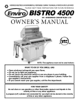
1
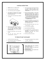
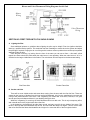
INSTALLATION & OPERATION MANUAL
VENTED MODELS:
NOTE:
26-GBVLP
60-SHBVLP
60-TRBVLP
26-GBVNG
60-SHBVNG
60-TRBVNG
IF YOU HAVE A PROBLEM WITH THIS UNIT DO NOT RETURN IT TO THE
DEALER. CONTACT CUSTOMER SERVICE @ 1-800-245-6489.
Save These Instructions
Questions? Need Parts or Options? www.englanderstoves.com
Please Note the Following Precautionary Statements:
NOTE: THIS UNIT IS NOT A DIRECT VENT STOVE AND THEREFORE REQUIRES 4”
B-VENT GAS PIPE WITH ONE INCH (1”) CLEARANCE TO COMBUSTIBLES. THIS
STOVE IS NOT APPROVED FOR MOBILE HOME OR DOUBLEWIDE
INSTALLATION. DO NOT INSTALL THIS UNIT IN A BEDROOM.
England’s Stove Works highly recommends the use of smoke detectors and Carbon
Monoxide detectors with any hearth product, including this unit. Follow all
manufacturer’s instructions when using smoke or Carbon Monoxide detectors.
WARNING: READ THIS MANUAL PRIOR TO INSTALLATION OF THE UNIT. IF THE
INFORMATION IN THIS MANUAL IS NOT FOLLOWED EXACTLY, A FIRE OR
EXPLOSION MAY RESULT CAUSING PROPERTY DAMAGE, PERSONAL
INJURY OR LOSS OF LIFE. REFER TO AND SAVE THIS MANUAL. CONSULT
A QUALIFIED INSTALLER, SERVICE AGENCY OR YOUR GAS COMPANY
BEFORE INSTALLATION.
WHAT TO DO IF YOU SMELL GAS
•DO NOT TRY TO LIGHT ANY APPLIANCE. OPEN ALL WINDOWS AND EXTINGUISH ANY OPEN
FLAME. DO NOT TOUCH ANY ELECTRICAL SWITCH. DO NOT USE THE TELEPHONE IN YOUR
BUILDING - CALL THE GAS COMPANY FROM A NEIGHBOR’S HOUSE AND FOLLOW THE GAS
COMPANY’S INSTRUCTIONS. IF YOU CANNOT REACH THE GAS COMPANY, CALL THE FIRE
DEPARTMENT.
WARNING: DO NOT STORE OR USE GASOLINE OR ANY OTHER FLAMMABLE
MATERIAL IN THE VICINITY OF THIS OR ANY OTHER HEATING APPLIANCE.
Rev. 5/06
A letter from our Technical Support department:
Thank you for purchasing this fine product from England’s Stove Works!
England's Stove Works was started, and is still owned by, a family that
believes strongly in a "Do It Yourself" spirit – that’s one reason you found
this product at your favorite “Do It Yourself” store.
We intentionally design and build our stoves so that any homeowner can
maintain his or her unit with basic tools, and we're always more than
happy to show you how to do the job as easily and as inexpensively as
possible.
From our free, downloadable service sheets; to our Pellet Service Video;
to our new "wizard-style," click-through Troubleshooting guide on our
web site, we have always tried to help our customers stay "heat-ready,"
especially when oil and electricity prices continue to skyrocket.
Please look at our vast Help section on our web site and call our Customer
Service department at (800) 245-6489 if you need any help with your unit.
We are nearly always able to help “walk you through” any repairs,
problems or questions you may have.
PLEASE NOTE: While information obtained on our web site and through
our 800 number is always free of charge, there will be a service charge
incurred with any “on-site” repairs or maintenance that we may arrange.
Wishing you years of efficient, quality and “comfy” heating,
England’s Stove Works
Technical Support Department
www.englanderstoves.com
(800) 245-6489
IF YOU HAVE A PROBLEM WITH THIS UNIT DO NOT RETURN IT TO THE DEALER.
CONTACT CUSTOMER SERVICE at 1 (800) 245-6489.
SAFETY PRECAUTIONS
THIS VENTED GAS FIREPLACE HEATER MUST BE INSTALLED, REPAIRED AND INSPECTED
ANNUALLY BY QUALIFIED SERVICE PERSONNEL. IT IS ALSO RECOMMENDED THAT IT BE
INSPECTED BEFORE USE. MORE FREQUENT CLEANING MAY BE REQUIRED DUE TO EXCESSIVE
LINT FROM CARPETING AND BEDDING TYPE MATERIAL. IT IS IMPERATIVE THAT THE CONTROL
COMPARTMENTS, BURNERS AND CIRCULATING AIR PASSAGEWAYS BE KEPT CLEAN; FAILURE TO
PROPERLY INSTALL, ADJUST AND MAINTAIN THIS APPLIANCE MAY RESULT IN AN UNSAFE OR
HAZARDOUS CONDITION WHICH MAY LEAD TO CARBON MONOXIDE POISONING, FIRE,
EXPLOSION, PERSONAL INJURY AND LOSS OF LIFE.
DO NOT USE THIS APPLIANCE IF ANY PART HAS BEEN UNDER WATER. IMMEDIATELY CALL A
QUALIFIED SERVICE PERSON TO INSPECT THE APPLIANCE AND TO REPLACE ANY PART OF THE
CONTROL SYSTEM THAT HAS BEEN UNDER WATER.
ALWAYS CHECK YOUR BUILDING CODES PRIOR TO INSTALLATION. THIS INSTALLATION MUST
COMPLY WITH ALL LOCAL, REGIONAL, STATE AND NATIONAL CODES AND REGULATIONS.
THIS UNIT IS DESIGNED TO BURN EITHER NATURAL GAS (NG MODEL) OR LIQUID PROPANE (LP
MODEL) GAS AND IS MADE TO ORDER; THERE IS NO CONVERSION KIT AVAILABLE. NEVER BURN
PAPER, WOOD OR ANY OTHER MATERIAL IN THIS UNIT.
NEVER LEAVE CHILDREN UNATTENDED WHEN THERE IS A FIRE IN THE HEATER.
NEVER USE GASOLINE, KEROSENE, CHARCOAL LIGHTER FLUID OR ANY OTHER LIQUID FUEL
IN THIS UNIT. DO NOT STORE GASOLINE OR OTHER FLAMMABLE MATERIALS IN THE VICINITY OF
THIS HEATER.
THIS VENTED GAS FIREPLACE HEATER MUST BE ELECTRICALLY CONNECTED AND
GROUNDED IN ACCORDANCE WITH LOCAL CODES OR, IN THE ABSENCE OF LOCAL CODES, WITH
THE CURRENT EDITION NFPA 70-NATIONAL ELECTRIC CODE OR CSA C22.1-CANADIAN
ELECTRICAL CODE. WHILE SERVICING THIS UNIT, ALL ELECTRICITY AND GAS SHOULD BE
COMPLETELY SHUT OFF. ALWAYS BE SURE THE STOVE IS COMPLETELY COOLED DOWN PRIOR
TO DOING ANY TYPE OF SERVICE WORK.
THIS STOVE HAS A STANDING PILOT LIGHT THAT IS LIT USING A PIEZO ELECTRIC SPARK
GENERATOR AS DESCRIBED IN OTHER PARTS OF THIS MANUAL. NEVER ATTEMPT TO LIGHT THE
PILOT OR MAIN BURNER WITH A MATCH OR LIGHTER. IF THE PILOT FAILS TO LIGHT AFTER
REPEATED ATTEMPTS, DISCONTINUE OPERATION, TURN OFF THE GAS AT THE VALVE AND
CONTACT A QUALIFIED SERVICE PERSON.
THIS UNIT IS EQUIPPED WITH DECORATIVE CERAMIC FIBER LOGS. IF THEIR DECORATIVE
FIBER BECOMES DAMAGED, THEY MUST BE REPLACED WITH SIMILAR CERAMIC LOGS FROM THE
MANUFACTURER. DO NOT REPLACE THE MANUFACTURER-SUPPLIED LOGS WITH UNAPPROVED
LOGS, REAL WOOD LOGS OR ANY OTHER MATERIAL.
THIS UNIT REQUIRES AN ADEQUATE SUPPLY OF AIR TO PROVIDE VENTILATION AROUND THE
UNIT AND TO SUPPORT COMBUSTION. MOST BUILDINGS HAVE SUFFICIENT AIR INFILTRATION TO
SATISFY THESE REQUIREMENTS; IN SOME INSTANCES, EXTREMELY AIRTIGHT STRUCTURES
MAY REQUIRE THE INTRODUCTION OF OUTSIDE AIR TO ALLOW FOR PROPER OPERATION OF
THE STOVE. REFER TO LOCAL, MUNICIPAL AND NATIONAL INSTALLATION CODES. DO NOT
OBSTRUCT THE FLOW OF VENTILATION OR COMBUSTION AIR, AND DO NOT PLACE CLOTHING OR
FLAMMABLE MATERIAL NEAR THE HEATING UNIT.
ANY SHIELD, DOOR, SAFETY SCREEN OR COMPONENT REMOVED FOR SERVICING THIS
HEATER MUST BE REPLACED PRIOR TO OPERATION OF THE UNIT. IF YOU THINK THE HEATER IS
NOT OPERATING PROPERLY DISCONTINUE THE OPERATION AND CONTACT A QUALIFIED
SERVICE PERSON FOR INSPECTION OF THE UNIT.
England’s Stove Works highly recommends the use of smoke detectors and
Carbon Monoxide detectors with any hearth product, including this unit. Follow all
manufacturer’s instructions when using smoke or Carbon Monoxide detectors.
LISTING AND CODE APPROVALS
THIS VENTED GAS FIREPLACE HEATER HAS BEEN TESTED FOR COMPLIANCE WITH THE ANSI
STANDARD Z21.88-2002 AND THE CANADIAN CSA 2.33-M02 STANDARDS. THIS UNIT IS LISTED
WITH INTERTEK TESTING SERVICES (WARNOCK HERSEY, INC.) OF MIDDLETON, WISCONSIN. ALL
COMPONENTS ARE AGA, CGA, UL OR CSA APPROVED.
THIS APPLIANCE MUST BE INSTALLED IN ACCORDANCE WITH LOCAL CODES, IF ANY; IF NOT,
FOLLOW ANSI Z223.1 (NFPA 54), CURRENT EDITION IN THE U.S. OR CAN1-B149, CURRENT EDITION
INSTALLATION CODE IN CANADA.
NOTE: SEE LABEL ON THE VALVE FOR GAS PRESSURE TESTING LOCATION.
Performance Summary Table
Characteristic
LP Gas
Natural Gas
Fuel requirement
Input rating (0-610m)
Minimum input (0-610m)
Input rating (610 – 1370m)
Orifice size (0-610m)
Max. inlet pressure
Min. inlet pressure
Max. manifold pressure
Min. manifold pressure
Max. efficiency, with fan
Max. output (0-610m)
Gas consumption (std. cond.)
Fuel supply line
Flue exit
Chimney spec.
Ignition
Actual weight
Shipping weight
LP Gas
33,200 BTU/HR
18,600 BTU/HR
30,200 BTU/HR
#51 DMS
13.5” W.C. (3.36 kPa)
11.0” W.C. (2.74 kPa)
10.0” W.C. (2.49 kPa)
3.7” W.C. (0.92 kPa)
81.7%
27,300 BTU/HR
13.3 Cu. Ft/hr or 0.4 gal/hr.
½ inch (13 mm)
4” Diameter (Top or Rear)
Type B-1 (4” Dia.)
Piezo electric & pilot
161 lbs.
185 lbs.
Natural Gas
32,000 BTU/HR
22,500 BTU/HR
29,300 BTU/HR
#33 DMS
10.5” W.C. (2.61 kPa)
4.5” W.C. (1.12 kPa)
3.5” W.C. (0.87 kPa)
0.9” W.C. (0.22 kPa)
77.9%
25,400 BTU/HR
32 Cu. Ft/hr
½ inch (13mm)
4” Diameter (Top or Rear)
Type B-1 (4” Dia.)
Piezo electric & pilot
161 lbs.
185 lbs.
SECTION I: FLUE SYSTEM FOR VENTED GAS FIREPLACE HEATER
A. Installation of a New System (See Installation Drawings at the end of this Manual)
This vented gas fireplace heater must be connected to four-inch (4”) diameter Type B-1 gas
pipe. This product is manufactured and certified to NFPA 54 and NFPA 211 “current edition”
standards. The minimum clearance of this pipe to combustible materials is one inch (1”). Never
use aluminum or galvanized steel pipe with this unit.
Single wall pipe may be used between the stove and ceiling or stove and wall; a minimum of
six inches (6”) clearance to combustible materials is required for this type of pipe. It is imperative
that the single wall pipe be terminated at the ceiling or wall, by connecting to a double wall B-1
Vent Pipe. Single wall pipe should never pass through a combustible wall or ceiling. Follow the
pipe manufacturer’s instructions for venting through a combustible area.
Installation requirements for single wall pipe or Type B-1 Vent Pipe are specified in the ANSI
Z223.1 or CAN1-B149 Standard “current edition.” These standards will also indicate proper
clearances to combustibles. Your stove dealer or qualified service person will be familiar with
these standards and can properly install the chimney system.
Connection of the pipe to the stove is accomplished by placing the pipe over the collar on the
top or rear of the unit; then secure the connection with a screw through the pipe.
Type B-1 Vent Pipe is designed for installation within a building -- it is not intended for outside
use unless it is enclosed in a protective structure and insulated. The requirement for this is clearly
stated in the Venting Tables, Category 1 – Central Furnaces, AGA and GAMA “current edition” for
U.S. Installations and Standards for Gas Vents; National Standards of Canada and CAN/CGAB149.1-M91 for installations in Canada “current edition”. Condensation of exhaust gases may
occur and liquid may run down your chimney if the pipe is not enclosed and insulated. The flue
blockage sensor will also shut the unit down if the stove is not exhausting properly.
B. Existing Flue System
This stove may be connected to an existing pre-fabricated chimney or masonry chimney as
long as the B-1 Vent Pipe passes through the entire length of the chimney. In cases where it is
not possible to use rigid pipe, the four-inch (4”) flex pipe can be substituted. A qualified service
person is best suited for properly retrofitting your existing flue system for use with a gas product.
This vented gas fireplace heater must not be connected to a chimney serving a
separate solid fuel-burning appliance.
SECTION II: UNIT PREPARATION AND PRE-INSTALLATION
A. Unit Preparation
Note: We recommend using a handcart when unloading and placing this stove.
Never attempt to handle this unit without help.
When your unit arrives, it should first be uncrated. Remove all packing material outside the
stove and from the interior of the firebox, and open the firebox by unscrewing the bolt on the right
side of the doorframe. Remove the inflated air bag, instruction manual and wall thermostat from
the interior of the stove. Note: Do not remove the ceramic logs. If you do so by mistake, follow
the guidelines below for proper placement of the logs.
B. Log Placement
The logs are in the proper position when the unit leaves the plant. However, during the
shipping of the unit the assembly can become misarranged. Check to be sure the logs are still
located in the provided slot behind the front portion of the burner tube and the rear of the
assembly is touching the firewall. The front log should be straight up or perpendicular to the floor.
Contact the factory at 1-800-245-6489 if you see a cracked or broken log.
C. Top or Rear Vent
Your stove comes with the option of venting out of the top or rear of the unit. The stove must
be set up for the desired venting direction prior to operating the unit.
First, remove the two screws that hold the grilled top onto the stove. They are located on the
back of the stove near the top.
For the top exit installation, place the flue collar on the top of the stove and fasten it with the
four (4) bolts, nuts and washers. Install the flue cover plate on the rear opening of the unit using
the supplied bolts, nuts and washers.
Next, find the vent safety shut-off switch inside the draft hood on the back of the stove. It is the
small disc-shaped object screwed to an L-shaped bracket; there are two (2) sets of holes on this
bracket. Position this vent safety shut-off switch as far up in the flue as possible, or in a direction
heading toward the ceiling. This is accomplished when the lower set of holes in the bracket is
aligned with the two holes in the back of the stove.
For the rear exit method, place the flue collar on the rear of the stove and fasten it with the
four (4) bolts, nuts and washers. Install the flue cover plate on the top of the unit with the supplied
bolts, nuts and washers.
Next, find the vent safety shut-off switch inside the draft hood on the back of the stove. It is the
small disc-shaped object screwed to an L-shaped bracket; there are two (2) sets of holes on this
bracket. Position the vent safety shut-off switch so the switch is as far down in the flue as
possible, or in a position closest to the floor. This is accomplished when the upper set of holes on
the bracket is aligned with the two holes in the back of the stove.
D. Gas Pressure
The input rate of this vented gas fireplace heater is 33,200 BTU/HR with liquid propane
and 32,000 BTU/HR with natural gas. The supply gas pressures are listed in the manual under
the LISTING AND CODE APPROVALS and outlined under the “Performance Summary Table”
listed earlier. The gas supply line should be ½” in diameter with ½” male NPT for connection to
the stove. This connection point is found on the lower rear portion of the heater. It is also helpful
to install a 1/8” NPT plugged tap at the inlet to the stove for checking the inlet gas pressure. In
addition, it would be useful to add a manual gas shutoff at the inlet to the stove.
The inlet gas pressure to the stove should be adjusted in accordance with the guidelines
stated in the “Performance Summary Table.” The vented gas fireplace heater and its individual
shutoff valve must be disconnected from the gas supply piping system during any pressure
testing of that system at test pressures in excess of ½ PSIG (3.5 kPa).
E. High Altitude Installation
For Canadian installations, this stove is certified for elevations from 0 – 2000 feet
(0-610m) above sea level. For Canadian installations above 610 – 1370 meters, the orifice size
for natural gas is #35 DMS, and for liquid propane the size is #52 DMS per CAN/CGA 2.17 tests,
“current edition.”
For high altitude installations, consult the local gas distributor or the authority having
jurisdiction for proper rating methods. If the installer must convert the unit to adjust for varying
altitudes, the information sticker must be filled out and adhered to the appliance at the time of
conversion. (Sample Sticker:)
→This appliance has been converted for use at an altitude of _____________________
Orifice size ___________________
Manifold Pressure ___________________
Input (Btu/HR) __________________
Fuel Type
___________________
Conversion Date ________________
Converted by
___________________
At the higher altitudes, gas codes make it necessary to decrease the amount of gas
input. This decrease in gas flow is accomplished by using an orifice of the correct size. The input
should be reduced by four percent (4%) for each 1000 feet above sea level — a qualified gas
service person can determine the correct burner orifice. The unit is shipped with a #51 DMS
orifice for LP and a #33 orifice for natural gas.
All installation aspects of this stove must conform to the national fuel gas “listing and
code” ANSI Z223.1/NFPA 54 or CAN1-B149 “current edition.”
SECTION III: WALL AND FLOOR PROTECTION
A. Heater Location and Wall Protection
This freestanding stove is a high efficiency unit, which means it gives off a great deal of heat.
For this reason, the unit should not be located in a traffic area or near drapes or curtains, which
present a fire hazard. It is important to allow for adequate clearance between the stove and the
nearest combustible; the unit must be at least three inches (3”) from a rear wall and twelve inches
(12”) from a combustible sidewall.
B. Floor Protection
This stove may be installed on a hard
combustible surface such as a wood floor,
and it may also be installed on noncombustible surfaces such as brick, marble
or slate. Floor protection will be required if
this unit is placed on a combustible material
other than wood.
SECTION IV: FREESTANDING
HOOK-UP
A. Chimney Connector
The chimney connector must be four inch
(4”) diameter single wall pipe or Type B-1
Vent Pipe. If a single wall pipe is selected as
a chimney connector, it should only be used
between the stove and the ceiling or the
stove and the wall. A single wall pipe must be
terminated at the ceiling or wall and changed
to type B-1 pipe and used with the proper
wall or ceiling pass-through kits.
Do not use aluminum or galvanized steel
pipe, as neither is designed for use with your
gas heater. Never use single wall pipe as a
chimney; you must connect your stove to a
chimney comparable to those listed earlier in
this manual.
The flue connector pipe must be installed
on the stove so it goes outside the flue collar. In
Appropriate Clearances for
other words, after the chimney connector pipe is
Vented
Gas Unit Installation
installed, the pipe will completely cover the flue
collar. The pipe will be marked with arrows, and
all pipe should be installed with these pointing up or away from the unit. These are called
“direction of flow markings” and should be oriented properly. (See Installation Drawings at the
end of this Manual.)
B. Thermostat
Your stove comes supplied with a wall thermostat that controls the temperature of the unit and
room. This thermostat is compatible with the low voltage electrical system (0.75 volt or 750
millivolts) of your stove. If you decide not to use the thermostat supplied with the stove, be sure to
use one that is compatible with the operation of a “millivolt” system.
When planning your stove location, be sure to consider the thermostat. The thermostat
should not be located more than twenty feet (20’) from the stove and should be at a height of at
least five feet (5’) above the floor. It is recommended that insulated 18-gauge wire be used to
achieve optimal performance (ten feet of wire is furnished with the thermostat). If the thermostat
has to be placed farther away from the stove, it is recommended that a larger gauge wire be
used. It is a good idea to leave some extra wire behind the stove so the unit can be moved out for
cleaning.
Mount the thermostat level for proper operation, and follow the manufacturer’s directions
for installing this part.
SECTION V: BLOWER
The blower is standard on your vented gas fireplace heater and provides 100 CFM of circulating
air capability – it operates on 115 volts AC, 60 HZ power source and draws 1.5 AMPS. The
blower is attached to the rear of the stove with four (4) screws.
Blower activation is achieved with a temperature switch that mounts to the back of the firebox.
When the back wall of the stove heats up, the blower will activate and when it cools down, the
blower will automatically shut off. The blower will activate at the speed as set on the variable
speed dial.
SECTION VI: OPERATING INSTRUCTIONS
WARNING
Children and adults should be alerted to the hazards of high surface temperatures of the
appliance and should stay away to avoid burns or ignition of clothing. Young children
should be carefully supervised when they are in the same room as the appliance.
CAUTION
•If the door is removed for service it must be replaced prior to operating this appliance.
•Clothing or other flammable material should not be placed on or near the appliance.
•Before operating this heater, please review the safety precautions given earlier in the manual.
•Check the logs for proper location.
•Check for gas leaks – soap and water can be used to expose suspected leaks.
•Verify that the connector pipe and chimney is unobstructed.
•Be sure the door is properly sealed.
•When installing the blower, check all connections to avoid electrical shock.
•Open the gas valve access door to get to the valve; this will also expose the instructions.
FOR YOUR SAFETY READ BEFORE LIGHTING
WARNING: If you do not follow these instructions exactly, a fire or explosion may
result causing property damage, personal injury or loss of life.
1. This appliance is equipped with a manual piezoelectric ignition device. Do not try to light the
pilot by hand.
2. Before lighting, smell around the appliance area for gas. Be sure to smell next to the floor
because some gas is heavier than air and will settle on the floor.
3. Use only your hand to turn the gas valve control knob. Never use tools. If the knob will not
turn by hand, do not try to repair it, but call a qualified service technician. Force or attempt to
repair may result in fire or explosion.
4. Do not use this appliance if any part has been under water. Immediately call a qualified
service technician to inspect the appliance and to replace any part of the control system and
any gas valve control that has been under water.
WHAT TO DO IF YOU SMELL GAS:
•
•
•
•
•
Do not try to light any appliance.
Do not touch any electric switch; do not use any phone in your building.
Immediately call your gas supplier from a neighbor’s telephone.
Follow the gas supplier’s instructions.
If you cannot reach your gas supplier, call the fire department.
LIGHTING INSTRUCTIONS
1.
STOP! Read “For Your Safety” above.
2.
Set the thermostat to lowest setting.
3.
Turn off all electric power to the appliance.
4.
This appliance is equipped with a manual
piezoelectric ignition device. Do not attempt
to light the pilot by hand.
5.
Turn gas valve control knob fully clockwise
→ to “OFF.”
9.
Push in the gas valve control knob and hold
it in while pushing the button of the
piezoignitor. Push the piezoignitor button
several times while holding the gas valve
control knob in.
10. After the pilot has ignited, you may cease
pushing the piezoignitor button. Continue to
hold the gas valve control knob for
approximately 30-60 seconds. Release the
gas valve control knob and it will “pop” out.
If the knob does not pop up when
released, stop and immediately call your
service technician or gas supplier.
The pilot is now lit.
11. For the very first lighting, it may take several
attempts to purge air from the gas line. If
pilot ignition does not occur or the pilot goes
out, repeat steps 9 and 10.
12. Turn the gas valve control knob fully
counterclockwise ← to “ON.”
6.
Wait five (5) minutes to clear out any gas. If
you then smell gas, STOP! Follow the
“For Your Safety Read Before Lighting”
information earlier. If you do not smell gas,
go to the next step.
7.
Be sure the thermostat is set at the lowest
setting.
8.
Turn the gas valve control
counterclockwise ← to “PILOT.”
knob
13. Turn on all power to appliance.
14. Set thermostat to desired setting.
15. If the appliance will not operate, follow the
instructions “TO TURN OFF GAS TO
APPLIANCE” and call your service
technician or gas supplier.
16. Shut the gas valve access door.
TO TURN OFF GAS TO APPLIANCE
1.
Set the thermostat to lowest setting.
3.
Turn gas valve control knob fully clockwise
→ to “OFF.” Do not force.
2.
Turn off all electric power to the appliance if
service is to be performed.
4.
Shut gas valve access door.
1. White Rogers Pilot Light Assembly
(located in the firebox)
2. Spill Switch (located in the draft hood
beneath the flue collar)
3. Wall Thermostat
4. Piezoelectric Spark Ignitor (located near
the gas control valve)
Blower and Valve/Thermostat Wiring Diagrams for this Unit
Blower
Wiring
Valve/Thermostat
Wiring
SECTION VII: FIRST FIRE HINTS YOU SHOULD KNOW
A. Lighting the Pilot
Some additional pointers or guidelines about lighting the pilot may be helpful. First time ignition should be
done by a qualified service person. This technician has the knowledge to trouble shoot the system and adjust
the pilot light if required. Purging the air out of the gas line is also a common problem that could require repeated
attempts to light the pilot.
Once the pilot is burning, by looking from the front of the stove you can see a flame -- this small, yellow
tipped, blue flame should be visible when the main burner is not operating. When the main burner is on, it is
evident from the larger visible flame in the firebox. The main burner will now respond to the thermostat setting.
Pilot Flame Size
Firebox Flame Size
B. Smoke and Odor
There will be some visible smoke and some odors coming from the stove with the first few fires. These are
caused by the burning of binders from the logs and brick fiberboard, oils from the manufacturing process and
curing of the painted surface of the stove. This “off-gassing” will cease after a few fires; however, it is a good
idea to open some windows and doors in your dwelling during this time.
While this “off-gassing” is occurring, the brick fiberboard will turn a dark color. This is only a temporary effect,
and it should return to the original color after a few fires.
In the beginning, the flames will be taller than normal, and may even hit the top inside of the stove. The
binder in the logs and brick fiberboard acts as fuel, and can make the flame burn higher. This will correct itself
after a few fires and the flame should stabilize at a height of no more than 85% of the front glass window.
C. Glass Windows
This unit is manufactured with high temperature ceramic glass, and substitute materials should not be used.
This stove should not be operated if the glass is cracked, broken or removed.
The glass/frame assembly shall be replaced as a complete unit as supplied by the manufacturer. The
replacement of the glass should done by a licensed or qualified service person. This stove has a middle and two
side glasses that mount inside the door frame. The glass can be changed by removing the window bracket that
is located in the bottom inside of the door frame. The bracket can be removed by raising it up and removing it
through the small channel located on the lower left side of the door frame. The new glass with gasket can then
be placed in the proper space and the channel snapped back into place. The replacement glass is designed for
our units only and can be ordered by calling (Parts Orders Only: 1-800-516-3636).
When the stove is first started, the glass will fog up with condensation from the combustion process. The
condensation will evaporate and disappear as the glass and stove reach full operating temperature, which will
usually take two to three minutes.
If you happen to see a grey film or haze forming on the inside of the glass, it should be removed
immediately; this could be from the logs not being located properly and too much flame hitting them. The haze
can be removed in the early stages, but is permanent if left on too long. The logs should be all the way to the
back and left inside the stove.
WARNING: DO NOT USE ABRASIVE CLEANERS. ALLOW THE UNIT TO COOL DOWN BEFORE
CLEANING THE GLASS. DO NOT ABUSE THE GLASS BY SLAMMING THE DOOR OR
STRIKING THE GLASS.
D. Valve and Burner Controls
1) Variable Heat Input Controls
On the gas valve, to the left of the green or black gas control valve knob is another control. This is the
variable heat input control that continually varies the gas going into the stove from low to high. The high setting
allows the maximum amount of gas to enter your stove, and is used for cold winter nights or when you desire to
heat a larger space; the low setting may be used during the spring and fall months when not as much heat is
required. The low setting gives approximately 50% of the heat as compared to the high setting.
2) Air Shutter Adjustment on the Burner Tube
The air shutter is an adjustment on the burner tube. Its purpose is to control the amount of air that enters the
burner tube. In concept, opening the shutter permits more air to enter the tube and causes the flames on the
main burner to be bluer and burn cleaner. Closing the shutter has the opposite effect, and causes the flame to
burn orange and dirtier. Note: Only a qualified service technician should make Air Shutter adjustments.
E. Seasonal Shut-down
At the end of the season, the stove should be shutdown completely, which will conserve gas and save you
money.
First, move the thermostat control or lever to the “OFF” position.
Then, shut off the gas to the main burner by turning the gas valve control knob fully clockwise → to the “OFF”
position.
F. Lighting the Heater During Regular Use
Simply turn up the switch on the wall thermostat to the desired temperature. If the thermostat temperature is
greater than the room temperature, the heater will come on immediately. If the thermostat temperature is less
than the room temperature, the main burner will not come on until the temperature falls below the thermostat
setting.
G. Shut-down During Regular Use
Move the thermostat switch to the “OFF” position. Please note while the thermostat is in this position the pilot
light still remains on, but the unit will not light.
SECTION VIII: MAINTENANCE
A On a routine basis check around, beside, behind and under your vented gas fireplace heater to be sure that
no combustible material has been placed close to it. Items like paper bags, newspapers, dust, clothing, liquids
with flammable vapors, flammable liquids and all other combustibles should be kept away from the heater.
B. Keep the main burner, burner ports, pilot and valve clean of metal flakes from minor corrosion (carbon or any
other foreign material) that may occur from the high temperatures. Turn the thermostat and gas valve to the
“OFF” position before any cleaning procedure.
Note: Let the unit cool down to room temperature before cleaning! It is recommended that you use a
clean, dry paintbrush to clean the interior of the stove and a vacuum cleaner to remove the carbon from the logs.
The glass in the door may be cleaned with a glass cleaner, but we advise never to use an abrasive cleaner for
this operation.
C. Check the venting system at the beginning and the end of each heating season to be sure it is connected
properly and no blockages have occurred. A qualified technician should do this.
REPLACEMENT PARTS
DESCRIPTION
Front Glass
Side Glass
4” Blank Flange
4” Flue Collar
Front Door
Flue Blockage Switch
Thermopile
Pilot Orifice
Burner Orifice
Gas Valve
Pilot
Burner
Large Window Brass Trim
Small Window Brass Trim (2)
Front Log
Middle Log
Back Log
Left Log
Right Log
Thermostat
Remote Thermostat
PART NUMBER
AC-G14
AC-G13
CA-3029
CA-3031
GU-GBVD
GU-60T11
GU-214212
GU-F69-2064(LP only) GU-F69-20631(NG only)
GU-LP051 (LP only) GU-NG033 (NG only)
GU-3LCLP (LP only) GU-4LCNG (NG only)
GU-EDI-701
GU-3025
AC-106-G
AC-106-GB
GU-4801
GU-4802
GU-4803
GU-4804
GU-4805
GU-1E30-914
AC-3001
Note: All replacement parts can be ordered from your local dealer or from the factory at
(Parts Orders Only) 1-800-516-3636.
If you have any questions or problems contact the Customer Service Department.
[email protected]
CUSTOMER SERVICE DEPARTMENT
P.O. BOX 206
Parts Orders Only: (800-516-3636)
MONROE, VA 24574
Questions/Help: (800-245-6489) (FAX: 434-929-4810)
Trouble Shooting Guide
Warning: To avoid electrical shock, always disconnect the unit before attempting any
trouble shooting procedures (unless otherwise indicated in this manual). If the solution
in this guide does not correct the problem, consult your local dealer or call the factory.
“Caution: Label all wires prior to disconnection when servicing controls. Wiring errors
can cause improper and dangerous operation” and “Verify proper operation after
servicing.”
Problem
Cause
Solution
1. Pilot doesn’t light.
Gas not on.
Piezo ignitor not sparking.
Misaligned Piezo ignitor.
Air in the lines.
Turn gas on.
Check for spark w/door closed.
Adjust spark to be 1/8” to hood.
Bleed air from line.
2. Pilot doesn’t stay lit.
The thermopile’s not fully
surrounded by the flame.
Wiring is loose in system.
Defective thermopile.
Adjust the thermopile so the
flame directly impinges upon it.
Tighten any loose wires.
Replace thermopile.
3. No ignition to burner.
Gas is off.
Pilot is off.
Thermostat is set too low.
Thermostat is defective.
Turn on gas.
Light by instructions.
Move to higher setting.
Connect the 2 thermostat
wires together. If the unit lights,
the thermostat is bad – replace it.
4. Carbon deposits on
Logs not in properly.
Incorrect burner orifice.
Air shutter out of adjustment.
High altitude, check orifice.
See “Log Placement” in manual.
Compare size as in table.
Open air shutter slightly.
Match orifice to altitude.
5. Glass fogs up.
Normal for 2 to 3 minutes.
No action required.
6. Blue flames.
Normal for first 20 minutes.
No action required.
7. Repeated on, off cycle.
Heat shutting off thermostat.
Flue blockage sensor.
Move farther from unit.
Check flue for blockage or
downdraft.
8. Unsatisfactory burn.
Gas pressure incorrect.
Contact local gas supplier.
logs, glass or burner.
Installation Drawings – Through-the-Ceiling and Through-the-Wall
Note: When running double-walled pipe up the side of home, you must build
a chase around the chimney pipe.
Have this information on hand if you telephone the factory or your dealer regarding this product.
(Retain for your files)
Model Number __________________________________
Date of Purchase ________________________________
Date of Manufacture ____________________
Serial #__________________________
LIMITED 5 YEAR WARRANTY FROM THE
DATE OF PURCHASE TO THE ORIGINAL OWNER
The manufacturer extends the following warranties:
1. Carbon steel and welded seams in the firebox are covered for 5 years against extreme warpage and welded
seams from splitting.
2. The burner, valve, tubes and glass are warranted for 1 year.
3. Electrical components such as the blower and thermostat are warranted for 1 year. This warranty does not
apply if damage occurs because of an accident, improper handling, improper operation, improper
installation, shipping damage, abuse, or unauthorized repair made or attempted to be made. Purchaser
must give notice of claim of defect within the warranty period and pay any transportation expense to and
from a service center designated by the factory for service. The dealer from whom the stove was purchased
or the factory will perform warranty service at our option.
4. All liability for any consequential damages for breach of any written or implied warranty is disclaimed and
excluded there from. Some states do not allow the exclusion or limitations of consequential damages, so the
above may not apply to you. This warranty gives you specific legal rights, and you may also have other
rights that vary from state to state.
THIS WARRANTY IS NULL AND VOID IF YOU DO NOT RETURN THE ATTACHED WARRANTY SHEET
WITHIN 30 DAYS FROM THE DATE OF PURCHASE.
WARRANTY IS NOT TRANSFERABLE
WARRANTY REGISTRATION for England’s Stove Works
Purchased by (Name) ______________________________________________
Address _________________________________________________________
City ________________________ State __________ Zip _________________
Telephone _______________________________________________________
Email Address ____________________________________________________
DEALER INFORMATION
Purchased From (Dealer) ___________________________________________
Address _________________________________________________________
City ________________________ State __________ Zip _________________
UNIT INFORMATION
(Please be sure to refer to sticker on back of manual or box to complete this section)
Model Number _____________________ Purchase Date _________________
Purchase Price ____________________
Serial Number _____________________ Mfg. Date ______________________
How did you first hear about our product? (please check one)
___ Word of Mouth
___ Burn Trailer Demonstration
___ Internet
Other: ____________________________________________________
Where did you receive information about our product? (please check one)
___ Rec’d. info. via phone ___ Dealer (Name of dealer): ______________________
___ Internet
Other: _________________________________________________
IMPORTANT NOTICE
THIS REGISTRATION INFORMATION MUST BE ON FILE FOR THIS WARRANTY TO BE VALID.
PLEASE MAIL THIS INFORMATION WITHIN THIRTY (30) DAYS FROM THE DATE OF
PURCHASE.
Mail To:
England’s Stove Works, Inc.
Customer Service Department
P.O. Box 206
Monroe, VA 24574
Or, Fax To:
(434) 929-4810 – 24 hours a day
Or, now available – Go online to complete your Warranty Registration!
Visit www.englanderstoves.com if you prefer to register online.