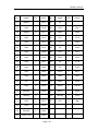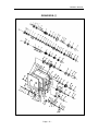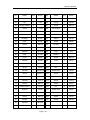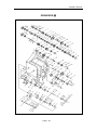
1
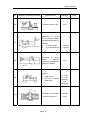
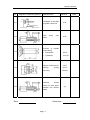
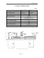
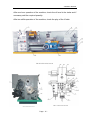
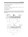
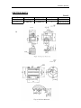
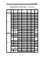
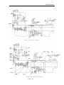
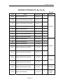
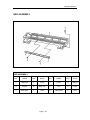
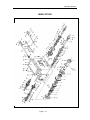
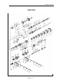
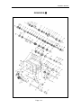
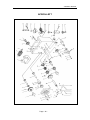
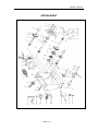
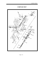
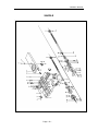
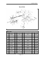
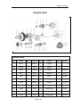
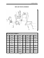
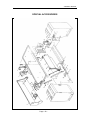
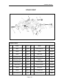
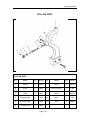
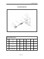
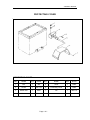
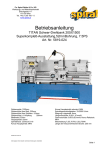
Code 505116
CQ6230A-2/910
Metal Turning Lathe
OWNER’S MANUAL
CONTENTS
1.
NOTE----------------------------------------------------------------------------------
2
2.
LIMITED WARRANTY------------------------------------------------------------
2
3.
PASSPORT DATA-----------------------------------------------------------------
3
4.
TEST PROTOCOL----------------------------------------------------------------
4
5.
GENERAL DESCRITION OF THE MACHINE------------------------------ 7
GENERAL DATA-------------------------------------------------------------------- 7
BASIC TECHNICAL DATA-------------------------------------------------------- 9
6.
DESCRIPTION FO THE MAIN UNITS---------------------------------------- 10
GEAR BOX--------------------------------------------------------------------------- 10
QUADRANT-------------------------------------------------------------------------- 10
FEED BOX--------------------------------------------------------------------------- 10
CARRIAGE GROUP--------------------------------------------------------------- 10
THREAD INDICATOR------------------------------------------------------------- 11
TAIL STOCK-------------------------------------------------------------------------- 11
RESTS--------------------------------------------------------------------------------- 11
7.
MACHINE INSTALLATION------------------------------------------------------ 12
TRANSPORTATION--------------------------------------------------------------- 12
UNPACKING------------------------------------------------------------------------- 12
HANDLING--------------------------------------------------------------------------- 12
PREPARATION---------------------------------------------------------------------- 12
MOUNTING, FOUNDATIONS AND LEVELLING--------------------------- 12
CONNECTION TO THE EL. SUPPLY SOURCE--------------------------
13
PUTTING INTO OPERATION--------------------------------------------------- 13
8.
MACHINE SERVICE-------------------------------------------------------------- 15
LUBRICATION---------------------------------------------------------------------- 15
RECOMMENDED LUBRICANTS---------------------------------------------- 16
9.
MACHINE OPERATION---------------------------------------------------------- 17
PUTTING INTO OPERATION--------------------------------------------------- 17
CUTTING OF THREAD AND FEEDS----------------------------------------- 17
FRETTED PARTS------------------------------------------------------------------ 20
10. MECHANISM’S ADJUSTMENT------------------------------------------------ 21
11. SAFETY------------------------------------------------------------------------------- 21
12. MACHINE CARE AND MAINTENANCE------------------------------------- 22
13. TRANSMISSION SYSTEM & PARTS---------------------------------------- 23
14. BEARING DISTRIBUTION------------------------------------------------------- 26
Page - 1 -
OWNER’S MANUAL
NOTE
This manual has been prepared for the owner and operators of this lathe.
Its purpose, aside from machine operation, is to promote safety through the
use of accepted correct operating and maintenance procedures.
Completely read the safety and maintenance instructions before operating
or servicing the machine. To obtain maximum life and efficiency from your
lathe, and to aid in using the machine safety, read this manual.
Since we continually strive to incorporate latest developments in the
construction of the lathe, it is quite possible at time, due to printing and
shipping requirements, some data may not correspond to the lathe in the
question.
LIMITED WARRANTY
We makes every effort to assure that our products meet high quality and
durability standards and warrants to the original retail consumer/purchaser of
our products that each product be free from defects in materials and
workmanship as follow: 1YEAR LIMITED WARRANTY ON ALLPRODUCTS
UNLESS SPECIFIED OTHERWISE. This Warranty dose not apply to defects
due directly or indirectly to misuse, abuse, negligence or accidents, normal
wear and tear or alterations outside our facilities, or to a lack of maintenance.
We shall in no event be liable for death, injuries to persons or for incidental,
contingent, special, or consequential damages arising from the use of our
products.
To take advantage of this warranty, the product or part must be returned to for
examination, postage prepaid. Proof of purchase date and an explanation of
the complaint must accompany the merchandise. If our inspection discloses a
defect, we will either or replace the product, or refund the purchases price if we
cannot readily and quickly provide a repair or replacement, if you are willing to
accept a refund. We will return repaired product or replacement at our expense,
but if it is determined there in no defect, or that the defect resulted from causes
not within the scope of our warranty, then the user must bear the cost of storing
Page - 2 -
OWNER’S MANUAL
and returning the product.
Page - 3 -
OWNER’S MANUAL
PASSPORT DATA
Model:
Serial No.:
Main el. motor:
V
Ph
Hz
GEOMETRIC ACCURACY CHECKING
The machine lathe guide way horizontality shall be checked in longitudinal and
transverse direction towards the machine axis by the help of level with an
accuracy up to ±0.02/1000 mm and ± 0.04/1000 mm. before starting any
accuracy measurement.
To avoid one-sided loading of the machine body, place the carriage in the
center of the body while leveling.
Page - 4 -
OWNER’S MANUAL
TEST PROTOCOL
No.
Diagram of measuring method
Inspection item
Tolerance
a.
Alignment
of
longitudinal bed slide
ways in vertical place
Full travel
0.25 (+)
b.
Parallelism
of
transverse direction
1000:0.06
G1
G2
Parallelism
of
tailstock
to
longitudinal motion of
carriage.
a.
In vertical plane
b.
In
horizontal
plane
G3
Spindle nose run out
G4
Spindle taper run out
a. At the end of
spindle nose
b. At the end of
300mm test bar
G5
Parallelism of spindle
center
line
to
longitudinal motion of
carriage
a.
In vertical plane
(upward)
b.
In
horizontal
plane (forward)
Page - 5 -
a. 500:0.03
b. 500:0.025
0.015
a. 0.01
b. 300:0.03
a. 300:0.02
b. 300:0.02
Data
OWNER’S MANUAL
No.
Diagram of measuring method
Inspection item
Tolerance
G6
Spindle center run out
0.02
G7
Parallelism of center
line of tailstock spindle
to longitudinal motion of
carriage
a.
In vertical plane
b.
In horizontal plane
G8
Difference in center
height
between
headstock and tailstock
(tailstock upward)
G9
Spindle
a. Axial run out
b. Run out on spindle
base plane
G10
Verticality of cross slide
to spindle center line
Page - 6 -
a.
200:0.03
b. 200:0.03
0.06
a. 0.015
b. 0.02
(axial run
out
included)
0.02/150
a ≥90°
Data
OWNER’S MANUAL
No.
Diagram of measuring method
Inspection item
Tolerance
G11
Parallelism of top slide
to spindle center line
0.04
G12
Lead
action
0.03
G13
Accuracy of outside
round cutting
a. Roundness
b. Cylindricity
screw
cam
a. 0.015
b.
300:0.04
G14
Flatness of the face for
finishing
cutting
(concave)
0.015
(for Ø
160mm)
G15
Precisely
thread
cutting on work piece
between tow centers
(steel)
7g
Date:
Supervisor:
Page - 7 -
Data
OWNER’S MANUAL
1. GENERAL DESCRIPTION OF THE MACHINE
1.1. GENERAL DATA
MAIN ASSEMBLIES (See Fig. 1a)
1.
2.
3.
4.
5.
6.
7.
8.
9.
10.
11.
12.
Bed way
Headstock
Feed box
Carriage box
Electrical box
Chuck protecting cover
Splash guard
Lower carriage
Top carriage
Cooling
Working light
Tailstock
13.
14.
15.
16.
17.
18.
19.
20.
21.
22.
Leads crew (with Guard)
Feed rod
Switch rod
Tool holder
Quadrant
Oil tray
Steady rest
Foot stand
Thread indicator
Foot brake
23. 3 jaw chuck
CONTROLS (See Fig. 1b)
1. Lever for starting, stopping and reversing the carriage feed movement
while threading
2. Lever for spindle speed stages
3. Wrench for the tool-holder
4. Flywheel for shifting the tool-holder slide
5. Handle for tail-spindle fixing
6. Handle for tailstock fixing
7. Flywheel for tail-spindle shifting
8. Handle for starting or stopping of the carriage longitudinal shifting while
threading
9. Lever for starting the spindle in forward or reverse stroke and its stopping.
When shift in forward direction, the spindle will turn counter-clockwise, and
when shift in backward direction, the spindle will turn clockwise. When in
the center position, the spindle stopped.
10. Lever starting and stopping the carriage transverse and longitudinal
shifting.
11. Flywheel for manual shifting of the carriage in longitudinal direction
12. Flywheel for feeding the cross slide
13. Drum (handle) for selection of “feed” or “thread”
14. Button-emergency stop
15. Switch-coolant pump
16. Button-test bottom for the main el. motor
17. Signal lamp. It glows when the main el. motor is switched on
Page - 8 -
OWNER’S MANUAL
Page - 9 -
OWNER’S MANUAL
1.2. BASIC TECHNICAL DATA
Form 1
Max swing over bed
Max swing over gap
Max swing over cross slide
Distance between centers
Taper of spindle bore
Range of spindle speed
Taper of spindle bore
Taper of tailstock spindle
Max. travel of carriage
Max. travel of cross slide
Max. travel of top slide
Max. travel of tailstock spindle
Motor power
CQ6230 SERIAL
C0632C
Ø 300 mm
Ø 320mm
Ø 430 mm
Ø 450mm
Ø 180 mm
Ø 180mm
900 mm / 750 mm 1000 mm
38 mm
9 steps 75—1400 rpm /
18 steps 65-1810 rpm
M.T. 5
M.T. 3
760mm / 560 mm
880 mm
130 mm
75 mm
100 mm
1.1 KW / 1.5 KW
Page - 10 -
OWNER’S MANUAL
2. DESCRIPTION OF THE MAIN UNITS
GEAR BOX
The gear box is mounted on the machine corp. the rotation motion to this gear
box is transferred through V-belts and belt pulley from an el. motor mounted on
the guide way.
QUADRANT
The quadrant is destinated to transfer the motion from the gear box to the feed
box through some change gears. It is mounted in the quadrant box. The latter
is closed by a cover.
FEED BOX
The feed box is fixed to the face side of the machine corp.—just below the gear
box. It includes all the mechanisms, by the help of which is effected the
adjustment for selection of the feed or thread pitches.
Required adjustments for the different values of the feed or thread pitch are
realized by the help of respective drums, located on the front part of the feed
box.
CARRIAGE GROUP AND ITS MECHANISMS
The carriage group is destinated for fixing and driving the cutting too. It
includes five basic parts: carriage box, carriage board, lower slide, cross piece
and upper (top) slide.
A. Carriage box
The carriage box is mounted on the carriage board. It contain the mechanisms
that are used for driving the carriage longitudinal and cross feed, as well as the
mechanism for engagement of the nut to the lead-screw while threading and
the mechanism for manual feed of the carriage.
B. Carriage board
The carriage board is mounted on the corp. guide ways. All the rest parts of the
carriage group are fixed to this carriage board.
C. The lower slide moved on the guide ways of the carriage board in
Page - 11 -
OWNER’S MANUAL
transverse direction. This movement may be effected automatically or
manually.
D. When short cones have to turned by hand, the cross piece may be
swiveled at 90° towards the lower slide in both directions and be fixed in the
required position by the help of suitable bolts and nuts.
E. The top slide on which the four-position tool holder is mounted, may be
shifted only by hand in the direction of the cross-piece.
Thus you may obtain longitudinal, cross and combined feed for the cutting tool.
THREAD-INDICATOR
This device is mounted to the carriage box (disengaged to the driving screw)
for getting into thread pitch
TAIL STOCK
The tailstock is clamped to the corp. guide ways. It is designed for working
piece clamping during machining between centers for drilling operations with
manual feed of the tool.
RESTS
In response to the special request of the client, the lathe may be competed
additionally with a steady and a follow rest.
The two types are with sliding quills. The steady rest is fixed to the corp. guide
ways and the follow rest to the carriage board.
Page - 12 -
OWNER’S MANUAL
3. MACHINE INSTALLATION
TRANSPORTATION
The machine is transported in a special wooden case (or with foot stands
separately packed in carton), being fixed to the base of the case or slide by
suitable bolts. Some of the accessories are mounted on the lathe well fixed
and the other packed in a separate box or directly fixed on the case base.
The places where the ropes or chains have to be passed during handling of the
packed machine are marked on the packing. Be aware of the heavy side while
you are handling the machine with forklift.
UNPACKING
After the machine had been unpacked, check carefully its general condition, as
well as the availability and condition of all the accessories, shown in the
packing list.
HANDLING
Unpacked machine shall be handled only by the help of a suitable crane.
Before passing the ropes over the specified places, shown on the Fig.2, pull
out the tailstock and carriage and fix them in the rear hand position so that
when lifting the machine you will obtain required balancing. When handling the
machine never strike or hit it sharply because this may affect the machine
accuracy—irrespective of whether there are or not may visible defects.
Since the paint on some part of the machine may be damaged during handling,
place protective pads of fabrics or other suitable material on the respective
places.
PREPARATION
Before mounting the machine on the predetermined place, clean it carefully
from the protective oil. Respective machine surface shall be washed by the
help of pure naphtha or benzine.
This protective oil shall not be removed by hard objects or solvent that may
damage the metal surface or paint of the machine. Well-cleaned surfaces are
dried by the help of dry threads and covered with pure machine oil. Remove
the end gear cover. Clean all components of the end gear assembly and coat
all gears with heavy, non-slinging grease.
MOUNTING, FOUNDATIONS AND LEVELLING
To obtain accurate, durable and trouble-free operation of the machine, mount it
only on suitable, foundation and level it carefully. The foundation is prepared
Page - 13 -
OWNER’S MANUAL
by concrete with a thickness from 200 to 300 mm according to the soil
strengthness.
The unpacked machine is lifted by crane according to the specified method
and after the anchor and leveling bolts are in place, lower the foundation so
that the anchor bolts enter into the respective holes. The leveling plates (shims)
are placed below the leveling bolts. The guide way horizontality is checked in
longitudinal and transverse direction towards the machine axis by the help of
level with an accuracy of ±0.02/1000 mm and ± 0.04/1000 mm. After this initial
machine leveling had been carried out, pour the holes for the anchor bolts and
the space blew the machine legs with cement putty with ratio between the
cement and sand 1:3
After the cement is setted well (3-4days), tighten the nuts of the anchor bolts
carefully and evenly.
Check the machine leveling once again and if necessary—correct it by the help
of the leveling bolts.
CONNECTION TO THE EL. SUPPLY SOURCE
Check whether the data on the el. panel scheme (voltage and frequency of the
supply source) correspond to the available.
The controlling level should remain in the middle and also press down the
switch to keep the machine power off.
Make sure the lathe in properly grounded.
PUTTING INTO OPERATION
Before starting the machine, clean it once again carefully and lubricate it
according to the Fig. 3a 3b 3c –Lubrication System.
Check the V-Type belt, which located from motor to the low speed wheels,
whether it’s too tight or not. Too tight belt will spoil the bearings, also, if the
V-Type belt is too lengthened, it will skid, so the belt must be adjusted
Starting is effected in the following order:
Check manually the movement of all mechanisms. It shall be smooth. Check
also the operation of all the controls.
Fill the tank of the cooling system with the specified coolant (optional
accessory to be ordered separated). Switch on the main el. motor.
Page - 14 -
OWNER’S MANUAL
After one-hour operation of the machine, check the oil level in the tanks and if
necessary add the required quantity.
After two shifts operation of the machine, check the play of the V-belts.
1.
Page - 15 -
OWNER’S MANUAL
4. MACHINE SERVICE
LUBRICATION
The trouble-free operation on the lathe depends on its careful servicing. Of
special importance is the regular lubrication of all machine-operating parts with
the recommended lubricants. These lubricants are listed in the Fig. 3a 3b 3c
–Lubricating System.
The headstock (see Fig. 3a 3b 3c) is lubricated by the splash in of the oil,
charged in it. The oil may be poured into after removal of the cap from the
combined oil vent with oil filler. (p.1), located in the headstock cover. The oil
draining by unscrewing the plug (p.1--1) to the oil draining tube. If the oil has to
be replaced, clean the headstock with pure naphtha carefully. While charging
new, its level must be to the middle of the oil sight glass. The disk couplers and
the main spindle front bearing are lubricated by an oil-collecting groove.
The feed box is charged oil through a hole (p.2), located in its l. h. side (III type
feed box) and r. h. side (I & II type feed box) (viewed frontally). The oil quantity
must be also such that its level reaches the middle of the sight glass. The oil
drainage is effected through the plug (p.2--2).
The change gear sleeve for the quadrant shall be lubricated with grease once
per day by the help of suitable oiler. The change gears shall be lubricated with
oil once per shift.
The carriage box is lubricated through a common hole (p.3), wherefrom the oil
is fed into a tank which is also common for the whole box. By suitable grooves
the oil is fed further to the respective bearing as a portion of it drops on the
bottom of the box, from where the gears are oiled. The oil is drained through a
plug (p.3--3).
The carriage as well as the slide-guiding surface are lubricated by the help of
suitable oilers (p.6), pressed into the carriage and cross slider (p.8). The el.
motor bearing shall be cleaned well and filled with new grease once per six
months. All the friction surfaces of the carriage, traveling stock and conic lineal
shall be oiled by the help of an oil-holder or oiler according to the lubricating
system. The lubricating points are marked in the Fig. 3a 3b 3c –Lubrication
System.
Page - 16 -
OWNER’S MANUAL
RECOMMENDED LUBRICANTS
For normal and other climatic conditions
Assembly
Lubricating
point
Headstock
Gears
and
bearings.
Spindle front
bearing.
Spindle
rear
bearing. Belt
pulley bearing
Feed box
Lubricating
method
Form 2
Lubricant
Lubricating interval
Oil
bath—by
splashing
Machine oil
Oil replacement: --for
the first time—after 10
days operation of the
lathe—for the second
time—after 20 days
operation
of
the
lathe—next time—once
per each 60 days
Gears, bearing
and all the
mechanisms
Oil
bath—by
splashing
Machine oil
Carriage
Gears, bearing
and all the
mechanisms
Oil
bath—by
splashing
Machine oil
Quadrant
Changes
gears
Quadrant idle
axle
By hand
Corp bed ways
Slide
bed
ways
Support of the
screw in the
slide.
Cross screw
for carriage
Carriage bed
ways.
Cross-shaped
carriage bed
ways. Screw
of
the
cross-shaped
carriage.
Tool-holder
Screw support
quill
Lead
screw
bearing
Feed
rod
bearing
Switch
rod
bearing
Carriage
slide
Cross
carriage
Cross-shap
ed carriage
Tailstock
Console
Machine oil
Once per shift
Grease “L”
Once per shift
By hand
with help of
oilers
Machine oil
Once per shift
By hand oil
tank,
located in
the
carriage
Machine oil
Once per shift
By hand
Machine oil
Once per shift
By hand
Machine oil
Once per shift
By hand
Machine oil
Once per shift
Page - 17 -
OWNER’S MANUAL
5.MACHINE OPERATION
PUTTING INTO OPERATION
After performing the previous instruction, the machine is ready for operation,
the connection to the el. supply source is effected by the help of the main
interrupter. Turning on of the control lamp shows that the machine is
connected to the el. supply circuit.
All the speed within the range 75—1400 rpm (65—1810 rpm) at different
position of the levers are shown on Nameplate.
When starting the machine, check carefully whether all the gears are well
engaged
This is obtained by placing the handles at their fixed positions.
THE CHANGE-OVER OF THE GEARS SHALL BE EFFECTED ONLY
UNDER IDLING CONDITIONS.
The machine operating mode selection shall be realized from the speed
indication nameplate.
When trying the machine, put the speed change lever in low speed stage and
keep the machine running for at least 20 minutes, then gradually change the
speed of the spindle up to fastest, every stage running over 5 minutes.
CUTTING OF THREADS AND FEEDS
The feed box receives its motion from shaft V of the gearbox through a set of
change gears. If the handle 3 (Fig. 4. 5. 6) is placed in its r.h. position, the lathe
is set for cutting of r.h. thread. If the same handle is placed in its l.h. position,
the lathe is set for cutting of l.h. threading.
It is not required to place on the quadrant respective change gear set in order
to prepare the lathe for necessary feed.
The different values for feeds and threads are obtained by the different setting
of the quadrant and changing the position of drums / handle 4, 5, 6, 21 and
handle 3.
Page - 18 -
OWNER’S MANUAL
All the quadrant setting and drums / handle different position are shown in
nameplate for threads and feeds.
I & III TYPE FEEDBOX:
Select handle 4 for feeding or threading. Handle / drums 5,6,21 are for
controlling the speed of feedbox.
II TYPE FEEDBOX:
Push handle 4 inside then move left or right to select feeding or threading,
drawing back then move left or right for controlling the feed rate and size of the
threads. Same operation on Handle 5 for the controlling the feed rate and size
of the threads.
Page - 19 -
OWNER’S MANUAL
Adjust the nut gap on the carriage see Fig. 7. Rotate the p.1 on the nut to
satisfied saddle moving and required travel.
Chuck and faceplate mounting see Fig. 8. The connection between spindle
and chuck or faceplate is made by D-Cam lock structure. When mounting, put
the three pull pins of chuck or faceplate into the three holes on the spindle face
end, then turn the three cams with the aid of square head wrench, when
turning the cams clockwise, the chuck or faceplate will be locked, when turning
the cams counter-clockwise to certain point, the chuck or faceplate can be
detached.
Page - 20 -
OWNER’S MANUAL
FRETTED PARTS
NO.
1
2
Name
Feeding nut
Half nut
Material
ZQSn6-6-3
ZQSn6-6-3
2.
Page - 21 -
Mount
1
1
Form 3
Note
CQ6230-5104
CQ6230-4003
OWNER’S MANUAL
6. MECHANISM’S ADJUSTMENT
All the mechanisms are adjusted and tested in the producer’s plant. After a
prolonged exploitation, some of the mechanisms have to be readjusted
because of the wearing off of the friction surfaces. The adjustment and setting
of the different mechanisms shall be effected after each machine repair too. It
is recommended these adjustments to be performed by qualified specialists in
respective service.
7. SAFETY
All lathe operators must be constantly aware of the safety hazards that are
associated with using the lathe and must know all safety precautions to avoid
accidents and injuries.
Some important safety precautions to follow when using the lathe are:
1. Correct dressing is important, remove rings and watches, roll sleeves
above elbows.
2. Always stop the lathe before making adjustments.
3. Do not change spindle speeds until the lathe comes to a complete stop.
4. Handle sharp cutters, centers, and drill with care.
5. Remove chuck keys and wrenches before operating
6. Always wear protective eye protection.
7. Handle heavy chuck with care and protect the lathe ways with a block of
wood when installing a chuck.
8. Know where the emergency stop is before operating the lathe
9. Use pliers or a brush to remove chips and swarf, never your hands.
10. Never lean on the lathe.
11. Never lay tools directly on the lathe ways. If a separate table is not
available, use a wide board with a cleat on each side to lay on the ways.
12. Keep tools overhang as short as possible.
13. Never attempt to measure work while it is running
14. Never file lathe work unless the file has a handle.
15. File left-handed if possible
16. Protecting the lathe ways when grinding or filing.
17. Use two hands when sanding the work piece. Do not wrap sand paper or
emery cloth around the work piece.
Page - 22 -
OWNER’S MANUAL
8. MACHINE CARE AND MAITENANCE
Lathes are highly accurate machine tool designed to operate around the clock
if properly operated and maintained. Lathes must be lubricated and checked
for adjustment before operation. Improper lubrication or loose nuts and bolts
can cause excessive wear and dangerous operating conditions.
1. The lathe ways are precision ground surfaces and must not be used as
table for other tools and should be kept clean of grit and dirt.
2. The lead screw and gears should be checked frequently for any metal
chips that could be lodged in the gearing mechanisms.
3. Check the lathe prior to operation for any missing parts or broken shear
pins. Refer to the manual before attempting to lift the lathe.
4. Newly installed lathe should be properly leveled before any operation to
prevent vibration and wobble.
5. When the lathe is transported out of a normal shop environment should be
protected from dust, excessive heat, and very cold conditions.
6. Change the lubricant frequently if working in dusty conditions.
7. In hot working areas, use care to avoid overheating the motor of damaging
any seals.
8. Operate the lathe ate slower speeds than normal when working in cold
environments.
9. Lubricate all slide ways lightly before every using. The change gears and
the leads crew must also be lightly lubricated with lithium base grease.
10. During the operation, the chips which falls onto the sliding surface should
be cleaned timely, and the inspection should be often made to prevent
chips falling into the position between the machine tool saddle and lathe
bed guide way. Asphalt felt should be cleaned at certain time.
11. After the operation every day, eliminate all the chips and clean different
part of the machine tool and apply machine tool oil to prevent rusting.
12. In order to maintain the machining accuracy, take care of the center, the
surface of the machine tool for the chuck and the guide way and avoid
mechanical damage and the wear due to improper guide.
13. If the damage is found, the maintenance should be done immediately.
ATTENTION: before performing any checking, repairing or maintenance
operation, switch off the main switch and make an additional check to ensure
that the machine is not under voltage.
Oil, grease and cleaning agents are pollutants and must not be disposed of
through the drains or in normal refuse Dispose of those agents in accordance
with current legal requirements on the environment. Cleaning rags
impregnated with oil, grease and cleaning agents are easily inflammable.
Collect cleaning rags or cleaning wool in a suitable closed vessel and dispose
of them in an environmentally sound way-do not put them with normal refuse!
Page - 23 -
OWNER’S MANUAL
TRANSMISSION SYSTEM & PARTS
(See Fig.11)
Form.4
Parts
Headstock
Feed-box
No. of
teeth of
thread
Modulus
Of
pitch
Parts
No.
Kinds
Pressure
Material
angle
1
Gear
42
M2
20°
45
2013
2
Gear
23
M2
20°
45
2018
3
Gear
47
M2
20°
45
2019
4
Gear
36
M2
20°
45
2021
5
Gear
55
M2
20°
45
2020
6
Gear
31
M2
20°
45
2022
7
Gear
45
M2
20°
45
2016
8
Gear
58
M2
20°
45
2015
9
Gear
21
M2
20°
45
2017
10
Gear
45
M2
20°
45
2008
11
Gear
59
M2
20°
45
2029
12
Gear
46
M2
20°
45
2030
13
Gear
83
M2
20°
45
2031
14
Paired Gear
45
M2
20°
45
40
M2
20°
45
15
Gear
40
M2
20°
45
45
M2
20°
45
16
Gear
24
M2.25
20°
45
3029B
17
Gear
16
M2.25
20°
45
3031B
18
Gear
18
M2.25
20°
45
3032B
18
M2.25
20°
45
19
Triplicate
Gear
18
M2.25
20°
45
18
M2.25
20°
45
Notes
2026
2032
3005B
20
Gear
20
M2.25
20°
45
3003B
21
Gear
28
M2.25
20°
45
3002B
22
Gear
27
M2.25
20°
45
3027C
23
Gear
21
M2.25
20°
45
3025C
24
Gear
21
M2.25
20°
45
3018C
25
Paired
Gear
18
M2.25
20°
45
30
M2.25
20°
45
26
Gear
22
M2.25
20°
45
27
Paired
Gear
15
M2.25
20°
45
22
M2.25
20°
45
Page - 24 -
3026C
3007C
3006C
OWNER’S MANUAL
Continuing
28
Gear
23
M2.25
20°
45
3009B
29
Gear
17
M2.25
20°
45
3016C
30
Gear
15
M2.25
20°
45
3014C
31
Gear
11
M2.25
20°
45
4028
32
M2.25
20°
45
33
Rack
Lead
screw
Single
thread
34
Halfnut
Single
thread
35
Worm
Single
thread
MS2
20°
45
24
MS2
20°
ZQSn6-6-3
4017
37
Worm
gear
Gear
15
M2
20°
45
4030
38
Gear
50
M2
20°
ZQSn6-6-3
4029
39
Gear
25
M2
20°
45
4014
40
Nut
Single
thread
10T.P.L.2mm
ZQSn6-6-3
Left
hand
tread
41
Screw
Single
thread
10T.P.L.2mm
45
42
Gear
14
M2
20°
45
4019
43
Gear
51
M2
20°
45
4013
44
Gear
43
M2
20°
45
5127
45
Gear
25
M2
20°
45
4010
46
Gear
48
M2
20°
45
4012
47
Screw
Single
thread
10T.P.L.2mm
45
48
Nut
Single
thread
10T.P.L.2mm
ZQSn6-6-3
49
Rod
screw
Single
thread
10T.P.L.2mm
45
Left
hand
tread
50
Nut
Single
thread
10T.P.L.2mm
ZQSn6-6-3
Left
hand
tread
Gear
22
M1.25
20°
Gear
24
M1.25
20°
45
2002C
Gear
26
M1.25
20°
45
3075C
Gear
44
M1.25
20°
45
3077C
Gear
48
M1.25
20°
45
3039C
Gear
52
M1.25
20°
45
3039C
Paired
Gear
127(120)
M1.25
20°
45
3078C
36
Apron
Tailstock
Change
gear
8T.P.lor 3mm 29° or 30°
45
ZQSn6-6-3
Page - 25 -
3076C
OWNER’S MANUAL
Page - 26 -
OWNER’S MANUAL
BEARING DISTRIBUTION (See Fig.12)
Form 5
TYPE
Name
Specification
Qty
60104
Ball bearing single row
20×42×12
1
60105
Single row ball bearing with shield
25×47×12
1
304
Single row ball bearing with shield
20×52×15
1
104
Single row ball bearing
20×42×12
2
105
Single row ball bearing
25×17×12
2
204
Single row ball bearing
20×47×14
1
D7211
Single row taper roller bearing
55×100×22
1
D7212
Single row taper roller bearing
60×110×22
1
102
Single row ball bearing
15×32×9
3
103
Single row ball bearing
17×35×10
8
7000103 Single row ball bearing
17×35×8
1
Installation
Headstock
Feedbox
8103
Single row pillow block bearing
17×32×8
1
8104
Single row pillow block bearing
20×35×10
1
8101
Single row pillow block bearing
12×26×9
2
Carriage
8102
Single row pillow block bearing
15×28×9
2
8101
Single row pillow block bearing
12×26×8
1
Tail stock
60103
Single row ball bearing
17×35×10
2
Change
gear
Page - 27 -
OWNER’S MANUAL
PARTS DRAWING
&
PARTS LIST
BE SUBJECT TO ALTERATION WITHOUT NOTICE
CONTENTS
1.
BED ASSEMBLY------------------------------------------------------------------ 28
2.
HEAD STOCK --------------------------------------------------------------------
29
3.
GEAR BOX ------------------------------------------------------------------------
32
4
GEAR BOX -I----------------------------------------------------------------------- 35
5
GEAR BOX -II---------------------------------------------------------------------
38
6
GEAR BOX -III--------------------------------------------------------------------
41
7
APRON------------------------------------------------------------------------------
44
8
COMPOUND REST--------------------------------------------------------------- 48
9
SADDLE----------------------------------------------------------------------------
50
10 TAIL STOCK-----------------------------------------------------------------------
52
11 CHANGE GEAR -----------------------------------------------------------------
53
12 CONTROL SWITCH ASSEMBLY--------------------------------------------
54
13 BED AND DRIVE ASSEMBLY-------------------------------------------------
55
14 SPECIAL ACCESSORIES-----------------------------------------------------
56
15 STEADY REST--------------------------------------------------------------------
59
16 FOLLOW REST-------------------------------------------------------------------
60
17 POSITION DEVICE--------------------------------------------------------------
61
Page - 28 -
OWNER’S MANUAL
18 PROTECTING COVER---------------------------------------------------------
62
19 GUARD-----------------------------------------------------------------------------
63
Page - 29 -
OWNER’S MANUAL
BED ASSEMBLY
BED ASSEMBLY
NO.
NAME
QTY
NOTE
NO.
NAME
QTY
NOTE
1
Lathe bed
1
10047
4
Screw
6
M6×15
2
Screw
6
M12 ×40
5
Pin
6
5×20
3
Rack gear
1
1009
6
Rack gear
2
1011
Page - 30 -
OWNER’S MANUAL
HEAD STOCK
Page - 31 -
OWNER’S MANUAL
HEAD STOCK
No.
NAME
QTY
NOTE
No.
NAME
QTY
1
Spindle
1
2034
34
Circlip
1
2
Lock pin
3
2035
35
Gear
1
2022
3
Spring
3
0.6×4×22
36
Gear
1
2020
4
Screw
3
M8×16
37
Gear
1
2021
5
Cover
1
2038
38
Circlip
1
6
Oil seal
1
2006
39
Bearing
1
6104
7
Bearing
1
D7212
40
Cover
1
2009
8
Gear
1
2031
41
Oil seal
1
2009A
9
Gear
1
2030
42
Key
1
8×10⁸
10
Gear
1
2029
43
Screw
2
M3×8
11
Nut
1
2024
44
Oil seal
1
12
Gear
1
2008
45
Fascia
1
2055
13
Bearing
1
D7212
46
Screw
6
M3×8
14
Nut
2
2007
47
Screw
2
M6×12
15
Cover
1
2005A
48
Washer
2
2003
16
Oil seal
1
2023
49
Gear
2
2026
17
Screw
4
M8×16
50
Circlip
1
25
18
Screw
2
M8×8
51
Bearing
1
19
Collar
2
2025
52
Shaft
1
2027a
20
Screw
4
M8×16
53
Circlip
1
42
21
Screw
2
M3×8
54
Bearing
1
22
Key
1
8×45
55
Circlip
1
20
23
Key
1
8×80
56
Oil seal
1
D20×40×10
24
Shaft
3
2037
57
Cover
1
2004A
25
Screw
5
M8×16
58
Oil seal
2
2066
26
Cover
1
2040
59
Gear
1
2002B
27
Oil seal
1
2028
60
Screw
3
M6×115
28
Bearing
1
61
Key
1
C5×8
29
Shaft
1
2039
62
Key
1
C5×20
30
Gear
1
2017
63
Cover
1
2063
31
Key
2
5×18
64
Circlip
1
32
Gear
1
2015
65
Bearing
1
33
Gear
1
2016
66
Shaft
1
Page - 32 -
NOTE
2010B
OWNER’S MANUAL
No.
NAME
QTY
NOTE
No.
NAME
QTY
NOTE
67
Key
1
5×80
95
Headstock
1
2033
68
Key
1
C5×24
96
Pin
2
4×24
69
Gear
1
2019
97
Oil seal
7
16×2.4
70
Gear
1
2018
98
Shaft
2
2046
71
Gear
1
2013
99
Shaft arm
2
2042
72
Circlip
1
47
100
Pin
3
4×24
73
Bearing
2
101
Circlip
3
74
Circlip
1
102
Shifter
2
2041
75
Cover
1
2012B
103
Key
2
5×16
76
Oil seal
1
D25×40×10
104
Handle
3
2058
77
Screw
4
M6×20
105
Boss
2
2059
78
Pulley
1
2014
106
Ball
4
79
Washer
1
2011
107
Spring
4
1×6×20
80
Screw
1
M8×20
108
Gear
2
2047
81
Oil seal
1
109
Screw
4
M8×8
82
Screw
1
M6×8
110
Screw
2
M12×25
83
Shaft
1
2001
111
Screw
4
M3×6
84
Circlip
2
47
112
Fascia
2
2060
85
Gear
1
2032
113
Screw
2
M6×20
86
Bearing
1
114
Gear
2
2061
87
Circlip
1
115
Screw
1
M6×8
88
Screw
6
M6×30
116
Shift arm
1
2054A
89
Screw
2
M6×20
117
Collar
1
2079
90
Screw
1
M16×1.5
118
Shifter
1
2048
91
Oil seal
1
16×2.4
119
Shaft
1
2052
92
Screw
1
M16×1.5
120
Pin
1
5×40
93
Cover
1
2044
121
Boss
1
2051
94
Oil seal
1
2062
Page - 33 -
OWNER’S MANUAL
GEAR BOX
Page - 34 -
OWNER’S MANUAL
GEAR BOX
No.
NAME
QTY
1
Oil Cup
2
NOTE.
No.
NAME
QTY
NOTE.
1
21
Boss
1
2057
Circlip
1
22
Pin
1
5×40
3
Gear
3
3015
23
Gear Box
1
3001
4
Bushing
3
3016
24
Screw
3
M8×8
5
Washer
1
3024
25
Spring
2
1×4.5×7
6
Gear
1
3023
26
Sted Ball
2
7
Shaft
1
3022
27
Screw
2
8
Key
1
5×10
28
Spring washer
2
9
Cover
1
3031
29
Feed Rod
1
1006
10
Screw
3
M6×16
30
Shaft
1
3047
11
Guide Screw
1
1005
31
Gear
1
3004
12
Sheath
2
3084
32
Plate
1
3029
13
Bearing
4
8103
33
Screw
4
M6×16
14
Pin
2
5×35
34
Shaft
1
3039
15
Shaft
1
3028
35
Circlip
1
16
Key
2
5×14
36
Shifter Arm
1
3040
17
Gear
1
3026
37
Pin
1
5×30
18
Nut
4
M12
38
Shifter
1
3041
19
Washer
4
3025
39
Bushing
1
3019
20
Lever
1
6056
40
Screw
1
M6×12
Page - 35 -
M10×30
OWNER’S MANUAL
No.
NAME
QTY
NOTE
No.
NAME
QTY
41
Washer
1
3021
61
Pin
1
42
Gear
2
3018
62
Gear
1
3027
43
Washer
2
3017
63
Shaft
1
3020
44
Gear
1
3012
64
Key
1
5×75
45
Gear
1
3011
65
Key
1
3042
46
Gear
1
3010
66
Top
1
3043
47
Gear
1
3009
67
Key
2
3014
48
Gear
1
3008
68
Shaft
1
3003
49
Gear
1
3007
69
Pin
2
5×18
50
Gear
1
3006
70
Top
2
3002
51
Gear
1
3005
71
Screw
2
M6×5
52
Gear
2
3044
72
Shaft
2
3051
53
Pin
4
6×25
73
Shaft
2
3054
54
Gear
2
3045
74
Spring
2
1×8×47
55
Bushing
1
3046
75
Sleeve
2
2053
56
Bearing
2
76
Housing
2
3055
57
Gear
1
3013
77
Nut
2
M6
58
Gear
2
3049
59
Bushing
2
3050
60
Shifter Lever
2
3052
Page - 36 -
NOTE
OWNER’S MANUAL
GEAR BOX-Ⅰ
Page - 37 -
OWNER’S MANUAL
GEAR BOX-Ⅰ
No.
NAME
QTY
1
Oil Cup
1
2
Screw
7
3
Cover
4
NOTE
No.
NAME
QTY
NOTE
29
Gear
1
3026C
M6×12
30
Gear
1
3007C
1
3034B
31
Washer
1
3008C
Oil seal
1
3035C
32
Circlip
2
5
Bearing
8
33
Bearing
1
6
Key
1
5×13
34
Gear
1
3009B
7
Shaft
1
3041B
35
Key
1
C5×40
8
Key
3
6×90
36
Shaft
1
3019C
9
Gear
2
3005B
37
Shaft
1
3004B
10
Washer
2
3066B
38
Key
1
5×35
11
Screw
1
M6×8
39
Circlip
1
12
Gear
1
3027C
40
Gear
1
3006C
13
Key
1
6×15
41
Pin
2
5×25
14
Key
1
6×35
42
Gear
1
3018C
15
Shaft
1
3067C
43
Bearing
1
8103
16
Gear
1
3025C
44
Cover
1
3084D
17
Bearing
3
45
Oil seal
1
3068D
18
Cover
3
3017B
46
Bearing
1
8104
19
Cover
2
3044B
47
Shaft
1
3021C
20
Oil seal
2
3046B
48
Nut
2
M20×1.5
21
Washer
1
3045B
49
Pin
1
5×25
22
Shaft
1
3033B
50
Bushing
1
3020D
23
Gear
1
3029B
51
Fasica
1
3060D
24
Gear
1
3031B
52
Oil seal
1
3071D
25
Gear
1
3032B
53
Cover
1
3059B
26
Gear
1
3003B
54
Cover
1
3042C
27
Washer
1
3030B
55
Oil seal
1
3070C
28
Gear
1
3002B
56
Gear box
1
3001C
Page - 38 -
OWNER’S MANUAL
No.
NAME
QTY
NOTE
No.
NAME
QTY
NOTE
57
Screw
6
M6×12
85
Shifter
3
3049B
58
Pin
2
5×25
86
Cover
1
3061B
59
Spring washer
2
87
Screw
8
M8×16
60
Screw
2
, 10×30
88
Oil window
1
61
Screw
1
M6×12
89
Shifter
1
3062B
62
Washer
1
6×32×5
90
Shifter arm
1
3063B
63
Bushing
1
3024C
91
Boss
2
3057C
64
Gear
1
3016C
92
Shaft
2
3056C
65
Screw
1
M6×16
93
Oil seal
2
16×2.4
66
Shaft
1
3015C
94
Hand wheel
2
3054C
67
Oil seal
1
22×2.65
95
Key
2
5×8
68
Gear
1
3014C
96
Washer
2
69
Cover
1
3022F
97
Screw
2
M6×10
70
Oil seal
1
3086D
98
Lever
2
3051C
71
Screw
5
M6×25
99
Key
2
5×8
72
Shaft
1
3013E
100
Pin
1
73
Oil seal
1
25×40×10
101
Shifter arm
1
3058C
74
Screw
2
M16×1.5
102
Screw
4
M3×6
75
Washer
2
103
Ball
4
Ø15
76
Oil seal
2
16×2.4
104
Spring
4
1×5×14
77
Screw
1
M6×10
105
Screw
4
M8×5
78
Position piece
1
3012E
106
Pin
2
M5×25
79
Support
1
7003C
107
Shifter arm
2
3065C
80
Screw
2
M4×20
108
Sign board
2
2060
81
Screw
8
M8×16
109
Shaft
1
3011D
82
Knob
2
M8×40
110
Screw
2
M4×40
83
Oil seal
2
25×2.65
84
Shifter Arm
1
3053B
Page - 39 -
OWNER’S MANUAL
GEAR BOX-Ⅱ
Page - 40 -
OWNER’S MANUAL
GEAR BOX-Ⅱ
No.
NAME
QTY
1
Oil Cup
1
2
Screw
7
3
Cover
4
NOTE
No.
NAME
QTY
33
Bearing
1
M6×12
34
Gear
1
3009B
1
3034B
35
Key
1
C5×40
Oil seal
1
3035C
36
Shaft
1
3019C
5
Bearing
8
37
Shaft
1
3004B
6
Key
1
5×13
38
Key
1
5×35
7
Shaft
1
3041B
39
Circlip
1
8
Key
3
6×90
40
Gear
1
3006C
9
Gear
2
3005B
41
Pin
2
5×25
10
Washer
2
3066B
42
Gear
1
3018C
11
Screw
1
M6×8
43
Bearing
1
8103
12
Gear
1
3027C
44
Cover
1
3084D
13
Key
1
6×15
45
Oil seal
1
3068D
14
Key
1
6×35
46
Bearing
1
8104
15
Shaft
1
3067B
47
Shaft
1
3021C
16
Gear
1
3025C
48
Nut
2
M20×1.5
17
Bearing
3
49
Pin
1
5×25
18
Cover
3
3017B
50
Bushing
1
3020E
19
Cover
2
3044B
51
Fascia
1
3060B
20
Oil seal
2
3046B
52
Oil seal
1
3071D
21
Washer
1
3045B
53
Cover
1
3059D
22
Shaft
1
3033B
54
Cover
1
3042C
23
Gear
1
3029B
55
Oil seal
1
3070C
24
Gear
1
3031B
56
Gear box
1
3001D
25
Gear
1
3032B
57
Screw
6
M6×12
26
Gear
1
3003B
58
Pin
2
5×25
27
Washer
1
3030B
59
Spring washer
2
28
Gear
1
3002B
60
Screw
2
M10×30
29
Gear
1
3026C
61
Screw
1
M6×10
30
Gear
1
3007C
62
Washer
1
6×32×5
31
Washer
1
3008C
63
Bushing
1
3024C
32
Circlip
2
64
Gear
1
3016C
Page - 41 -
NOTE
OWNER’S MANUAL
NO.
NAME
QTY
NOTE
NO.
NAME
QTY
NOTE
65
Screw
1
M6×16
97
Pad
2
3048D
66
Shaft
1
3015C
98
Bulb
2
3052D
67
Oil seal
1
22×2.65
99
Oil seal
2
8.5×1.8
68
Gear
1
3014C
100
Shaft
2
3056D
69
Cover
1
3022F
101
Pin
2
3079D
70
Oil seal
1
3086D
102
Spring
2
71
Screw
5
M6×25
103
Ball
4
72
Shaft
1
3013D
104
Spring
4
1×5×14
73
Oil seal
1
105
Screw
4
M8×5
74
Screw
2
106
Pin
2
M5×25
75
Washer
1
107
Pin
2
5×25
76
Oil seal
1
16×2.4
108
Hand lever
2
3055D
77
Screw
1
3012C
109
Pin
4
A6×20
78
Oil window
1
110
Pin
2
A5×15
79
Bracket
1
111
Screw
4
M4×6
80
Screw
1
112
Shifter
3
3062B
81
Screw
4
M22×24
113
Spring
2
1×5×14
82
Screw
2
M4×10
114
Shifter arm
1
3058D
83
Circlip
8
115
Shifter arm
1
3053D
84
Shifter arm
1
3063D
116
Tag
1
3064D
85
Shifter
1
3049B
117
Tag
1
3069D
86
Cover
1
3061B
118
Handle
2
2058
87
Shifter arm
1
3065D
119
Knob
2
M8×40
88
Jacket
2
3050D
120
Switch rod
1
3011D
89
Transparent
scale
4
3080D
121
Screw
1
M6×10
90
Screw
6
M4×10
122
Position
block
1
3012E
91
Key
4
5×6
123
Bearing
1
8103
92
Oil seal
2
21.5×1.8
124
Pin
1
5×40
93
Turn plate
2
3057D
125
Connection
part
1
3020D
94
Tag
1
3071D
126
Ball
2
Ø6
95
Channel plate
2
3054D
127
Spring
2
1×5×20
96
Tag
1
3074D
128
Screw
2
M8×8
M16×1.5
3011D
Page - 42 -
OWNER’S MANUAL
GEAR BOX-Ⅲ
Page - 43 -
OWNER’S MANUAL
GEAR BOX- III
NO.
NAME
QTY
1
Oil cup
1
2
Screw
7
3
Cover
4
NOTE
NO.
NAME
QTY
NOTE
26
Gear
1
3003B
M6×12
27
Washer
1
3030B
1
3034B
28
Gear
1
3002B
Oil seal
1
3035C
29
Gear
1
3026C
5
Bearing
8
89103
30
Gear
1
3007C
6
Key
1
5×13
31
Washer
1
3008C
7
Shaft
1
3041B
32
Circlip
2
8
Key
3
6×90
33
Bearing
1
89103
9
Gear
2
3005B
34
Gear
1
3009B
10
Washer
2
3066B
35
Key
1
C5×40
11
Screw
1
M6×8
36
Shaft
1
3019C
12
Gear
1
3027C
37
Shaft
1
3004B
13
Key
1
6×15
38
Key
1
5×35
14
Key
1
6×35
39
Circlip
1
15
Shaft
1
3067B
40
Gear
1
3006C
16
Gear
1
3025C
41
Pin
2
5×6
17
Bearing
3
89102
42
Gear
1
3018C
18
Cover
3
3017B
43
Bearing
1
8103
19
Cover
2
3044B
44
Cover
1
3084D
20
Oil seal
2
3046B
45
Oil seal
1
3068D
21
Washer
1
3045B
46
Bearing
1
8104
22
Shaft
1
3033B
47
Shaft
1
3021C
23
Gear
1
3029B
48
Nut
2
M20×1.5
24
Gear
1
3031B
49
Pin
1
5×6
25
Gear
1
3032B
50
Bushing
1
3020E
Page - 44 -
OWNER’S MANUAL
NO.
NAME
QTY
NOTE
NO.
NAME
QTY
NOTE
51
Fascia
1
3060E
76
Screw
8
M8×15
52
Oil seal
1
3071D
77
Screw
1
M6×10
53
Cover
1
3059D
78
Position piece
1
3012D
54
Cover
1
3042C
79
Support
1
7003B
55
Oil seal
1
3070C
80
Screw
2
M4×20
56
Gear box
1
3001C
81
Shaft
1
3011D
57
Screw
6
M6×12
82
Gear rack
1
3050C
58
Pin
2
5×25
83
Gear rack
2
3049C
59
Spring washer
2
84
Shaft
2
3089A
60
Screw
2
M10×30
85
Oil seal
4
12×1.8
61
Screw
1
M6×12
86
Screw
2
M4×6
62
Washer
1
6×32×5
87
Gear rack
1
3062C
63
Bushing
1
B1260
88
Screw
12
M3×6
64
Gear
1
3016C
89
Sign board
4
2060
65
Screw
1
M6×16
90
Screw
4
M8×6
66
Shaft
1
3015C
91
Spring
4
1×5×25
67
Oil seal
1
22×2.65
92
Steel ball
4
Ø5
68
Gear
1
3014C
93
Screw
4
M6×10
69
Cover
1
3022F
94
Washer
4
70
Oil seal
1
3086D
95
Hand wheel
4
3054F
71
Screw
5
M6×25
96
Key
4
5×8
72
Shaft
1
3013E
97
Gear
4
3088
73
Oil seal
1
18×30×10
98
Oil window
1
A12
74
Screw
2
M16×1.5
99
Oil seal
4
16×2.4
75
Washer
2
Page - 45 -
OWNER’S MANUAL
APRON-LEFT
Page - 46 -
OWNER’S MANUAL
APRON-RIGHT
Page - 47 -
OWNER’S MANUAL
APRON-LEFT OR APRON-RIGHT
NO.
NAME
QTY
NOTE
NO.
NAME
QTY
NOTE
1
Bushing
1
4026
23
Leaf spring
1
4037
2
Gear
1
4029
24
Shaft
1
4015
3
Pin
1
5×30
25
Gear
1
4012
4
Space
1
4027
26
Pin
1
5×33
5
Gear shaft
1
4028
27
Gear
1
4013
6
Worm am
1
4008
28
Gear
1
4014
7
Worm
1
4009
29
Bushing
1
4016
8
Flat key
1
B5×36
30
Apron case
1
4001
9
Handle
1
4032
31
Screw
1
M6×6
10
Lever
1
4033
32
Gear
1
4010
11
Hand wheel
1
4034
33
Shaft
1
4011
12
Index ring
1
4036
34
Screw
3
M6×45
13
Screw
1
M6×20
35
Screw
1
M8×8
14
Bracket
2
4031
36
Spring
2
1×45×6
15
Oil cup
1
37
Ball
2
16
Gear shaft
4
4030
38
Lever
1
4041
17
Screw
1
M6×12
39
Gear shaft
1
4042
18
Washer
1
4035
40
Pin
1
5×25
19
Screw
4
M6×10
41
Bushing
1
4020
20
Washer
1
4038
42
Gear
1
4019
21
Boss
1
4039
43
Pin
1
5×25
22
Key
1
5×16
44
Shaft
1
4018
Page - 48 -
OWNER’S MANUAL
NO.
NAME
QTY
NOTE
NO.
NAME
QTY
NOTE
45
Worm gear
1
4017
67
Gib
1
3022
46
Oil window
1
A12
68
Half nut
house
2
M6×25
47
Screw
2
M5×33
69
Screw
2
M5×35
48
Washer
3
Ø6
70
half nut
1
4002
49
Screw
1
M6×10
71
Screw
1
4003A1
50
Screw
1
M6×6
72
Screw
2
M6×15
51
Limit block
1
4043
73
Nut
2
M6
52
Safety shifter
2
4025
74
Thread dial
1
4006
53
Shaft
1
4024
75
Housing
1
4005
54
Screw
1
M8×8
76
Screw
1
M6×65
55
Boss
1
4045
77
Gear
1
4044
56
Pin
1
5×40
78
Screw
1
M6×15
57
Cam
1
4021
58
Screw
1
M5×12
59
Shaft
1
4023
60
Screw
1
M8×30
61
Washer
2
Ø8
62
Screw
2
M10×1×20
63
Washer
1
Ø10
64
Lever
1
4007
65
Lever
1
4044
66
Pin
2
5×10
Page - 49 -
OWNER’S MANUAL
COMPOUND REST
Page - 50 -
OWNER’S MANUAL
COMPOUND REST
NO.
NAME
QTY
NOTE
NO.
NAME
QTY
NOTE
1
Handle
1
5010
23
Key
1
4×8
2
Boss
1
5009
24
Bearing
1
8101
3
Collar
1
5008
25
Scale
1
5026A2
4
Screw
8
M10×45
26
Rivet
2
2×4
5
Tool post
1
5005
27
Screw
2
M6×25
6
Shaft
1
5006
28
Bracket
1
5013
7
Nut
1
5003
29
Bearing
1
8101
8
Pin
1
5004
30
Index ring
1
5014A3
9
Spring
1
1.2×4.8×8
31
Hand wheel
1
5016A
10
Oil cup
1
32
Washer
1
5028
11
Nut
1
M6
33
Screw
1
M6×12
12
Screw
1
M6×16
34
Lever
2
5031
13
Compound
1
5001
35
Leaf spring
1
4037
14
Screw
2
5107
21A
Nut
1
5012
15
Nut
2
M10
22A
Guide screw
1
5011
16
Compound
1
5002
30A
Index ring
1
5014
17
Pin
1
5024
31A
Washer
1
5016
18
Screw
1
M6×8
32A
Nut
1
5025
19
Gib
1
5023
33A
Screw
1
M6×8
20
Screw
2
5021
34A
Lever
1
M8×63
21
Nut
1
5012A1
36
Bracket
1
5120
22
Guide screw
1
5011A3
37
Pin
1
3×16
Page - 51 -
OWNER’S MANUAL
SADDLE
Page - 52 -
OWNER’S MANUAL
SADDLE
NO.
NAME
QTY
NOTE
NO.
NAME
QTY
NOTE
1
Saddle
1
5101
28
Press plate
1
5131
2
Screw
8
M5×132
29
Press plate
2
5116
3
Wipper
1
5108
30
Key
1
5×20
4
Cover
1
5106
31
Press plate
1
5129
5
Screw
1
M3×8
32
Pin
1
3×20
6
Press plate
2
5130
33
Index ring
1
5124A3
7
Press plate
2
5110
34
Leaf spring
1
4037
8
Wipper
2
5109
35
Hand wheel
1
5122A
9
Screw
1
5113
36
Washer
1
5028
10
Screw
1
5128
37
Screw
1
M6×16
11
Pin
2
6×45
38
Hand
1
4033
12
Screw
4
M10×30
39
Lever
1
4032
13
Oil cup
5
40
Bearing
1
8102
14
Screw
2
5115
41
Bracket
1
5125A
15
Tool post
1
5102
42
Screw
2
M8×30
16
Screw
1
M6×12
43
Washer
1
5126
17
Bushing
1
5105
44
Guide screw
1
5103A3
18
Gib
1
5114
35A
Collar
1
5122
19
Screw
2
M4×12
36A
Nut
1
5121
20
Nut
1
5104A2
37A
Screw
1
M6×6
21
Gear
1
5127
41A
Bracket
1
5125A
22
Screw
1
M6×8
44A
Guide screw
1
5103A2
23
Screw
7
M8×25
45
Rivet
2
2×4
24
Nut
4
M8
46
Scale
1
5133A2
25
Screw
4
M8×25
47
Bracket
1
5120
26
Press plate
2
5112
48
Pin
1
4×20
27
Wipper
1
5111
Page - 53 -
OWNER’S MANUAL
TAIL STOCK
TAILSTOCK
NO.
NAME
QTY
NOTE
NO.
NAME
QTY
NOTE
1
Handle
1
4033
17
Nut
1
6012
2
Lever
1
4032
18
Quill
1
6013
3
Nut
2
M10
19
Tail stock
1
6001
4
Washer
1
A10
20
Lock screw
1
6022
5
Hand wheel
1
6005
21
Handle
1
6021
6
Leaf spring
1
4037
22
Shaft
1
6017
7
Index ring
2
6010
23
Handle
1
6004
8
Screw
4
M6×16
24
Pin
1
5×30
9
Bracket
1
6011
25
Collar
1
6018
10
Oil cup
1
26
Screw
1
M10×50
11
Bearing
1
27
Screw
1
6003
12
Key
1
4×15
28
Base
1
6002
13
Guide screw
1
6006
29
Shaft
1
6019
14
Lock nut
1
6023
30
Base shoe black
1
6020
15
Oil cup
1
31
Nut
1
M12
16
Screw
2
M6×8
Page - 54 -
OWNER’S MANUAL
CHANGE GEAR
CHANGE GEAR
NO.
NAME
QTY
NOTE
NO.
NAME
QTY
1
Screw
2
M6×12
12
Circlip
1
2
Washer
2
2003
13
Washer
1
3
Gear
1
2002C
14
Screw
1
M10×45
4
Key
1
C5×8
15
Washer
1
3037A
5
Nut
2
M10
16
Gear
1
3039C
6
Washer
1
3035
17
Key
1
5×18
7
Gear
1
3038C
18
Washer
1
3034B
8
Bearing
1
19
Change gear
1
3076C
9
Collar
1
3033
20
Change gear
1
3075C
10
Quadrant
1
3043B
21
Change gear
1
3077C
11
Screw
1
3034
22
Change gear
1
3078C
Page - 55 -
NOTE
OWNER’S MANUAL
CONTROL SWITCH ASSEMBLY
CONTROL SWITCH ASSEMBLY
NO.
NAME
QTY
NOTE
NO.
NAME
QTY
NOTE
1
Guide screw
1
1005B
12
Pin
1
4×20
2
Rod
1
1006B
13
Bracket
1
1014B
3
Bracket
1
1012
14
Spring
1
1.2×8.10
4
Pin
2
6×65
15
Screw
2
M6×15
5
Screw
2
M8×60
16
Bracket
1
1015B
6
Oil cup
2
17
Handle ball
1
M10×32
7
Ball
1
18
Handle
1
1016
8
Pin
1
4×20
19
Circlip
1
9
Bushing
1
1035B
20
Spring
1
1×5×30
10
Feed rod
1
1010
21
Screw
1
M8×10
11
Key
1
Page - 56 -
OWNER’S MANUAL
BED AND DRIVE ASSEMBLY
BED AND DRIVE ASSEMBLY
NO.
NAME
QTY
NOTE
NO.
NAME
QTY
NOTE
1
Cover
1
1021
9
Screw
1
M6×8
2
Screw
2
1002
10
Motor
1
3
Nut
2
1001
11
Spacer
4
4
Trestle
1
1024
12
Screw
4
5
Washer
3
1013
13
Nut
2
M6
6
Screw
3
14
Screw
2
M8×45
7
Key
1
8×40
15
Screw
2
M8×30
8
Pulley
1
1003A5
Page - 57 -
Ø8
OWNER’S MANUAL
SPECIAL ACCESSORIES
Page - 58 -
OWNER’S MANUAL
SPECIAL ACCESSORIES--BASE PART
NO.
NAME
QTY
NOTE
NO.
NAME
QTY
NOTE
1
Chip guard
1
1023
31
Back plate
1
8601
5
Screw
4
M6×16
32
Nut
4
M6
8
Oil pan
1
1022
33
Right bracket
1
8603
26
Left cabinet
1
8400
45
Right cabinet
1
8500
29
Left bracket
1
8602
51
Screw
4
M6×16
30
Screw
4
M6×16
NO.
NAME
QTY
NOTE
SPECIAL ACCESSORIES--BRAKE PART
NO.
NAME
QTY
NOTE
2
Open circlip
1
53
Spring pin
1
5×25
3
Brake block
1
54
Spring
1
1048
4
Shaft
1
1040
55
Shaft
1
1047
16
Screw
2
M6×12
56
Circlip
1
20
18
Screw
1
M4×10
57
Shifter
1
1045
19
Draw rod
1
1043
58
Shaft
1
1052
20
Bracket
1
1053
59
Screw
1
M6×30
21
Pivot
1
1042
60
Draw rod
1
1054
22
Pin
1
8×20
61
Spring pin
1
5×40
23
Shifter
1
1041
62
Shaft
1
1049-1
24
Washer
2
63
Screw
1
M6×12
25
Open clip
2
2.5×16
64
Connecting sleeve
1
1049-3
27
Draw rod
1
1044
65
Shaft
1
1049-2
28
Screw
1
M10×30
66
Paddle
1
1050
52
Shaft
1
1051
67
Spring pin
1
4×25
Page - 59 -
OWNER’S MANUAL
SPECIAL ACCESSORIES--COOLING PART
NO.
NAME
QTY
6
Coolant pipe
1
9
Screw
4
10
Pipe connecting
11
NOTE
NO.
NAME
QTY
NOTE
39
Filter
1
9203
M5×12
40
Pipe
1
9204
1
9206
41
Hooping
1
Washer
1
9207
42
Pine
1
14
Bracket
1
9208
43
Coolant
1
15
Shaft
1
X6121-06011
A
44
Screw
4
M5×10
17
Screw
2
M8×35
46
Pipe
1
M16×15
34
Coolant pipe
1
47
Metal pipe
1
8×1800
35
Coolant pipe
1
48
Cover
1
9210
36
Screw
4
M6×12
49
Pipe
1
9206
37
Cover
1
9201A
50
Coolant box
1
9209
38
Papet lining
1
9205
NO.
NAME
QTY
NOTE
13
Screw
2
M5×12
16×1000
SPECIAL ACCESSORIES--LIGHTING PART
NO.
NAME
QTY
7
Working lamp
1
12
Bracket
1
NOTE
7015
Page - 60 -
OWNER’S MANUAL
STEADY REST
STEADY REST
NO.
NAME
QTY
NOTE
NO.
NAME
QTY
NOTE
1
Knob
3
8205
11
Hex screw nut
1
M6
2
Screw
3
M6×8
12
Screw
1
M6×25
3
Collar
3
8207
13
Base body
1
8201
4
Pressing lever
3
8206
14
Hex screw nut
1
M12
5
Pressing collar
3
8208
15
Washer
1
12
6
Pressing base
3
8209
16
Pressing plate
1
6020
7
Upper body
1
8202
17
Square ad bolt
1
M12×60
8
Screw
3
M6×10
18
Spring pin
1
4×25
9
Screw
3
M6×16
19
Locking lever
1
8203
10
Hex screw nut
3
M6
20
Locking screw nut
1
8204
Page - 61 -
OWNER’S MANUAL
FOLLOW REST
FOLLOW REST
NO.
NAME
QTY
NOTE
NO.
NAME
QTY
NOTE
1
Screw
2
M6×6
7
Screw
2
M6×10
2
Knob
2
8205
8
Hex screw nut
2
M6
3
Collar
2
8207
9
Screw
2
M6×16
4
Pressing lever
2
8206
10
Body
1
8201
5
Pressing collar
2
8208
11
Bolt
2
M8×40
6
Pressing base
2
8209
Page - 62 -
OWNER’S MANUAL
POSITION DEVICE
POSITIONING DEVICE
NO.
NAME
QTY
NOTE
NO.
NAME
QTY
NOTE
1
Knob
1
8705
5
Body
1
8703
2
Pin
1
M3×6
6
Indictor
1
8707
3
Guide screw
1
8706
7
Screw
1
M6×10
4
Pressing plate
1
8704
8
Screw
2
M6×12
Page - 63 -
OWNER’S MANUAL
PROTECTING COVER
PROTECTING COVER
NO.
NAME
QTY
NOTE
NO.
NAME
QTY
NOTE
1
Nut
1
M6
5
Shaft
1
8902
2
Screw
1
M6 ×16
6
Protecting cover
1
8903
3
Switch box
1
8901
7
Pin
1
M4 ×12
4
Screw
2
M6× 45
Page - 64 -
OWNER’S MANUAL
GUARD
GUARD
NO.
NAME
QTY
NOTE
NO.
NAME
QTY
NOTE
1
Left box
1
1120
5
Apron
1
4000
2
Down board
1
1118
6
Bracket
1
1012
3
Up board
1
1117
7
Gear Box
1
3000
4
Right box
1
1110
Page - 65 -
Please dispose of packaging for the product in a responsible manner. It is suitable for recycling. Help to
protect the environment, take the packaging to the local recycling centre and place into the appropriate
recycling bin.
Only for EU countries
Do not dispose of electric tools together with household waste material. In observance of European
Directive 2002/96/EC on waste electrical and electronic equipment and itsimplementation in accordance
with national law, electric tools that have reached the end of their life must be collected separately and
returned to an environmentally compatible recycling facility.
Axminster Tool Centre,
Unit 10 Weycroft Avenue, Axminster, Devon EX13 5PH
axminster.co.uk