1
VECTOR INVERTER
FR-V500
FR-V500
INSTRUCTION MANUAL (Detailed)
VECTOR INVERTER
HIGH PRECISION & FAST
RESPONSE VECTOR INVERTER
FR-V520-1.5K to 55K
FR-V540-1.5K to 55K
.
IB(NA)-0600131E-C(0611)MEE Printed in Japan
Specifications subject to change without notice.
INSTRUCTION MANUAL (Detailed)
HEAD OFFICE:TOKYO BLDG MARUNOUCHI TOKYO 100-8310
WIRING
1
VECTOR
CONTROL
2
PARAMETERS
3
SPECIFICATIONS
4
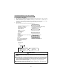
Thank you for choosing this Mitsubishi vector inverter. This Instruction Manual (detailed) provides instructions for advanced use of the
FR-V500 series inverters. Incorrect handling might cause an unexpected fault. Before using the inverter, always read this Instruction
Manual and the Instruction Manual (basic) [IB-0600064] packed with the product carefully to use the equipment to its optimum
performance.
This section is specifically about safety matters
Do not attempt to install, operate, maintain or inspect the inverter until you have read through the Instruction Manual (basic) and appended
documents carefully and can use the equipment correctly. Do not use the inverter until you have a full knowledge of the equipment, safety
information and instructions. In this Instruction Manual, the safety instruction levels are classified into "WARNING" and "CAUTION".
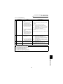
WARNING
CAUTION
Assumes that incorrect handling may cause hazardous conditions, resulting in death or severe injury.
Assumes that incorrect handling may cause hazardous conditions, resulting in medium or slight
injury, or may cause physical damage only.
CAUTION level may lead to a serious consequence according to conditions. Please follow the instructions of
Note that even the
both levels because they are important to personnel safety.
1. Electric Shock Prevention
WARNING
z While power is on or when the inverter is running, do not open the front cover. You may get an electric shock.
z Do not run the inverter with the front cover or wiring cover removed. Otherwise, you may access the exposed high-voltage terminals
or the charging part of the circuitry and get an electric shock.
z Even If power is off, do not remove the front cover except for wiring or periodic inspection. You may access the charged inverter
circuits and get an electric shock.
z Before starting wiring or inspection, check to make sure that the inverter power indicator lamp is off, wait for at least 10 minutes after
the power supply has been switched off, and check that there are no residual voltage using a tester or the like. The capacitor is
charged with high voltage for some time after power off and it is dangerous.
z This inverter must be earthed (grounded). Earthing (Grounding) must conform to the requirements of national and local safety
regulations and electrical codes. (NEC section 250, IEC 536 class 1 and other applicable standards).
z Any person who is involved in wiring or inspection of this equipment should be fully competent to do the work.
z Always install the inverter before wiring. Otherwise, you may get an electric shock or be injured.
z Perform setting dial and key operations with dry hands to prevent an electric shock.
z Do not subject the cables to scratches, excessive stress, heavy loads or pinching. Otherwise, you may get an electric shock.
z Do not change the cooling fan while power is on. It is dangerous to change the cooling fan while power is on.
2. Fire Prevention
CAUTION
z Install the inverter on an incombustible wall without holes, etc. Mounting it to or near combustible material can cause a fire.
z If the inverter has become faulty, switch off the inverter power. A continuous flow of large current could cause a fire.
z When a brake resistor is used, use an alarm signal to switch power off. Otherwise, the brake resistor will overheat abnormally due to
a brake transistor or other fault, resulting in a fire.
z Do not connect a resistor directly to the DC terminals P, N. This could cause a fire.
3.Injury Prevention
CAUTION
z Apply only the voltage specified in the instruction manual to each terminal to prevent damage etc.
z Ensure that the cables are connected to the correct terminals. Otherwise damage etc. may occur.
z Always make sure that polarity is correct to prevent damage etc.
z While power is on and for some time after power-off, do not touch the inverter or brake resistor as they are hot and you may get burnt.
4. Additional Instructions
Also note the following points to prevent an accidental failure, injury, electric shock, etc.
1) Transportation and installation
CAUTION
Environment
z When carrying products, use correct lifting gear to prevent injury.
z Do not stack the inverter boxes higher than the number recommended.
z Ensure that installation position and material can withstand the weight of the inverter. Install according to the information in the
instruction manual.
z Do not operate if the inverter is damaged or has parts missing.
z When carrying the inverter, do not hold it by the front cover; it may fall off or fail.
z Do not stand or rest heavy objects on the inverter.
z Check the inverter mounting orientation is correct.
z Prevent screws, wire fragments, other conductive bodies, oil or other flammable substances from entering the inverter.
z Do not drop the inverter, or subject it to impact
z Use the inverter under the following environmental conditions:
Ambient temperature
-10°C to +50°C (non-freezing)
Ambient humidity
90%RH or less (non-condensing)
Storage temperature
-20°C to +65°C*
Ambience
Indoors (free from corrosive gas, flammable gas, oil mist, dust and dirt)
Maximum 1000m above sea level for standard operation.
Altitude, vibration
After that derate by 3% for every extra 500m up to 2500m (91%). 5.9m/s2 or less
*Temperature applicable for a short time, e.g. in transit.
A-1
2) Wiring
CAUTION
z Do not fit capacitive equipment such as power factor correction capacitor, surge suppressor or radio noise filter (option FR-BIF) to
the inverter output side.
z The connection orientation of the output cables (terminals U, V, W) to the motor will affect the direction of rotation of the motor.
3) Trial run
CAUTION
z Check all parameters, and ensure that the machine will not be damaged by a sudden start-up.
4) Operation
WARNING
z When you have chosen the retry function, stay away from the equipment as it will restart suddenly after an alarm stop.
z Since the [STOP] key is valid only when functions are set (refer to page 115) provide a circuit and switch separately to make an
emergency stop (power off, mechanical brake operation for emergency stop, etc).
z Make sure that the start signal is off before resetting the inverter alarm. A failure to do so may restart the motor suddenly.
z The load used should be a three-phase induction motor only. Connection of any other electrical equipment to the inverter output may
damage the equipment.
z Do not modify the equipment.
z Do not perform parts removal which is not instructed in this manual. Doing so may lead to fault or damage of the inverter.
CAUTION
z The electronic thermal relay function does not guarantee protection of the motor from overheating.
z Do not use a magnetic contactor on the inverter input for frequent starting/stopping of the inverter.
z Use a noise filter to reduce the effect of electromagnetic interference. Otherwise nearby electronic equipment may be affected.
z Take measures to suppress harmonics. Otherwise power supply harmonics from the inverter may heat/damage the power capacitor
and generator.
z When a 400V class motor is inverter-driven, please use an insulation-enhanced motor or measures taken to suppress surge
voltages. Surge voltages attributable to the wiring constants may occur at the motor terminals, deteriorating the insulation of the
motor.
z When parameter clear or all clear is performed, each parameter returns to the factory setting. Each parameter returns to the factory
setting.
z The inverter can be easily set for high-speed operation. Before changing its setting, fully examine the performances of the motor and machine.
z In addition to the inverter's holding function, install a holding device to ensure safety.
z Before running an inverter which had been stored for a long period, always perform inspection and test operation. In addition to the
inverter's holding function, install a holding device to ensure safety.
5) Emergency stop
CAUTION
z Provide a safety backup such as an emergency brake which will prevent the machine and equipment from hazardous conditions if
the inverter fails.
z When the breaker on the inverter input side trips, check for the wiring fault (short circuit), damage to internal parts of the inverter, etc.
Identify the cause of the trip, then remove the cause and power on the breaker.
z When the protective function is activated, take the appropriate corrective action, then reset the inverter, and resume operation.
6) Maintenance, inspection and parts replacement
CAUTION
z Do not carry out a megger (insulation resistance) test on the control circuit of the inverter.
7) Disposing of the inverter
CAUTION
z Treat as industrial waste.
8) General instructions
Many of the diagrams and drawings in this Instruction Manual (basic) show the inverter without a cover, or partially open. Never operate
the inverter in this manner. Always replace the cover and follow this Instruction Manual (basic) when operating the inverter.
A-2
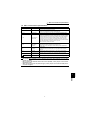
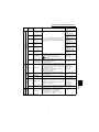
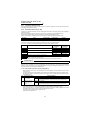
CONTENTS
WIRING
1
1.1
Internal block diagram......................................................................................... 2
1.2
Main circuit terminal specifications ................................................................... 3
1.3
Connection of stand-alone option units ............................................................ 4
1.3.1
1.3.2
1.3.3
1.3.4
1.3.5
1.3.6
1.4
Connection of the dedicated external brake resistor (FR-ABR) .........................................................4
Connection of the brake unit (FR-BU) ................................................................................................5
Connection of the brake unit (BU type) ..............................................................................................6
Connection of the high power factor converter (FR-HC) ....................................................................6
Connection of the power regeneration common converter (FR-CV) ..................................................7
Connection of the DC reactor (FR-HEL/BEL).....................................................................................7
Control circuit terminal specifications .............................................................. 8
1.4.1
Connecting the control circuit to a power supply separately from the main circuit...........................10
1.5
Precautions for use of the vector inverter....................................................... 11
1.6
Others ................................................................................................................. 12
1.6.1
1.6.2
1.6.3
1.6.4
1.6.5
1.6.6
1.6.7
1.6.8
1.6.9
1.7
Input terminals ................................................................................................... 26
1.7.1
1.7.2
1.7.3
1.7.4
1.7.5
1.7.6
1.7.7
1.8
Leakage currents and countermeasures..........................................................................................12
Power off and magnetic contactor (MC)...........................................................................................14
Installation of reactor ........................................................................................................................15
Notes on earthing (grounding)..........................................................................................................16
Inverter-generated noises and their reduction techniques ...............................................................17
Power supply harmonics ..................................................................................................................19
Harmonic suppression guidelines ....................................................................................................20
Inverter-driven 400V class motor .....................................................................................................22
Using the PU connector for computer link........................................................................................23
Run (start) and stop (STF, STR, STOP) ..........................................................................................26
External thermal relay input (OH).....................................................................................................27
Speed setting potentiometer connection (10E, 2 (1), 5)...................................................................27
Torque setting input signal and motor-generated torque (terminals 3, 5) ........................................28
Meter connection method and adjustment (DA1, DA2)....................................................................28
Common terminals (SD, 5, SE) ........................................................................................................29
Signal inputs by contact-less switches .............................................................................................29
How to use the input signals (assigned terminals DI1 to DI4, STR)
(Pr. 180 to Pr. 183, Pr. 187) ................................................................................ 30
1.8.1
1.8.2
1.8.3
1.8.4
1.8.5
1.8.6
1.8.7
1.8.8
1.8.9
1.8.10
1.8.11
1.8.12
Multi-speed setting (RL, RM, RH, REX signals): Pr. 180 to Pr. 183, Pr. 187 setting
"0, 1, 2, 8"
Remote setting (RL, RM, RH signals): Pr. 180 to Pr. 183, Pr. 187 setting "0, 1, 2" .........................30
Second function selection/second motor switchover (RT signal)
: Pr. 180 to Pr. 183, Pr. 187 setting "3" ............................................................................................30
Jog operation (jog signal): Pr. 180 to Pr. 183, Pr. 187 setting "5" ....................................................30
Third function selection (X9 signal): Pr. 180 to Pr. 183, Pr. 187 setting "9" .....................................31
FR-HC, FR-CV connection (X10 signal): Pr. 180 to Pr. 183, Pr. 187 setting "10"............................31
PU operation external interlock signal (X12 signal): Pr. 180 to Pr. 183, Pr. 187 setting "12"...........31
PID control enable terminal: Pr. 180 to Pr. 183, Pr. 187 setting "14" ...............................................31
Brake sequence opening signal (BRI signal): Pr. 180 to Pr. 183, Pr. 187 setting "15" ....................31
PU operation/external operation switchover: Pr. 180 to Pr. 183, Pr. 187 setting "16"......................31
S-pattern acceleration/deceleration C switchover terminal (X20 signal)
: Pr. 180 to Pr. 183, Pr. 187 setting "20" ..........................................................................................31
Orientation command (X22 signal): Pr. 180 to Pr. 183, Pr. 187 setting "22"....................................32
Pre-excitation/servo on (LX signal): Pr. 180 to Pr. 183, Pr. 187 setting "23" ...................................32
I
CONTENTS
1
1.8.13
1.8.14
1.8.15
1.8.16
1.8.17
1.8.18
1.8.19
1.9
Output stop (MRS signal): Pr. 180 to Pr. 183, Pr. 187 setting "24" ..................................................32
Start self-holding selection (STOP signal): Pr. 180 to Pr. 183, Pr. 187 setting "25".........................32
Control mode changing (MC signal): Pr. 180 to Pr. 183, Pr. 187 setting "26"..................................33
Torque limit selection (TL signal): Pr. 180 to Pr. 183, Pr. 187 setting "27" ......................................33
Start time tuning (X28 signal): Pr. 180 to Pr. 183, Pr. 187 setting "28" ............................................33
Torque bias selection 1 (X42 signal): Pr. 180 to Pr. 183, Pr. 187 setting "42"
Torque bias selection 2 (X43 signal): Pr. 180 to Pr. 183, Pr. 187 setting "43" .................................33
P control selection (P/PI control switchover) (X44 signal):
Pr. 180 to Pr. 183, Pr. 187 setting "44" ............................................................................................34
How to use the output signals (assigned terminals DO1 to DO3, ABC)
(Pr. 190 to Pr. 192, Pr. 195) ................................................................................ 35
1.10 Design information to be checked ................................................................... 37
1.11 Using the second motor .................................................................................... 38
1.11.1
1.11.2
Wiring diagram (second motor) ........................................................................................................38
Second motor setting parameters ...................................................................................................38
1.12 Using the conventional motor and other motors............................................ 39
1.12.1
1.12.2
2
Conventional motor (SF-VR, SF-JR with encoder) ..........................................................................39
Precautions for and wiring of the motor with encoder (SF-JR with encoder) ...................................40
VECTOR CONTROL
41
2.1
What is vector control? ..................................................................................... 42
2.2
Speed control ..................................................................................................... 44
2.2.1
2.2.2
2.3
Fine adjustment of gains for speed control .................................................... 45
2.3.1
2.3.2
2.3.3
2.3.4
2.3.5
2.4
Control block diagram ......................................................................................................................52
Gain adjustment for torque control.................................................................. 53
2.6.1
2.6.2
2.6.3
2.7
Outline of torque control ...................................................................................................................51
Fine adjustment for torque control .................................................................. 52
2.5.1
2.6
Control block diagram ......................................................................................................................45
Concept of adjustment of manual input speed control gains............................................................46
Speed control gain adjustment procedure (Pr. 820, Pr. 821) ...........................................................46
Troubleshooting................................................................................................................................47
Speed feed forward control, model adaptive speed control (Pr. 828, Pr. 877 to Pr. 881) ................49
Torque control.................................................................................................... 51
2.4.1
2.5
Outline of speed control ...................................................................................................................44
Easy gain tuning function block diagram..........................................................................................44
Concept of torque control gains .......................................................................................................53
Gain adjustment procedure ..............................................................................................................53
Troubleshooting................................................................................................................................54
Position control (Pr. 419 to Pr. 430, Pr. 464 to Pr. 494) .................................. 55
2.7.1
2.7.2
2.7.3
2.7.4
2.7.5
2.7.6
2.7.7
2.7.8
Connection diagram .........................................................................................................................55
Position control step .........................................................................................................................56
Control block diagram ......................................................................................................................57
Parameter.........................................................................................................................................57
Conditional position feed function by contact input (Pr. 419 = 0) .....................................................59
Setting the electronic gear................................................................................................................60
In-position width (Pr. 426) ................................................................................................................62
Excessive level error (Pr. 427) .........................................................................................................62
II
3
Pulse monitor selection (Pr. 430) .....................................................................................................62
Concept of position control gains .....................................................................................................62
Troubleshooting................................................................................................................................63
Position control is not exercised normally ........................................................................................64
PARAMETERS
65
3.1
Parameter list ..................................................................................................... 66
3.2
At-a-glance guide to functions ......................................................................... 73
3.3
Basic functions (Pr. 0 to Pr. 9) .......................................................................... 76
3.3.1
3.3.2
3.3.3
3.3.4
3.3.5
3.3.6
3.4
Standard operation functions (Pr. 10 to Pr. 16) .............................................. 82
3.4.1
3.4.2
3.4.3
3.5
Monitor display/DA1, DA2 terminal function selection (Pr. 52 to Pr. 54, Pr. 158) ...........................97
Monitoring reference (Pr. 55, Pr. 56, Pr. 866) ................................................................................100
Automatic restart (Pr. 57, Pr. 58) .................................................................... 101
3.8.1
3.9
Up-to-speed sensitivity (Pr. 41) ........................................................................................................95
Speed detection (Pr. 42, Pr. 43, Pr. 50, Pr. 116)..............................................................................95
Display functions 1 (Pr. 52 to Pr. 56)................................................................ 97
3.7.1
3.7.2
3.8
Inverter output stop (MRS) (Pr. 17) ..................................................................................................86
Torque limit (Pr. 22, Pr. 803, Pr. 810 to Pr. 817)............................................................................87
RH, RM, RL signal input compensation (Pr. 28) ..............................................................................88
S-pattern acceleration/deceleration curve (Pr. 29, Pr. 140 to Pr. 143, Pr. 380 to Pr. 383) ..............89
Regenerative brake duty (Pr. 30, Pr. 70)..........................................................................................92
Speed jump (Pr. 31 to Pr. 36)...........................................................................................................93
Speed display (Pr. 37, Pr. 144, Pr. 505 )..........................................................................................93
Output terminal functions (Pr. 41 to Pr. 50)..................................................... 95
3.6.1
3.6.2
3.7
DC injection brake operation (Pr. 10, Pr.11, Pr. 12, Pr.802) ...........................................................82
Starting speed (Pr. 13) .....................................................................................................................84
Jog operation (Pr. 15, Pr. 16) ...........................................................................................................85
Operation selection functions 1 (Pr. 17 to Pr. 37) ........................................... 86
3.5.1
3.5.2
3.5.3
3.5.4
3.5.5
3.5.6
3.5.7
3.6
Torque boost (Pr. 0) .........................................................................................................................76
Maximum and minimum speed settings (Pr. 1 , Pr. 2) ....................................................................76
Base frequency, base frequency voltage (Pr. 3, Pr. 19)...................................................................77
Multi-speed operation (Pr. 4 to Pr. 6, Pr. 24 to Pr. 27, Pr. 232 to Pr. 239)......................................77
Acceleration and deceleration time (Pr. 7, Pr. 8, Pr. 20, Pr. 21, Pr. 44, Pr. 45, Pr. 110, Pr. 111) ...78
Motor overheat protection (Pr. 9, Pr. 452, Pr. 876 ) .........................................................................80
Automatic restart after instantaneous power failure (Pr. 57, Pr. 58, Pr. 162 to Pr. 165) ................101
Additional functions (Pr. 59) ........................................................................... 103
3.9.1
Remote setting function selection (Pr. 59 ) ....................................................................................103
3.10 Brake sequence (Pr. 60, Pr. 278 to Pr. 285) ................................................... 106
3.10.1
Brake sequence function (Pr. 60, Pr. 278 to Pr. 285).....................................................................106
3.11 Operation selection function 2 (Pr. 65 to Pr. 79) ........................................... 109
3.11.1
3.11.2
3.11.3
3.11.4
3.11.5
3.11.6
Retry function (Pr. 65, Pr. 67 to Pr. 69) ..........................................................................................109
Applied motor (Pr. 71, Pr. 450).......................................................................................................111
PWM carrier frequency selection (Pr. 72, Pr. 240).........................................................................112
Speed setting signal on/off selection (Pr. 73).................................................................................113
Reset selection/disconnected PU detection/PU stop selection (Pr. 75) .........................................115
Parameter write disable selection (Pr. 77) .....................................................................................116
III
CONTENTS
2.7.9
2.7.10
2.7.11
2.7.12
3.11.7
3.11.8
Reverse rotation prevention selection (Pr. 78 ) ..............................................................................117
Operation mode selection (Pr. 79) .................................................................................................117
3.12 Offline auto tuning (Pr. 80 to Pr. 96)............................................................... 120
3.12.1
3.12.2
3.12.3
3.12.4
3.12.5
3.12.6
Offline auto tuning function
(Pr. 9, Pr. 80, Pr. 81, Pr. 83, Pr. 84, Pr. 71, Pr. 96, Pr. 450, Pr. 452).............................................120
Parameters.....................................................................................................................................120
Execution of offline auto tuning ......................................................................................................121
Utilizing or changing offline auto tuning data for use......................................................................123
Setting the motor constants directly ...............................................................................................124
Direct input + offline auto tuning.....................................................................................................125
3.13 Online auto tuning (Pr. 95) .............................................................................. 126
3.13.1
Online auto tuning selection (Pr. 95, Pr. 9, Pr. 71, Pr. 80, Pr. 81 ).................................................126
3.14 Communication functions (Pr. 117 to Pr. 124, Pr. 342) ................................ 128
3.14.1
3.14.2
Computer link operation (RS-485 communication) (Pr. 117 to Pr. 124)........................................128
E2PROM write selection (Pr. 342) .................................................................................................139
3.15 PID control (Pr. 128 to Pr. 134) ....................................................................... 139
3.15.1
PID control (Pr. 128 to Pr. 134) ......................................................................................................139
3.16 Current detection (Pr. 150 to Pr. 153)............................................................. 146
3.16.1
3.16.2
Output current detection function (Pr. 150, Pr. 151).......................................................................146
Zero current detection (Pr. 152, Pr. 153)........................................................................................147
3.17 Auxiliary functions (Pr. 156, Pr. 157).............................................................. 148
3.17.1
3.17.2
Stall prevention operation selection (Pr. 156) ................................................................................148
OL signal output timer (Pr. 157) .....................................................................................................149
3.18 Display function 3 (Pr. 160) ............................................................................. 150
3.18.1
Extended function display selection (Pr. 160) ................................................................................150
3.19 Initial monitor (Pr. 171) .................................................................................... 150
3.19.1
Actual operation hour meter clear (Pr. 171) ...................................................................................150
3.20 Terminal assignment functions (Pr. 180 to Pr. 195) ..................................... 150
3.20.1
3.20.2
Input terminal function selection (Pr. 180 to Pr. 183, Pr. 187).......................................................150
Output terminal function selection (Pr. 190 to Pr. 192, Pr. 195).....................................................152
3.21 Auxiliary function (Pr. 244) ............................................................................. 154
3.21.1
Cooling fan operation selection (Pr. 244) .......................................................................................154
3.22 Stop selection function (Pr. 250) .................................................................... 154
3.22.1
Stop selection (Pr. 250)..................................................................................................................154
3.23 Operation selection function (Pr. 251) ........................................................... 155
3.23.1
Output phase failure protection selection (Pr. 251) ........................................................................155
3.24 Additional function 2 (Pr. 252, Pr. 253) .......................................................... 156
3.24.1
Override bias, gain (Pr. 252, Pr. 253).............................................................................................156
3.25 Power failure stop functions (Pr. 261 to Pr. 266) .......................................... 156
3.25.1
Power-failure deceleration stop function (Pr. 261 to Pr. 266).........................................................156
3.26 Droop (Pr. 286 to Pr. 288) ................................................................................ 158
3.26.1
Droop control (Pr. 286 to Pr. 288) ..................................................................................................158
3.27 Orientation (Pr. 350 to Pr. 362, Pr. 393 to Pr. 399) ........................................ 159
3.27.1
Orientation control (Pr. 350, Pr. 351, Pr. 356, Pr. 357, Pr. 360 to Pr. 362, Pr. 393,
Pr. 396 to Pr. 399) .........................................................................................................................159
IV
3.28 Control system function (Pr. 374) .................................................................. 166
Overspeed detection (Pr. 374) .......................................................................................................166
3.29 Position control (Pr. 419 to Pr. 430, Pr. 464 to Pr. 494) ................................ 167
3.29.1
Position control (Pr. 419 to Pr. 430, Pr. 464 to Pr. 494) .................................................................167
3.30 Remote output (Pr. 495 to Pr.497) .................................................................. 168
3.30.1
Remote output function (Pr. 495 to Pr.497)....................................................................................168
3.31 Operation selection functions 4 (Pr. 800 to Pr. 809) ..................................... 169
3.31.1
3.31.2
3.31.3
3.31.4
Control selection (Pr. 800, Pr. 451) ................................................................................................169
Torque characteristic selection (Pr. 801)........................................................................................169
Torque command source selection (Pr. 804 to Pr. 806).................................................................171
Speed limit (Pr. 807 to Pr. 809) ......................................................................................................173
3.32 Control system functions (Pr. 818 to Pr. 837) ............................................... 175
3.32.1
3.32.2
3.32.3
3.32.4
3.32.5
3.32.6
3.32.7
3.32.8
3.32.9
3.32.10
Easy gain tuning selection (Pr. 818, Pr. 819) .................................................................................175
Speed loop proportional gain setting (Pr. 820, Pr. 830) .................................................................175
Speed control integral time setting (Pr. 821, Pr. 831) ....................................................................175
Speed setting circuit filter function (Pr. 822, Pr. 832) .....................................................................175
Speed detection filter function (Pr. 823, Pr. 833) ...........................................................................176
Current loop proportional gain setting for vector control (Pr. 824, Pr. 834)...................................176
Current control integral time setting for vector control (Pr. 825, Pr. 835) ......................................176
Torque setting filter function (Pr. 826, Pr. 836) ..............................................................................176
Torque detection filter function (Pr. 827, Pr. 837) ..........................................................................177
Model speed control gain (Pr. 828) ................................................................................................177
3.33 Torque biases (Pr. 840 to Pr. 848) .................................................................. 177
3.33.1
Torque bias function (Pr. 840 to Pr. 848) .......................................................................................177
3.34 Additional functions (Pr. 851 to Pr. 865) ........................................................ 180
3.34.1
3.34.2
3.34.3
3.34.4
3.34.5
3.34.6
Selection of number of encoder pulses (Pr. 851) ...........................................................................180
Selection of encoder rotation direction (Pr. 852) ............................................................................180
Excitation ratio (Pr. 854).................................................................................................................181
Notch filter (Pr. 862, Pr. 863)..........................................................................................................181
Torque detection (Pr. 864) .............................................................................................................182
Low speed detection (Pr. 865) .......................................................................................................182
3.35 Display function (Pr. 867) ................................................................................ 183
3.35.1
DA1 output response level adjustment (Pr. 867)............................................................................183
3.36 Terminal function assignment (Pr. 868)......................................................... 183
3.36.1
Terminal 1 function assignment (Pr. 868) ......................................................................................183
3.37 Protective functions (Pr. 870 to Pr. 874) ........................................................ 184
3.37.1
3.37.2
3.37.3
Speed deviation excessive (Pr. 870, Pr. 871) ................................................................................184
Speed limit (Pr. 873).......................................................................................................................185
Stop by OLT level prevention (Pr. 874) ..........................................................................................185
3.38 Operation selection functions 5 (Pr. 875) ...................................................... 186
3.38.1
Fault definition (Pr. 875) .................................................................................................................186
3.39 Control system function 2 (Pr. 877 to Pr. 881) .............................................. 186
3.39.1
Speed feed forward control, model adaptive speed control (Pr. 877 to Pr. 881)...........................186
3.40 Maintenance function (Pr. 890 to Pr. 892)...................................................... 187
3.40.1
Maintenance output function (Pr. 890 to Pr. 892)...........................................................................187
3.41 Calibration functions (Pr. 900 to Pr. 920)....................................................... 188
V
CONTENTS
3.28.1
3.41.1
3.41.2
DA1/DA2 terminal calibration (Pr. 900, Pr. 901).............................................................................188
Biases and gains of speed setting terminals
(speed setting terminal 2, torque command terminal 3, multi function terminal 1)
(Pr. 902 to Pr. 905, Pr. 917 to Pr. 920)...........................................................................................190
3.42 Additional function (Pr. 990) ........................................................................... 193
3.42.1
4
PU buzzer control (Pr. 990)............................................................................................................193
SPECIFICATIONS
195
4.1
Model specifications........................................................................................ 196
4.2
Common specifications .................................................................................. 199
4.3
Outline dimension drawings........................................................................... 200
4.3.1
4.3.2
4.3.3
4.3.4
4.3.5
Inverter outline dimension drawings...............................................................................................200
Control panel (FR-DU04-1) outline dimension drawings................................................................203
Parameter unit (FR-PU04V) outline dimension drawings...............................................................203
Dedicated encoder cable outline dimension drawings ...................................................................204
Dedicated motor outline dimension drawings.................................................................................206
APPENDICES
211
Appendix1 Setting a thermistor of a dedicated motor (SF-V5RU*****T)
(when used with the FR-V5AX).......................................................................... 212
Appendix2
Parameter Instruction Code List ............................................................. 213
Appendix3
SERIAL number check............................................................................ 220
VI
1
WIRING
This chapter describes the basic "wiring" for use of this
product.
Always read the instructions and other information before
using the equipment.
1.1
1.2
1.3
1.4
1.5
1.6
1.7
1.8
Internal block diagram ..........................................2
Main circuit terminal specifications ....................3
Connection of stand-alone option units..............4
Control circuit terminal specifications................8
Precautions for use of the vector inverter ..........11
Others.....................................................................12
Input terminals ......................................................26
How to use the input signals (assigned terminals
DI1 to DI4, STR) (Pr. 180 to Pr. 183, Pr. 187)...........30
1.9 How to use the output signals (assigned terminals
DO1 to DO3, ABC) (Pr. 190 to Pr. 192, Pr. 195)........ 35
1.10 Design information to be checked ......................37
1.11 Using the second motor .......................................38
1.12 Using the conventional motor and other motors .. 39
<Abbreviations>
DU : Control panel (FR-DU04-1)
PU : Control panel (FR-DU04-1) and parameter unit (FR-PU04V)
Inverter : Mitsubishi vector inverter FR-V500 series
Pr. : Parameter number
PU operation : Operation using the PU (FR-DU04-1/FR-PU04V)
External operation : Operation using the control circuit signals
Combined operation : Operation using both the PU (FR-DU04-1/FR-PU04V) and external
operation
Mitsubishi dedicated motor : SF-V5R
Mitsubishi standard motor with encoder : SF-JR
Mitsubishi constant-torque motor : SF-HRCA
<Trademarks>
CC-Link is a registered trademark of CC-Link Partner Association.
Ethernet is a registered trademark of XEROX corporation.
DeviceNet is a registered trademark of ODVA (Open DeviceNet Vender Association, Inc.)
Profibus is a registered trademark of PROFIBUS User Organization.
Other company and product names herein are the trademarks or registerd trademarks of
their respective owners.
1
2
3
4
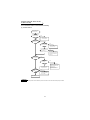
1
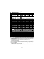
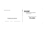
Internal block diagram
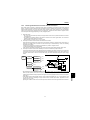
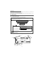
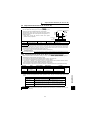
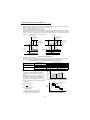
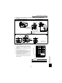
1.1 Internal block diagram
Verify the power specification
of the motor cooling fan when
performing wiring.
Refer to page 196.
B
T
C
FR-V500
R
S
T
A
S
Avoid frequent ON-OFF.
Repeated inrush current at power on
will shorten the converter life.
(switching life is about 100,000 times)
MCCB MC
OCR
MCCB MC
R
Mitsubishi dedicated
motor (SF-V5RU)
P1
Jumper: Remove this jumper when connecting
the FR-HEL/BEL.
Jumper: Remove this jumper when
connecting the FR-ABR.
(5.5K or less only)
PR
P
N
PX
U
V
*
*
R
W
TR
FAN
CAUTION
Match the phase
sequence. (The fan
should have intake
rotation.)
U
V
W
IM
Jumper
R1
S1
Control
power
supply
CHARGE
ASIC
Change the jumper
connector and parameter
according to the encoder
specifications.
Protective
circuit
CMP
5.5V12V 24V EXT
LDV
PG
S
PA
A
PAR
B
PB
C
PBR
D
PZ
F
5
PZR
G
3
SD
R
RS485
TA
DU04-1
TB
10E
Output speed
setting
potentiometer
Analog common
0 to 10VDC
0 to
10VDC
Encoder
10V
2
CPU
TZ
G2
1
OH
G1
Thermal* *
protector
ASIC
DA1
DA2
External transistor PC
common
SD
RA
SINK
SOURCE
B
Alarm output
C
Three different
DO1 signals can be
DO2 selected using the
parameters.
DO3 (Open collector
output)
SE
STF
STR
RES
DI1
DI3
DI4
OPTION
#3
DI2
OPTION
#2
Reset
Multi-function
input 4
Four different
signals can be
selected using
the parameters.
A
OPTION
#1
Forward rotation
Reverse rotation
Analog
signal output
CAUTION
1.
2.
3.
The 18.5K or more is not equipped with the built-in brake resistor and brake transistor marked *. The brake transistor is
provided for the 15K or less and the built-in brake resistor for the 5.5K or less.
Always earth (ground) the inverter and motor.
**: When using an external thermal relay protection, set "1" (external thermal relay valid) in Pr. 876. (factory setting)
(Refer to page 80.)
2
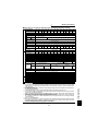
Main circuit terminal specifications
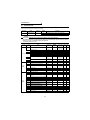
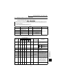
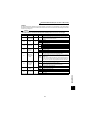
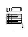
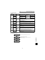
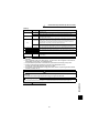
1.2 Main circuit terminal specifications
Terminal Symbol
Terminal Name
DC reactor
connection
Built-in brake circuit
connection
Connect to the commercial power supply.
Keep these terminals open when using the high power factor converter (FRHC) or power regeneration common converter (FR-CV).
Connect a three-phase squirrel-cage motor or Mitsubishi dedicated motor.
Connected to the AC power supply terminals R and S. To retain the alarm
display and alarm output or when using the high power factor converter (FRHC) or power regeneration common converter (FR-CV), remove the jumpers
from terminals R-R1 and S-S1 and apply external power to these terminals.
Do not turn off the power supply for control circuit (R1, S1) with the main
circuit power (R, S, T) on. Doing so may damage the inverter. The circuit
should be configured so that the main circuit power (R, S, T) is also turned off
when the power supply for control circuit (R1, S1) is off.
15K or less: 60VA, 18.5K to 55K: 80VA
Disconnect the jumper from terminals PR-PX (5.5K or less) and connect the
optional brake resistor (FR-ABR) across terminals P-PR.
For the 15K or less, connecting the resistor further provides regenerative
braking power.
Connect the optional FR-BU type brake unit, BU type brake unit, power
regeneration common converter (FR-CV) or high power factor converter
(FR-HC).
Disconnect the jumper from terminals P-P1 and connect the optional DC
reactor (FR-HEL/BEL).
When the jumper is connected across terminals PX-PR (factory setting),
the built-in brake circuit is valid. (Provided for the 5.5K or less.)
Earth (Ground)
For earthing (grounding) the inverter chassis. Must be earthed (grounded).
R, S, T
AC power input
U, V, W
Inverter output
R1, S1
Power supply for
control circuit
P, PR
Brake resistor
connection
P, N
Brake unit
connection
P, P1
PR, PX
Description
CAUTION
• The inverter will be damaged if power is applied to the inverter output terminals (U, V, W). Never
perform such wiring.
• When connecting the dedicated external brake resistor (FR-ABR), remove jumpers across terminals
PR-PX (5.5K or less).
• When connecting the brake unit (FR-BU, BU type), remove jumpers across terminals PR-PX (5.5K or
less). Refer to page 5, 6.
WIRING
1
3
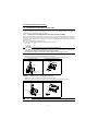
Connection of stand-alone option units
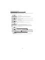
1.3 Connection of stand-alone option units
The inverter accepts a variety of stand-alone option units as required.
Incorrect connection will cause inverter damage or accident. Connect and operate the option unit carefully in
accordance with the corresponding option unit manual.
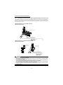
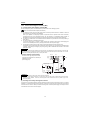
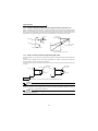
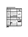
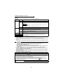
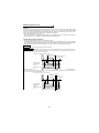
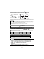
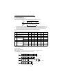
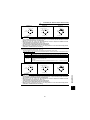
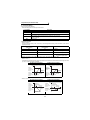
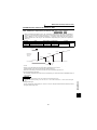
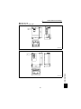
1.3.1
Connection of the dedicated external brake resistor (FR-ABR)
The built-in brake resistor is connected across terminals P and PR. Fit the external dedicated brake resistor (FRABR) when the built-in brake resistor does not have enough thermal capability for high-duty operation. At this time,
remove the jumper from across terminals PR-PX and connect the dedicated brake resistor (FR-ABR) across
terminals P-PR.
Set "1" in Pr. 30 "regenerative function selection".
Set Pr.70 "special regenerative brake duty" as follows: (Refer to page 92.)
7.5K or less. . . . . . .10%
11K or more . . . . . .6%
CAUTION
1. The brake resistor connected should only be the dedicated brake resistor.
2. The jumper across terminals PR-PX (5.5K or less) must be disconnected before connecting the
dedicated brake resistor. A failure to do so may damage the inverter.
3. Do not remove a jumper across terminal P and P1 except when connecting a DC reactor.
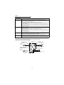
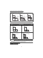
z Model ..... FR-V520-1.5K, 2.2K, FR-V540-1.5K, 2.2K
1)Remove the screws in terminals PR and PX and remove the jumper.
2)Connect the brake resistor across terminals P and PR. (The jumper should remain disconnected.)
1) Removal of jumper
2) Connection of brake resistor
Terminal P
Terminal PR
Terminal PR
Jumper
Terminal PX
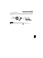
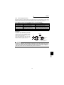
z Model ..... FR-V520-3.7K to 7.5K, FR-V540-3.7K, 5.5K
1)Remove the screws in terminals PR and PX and remove the jumper.
2)Connect the brake resistor across terminals P and PR. (The jumper should remain disconnected.)
1) Removal of jumper
2) Connection of brake resistor
Terminal P
Terminal PR
Terminal PR
Terminal PX
Terminal PX
Jumper
CAUTION
The FR-V520-7.5K does not have the PX terminal. Since it is a free terminal, keep it open.
4
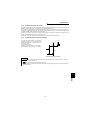
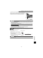
Connection of stand-alone option units
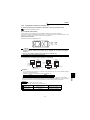
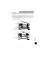
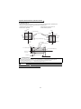
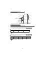
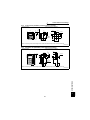
z Model ..... FR-V520-11K to 15K, FR-V540-7.5K to 15K
1) Connect the brake resistor across terminals P and PR.
R1 S1
PR
R
S
T
U
V
Power supply terminal
block for control circuit
W
P1
N
P
Dedicated brake resistor
(FR-ABR)
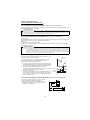
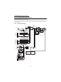
1.3.2
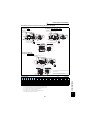
Connection of the brake unit (FR-BU)
Connect the optional FR-BU brake unit as shown below to improve the braking capability during deceleration.
T *2
ON
MC
U
Motor
S
V
IM
T
W
R
Power
supply
*3
Remove
jumper.
Inverter
PR
P
PX
N
MC
OFF
MC
PR
PR
P
*1
N
*4
P
HA
HB
TH1
HC
THS TH2
*1
*2
*3
*4
Resistor unit
FR-BR
Connect the inverter terminals (P, N) and brake unit (FR-BU (H)) terminals so that their terminal signals match with each other.
(Incorrect connection will damage the inverter.)
When the power supply is 400V class, install a step-down transformer.
Be sure to remove a jumper across terminal PR-PX when using the FR-BU with the inverter of 5.5K or less.
The wiring distance between the inverter, brake unit (FR-BU) and resistor unit (FR-BR) should be within 5m. If twisted wires
are used, the distance should be within 10m.
CAUTION
• If the transistors in the brake unit should become faulty, the resistor can be unusually hot, causing a
fire. Therefore, install a magnetic contactor on the inverter's input side to configure a circuit so that a
current is shut off in case of fault.
• Do not remove a jumper across terminal P and P1 except when connecting a DC reactor.
5
1
WIRING
Brake unit
FR-BU
Connection of stand-alone option units
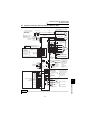
1.3.3
Connection of the brake unit (BU type)
Connect the BU type
brake unit correctly as
shown on the right.
Incorrect connection will
damage the inverter.
Remove the jumpers
from terminals HB-PC
and TB-HC and fit a
jumper across terminals
PC-TB of the brake unit.
MCCB
Inverter
MC
Power
supply
U
S
V
T
W
Motor
IM
PR
Remove
jumpers.
*3
T *2
R
PX
P
N
*1
MC
ON
Discharging resistor
OFF
Remove
jumpers.
MC
Fit a jumper.
PC HA HB HC
TB
P
N
PR
OCR
OCR
BU type brake unit
*1
*2
*3
Connect the inverter terminals (P, N) and brake unit (BU type) terminals so that their terminal signals match with each
other. (Incorrect connection will damage the inverter.)
When the power supply is 400V class, install a step-down transformer.
For capacity 5.5K or less, remove the jumper across terminals PR-PX.
CAUTION
• The wiring distance between the inverter, brake unit and resistor unit should be within 2m . If twisted
wires are used, the distance should be within 5m.
• If the transistors in the brake unit should become faulty, the resistor can be unusually hot, causing a
fire. Therefore, install a magnetic contactor on the inverter's power supply side to configure a circuit
so that a current is shut off in case of fault.
• Do not remove a jumper across terminal P and P1 except when connecting a DC reactor.
1.3.4
Connection of the high power factor converter (FR-HC)
When connecting the high power factor converter (FR-HC) to suppress power supply harmonics, perform wiring
securely as shown below. Incorrect connection will damage the high power factor converter and inverter.
After making sure that the wiring is correct, set "2" in Pr. 30 "regenerative function selection".
High power factor converter (FR-HC)
R
S
T MC1MC2 R4
R4
S4
T4
S4
N
P
S3
MCCB
S2
S
*2
*3
R
S *1
X10 *3
X11 *3
N
*2
P
R1
*1
S1
T2
T
Power
supply
*1
SE
RES
T3
FR-HCL01
R
Inverter
RSO
SD
MC2
Outside box
MC1
R2
RDY
T
T4
From FR-HCL02
R3
Y1 or Y2
Remove the jumpers across the inverter terminals R-R1, S-S1, and connect the control circuit power supply to the R1
and S1 terminals. Always keep the power input terminals R, S, T open. Incorrect connection will damage the inverter.
(E.OPT (option alarm) will occur. (Refer to the Instruction Manual (basic).))
Do not insert the MCCB between terminals P-N (P-P, N-N). Connect the inverter terminals (P, N) and high power factor converter
(FR-HC) terminals so that their terminal signals match with each other. (Incorrect connection will damage the inverter.)
Use Pr. 180 to Pr. 183, Pr. 187 (input terminal function selection) to assign the terminals used for the X10 (X11) signal. (Refer to
page 150.)
For communication where the start command is sent only once, e.g. when used with the computer link plug-in option (A5NR),
use the X11 signal when making setting to hold the mode at occurrence of an instantaneous power failure. (Refer to page 92.)
CAUTION
• The voltage phases of terminals R, S, T and terminals R4, S4, T4 must be matched.
• Use sink logic (factory setting) when the FR-HC is connected. The FR-HC cannot be connected when
source logic is selected.
• Do not remove a jumper across terminal P and P1 except when connecting a DC reactor.
6
Connection of stand-alone option units
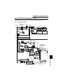
1.3.5
Connection of the power regeneration common converter (FR-CV)
When connecting the FR-CV type power regeneration common converter, connect the inverter terminals (P, N) and
FR-CV type power regeneration common converter terminals as shown below so that their symbols match with
each other. After making sure that the wiring is correct, set "2" in Pr. 30 "regenerative function selection". Use the
FR-CV with capacity one rank greater than the inverter.
MCCB
Three-phase
AC power
supply
MC1
Dedicated stand-alone
reactor (FR-CVL)
R/L11
S/L21
T/L31
R
S *1
T
U
R1
S1
W
FR-CV power regeneration
common converter
R2/L12
S2/L22
T2/L32
R2/L1
S2/L2
T2/L3
*4
R/L11
S/L21
T/MC1
V
Inverter
P/L+
N/L-
P
*2
N
P24
PC
SD
RDYA
SD
RDYB
X10 *3
RSO
IM
RES
SE
*1
*2
*3
*4
Remove the jumpers across terminals R-R1 and S-S1 of the inverter, and connect the control circuit power supply across
terminals R1-S1. Always keep the power input terminals R, S, T open. Incorrect connection will damage the inverter.
(E.OPT (option alarm) will occur. (Refer to the Instruction Manual (basic).))
Do not insert an MCCB between the terminals P − N (between P/L+ − P, between N/L- − N). Connect the inverter terminals
(P, N) and power regeneration common converter (FR-CV) terminals so that their terminal signals match with each other.
(Incorrect connection will damage the inverter.).
Assign the terminal for X10 signal using any of Pr. 180 to Pr. 183. Pr.187 (input terminal function selection).
(Refer to page 150)
Be sure to connect the power supply and terminals R/L11, S/L21, T/MC1.
Operating the inverter without connecting them will damage the power regeneration common converter.
CAUTION
1. The voltage phases of terminals R/L11, S/L21, T/MC1 and terminals R2/L1, S2/L2, T2/L3 must be
matched.
2. Use sink logic (factory setting) when the FR-CV is connected. The FR-CV cannot be connected when
source logic is selected.
3. Do not remove a jumper across terminal P and P1 except when connecting a DC reactor.
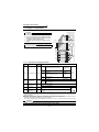
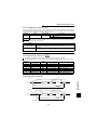
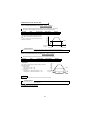
1.3.6
Connection of the DC reactor (FR-HEL/BEL)
When using the FR-HEL/BEL DC reactor, connect it between terminals P1-P. In this case, the jumper connected
across terminals P1-P must be removed. Otherwise, the reactor will not exhibit its function.
P
FR-HEL/BEL
Remove
the jumper.
CAUTION
1. The wiring distance should be within 5m.
2. The size of the cables used should be equal to or larger than that of the power supply cables (R, S, T).
7
1
WIRING
P1
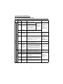
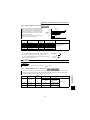
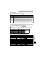
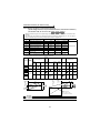
Control circuit terminal specifications
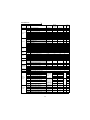
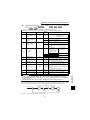
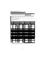
1.4 Control circuit terminal specifications
Type
Terminal
Symbol
STF
Forward rotation
start
STR
Reverse rotation
start
DI1 to DI4
Digital input
terminals 1 to 4
OH
Thermal relay
protector input
RES
Reset
SD
Contact input
common (sink)
PC
24VDC power
supply and
external transistor
common, contact
input common
(source)
10E
Speed setting
power supply
2
Speed setting
(voltage)
3
Torque setting
terminal
1
Multi-function
setting terminal
5
Speed setting
common, Analog
signal output
common
Contact input
Speed setting
Input signals
Terminal Name
Description
Rated Specifications
Turn on the STF signal to start
forward rotation and turn it off to
stop.
When the STF and
Turn on the STR signal to start
STR signals are
reverse rotation and turn it off to
turned on
stop.
simultaneously, the
The function of the terminals
stop command is
changes according to the output
given.
terminal function selection
(Pr. 187).
Refer to page 150 for details.
The function of the terminals changes according to the
output terminal function selection (Pr. 180 to Pr. 183).
Refer to page 150 for details.
Input resistance 4.7kΩ
Voltage at opening 21 to
27VDC
Current at short-circuited
4 to 6mADC
Control by open collector
output or 0V contact
signal
Input resistance 150kΩ
Voltage at opening 21 to
Temperature sensor terminal input for motor overheat
27VDC
protection.
Current at short-circuited
OHT error occurs when terminals OH and SD are open.
140 to 180mADC
Isolate by photocoupler
Input resistance 4.7kΩ
Voltage at opening 21 to
Used to reset alarm output provided when protective
27VDC
circuit is activated. Turn on the RES signal for more than Current at short-circuited
0.1s, then turn it off.
4 to 6mADC
Recover about 1s after reset is cancelled.
Control by open collector
output or 0V contact
signal.
Contact input common terminal. Common output
terminal for 24VDC 0.1A power supply (PC terminal).
—
Isolated from terminals 5 and SE.
When connecting a transistor output (open collector
output) such as a programmable controller, connect the
external power supply common for transistor output to
Voltage range 18 to 26
this terminal to prevent a malfunction caused by a sneak
VDC
current. PC-SD can be used as a 24VDC and 0.1A
Permissible load current
power supply. Note that a sneak current may not be
0.1A
prevented in this case. When source logic has been
selected, this terminal serves as a contact input
common.
Used as power supply when connecting volume for
10VDC±0.4V
speed setting (torque setting) from outside of the
Permissible load current
inverter. (terminal 5 is a common terminal)
10mA
By entering 0 to 10VDC, the maximum output speed is
reached at 10V and I/O are proportional.
Acts as a torque setting signal for torque control or as a
torque limit signal for speed control or position control.
Input resistance
Acts as an input terminal for the external analog-based
10kΩ±1kΩ
torque bias function.
Permissible maximum
0 to ±10VDC input
voltage 20VDC
Since this is a multi-function selection terminal, its
function varies with the Pr.868 "terminal 1 function
assignment" setting. Refer to page 183 for details.
0 to ±10VDC input
Common terminal for speed setting signal (terminal 2, 1
or 3) or DA1 and DA2.
—
Isolated from terminals SD and SE. Do not earth
(ground).
8
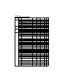
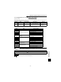
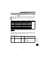
Control circuit terminal specifications
Terminal
Symbol
PAR
Encoder signal
Input signals
PB
PBR
PZ
PZR
PG
Analog
Open
collector
Contact
SD
Output signals
A, B, C
DO1 to
DO3
SE
DA1, DA2
5
RS-485
Description
Rated Specifications
Differential line receiver
input (AM26LS32
equivalent) or
complimentary input
A-phase inverted
Differential line receiver
signal input
input (AM26LS32
terminal
equivalent)
Differential line receiver
A-, B- and Z-phase signals are input from the encoder. input (AM26LS32
B-phase signal
The jumper connector is factory-set to complimentary. equivalent) or
input terminal
Thus, the encoder need not be connected to PAR, PBR complimentary input
and PZR.
B-phase inverted
Differential line receiver
signal input
input (AM26LS32
terminal
equivalent)
Differential line receiver
Z-phase signal
input (AM26LS32
input terminal
equivalent) or
complimentary input
Z-phase inverted
Differential line receiver
signal input
input (AM26LS32
terminal
equivalent)
Power supply for encoder. You can switch the power
supply between 5 (5.5), 12 and 24VDC. Can be
Encoder power
5.5VDC 350mA
switched to the external power supply.
supply terminal
12VDC 150mA
(Positive side)
24VDC 80mA
(
Refer to the instruction manual (basic) for the
switchover method.)
Contact input
Common terminal for contact input or encoder power
common (sink),
supply.
Power supply common
Power supply earth Isolated from terminals 5 and SE.
(ground) terminal Do not earth (ground).
1 changeover contact output indicating that the output
has been stopped by the inverter protective function.
230VAC 0.3A, 30VDC 0.3A. Alarm: discontinuity across Contact output
B-C (continuity across A-C), normal: continuity across
Permissible contact
Alarm output
B-C (discontinuity across A-C).
230VAC 0.3A
The terminal function varies with the output terminal
30VDC 0.3A
function selection (Pr. 195) setting.
Refer to page 152 for details.
The terminal functions vary with the output terminal
Open collector output
Digital output
function selection (Pr. 190 to Pr. 192) settings. Refer to Permissible load 24VDC
terminals 1 to 3
page 152 for details.
0.1A
Open collector
Common terminal for terminals DO1, DO2 and DO3.
—
output common
Isolated from terminals SD and 5.
0 to ±10VDC (DA1),
One selected from monitoring items, such as the speed, 0 to 10VDC (DA2),
Permissible load current
Analog signal
is output.*
1mA
output
The output signal is proportional to the magnitude of the Resolution 12 bit
corresponding monitoring item.
load impedance
10kΩ or more
Analog signal
Common terminal for DA1 and DA2. Isolated from terminals SD and SE. Do not
output common
earth (ground).
A-phase signal
input terminal
PA
Communication
Terminal Name
—
PU connector
With the PU connector, communication can be made
through RS-485.
• Conforming standard : EIA-485 (RS-485)
• Transmission format : Multidrop link
• Communication speed : Maximum. 19200bps
• Overall length
: 500m
* Not output during inverter reset.
9
1
WIRING
Type
Control circuit terminal specifications
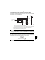
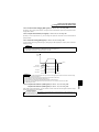
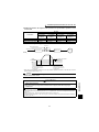
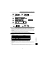
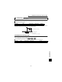
1.4.1
Connecting the control circuit to a power supply separately from the main circuit
If the magnetic contactor (MC) in the inverter power supply is opened when the protective circuit is operated, the
inverter control circuit power is lost and the alarm output signal cannot be kept on. To keep the alarm signal on
terminals R1 and S1 are available. In this case, connect the power supply terminals R1 and S1 of the control circuit
to the primary side of the MC.
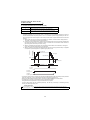
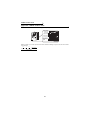
• Model FR-V520-1.5K, 2.2K, FR-V540-1.5K, 2.2K
<Connection procedure>
R
S
T
Terminal block for main circuit
R1
S1
1) Loosen the upper screws
2) Remove the lower screws.
3) Remove the jumpers.
4) Connect the separate power supply cables for control circuit to the
lower terminals (R1, S1). (Note 4)
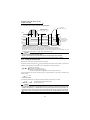
• Model FR-V520-3.7K to 55K, FR-V540-3.7K to 55K
<Connection procedure>
R1 S1
Power supply terminal
block for control circuit
R
S
Power supply terminal
block for control circuit
T
MC
1) Loosen the upper screws.
2) Remove the lower screws.
3) Pull out and remove the jumper.
4) Connect the separate power supply
cables for control circuit to the
upper terminals (R1, S1). (Note 4)
Main power supply
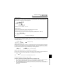
CAUTION
1. When the main circuit power (R, S, T) is on, do not switch off the control power (terminals R1, S1).
Otherwise the inverter may be damaged.
2. When using a separate power supply, the jumpers across R-R1 and S-S1 must be removed. Otherwise
the inverter may be damaged.
3. For a different power supply system, which takes the power of the control circuit from other than the
primary side of the MC, the voltage should be equal to the main circuit voltage.
4. For the FR-V520-3.7K to 55K, FR-V540-3.7K to 55K, the power supply cables must not be connected
to the lower terminals. If connected, the inverter may be damaged.
5. Supplying power to only the R1 and S1 terminals and entering the start signal will result in an error
indication (E.OC1).
10
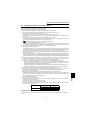
Precautions for use of the vector inverter
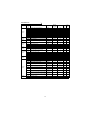
1.5 Precautions for use of the vector inverter
The FR-V500 series is a highly reliable product, but incorrect peripheral circuit making or operation/handling
method may shorten the product life or damage the product.
Before starting operation, always recheck the following items.
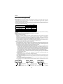
(1) Use insulation-sleeved crimping terminals for the power supply and motor cables.
(2) The inverter will be damaged if power is applied to the inverter output terminals (U, V, W).
(3) After wiring, wire offcuts must not be left in the inverter.
Wire offcuts can cause an alarm, fault or malfunction. Always keep the inverter clean.
When drilling mounting holes in an enclosure etc., take care not to allow chips and other foreign matter to enter
the inverter.
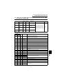
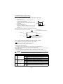
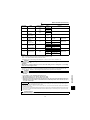
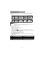
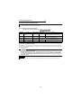
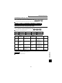
(4) Wire the cables of the recommended size to make a voltage drop 2% or less.
If the wiring distance is long between the inverter and motor, a main circuit cable voltage drop will cause the
motor torque to decrease especially at the output of a high frequency.
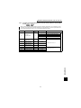
SF-V5RU
SF-V5RUH
3.7kW or less
5.5kW or more
3.7kW or less
5.5kW or more
170V
160V
340V
320V
z Capacity (VA) of separate power supply
The capacity is 60VA or more for 15kW or less and 80VA for 18.5kW to 55kW when separate power is supplied from
R1, S1.
11
1
WIRING
Refer to Instruction Manual (basic) for the recommended wire sizes.
(5) The overall wiring length should be 100m maximum.
Especially for long distance wiring, the fast response current limit function may be reduced or the equipment
connected to the secondary side may malfunction or become faulty under the influence of a charging current
due to the stray capacity of the wiring. Therefore, note the overall wiring length.
(6) Electromagnetic wave interference
The input/output (main circuit) of the inverter includes high frequency components, which may interfere with the
communication devices (such as AM radios) used near the inverter. In this case, install the optional FR-BIF radio
noise filter (for use on the input side only) or FR-BSF01 or FR-BLF line noise filter to minimize interference.
(7) Do not install a power factor correction capacitor, surge suppressor or radio noise filter (FR-BIF option) on the
output side of the inverter.
This will cause the inverter to trip or the capacitor and surge suppressor to be damaged. If any of the above devices is
installed, immediately remove it. (When the FR-BIF radio noise filter is connected, switching power off during motor
operation may result in E. UVT. In this case, connect the radio noise filter in the primary side of the magnetic contactor.)
(8) Before starting wiring or other work after the inverter is operated, wait for at least 10 minutes after the power
supply has been switched off, and check that there are no residual voltage using a tester or the like. The
capacitor is charged with high voltage for some time after power off and it is dangerous.
(9) A short circuit or earth (ground) fault in the inverter output side may damage the inverter modules.
• Fully check the insulation resistance of the circuit prior to inverter operation since repeated short circuits
caused by peripheral circuit inadequacy or an earth (ground) fault caused by wiring inadequacy or reduced
motor insulation resistance may damage the inverter modules.
• Fully check the to-earth (ground) insulation and inter-phase insulation of the inverter secondary side before power on.
Especially for an old motor or use in hostile atmosphere, securely check the motor insulation resistance etc.
(10) Do not use the inverter power supply side magnetic contactor to start/stop the inverter.
Always use the start signal (turn on/off terminals STF, STR-SD) to start/stop the inverter. (Refer to page 14.)
(11) Across the P and PR terminals, connect only an external regenerative brake discharge resistor.
Do not connect a mechanical brake.
(12) Do not apply a voltage higher than the permissible voltage to the inverter I/O signal circuits.
Application of a voltage higher than the permissible voltage to the inverter I/O signal circuits or opposite polarity
may damage the I/O devices. Especially check the wiring to prevent the speed setting potentiometer from
being connected incorrectly to short terminals 10E-5.
(13) Use of single-phase power supply
Do not use single-phase power input.
(14) Precautions for use of any motor other than the vector control dedicated motor (SF-V5RU, SF-VR) and
standard motor with encoder (SF-JR)
a)Vector control cannot be exercised without encoder.
b)Connect the encoder to the backlash-free motor shaft.
(15) Since the rated voltage differs from the commercial power supply voltage, the Mitsubishi dedicated motor
cannot perform bypass operation.
Others
1.6 Others
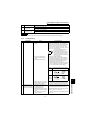
1.6.1
Leakage currents and countermeasures
Leakage currents flow through static capacitances existing in the inverter I/O wiring and motor. Since their values
depend on the static capacitances, carrier frequency, etc., take the following measures.
(1)
To-earth (ground) leakage currents
Leakage currents may flow not only into the inverter's own line but also into the other lines through the earth
(ground) cable, etc.
These leakage currents may operate earth (ground) leakage breakers and earth (ground) leakage relays
unnecessarily.
z Countermeasures
• When the carrier frequency setting is high, decrease the carrier frequency (Pr. 72) of the inverter.
Note that motor noise increases. Selection of Soft-PWM (Pr. 240) will make it unoffending.
• By using earth (ground) leakage circuit breakers designed for harmonic and surge suppression in the inverter's
own line and other line, operation can be performed with the carrier frequency kept high (with low noise).
(2) Line-to-line leakage currents
Harmonics of leakage currents flowing in static capacitances between the inverter output cables may operate the
external thermal relay unnecessarily. When the wiring length is long (50m or more) for the 400V class smallcapacity model (7.5kW or less), the external thermal relay is likely to operate unnecessarily because the ratio of the
leakage current to the rated motor current increases.
z Line-to-line leakage current data example (200V class)
Motor Capacity
(kW)
Rated Motor
Current(A)
1.5
2.2
9.0
13.0
Leakage Current (mA)
Wiring length 50m
Wiring length100m
370
400
560
590
•
•
•
•
Motor SF-V5RU 4P
Carrier frequency: 13.5KHz
Cable :2mm24-core
Cab tyre cable
*The leakage currents of the 400V class are about twice larger.
MCCB
Power supply
Thermal relay
Motor
Inverter
IM
Line static capacitances
Line-to-Line Leakage Current Path
z Measures
• Use the electronic thermal relay function (Pr. 9) of the inverter.
• Decrease the carrier frequency. Note that motor noise increases. Selection of Soft-PWM (Pr. 240) will make it
unoffending.
For other than the dedicated motor (SF-V5RU), using a temperature sensor to directly detect the motor
temperature is recommended to ensure that the motor is protected against line-to-line leakage currents.
z Installation and selection of moulded case circuit breaker
Install a moulded case circuit breaker (MCCB) on the power receiving side to protect the wiring of the inverter
primary side. Select the MCCB according to the power supply side power factor (which depends on the power
supply voltage, output frequency and load). Especially for a completely electromagnetic MCCB, one of a slightly
large capacity must be selected since its operation characteristic varies with harmonic currents. (Check it in the
data of the corresponding breaker.) As an earth (ground) leakage breaker, use the Mitsubishi earth (ground)
leakage breaker designed for harmonics and surges.
12
Others
(3) Selection of rated sensitivity current of earth (ground) leakage breaker
Leakage current (mA)
Leakage current (mA)
When using the earth (ground) leakage breaker with the inverter circuit, select its rated sensitivity current as follows,
independently of the PWM carrier frequency.
• Breaker designed for harmonic and surge
Leakage Current Example of Cable
Leakage Current Example of
Rated sensitivity current
Path per 1km during Commercial
three-Phase Induction Motor during
IΔn ≥10 × (Ig1 + lgn + Ig2 + Igm)
Power Supply Operation When CV
Commercial Power Supply Operation
• Standard breaker
Cable Is Routed in Metal Conduit
(200V 60Hz)
(200V 60Hz)
Rated sensitivity current
2.0
120
IΔn ≥10 × {Ig1 + Ign + 3 × (Ig2 + Igm)}
100
Ig1, Ig2: Leakage currents of cable path
1.0
during commercial power supply operation
80
0.7
0.5
Ign *: Leakage current of noise filter on
60
0.3
inverter input side
40
0.2
Igm: Leakage current of motor during
20
commercial power supply operation
0
0.1
2 3.5
8 14 22 38 80 150
5.5
30 60 100
1.5 3.7 7.5 15 22 37 55
2.2 5.5 11 18.5 3045
Cable size (mm2)
Motor capacity (kW)
<Example>
2mm2
2mm2
5m
70m
Noise
filter
NV
3φ
IM 200V1.5kW
Inverter
Ig1
Ign
Ig2
Igm
CAUTION
• Install the NV on the primary (power supply) side of the inverter.
• In the
connection neutral point earthing (grounding) system, the sensitivity current is purified
against an earth (ground) fault in the inverter secondary side. Earthing (Grounding) must conform to
the requirements of national and local safety regulations and electrical codes. (NEC section 250, IEC
536 class 1 and other applicable standards)
• When the breaker is installed on the secondary side of the inverter, it may be unnecessarily operated
by harmonics even if the effective value is less than the rating.
In this case, do not install the breaker since the eddy current and hysteresis loss will increase, leading
to temperature rise.
• The following models are standard breakers:
BV-C1, BC-V, NVB, NV-L, NV-G2N, NV-G3NA, and NV-2F type leakage current relays (except for NVZHA), NV with AA neutral wire open phase protection
The following models are breakers for harmonic and surge suppression:
NV-C/NV-S/MN series, NV30-FA, NV50-FA, BV-C2, leakage current alarm breaker (NF-Z), NV-ZHA, NV-H
* Note the leakage current value of the noise filter installed on the inverter input side.
Breaker Designed for Harmonic and
Surge
20 ×
Leakage current Ign (mA)
Leakage current Ig2 (mA)
Motor leakage current Igm
(mA)
Total leakage current (mA)
Rated sensitivity current
(mA) ( ≥Ig × 10)
WIRING
5m
= 0.10
1000m
0 (without noise filter)
70m
20 ×
= 1.40
1000m
Leakage current Ig1 (mA)
0.14
1.66
4.78
30
100
13
1
Standard Breaker
Others
1.6.2
Power off and magnetic contactor (MC)
(1) Inverter primary side magnetic contactor (MC)
On the inverter primary side, it is recommended to provide an MC for the following purposes.
(
Refer to the Instruction Manual (basic) for selection.)
1)
2)
3)
4)
To release the inverter from the power supply when the inverter protective function is activated or the drive
becomes faulty (e.g. emergency stop operation)
When cycle operation or heavy-duty operation is performed with an optional brake resistor connected,
overheat and burnout of the discharging resistor can be prevented if a regenerative brake transistor is
damaged due to insufficient heat capacity of the discharging resistor and excess regenerative brake duty.
To prevent any accident due to an automatic restart at restoration of power after an inverter stop made by a
power failure
To rest the inverter for an extended period of time
The control power supply for inverter is always running and consumes a little power. When stopping the
inverter for an extended period of time, powering off the inverter will save power slightly.
To separate the inverter from the power supply to ensure safe maintenance and inspection work
Since the MC on the inverter input side is used for the above purposes, they correspond to the standard duties.
Therefore, when making an emergency stop during running, select a JEM1038 class AC3 MC for the inverter
input side currents.
REMARKS
The MC may be switched on/off to start/stop the inverter. However, since repeated inrush currents at power on will shorten the
life of the converter circuit (switching life is about 100,000 times), frequent starts and stops must be avoided. Turn on/off the
inverter start controlling terminals (STF, STR) to run/stop the inverter.
.
z Inverter start/stop circuit example
MCCB
As shown on the right, always use the start
signal (turn on/off terminals STF, STR-SD) to
start/stop the inverter.
(Refer to page 26.)
MC
U
R
Power
supply
S
V
T
W
To motor
R1
*2
S1
T *1
Inverter
Operation ready
OFF
A
ON
B
MC
MC
C
RA
STF(STR)
SD
Start/Stop
Operation
MC
RA
OFF
RA
REMARKS
*1. When the power supply is 400V class, install a step-down transformer.
*2. Connect the power supply terminals R1, S1 to the primary side of the MC to hold an alarm signal when the inverter's
protective circuit is activated. At this time, remove jumpers across terminals R-R1 and S-S1. (Refer to page 10 for
removal of jumpers)
(2) Handling of secondary side magnetic contactor
In principle, do not provide a magnetic contactor between the inverter and motor and switch it from off to on during
operation. If it is switched on during inverter operation, a large inrush current may flow, stopping the inverter due to
overcurrent shut-off. When an MC is provided for switching to the commercial power supply, for example, switch it
on/off after the inverter and motor have stopped.
14
Others
1.6.3
Installation of reactor
When the inverter is connected near a large-capacity power transformer (1000kVA or more and wiring length 10m
max.) or when a power capacitor is to be switched over, an excessive peak current may flow in the power input
circuit, damaging the converter circuit. To prevent this, always install the DC reactor or AC reactor (FR-HEL/BEL or
FR-HAL/BAL).
Power
supply
MC
AC reactor
(FR-HAL/BAL) Inverter
R
X
S
Y
T
Z
R
U
S
V
T
P
W
P1
IM
Power supply
equipment capacity
(kVA)
MCCB
1500
Reactor
installation
range
1000
0
10 Wiring length (m)
DC reactor
(FR-HEL/BEL) *
REMARKS
* When connecting the FR-HEL/BEL, remove the jumper across terminals P-P1.
The wiring length between the FR-HEL/BEL and inverter should be 5m maximum and minimized.
Use the same wire size as that of the power supply wire (R, S, T). (
Refer to the Instruction Manual (basic).)
WIRING
1
15
Others
1.6.4
Notes on earthing (grounding)
z Use the dedicated earth (ground) terminal to earth (ground) the inverter. (Do not use the screw in the case,
chassis, etc.)
Use a tinned crimping terminal which does not contain zinc to connect the earth (ground) cable. Tighten the
screw, taking care not to break its threads.
z Use the largest possible gauge for the earth (ground) cable. The gauge should be equal to or larger than those
indicated in the following table. The earthing (grounding) point should be as near as possible to the inverter to
minimize the earth (ground) cable length.
(Unit: mm2)
Motor Capacity
2.2kW or less
3.7kW
5.5kW, 7.5kW
11kW, 15kW
18.5kW to 37kW
45kW, 55kW
Earth (Ground) Cable Gauge
200V
400V
2 (2.5)
3.5 (4)
5.5 (6)
14 (16)
22 (25)
38 (35)
2 (2.5)
2 (2.5)
3.5 (4)
8 (10)
14 (16)
22 (25)
For use as a Low Voltage Directive-compliant product, use the PVC cables indicated in the parentheses for earthing
(grounding).
z Earth (Ground) the motor on the inverter side using one wire of the 4-core cable.
z Always earth (ground) the motor and inverter.
(1)Purpose of earthing (grounding)
Generally, an electrical apparatus has an earth (ground) terminal, which must be connected to the ground
before use.
An electrical circuit is usually insulated by an insulating material and encased. However, it is impossible to
manufacture an insulating material that can shut off a leakage current completely, and actually, a slight current
flow into the case. The purpose of earthing (grounding) the case of an electrical apparatus is to prevent
operator from getting an electric shock from this leakage current when touching it.
To avoid the influence of external noises, this earthing (grounding) is important to audio equipment, sensors,
computers and other apparatuses that handle low-level signals or operate very fast.
(2)Earthing (Grounding) methods and earthing (grounding) work
As described previously, earthing (grounding) is roughly classified into an electrical shock prevention type and
a noise-affected malfunction prevention type. Therefore, these two types should be discriminated clearly, and
the following work must be done to prevent the leakage current having the inverter's high frequency
components from entering the malfunction prevention type earthing (grounding):
(a) Where possible, use independent earthing (grounding) for the inverter.
If independent earthing (grounding) (I) is impossible, use joint earthing (grounding) (II) where the inverter is
connected with the other equipment at an earthing (grounding) point. Joint earthing (grounding) as in (III)
must be avoided as the inverter is connected with the other equipment by a common earth (ground) cable.
Also a leakage current including many high frequency components flows in the earth (ground) cables of the
inverter and inverter-driven motor. Therefore, they must use the independent earthing (grounding) method
and be separated from the earthing (grounding) of equipment sensitive to the aforementioned noises.
In a tall building, it will be a good policy to use the noise malfunction prevention type earthing (grounding)
with steel frames and carry out electric shock prevention type earthing (grounding) in the independent
earthing (grounding) method.
(b) Earthing (Grounding) must conform to the requirements of national and local safety regulations and
electrical codes.
(NEC section 250, IEC 536 class 1 and other applicable standards).
(c) Use the thickest possible earth (ground) cable. The earth (ground) cable should be of not less than the size
indicated in the above table.
(d) The earthing (grounding) point should be as near as possible to the inverter to minimize the earth (ground)
cable length.
(e) Run the earth (ground) cable as far away as possible from the I/O wiring of equipment sensitive to noises
and run them in parallel in the minimum distance.
(f) Use one wire in a 4-core cable with the earth (ground) terminal of the motor and earth (ground) it on the
inverter side.
Inverter
Other
equipment
200V class
class D earthing (grounding)
400V class
class C earthing (grounding)
(I) Independent earthing (grounding) ... Best
Inverter
Other
equipment
200V class
class D earthing (grounding)
400V class
class C earthing (grounding)
(II) Joint earthing (grounding) ... Good
16
Inverter
Other
equipment
200V class
class D earthing (grounding)
400V class
class C earthing (grounding)
(III) Joint earthing (grounding) ... Not allowed
Others
1.6.5
Inverter-generated noises and their reduction techniques
Some noises enter the inverter to malfunction it and others are radiated by the inverter to malfunction peripheral
devices. Though the inverter is designed to be insusceptible to noises, it handles low-level signals, so it requires the
following basic techniques. Also, since the inverter chops outputs at high carrier frequency, that could generate
noises. If these noises cause peripheral devices to malfunction, measures should be taken to suppress noises.
These techniques differ slightly depending on noise propagation paths.
2)
3)
Basic techniques
• Do not run the power cables (I/O cables) and signal cables of the inverter in parallel with each other and do
not bundle them.
• Use twisted pair shielded cables for the detector connection and control signal cables, and connect the
sheathes of the shield cables to terminal SD.
• Earth (Ground) the inverter, motor, etc. at one point.
Techniques to reduce noises that enter and malfunction the inverter
When devices that generate many noises (which use magnetic contactors, magnetic brakes, many relays, for
example) are installed near the inverter and the inverter may be malfunctioned by noises, the following
measures must be taken:
•Provide surge suppressors for devices that generate many noises to suppress noises.
•Fit data line filters (page 18) to signal cables.
•Earth (Ground) the shields of the detector connection and control signal cables with cable clamp metal.
Techniques to reduce noises that are radiated by the inverter to malfunction peripheral devices
Inverter-generated noises are largely classified into those radiated by the cables connected to the inverter and
inverter main circuits (I/O), those electromagnetically and electrostatically induced to the signal cables of the
peripheral devices close to the main circuit power supply, and those transmitted through the power supply
cables.
Invertergenerated
noise
Air-propagated
noises
Noises directly
radiated by inverter
Path 1
Noises radiated
by power cables
Path 2
Noises radiated
by motor cables
Path 3
Magnetic
induction noises
Path 4, 5
Static induction
noises
Path 6
Cable-propagated noises
Noises propagated
through power cables
Noise from earth
(Ground) cable due to
leakage current
5)
7)
Telephone
7)
2)
1)
Instrument
Receiver
Sensor
power supply
3) Inverter
4)
Path 7
Motor IM
6)
1)
8)
3) Sensor
Path 8
• By decreasing the carrier frequency, the mains terminal interface voltage* can be reduced. When motor noise
does not pose a problem, set the carrier frequency to a low value using Pr. 72.
(*Mains terminal interface voltage represents the magnitude of noise propagated from the inverter to the power
supply side.)
• Using shield cables as signal cables, induction noise can be reduced greatly (to 1/10 - 1/100). Induction noise
can also be reduced by separating the signal cables from the inverter output cables. (Separation of 30cm
reduces noise to 1/2-1/3.)
By fitting the FR-BSF01 or BLF on the inverter output side, induction noise to the signal cables can be reduced.
17
1
WIRING
1)
Others
Noise Propagation
Path
Measures
When devices that handle low-level signals and are liable to malfunction due to noises, e.g.
instruments, receivers and sensors, are contained in the enclosure that contains the inverter or when
their signal cables are run near the inverter, the devices may be malfunctioned by air-propagated
noises. The following measures must be taken:
(1) Install easily affected devices as far away as possible from the inverter.
(2) Run easily affected signal cables as far away as possible from the inverter and its I/O cables.
(3) Do not run the signal cables and power cables (inverter I/O cables) in parallel with each other and
do not bundle them.
(4) Insert line noise filters into I/O and radio noise filters into input to suppress cable-radiated noises.
(5) Use shielded cables as signal cables and power cables and run them in individual metal conduits
to produce further effects.
When the signal cables are run in parallel with or bundled with the power cables, magnetic and static
induction noises may be propagated to the signal cables to malfunction the devices and the following
measures must be taken:
(1) Install easily affected devices as far away as possible from the inverter.
(2) Run easily affected signal cables as far away as possible from the I/O cables of the inverter.
(3) Do not run the signal cables and power cables (inverter I/O cables) in parallel with each other and
do not bundle them.
(4) Use shielded cables as signal cables and power cables and run them in individual metal conduits
to produce further effects.
When the power supplies of the peripheral devices are connected to the power supply of the inverter in
the same line, inverter-generated noises may flow back through the power supply cables to
malfunction the devices and the following measures must be taken:
(1) Install the radio noise filter (FR-BIF) to the power cables (input cables) of the inverter.
(2) Install the line noise filter (FR-BLF, FR-BSF01) to the power cables (I/O cables) of the inverter.
When a closed loop circuit is formed by connecting the peripheral device wiring to the inverter, leakage
currents may flow through the earth (ground) cable of the inverter to malfunction the device. In such a
case, disconnection of the earth (ground) cable of the device may cause the device to operate properly.
1), 2), 3)
4), 5), 6)
7)
8)
z Data line filters
Noise entry can be prevented by providing a data line filter for the detector cable etc.
z Example of noise reduction techniques
Install filter
(FR-BLF, FR-BSF01)
on inverter input side.
Reduce carrier
Control box frequency.
Inverter
power supply
Install FR-BIF filter
on inverter input side.
Separate inverter and power
line by more than 30cm
(at least 10cm) from sensor circuit.
Control
power supply
Do not earth (ground)
control box directly.
FRBLF
Inverter
Install filter
(FR-BLF, FR-BSF01)
on inverter output side.
FRBLF
IM Motor
Use 4-core cable as motor
power cable and use one wire
as earth (ground) wire.
FRBIF
Use twisted pair shield cable.
Sensor
Power supply
for sensor
Do not earth (ground) shield but connect
it to common cable of signal.
Do not earth (ground)
control cable.
18
Others
1.6.6
Power supply harmonics
Power supply harmonics may be generated from the converter section of the inverter, affecting the power supply
equipment, power capacitors, etc. Power supply harmonics are different in generation source, frequency and
transmission path from radio frequency (RF) noise and leakage currents. Take the following measures.
z The differences between harmonics and RF noises are indicated below:
Item
Frequency
Environment
Quantitative understanding
Generated amount
Immunity of affected device
Examples of safeguard
Harmonics
RF Noise
Normally 40 to 50th degrees (3kHz or less) High frequency (several 10kHz to 1GHz order)
To wire paths, power impedance
Across spaces, distance, laying paths
Occurs randomly, quantitative understanding is
Logical computation is possible
difficult.
Approximately proportional to load
According to current fluctuation rate (larger with
capacity
faster switching)
Specified in standards for each device.
Differs according to maker's device specifications.
Install a reactor.
Increase the distance.
z Safeguard
The harmonic current generated from the inverter
to the power supply differs according to various
conditions such as the wiring impedance, whether
a reactor is used or not, and output frequency and
output current on the load side.
For the output frequency and output current, the
adequate method is to obtain them under rated
load at the maximum operating frequency.
DC reactor
Inverter
MCCB
AC reactor
IM
Motor
Do not insert power factor
improving capacitor.
CAUTION
The power factor improving capacitor and surge suppressor on the inverter output side may be
overheated or damaged by the high frequency components of the inverter output. Also, since an
excessive current flows in the inverter to activate overcurrent protection, do not provide a capacitor and
surge suppressor on the inverter output side when the motor is driven by the inverter. To improve the
power factor, insert a reactor on the inverter's primary side or in the DC circuit.
WIRING
1
19
Others
1.6.7
Harmonic suppression guidelines
Harmonic currents flow from the inverter to a power receiving point via a power transformer. The harmonic
suppression guidelines were established to protect other consumers from these outgoing harmonic currents.
The three-phase 200V input specifications 3.7kW or less are previously covered by "Harmonic suppression
guideline for household appliances and general-purpose products" and other models are covered by "Harmonic
suppression guideline for consumers who receive high voltage or special high voltage". However, the generalpurpose inverter has been excluded from the target products covered by "Harmonic suppression guideline for
household appliances and general-purpose products" in January 2004. Later, this guideline was repealed on
September 6, 2004. All capacities of all models are now target products of "Harmonic suppression guideline for
consumers who receive high voltage or special high voltage" (hereinafter referred to as "guideline for specific
consumers").
"Guideline for specific consumers"
This guideline sets forth the maximum values of harmonic currents outgoing from a high-voltage or especially
high-voltage consumer who will install, add or renew harmonic generating equipment. If any of the maximum
values is exceeded, this guideline requires that consumer to take certain suppression measures.
Table 1 Maximum Values of Outgoing Harmonic Currents per 1kW Contract Power
Received
Power Voltage
5th
7th
11th
13th
17th
19th
23rd
Over 23rd
6.6kV
22kV
33kV
3.5
1.8
1.2
2.5
1.3
0.86
1.6
0.82
0.55
1.3
0.69
0.46
1.0
0.53
0.35
0.9
0.47
0.32
0.76
0.39
0.26
0.70
0.36
0.24
(1) Application of the guideline for specific consumers
New installation/addition/
renewal of equipment
Calculation of equivalent
capacity sum
Not more than
reference capacity
Sum of
equivalent capacities
Over reference capacity
Calculation of outgoing
harmonic current
Is outgoing
harmonic current equal to
or lower than maximum
value?
Over maximum value
Not more than
maximum value
Harmonic suppression
technique is not required.
Harmonic suppression
technique is not required.
Table 2 Conversion Factors for FR-V500 Series
Class
Circuit Type
3
Three-phase bridge
(Capacitor-smoothed)
Without reactor
With reactor (AC side)
With reactor (DC side)
With reactors (AC, DC sides)
5
Self-excitation three-phase
bridge
When high power factor converter is used
Table 3 Equivalent Capacity Limits
Received Power Voltage
Reference Capacity
6.6kV
22/33kV
66kV or more
50kVA
300kVA
2000kVA
20
Conversion Factor Ki
K31 = 3.4
K32 = 1.8
K33 = 1.8
K34 = 1.4
K5 = 0
Others
Table 4 Harmonic Content (Values of the fundamental current is 100%.)
Reactor
Not used
Used (AC side)
Used (DC side)
Used (AC, DC sides)
1)
5th
7th
11th
13th
17th
19th
23rd
25th
65
38
30
28
41
14.5
13
9.1
8.5
7.4
8.4
7.2
7.7
3.4
5.0
4.1
4.3
3.2
4.7
3.2
3.1
1.9
3.2
2.4
2.6
1.7
3.0
1.6
1.8
1.3
2.2
1.4
Calculation of equivalent capacity P0 of harmonic generating equipment
The "equivalent capacity" is the capacity of a 6-pulse converter converted from the capacity of consumer's
harmonic generating equipment and is calculated with the following equation. If the sum of equivalent
capacities is higher than the limit in Table 3, harmonics must be calculated with the following procedure:
P0 = Σ Ki × Pi [kVA]
* Rated capacity: Determined by the capacity of the applied
Ki : Conversion factor (refer to Table 2)
motor and found in Table 5. It should be noted that the
rated capacity used here is used to calculate generated
Pi : Rated capacity of harmonic generating
harmonic amount and is different from the power supply
equipment* [kVA]
capacity required for actual inverter drive.
i : Number indicating the conversion circuit type
2)
Calculation of outgoing harmonic current
Outgoing harmonic current = fundamental wave current (value converted from received power voltage)
× operation ratio × harmonic content
• Operation ratio: Operation ratio = actual load factor × operation time ratio during 30 minutes
• Harmonic contents: Found in Table 4
Table 5 Rated Capacities and Outgoing Harmonic Currents for Inverter Drive
200V
400V
1.5
2.2
3.7
5.5
7.5
11
15
18.5
22
30
37
45
55
5.50
7.93
13.0
19.1
25.6
36.9
49.8
61.4
73.1
98.0
121
147
180
2.75
3.96
6.50
9.55
12.8
18.5
24.9
30.7
36.6
49.0
60.4
73.5
89.9
3)
Fundamen
tal Wave
Rated
Current
Capacity
Converted
from 6.6kV (kVA)
(mA)
167
240
394
579
776
1121
1509
1860
2220
2970
3660
4450
5450
1.95
2.81
4.61
6.77
9.07
13.1
17.6
21.8
25.9
34.7
42.8
52.1
63.7
Outgoing Harmonic Current Converted from 6.6kV (mA)
(No reactor, 100% operation ratio)
5th
7th
11th
13th
17th
19th
23rd
25th
108.6
156.0
257.1
376.1
504.4
728.7
980.9
1209
1443
1931
2379
2893
3543
68.47
98.40
161.5
237.4
318.2
459.6
618.7
762.6
910.2
1218
1501
1825
2235
14.20
20.40
33.49
49.22
65.96
95.29
128.3
158.1
188.7
252.5
311.1
378.3
463.3
12.86
18.48
30.34
44.58
59.75
86.32
116.2
143.2
170.9
228.7
281.8
342.7
419.7
7.181
10.32
16.94
24.90
33.37
48.20
64.89
79.98
95.46
127.7
157.4
191.4
234.4
5.177
7.440
12.21
17.95
24.06
34.75
46.78
57.66
68.82
92.07
113.5
138.0
169.0
4.342
6.240
10.24
15.05
20.18
29.15
39.24
48.36
57.72
77.22
95.16
115.7
141.7
3.006
4.320
7.092
10.42
13.97
20.18
27.16
33.48
39.96
53.46
65.88
80.10
98.10
Harmonic suppression technique requirement
If the outgoing harmonic current is higher than the maximum value per 1kW contract power × contract power, a
harmonic suppression technique is required.
21
1
WIRING
Rated Current
[A]
Applied
Motor
kW
Others
4)
Harmonic suppression techniques
No.
1
2
3
Item
Reactor installation
(ACL, DCL)
High power factor
converter
(FR-HC)
Installation of power
factor improving capacitor
4
Transformer multi-phase
operation
5
Passive filter
(AC filter)
6
Active filter
1.6.8
Description
Install a reactor (ACL) on the AC side of the inverter or a reactor (DCL) on its DC side or
both to suppress outgoing harmonic currents.
The converter circuit is switched on-off to convert an input current waveform into a sine
wave, suppressing harmonic currents substantially. The high power factor converter (FRHC) is used with the standard accessory.
When used with a series reactor, the power factor improving capacitor has an effect of
absorbing harmonic currents.
Use two transformers with a phase angle difference of 30° as in -delta, delta-delta
combination to provide an effect corresponding to 12 pulses, reducing low-degree
harmonic currents.
A capacitor and a reactor are used together to reduce impedance at specific frequencies,
producing a great effect of absorbing harmonic currents.
This filter detects the current of a circuit generating a harmonic current and generates a
harmonic current equivalent to a difference between that current and a fundamental wave
current to suppress a harmonic current at a detection point, providing a great effect of
absorbing harmonic currents.
Inverter-driven 400V class motor
In the PWM type inverter, a surge voltage attributable to wiring constants is generated at the motor terminals.
Especially for a 400V class motor, the surge voltage may deteriorate the insulation. When the 400V class motor is
driven by the inverter, consider the following measures:
z Measures
It is recommended to take either of the following measures.
(1) Rectifying the motor insulation
For the 400V class motor, use an insulation-enhanced motor. Specifically,
1) Specify the "400V class inverter-driven, insulation-enhanced motor".
2) For the dedicated motor such as the constant-torque motor or low-vibration motor, use the "inverter-driven,
dedicated motor".
CAUTION
• If the wiring length between the motor and inverter is 40m or longer, set Pr. 240 to long wiring mode in
addition to the above countermeasures to operate the inverter. (Refer to page 112 for Pr. 240 "SoftPWM selection".)
22
Others
1.6.9
Using the PU connector for computer link
(1) When connecting the control panel or parameter unit using a connection cable
Refer to the Instruction Manual (basic).
(2) For RS-485 communication
The PU connector can be used to perform communication operation from a personal computer etc.
When the PU connector is connected with a personal, FA or other computer by a communication cable, a user
program can run and monitor the inverter or read and write to parameters.
<PU connector pin-outs>
Viewed from the inverter (receptacle side) front
8)
1) SG
2) P5S
3) RDA
4) SDB
1)
5) SDA
6) RDB
7) SG
8) P5S
CAUTION
1. Do not connect the PU connector to the computer's LAN board, FAX modem socket or telephone
modular connector. Otherwise, the product may be damaged due to electrical specification
differences.
2. Pins No. 2 and 8 (P5S) provide power to the control panel or parameter unit.
Do not use these pins for RS-485 communication.
<System configuration example>
(1) Connection of a computer to the inverter (1:1 connection)
Computer
Station 0
Computer
Inverter
RS-232C
connector
RS-485
connector
RS-485
Interfase
terminal
RS-232C
cable
RJ-45
connector 2)
10BASE-T cable 1)
Station 0
Inverter
Maximum 15m
RS-485
connector
RS-232C RS-485
converter
RJ-45 connector 2)
10BASE-T cable 1)
zComputer - inverter connection cable
Type
Maker
FA-T-RS40 type*
Mitsubishi Electric Engineering Co., Ltd
* The converter cable cannot connect two or more inverters (the computer and inverter are connected on a 1:1
basis). Since the product is packed with the RS-232C cable and RS-485 cable (10BASE-T + RJ-45 connector),
the cable and connector need not be prepared separately. Contact a maker for details of the product.
REMARKS
When fabricating the cable on the user side, see below.
Examples of commercially available products (as of September, '06)
Product
1)
10BASE-T cable
2)
RJ-45 connector
Type
Maker
SGLPEV-T 0.5mm × 4P
Mitsubishi Cable Industries, Ltd.
* Do not use No. 2 and No. 8 pin (P5S).
5-554720-3
Tyco Electronics Corporation
23
1
WIRING
For a connection cable between the computer having RS-232C and the inverter (RS-232C⇔RS-485
converter), refer to the table below.
Examples of commercially available products (as of September, '06)
Others
(2) Connection of a computer to multiple inverters (1:n connection)
Computer
RS-485
interface
terminal
Station 1
Station 2
Inverter
Inverter
Station n (up to 32)
Inverter
RS-485
connector
RS-485
connector
RS-485
connector
Distributor
RJ-45 connector 2)
10BASE-T cable 1)
RS-232C
cable
Terminating
resistor
Computer
Station 1
Station 2
Station n
RS-232C
connector
Inverter
Inverter
Inverter
RS-485
connector
RS-485
connector
RS-485
connector
Maximum
15m
Converter
Distributor
Terminating
resistor
10BASE-T cable 1)
RJ-45 connector 2)
REMARKS
When fabricating the cable on the user side, see below.
Examples of commercially available products (as of September, '06)
Product
1)
2)
10BASE-T cable
RJ-45 connector
Type
Maker
SGLPEV-T 0.5mm × 4P *
5-554720-3
* Do not use No. 2 and No. 8 pin (P5S) of the 10 BASE-T cable.
24
Mitsubishi Cable Industries, Ltd.
Tyco Electronics Corporation
Others
<Wiring method>
1)
Wiring of one RS-485 computer and one inverter
Cable connection and signal direction
Computer Side Terminals
Signal name
2)
Description
Inverter
PU connector
10 BASE-T cable
RDA
Receive data
RDB
Receive data
SDB
SDA
Send data
RDA
SDB
Send data
RDB
RSA
Request to send
RSB
Request to send
CSA
Clear to send
CSB
Clear to send
SDA
(Caution 1)
0.2mm2 or more
SG
Signal ground
FG
Frame ground
SG
Wiring of one RS-485 computer and "n" (multiple) inverters
Cable connection and signal direction
Computer
10 BASE-T cable
RDA
RDB
Terminating
resistor
(Caution 2)
SDA
SDB
SDA
SDB
RDA
RDB
SDA
SDB
RDA
RDB
SDA
SDB
(Caution 1)
CSA
RDA
RSB
RDB
RSA
CSB
SG
FG
SG
SG
SG
Station 1
Station 2
Station n
Inverter
Inverter
Inverter
CAUTION
1. Make connections in accordance with the manual of the computer used.
Fully check the terminal numbers of the computer since they vary with the model.
2. There may be the influence of reflection depending on the transmission speed and/or transmission
distance. If this reflection hinders communication, provide a terminating resistor. If the PU connector
is used to make a connection, use a distributor since a terminating resistor cannot be fitted.
Connect the terminating resistor to only the inverter remotest from the computer.
(terminating resistor: 100Ω)
WIRING
1
25
Input terminals
1.7 Input terminals
1.7.1
Run (start) and stop (STF, STR, STOP)
To start and stop the motor, first switch on the input power of the inverter (when there is a magnetic contactor on the
input side, use the operation-ready switch to turn on the magnetic contactor), then start the motor with the forward
or reverse rotation start signal.
Two-wire type (STF, STR)
MCCB
A two-wire type connection is shown on the right.
1) The forward/reverse rotation signal is used as both
the start and stop signals. Turn on either of the
forward and reverse rotation signals to start the
motor in the corresponding direction. Turn on both or
turn off the start signal during operation to decelerate
the inverter to a stop.
2) The speed setting signal may either be given by
entering 0 to 10VDC across the speed setting input
terminal 2-5 or by setting the required values in Pr. 4
to Pr. 6 "three-speed setting" (high, middle, low
speeds). (Refer to page 77 for three-speed
operation.)
Power
supply
R, S, T
Inverter
Forward
rotation start
Reverse
rotation start
STF
STR (Pr.187 = "9999")
SD
Output speed
(1)
Time
ON
Across STF-SD
(STR)
Two-Wire Type Connection Example
(2)
Three-wire type (STF, STR, STOP)
A three-wire type connection is shown on the right. Assign
the start self-holding signal (STOP) to any of the input
terminals.
1) Short signals STOP-SD to enable the start self-holding
function. In this case, the forward/reverse rotation
signal functions only as a start signal.
MCCB
Power
supply
Stop
Forward rotation
start
STF
Reverse rotation
start
4)
5)
STOP (Set "25" in any of
Pr. 180 to Pr. 183)
If the start signal terminals STF (STR)-SD are once
shorted, then opened, the start signal is kept on and
starts the inverter. To change the rotation direction,
short the start signal STR (STF)-SD once, then open it.
The inverter is decelerated to a stop by opening
terminals STOP-SD once. The three-wire connection
is shown on the right.
When terminals JOG-SD are shorted, the STOP signal
is invalid and jog signal has precedence.
If the output stop terminals MRS-SD are shorted, the
self-holding function is not deactivated.
26
Output speed
Assign the STOP signal to any of Pr. 180 to Pr. 183 and
Pr. 187 (input terminal function selection).
3)
STR (Pr.187 = "9999")
SD
REMARKS
2)
R, S, T
Inverter
Time
ON
Start
ON
Stop
Three-Wire Type Connection Example
Input terminals
1.7.2
External thermal relay input (OH)
When the external thermal relay or the built-in thermal relay of the motor (thermal
relay protector) is actuated to protect the motor from overheat, the inverter output
can be shut off and the corresponding alarm signal can be provided to hold a stop
status. Even if the thermal relay contact resets, the motor cannot be restarted unless
the reset terminal RES-SD are shorted for more than 0.1s and then opened or a
power-on reset is made.
Therefore, this function can be used as an externals emergency stop signal input.
1.7.3
Inverter
U
V
W
OH
SD
Thermal relay
Motor
IM
Speed setting potentiometer connection (10E, 2 (1), 5)
As an analog speed setting input signal, a voltage signal can be input.
The relationships between the speed setting input voltages and output speeds are as shown below. The speed
setting input signals are proportional to the output speeds. Note that when the input signal is less than the starting
speed, the output speed of the inverter is 0r/min.
If the input signal of 10VDC or higher is entered, it cannot exceed Pr. 1 "maximum speed".
Output speeds (r/min)
Speed setting terminal 2 gain speed
(Terminal 1 gain)
(30r/min to 3600r/min)
Maximum speed
(0 to 3600r/min)
Minimum speed
(0 to 3600r/min)
Input voltage is
proportional to
output speed.
Pr.1
Starting speed
(0 to 1500r/min)
1
0
Pr.903
Pr.918
Pr.2
Pr.13
Speed setting signals
10V Pr.73
Relationships between Speed Setting Inputs and Output Speeds
Related parameters
Maximum speed setting Pr. 1 "maximum speed" (Refer to page 76.)
(1) Voltage input (10E, 2, 5)
Enter the speed setting input signal of 0 to 10VDC across the speed setting input terminals 2-5. The maximum
output speed is reached when 10V is input across terminals 2-5.
The power supply used may either be the inverter's built-in power supply or an external power supply. For the builtin power supply, terminals 10E-5 provide 10VDC output.
• Use terminal 10E for the built-in power supply.
0 to 10VDC
10E
WIRING
+10V
1
2
5
(2) Multi-function input (1, 5)
The analog input function can be multi-functioned, e.g. compensation signal may be entered across the main speed
setting terminals 2-5 for synchronous operation.
Across auxiliary input terminals 1-5 ... 0 to ±10VDC
The function of terminal 1 depends on the setting of Pr. 868 "terminal 1 function assignment". Refer to page 183 for
details of Pr. 868.
27
Input terminals
1.7.4
Torque setting input signal and motor-generated torque (terminals 3, 5)
Refer to the diagrams shown at below right for the relationship between the torque setting input signal and output
voltage. The torque setting input signal is in proportion to the output torque. However, motor-generated torque
varies with the motor temperature. The guideline of the output torque accuracy relative to the torque setting input is
torque accuracy ±3% (under condition of 75°C) when the SF-V5RU vector control inverter motor is used.
Gain Pr. 905
Output torque
(Torque command)
150%
3
0 to ±10VDC
5
Common(-)
Gain
Pr.905
Bias
Pr.904
-10V
Bias
Pr.904
10V Terminal 3
Analog Input Block Diagram
-150%
Torque Setting Input vs. Output Torque
1.7.5
Meter connection method and adjustment (DA1, DA2)
The output speed etc. of the inverter can be displayed by connecting a meter (speed meter) across terminals DA1
(DA2)-5.
The meter can be calibrated from the control panel or parameter unit. However, if the meter is away from the
inverter, the display value will vary with the wiring distance.
The terminals DA1, DA2 are non-isolated from the control circuit of the inverter. Using a shield cable of within 30m
for wiring.
Zero-center
Inverter
DA1
0 to ±10VDC
Load impedance
10kΩ or more
Load impedance
10kΩ or more
Inverter
(+)
DA2
0 to 10VDC
Meter
(Speed meter)
5
(+)
Meter
(Speed meter)
5
(-)
(-)
Types of Connected Meters
REMARKS
Using Pr. 867 "DA1 output filter", you can function the primary delay filter. (Refer to page 183.)
CAUTION
Refer to page 188 for the meter adjustment procedure.
[Example] To provide a 10V DA1-5 (DA2-5) output of 10V at the inverter output speed of 3000r/min, set "3000" (r/
min) in Pr. 55. (factory setting : 1500r/min)
CAUTION
Note that when wiring is long, a voltage type meter is susceptible to a voltage drop, induction noise, etc.
and may not read correctly.
28
Input terminals
1.7.6
Common terminals (SD, 5, SE)
Terminals 5, SD and SE are common to the I/O signals and isolated from each other. Do not earth (ground) these
terminals. Avoid connecting the terminal SD and 5 and the terminal SE and 5.
Terminal SD is a common terminal for the contact input terminals (STF, STR, OH, RES, DI1, DI2, DI3 and DI4) and
the encoder output signals. When using the terminal SD as a common terminal for the encoder output signals, use
a shielded or twisted cable to protect it from external noise.
Terminal 5 is a common terminal for the speed setting analog input signals and analog output signals. Use a
shielded or twisted cable to protect it from external noise.
Terminal SE is a common terminal for the open collector output terminals (DO1, DO2, DO3).
1.7.7
Signal inputs by contact-less switches
The contacted input terminals of the inverter
(STF, STR, RH, RM, AU) can be controlled using
a transistor instead of a contacted switch as
shown on the right.
Input resistance : 4.7kΩ
Voltage when contacts are open : 21 to 27VDC
When contacts are short-circuited : 4 to 6mADC
+24V
STF etc.
Inverter
SD
External Signal Input by Transistor
REMARKS
• When using an external transistor connected to the external power supply, use terminal PC to prevent a
malfunction due to a sneak current.
(
Refer to the Instruction Manual (basic) for details.)
• Note that when off, an SSR (solid-state relay) has a relatively large leakage current and it may be accidentally
input to the inverter.
WIRING
1
29
How to use the input signals
(assigned terminals DI1 to DI4, STR)
1.8 How to use the input signals (assigned terminals DI1 to DI4, STR)
(Pr. 180 to Pr. 183, Pr. 187)
These terminals vary in functions with the settings of Pr. 180 to Pr. 183 and Pr. 187.
Parameter
Factory-Set
Value
Factory-Set
Signal
Pr. 180 "DI1 terminal function selection"
Pr. 181 "DI2 terminal function selection"
Pr. 182 "DI3 terminal function selection"
Pr. 183 "DI4 terminal function selection"
Pr. 187 "STR terminal function selection"
0
1
2
3
9999
RL
RM
RH
RT
STR
Setting Range
0 to 3, 5, 8 to 16, 20, 22 to 28,
42 to 44, 9999
(9999 is valid for Pr. 187 only)
Page 150
The priorities of the speed commands are in order of jog, multi-speed setting (RH, RM, RL, REX) and PID (X14).
1.8.1
Multi-speed setting (RL, RM, RH, REX signals): Pr. 180 to Pr. 183, Pr. 187 setting
"0, 1, 2, 8"
Remote setting (RL, RM, RH signals): Pr. 180 to Pr. 183, Pr. 187 setting "0, 1, 2"
• When Pr. 59 = 0, turning on/off the RL, RM, RH and REX signals input as the speed commands enables multispeed operation (15 speeds). (Refer to page 77 for details. Pr. 59 = 0)
• When Pr. 59 "0", you can use contact signals to perform continuous variable-speed operation without using
analog signals even if the control panel is away from the control box. (Refer to page 103 for details.)
1.8.2
Second function selection/second motor switchover (RT signal)
: Pr. 180 to Pr. 183, Pr. 187 setting "3"
Pr. 44 "second acceleration/deceleration
time"
Pr. 45 "second deceleration time"
Pr. 450 "second applied motor"
Pr. 451 "second motor control method
selection"
Pr. 452 "second electronic thermal O/L relay"
Pr. 453 "second motor capacity"
Pr. 454 "number of second motor poles"
Pr. 830 "speed control P gain 2"
Pr. 831 "speed control integral time 2"
Pr. 832 "speed setting filter 2
Pr. 833 "speed detection filter 2"
Pr. 834 "torque control P gain 2"
Pr. 835 "torque control integral time 2"
Pr. 836 "torque setting filter 2"
Pr. 837 "torque detection filter 2"
Inverter
Start
Second acc/dec
STF(STR)
RT
SD
Entering the RT signal enables the second functions (above parameters). However, when Pr. 450 = 9999, it is
judged that the second motor functions are not selected, and parameters Pr. 451 and Pr. 453, Pr. 454 are invalid.
The second functions other than the above are enabled with the first motor.
1.8.3
Jog operation (jog signal): Pr. 180 to Pr. 183, Pr. 187 setting "5"
(1) Jog operation using external signals
Jog operation can be started/stopped by shorting the jog mode select terminal JOG-SD and shorting/opening the
start signal terminal STF or STR-SD. The jog speed and jog acceleration/deceleration time are set in Pr. 15 (factory
setting 150r/min, variable between 0 and 1500r/min) and Pr. 16 (factory setting 0.5s, variable between 0 and 3600s
(when Pr. 21 = 0)/0 to 360s (when Pr. 21 = 1)), respectively, and their settings can be changed from the control
panel or parameter unit.
The jog signal has higher priority than the multi-speed signals. (external)
Output speed
Jog speed Pr. 15
15r/min Forward
rotation
Across JOG-SD
Forward rotation
Across STF-SD
Reverse rotation
Across STR-SD
90r/min
DC injection brake
Reverse
rotation
ON
ON
ON
30
Time
How to use the input signals
(assigned terminals DI1 to DI4, STR)
1.8.4
Third function selection (X9 signal): Pr. 180 to Pr. 183, Pr. 187 setting "9"
Turn on this "X9 signal" to set:
Pr. 110 "third acceleration/deceleration time"
Pr. 111 "third deceleration time"
Select either the first motor or the second motor according to the
RT signal input.
X9 signal
RT signal
Applied Motor
Other Function
OFF
OFF
ON
ON
OFF
ON
OFF
ON
First motor
Second motor
First motor
Second motor
First function
Second function
Third function
Third function
1.8.5
Inverter
Start
Third acc/dec
STF(STR)
X9
SD
FR-HC, FR-CV connection (X10 signal): Pr. 180 to Pr. 183, Pr. 187 setting "10"
• FR-HC, FR-CV connection (inverter operation enable signal)
To provide protective coordination with the high power factor converter (FR-HC) or power regeneration common
converter (FR-CV), use the inverter operation enable signal to shut off the inverter output. Enter the RDY signal of
the high power factor converter or power regeneration common converter.
1.8.6
PU operation external interlock signal (X12 signal): Pr. 180 to Pr. 183, Pr. 187 setting "12"
This function prevents the inverter from being inoperative during operation using an external command if the mode
is accidentally left unswitched from PU operation mode. (Refer to page 115.)
X12 signal on ..... Shift to PU operation mode enabled (output stop during external operation)
X12 signal off ..... Shift to PU operation mode disabled (output stop during external operation)
1.8.7
PID control enable terminal: Pr. 180 to Pr. 183, Pr. 187 setting "14"
Turn the X14 signal on to exercise PID control. When this signal is off, normal inverter operation is performed. Refer
to page 139 for details.
Related parameters
Pr. 128 "PID action selection", Pr. 129 "PID proportional band", Pr. 130 "PID integral time", Pr. 131 "upper limit", Pr. 132 "lower limit",
Pr. 133 "PID action set point for PU operation", Pr. 134 "PID differential time" (Refer to page 139.)
1.8.8
Brake sequence opening signal (BRI signal): Pr. 180 to Pr. 183, Pr. 187 setting "15"
Used when the method of inputting the mechanical brake opening completion signal to the inverter is used for the
brake sequence functions. (Refer to page 106.)
Related parameters
Pr. 60 "intelligent mode selection", Pr. 278 "brake opening speed", Pr. 279 "brake opening current", Pr. 280 "brake opening current
detection time", Pr. 281 "brake operation time at start", Pr. 282 "brake operation speed", Pr. 283 "brake operation time at stop", Pr. 284
"deceleration detection function selection", Pr. 285 "overspeed detection speed" (Refer to page 106.)
PU operation/external operation switchover: Pr. 180 to Pr. 183, Pr. 187 setting "16"
You can change the operation mode.
When Pr. 79 "operation mode selection" = "8", turning the X16 signal on shifts the current operation mode to the
external operation mode and turning that signal off shifts to the PU operation mode. Refer to page 117 for details.
Related parameters
Pr. 79 "operation mode selection" (Refer to page 117)
1.8.10 S-pattern acceleration/deceleration C switchover terminal (X20 signal)
: Pr. 180 to Pr. 183, Pr. 187 setting "20"
When Pr. 29 = "4", you can use the S-pattern acceleration/deceleration C switchover terminal to set the acceleration
of S-pattern acceleration/deceleration in the parameter. (Refer to page 89.)
Related parameters
Pr. 29 "acceleration/deceleration pattern", Pr. 380 "acceleration S pattern 1", Pr. 381 "deceleration S pattern 1", Pr. 382 "acceleration
S pattern 2", Pr. 383 "deceleration S pattern 2" (Refer to page 89.)
31
1
WIRING
1.8.9
How to use the input signals
(assigned terminals DI1 to DI4, STR)
1.8.11 Orientation command (X22 signal): Pr. 180 to Pr. 183, Pr. 187 setting "22"
With the position detector (encoder) fitted to the motor end, you can perform position stop (orientation) control of the
rotation shaft. Refer to page 159 for details.
Related parameters
Pr. 350 "stop position command selection", Pr. 351 "orientation switchover speed", Pr. 356 "internal stop position command", Pr. 357
"orientation in-position zone", Pr. 360 "external position command selection", Pr. 361 "position shift", Pr. 362 "orientation position loop
gain", Pr. 393 "orientation selection", Pr. 396 "orientation speed gain (P term)", Pr. 397 "orientation speed integral time", Pr. 398
"orientation speed gain (D term)", Pr. 399 "orientation deceleration ratio" (Refer to page 159.)
1.8.12 Pre-excitation/servo on (LX signal): Pr. 180 to Pr. 183, Pr. 187 setting "23"
z Pre-excitation
When the start signal (STF, STR) is not input to the inverter (during a stop), turning on the pre-excitation terminal LX
enables 0 speed control or servo lock. (Refer to page 82 for details.)
z Servo on
Use the LX signal to exercise position control.
Turning on the LX signal switches the servo on and cancels the base circuit shut-off, resulting in a servo lock status.
(Refer to page 55 for details.)
Related parameters
Pre-excitation ⇒ Pr. 802 "pre-excitation selection" (Refer to page 82.)
Servo-on ⇒ Pr. 419 "position command source selection", Pr. 420 "command pulse scaling factor numerator", Pr. 421 "command
pulse scaling factor denominator", Pr. 422 "position loop gain", Pr. 423 "position feed forward gain", Pr. 424 "position
command acceleration/deceleration time constant", Pr. 425 "position feed forward command filter", Pr. 426 "in-position
width", Pr. 427 "excessive level error", Pr. 430 "pulse monitor selection", Pr. 464 "digital position control sudden stop
deceleration time", Pr. 465 to Pr. 494 (position feed amount) (Refer to page 55.)
1.8.13 Output stop (MRS signal): Pr. 180 to Pr. 183, Pr. 187 setting "24"
Short the output stop terminals MRS-SD during inverter output to cause
the inverter to stop the output immediately.
This function is valid in any mode independently of the control mode.
Open terminals MRS-SD to resume operation in about 20ms.
Terminal MRS may be used as described below.
(1) To stop the motor by mechanical brake (e.g. electromagnetic brake)
Terminals MRS-SD must be shorted when the mechanical brake is
operated and be opened before the motor that has stopped restarts.
(2) To provide interlock to disable operation by the inverter
After terminals MRS-SD have been shorted, the inverter cannot be
operated if the start signal is given to the inverter.
(3) To coast the motor to stop
The motor is decelerated according to the preset deceleration time
and is stopped by operating the DC injection brake at the DC
injection brake operation speed or less. Using terminal MRS, the
motor is coasted to a stop.
Motor coasts
to stop
0.5r/min
Approx.
20ms
Across MRS-SD
ON
Across STF
(STR)-SD
ON
1.8.14 Start self-holding selection (STOP signal): Pr. 180 to Pr. 183, Pr. 187 setting "25"
The connection example given here is used to self-hold
the start signal (forward rotation, reverse rotation).
* Connected to the STOP signal to disable forward or
reverse rotation if forward or reverse rotation and stop
are turned on at the same time.
* STOP
Stop
SD
Forward
rotation
Reverse
rotation
(Wiring example for sink logic)
32
STF
STR
How to use the input signals
(assigned terminals DI1 to DI4, STR)
1.8.15 Control mode changing (MC signal): Pr. 180 to Pr. 183, Pr. 187 setting "26"
By setting Pr. 800 "control system selection", change the control mode between speed, torque and position. Refer
to page 169 for details.
1.8.16 Torque limit selection (TL signal): Pr. 180 to Pr. 183, Pr. 187 setting "27"
By setting Pr. 815 "torque limit level 2", you can change the torque limit value. Refer to the Instruction Manual
(basic) for details.
1.8.17 Start time tuning (X28 signal): Pr. 180 to Pr. 183, Pr. 187 setting "28"
You can perform online tuning before turning on (during stop) the start signals (STF, STR) to prevent a start time
delay due to tuning.
POINT
• Perform offline auto tuning (page 120) and set "1" in Pr. 95 (start time tuning).
• You can perform start time tuning by X28 signal when the Y39 signal is off.
• It takes 500ms maximum for start time tuning to complete.
Speed
(r/min)
Time(h)
X28 signal
Start time tunig
ON
In execution
Completion
Y39 signal
Start signal
REMARKS
1.8.18 Torque bias selection 1 (X42 signal): Pr. 180 to Pr. 183, Pr. 187 setting "42"
Torque bias selection 2 (X43 signal): Pr. 180 to Pr. 183, Pr. 187 setting "43"
When using the torque bias function, you can combine the on/off of the X42 and X43 signals to select the torque
bias amount. Refer to page 177 for details.
Related parameters
Pr. 840 "torque bias selection", Pr. 841 "torque bias 1", Pr. 842 "torque bias 2", Pr. 843 "torque bias 3", Pr. 844 "torque bias filter", Pr.
845 "torque bias operation time", Pr. 846 "torque bias balance compensation", Pr. 847 "fall-time torque bias terminal 3 bias", Pr. 848
"fall-time torque bias terminal 3 gain" (Refer to page 177.)
33
1
WIRING
• Start time tuning is also performed with the LX signal on and a start signal by the speed command less than the starting
speed (e.g. zero speed command) on.
• The Y39 signal is kept on while the second magnetic flux remains after a motor stop.
• The X28 signal is not made valid while the Y39 signal is on.
• The STF, STR and LX signals are made valid after completion of start time tuning.
• During tuning, only the output signals below are valid IPF, THP, PU, Y12, RY, ER, LF, MT, DA1, DA2, ABC.
• Invalid during V/F control.
How to use the input signals
(assigned terminals DI1 to DI4, STR)
1.8.19 P control selection (P/PI control switchover) (X44 signal):
Pr. 180 to Pr. 183, Pr. 187 setting "44"
By turning the X44 signal on/off during speed control operation under vector control, you can select whether to add
the integral time (I) or not when performing gain adjustment with P gain and integral time.
When the X44 signal is off: PI control
When the X44 signal is on: P control
Related parameters
Pr. 820 "speed control P(proportional) gain 1"
Pr. 821 "speed control integral time 1"
Pr. 830 "speed control P(proportional) gain 2"
Pr. 831 "speed control integral time 2"
Refer to page 46 for details.
Speed command
Speed
+
command
-
Speed
proportional
operation
+
+
Speed
integral
operation
X44 OFF
Integration
cleared to 0
0
X44 ON
34
Torque
control
Motor
Encoder
How to use the output signals (assigned terminals
DO1 to DO3, ABC) (Pr. 190 to Pr. 192, Pr. 195)
1.9 How to use the output signals (assigned terminals DO1 to DO3, ABC)
(Pr. 190 to Pr. 192, Pr. 195)
The output terminals DO1, DO2, DO3, ABC vary in functions with the Pr. 190 to Pr. 192 and Pr. 195 settings.
Parameter
Name
DO1 terminal
function
selection
DO2 terminal
function
selection
DO3 terminal
function
selection
ABC terminal
function
selection
190
191
192
195
Terminal
Symbol
Factory
Setting
Factory-Set
Terminal Function
RUN
0
Inverter running
SU
1
Up to speed
IPF
2
Instantaneous power
failure, undervoltage
A, B, C
99
Alarm output
Setting Range
0 to 8, 10 to 16, 20, 25 to 27,
30 to 37, 39, 40 to 44, 96 to 99,
100 to 108, 110 to 116, 120,
125 to 127, 130 to 137, 139,
140 to 144, 196 to 199, 9999
Remarks
Extended
mode
<Setting>
Refer to the following table for the settings of Pr. 190 to Pr. 192 and Pr. 195.
Signal
Name
Function
100
RUN
Inverter running
Output when the start command is input.
For V/F control, this signal is output during operation when the inverter output
speed rises to or above the starting speed.
During DC injection brake, 0 speed control or servo lock, this signal is not output.
101
SU
Up to speed
Refer to Pr. 41 "up-to-speed sensitivity" (page 95).
Output at occurrence of an instantaneous power failure or undervoltage.
Negative
logic
0
1
Operation
2
102
IPF
Instantaneous
power failure or
undervoltage
3
103
OL
Overload alarm
Output when torque or speed limit is activated.
For V/F control, this signal is output while the stall prevention function is activated.
4
104
FU
Output speed
detection
Refer to Pr. 42, Pr. 43 (speed detection) (page 95).
5
105
FU2
Second output
speed detection
Refer to Pr. 50 "second speed detection" (page 95).
6
106
FU3
Third output speed
detection
Refer to Pr. 116 "third speed detection" (page 95).
7
107
RBP
Regenerative brake
prealarm
Output when 85% of the regenerative brake duty set in Pr. 70 is reached.
8
108
THP
Electronic thermal
relay function
prealarm
Output when the electronic thermal relay function cumulative value reaches 85% of
the preset level.
10
110
PU
PU operation mode
Output when the PU operation mode is selected.
Output when the inverter can be started by switching the start signal on or while it
is running.
11
111
RY
Inverter operation
ready
12
112
Y12
Output current
detection
Refer to Pr. 150 and 151 (output current detection) (page 146).
13
113
Y13
Zero current
detection
Refer to Pr. 152 and 153 (zero current detection) (page 147).
14
114
FDN
PID lower limit
15
115
FUP
PID upper limit
PID forward-reverse
rotation output
Refer to Pr. 128 to 134 (PID control) (page 139).
16
116
RL
20
120
BOF
Brake opening
request
Refer to Pr. 278 to Pr. 285 (brake sequence function) (page 106).
25
125
FAN
Fan fault output
Output at the time of a fan fault.
Output when the heatsink temperature reaches about 85% of the heatsink
overheat protection activating temperature.
When orientation is valid
26
126
FIN
Fin overheat
prealarm
27
127
ORA
Orientation
in-position
30
130
Y30
Forward rotation
output
31
131
Y31
Reverse rotation
output
For vector control
35
1
WIRING
Setting
Positive
logic
How to use the output signals (assigned terminals
DO1 to DO3, ABC) (Pr. 190 to Pr. 192, Pr. 195)
Setting
Signal
Name
Function
Operation
Positive
logic
Negative
logic
32
132
Y32
Regenerative status
For vector control
output
33
133
RY2
Operation ready 2
Output on completion of pre-excitation. Turned on at an output start when preexcitation is not made.
34
134
LS
Low speed output
Output when the speed falls to or below any preset low speed.
35
135
TU
Torque detection
Output when the motor torque rises above the predetermined value (Pr.864).
(Refer to page 182.)
36
136
Y36
In-position
Acts as an in-position signal.
Refer to Pr. 890 to Pr. 892 (maintenance output function) (page 187).
37
137
MT
Maintenance timer
output
39
139
Y39
Start time tuning
completion
Output on completion of start time tuning
40
140
Y40
Trace status
Acts as a trace completion signal.
41
141
FB
Speed detection
42
142
FB2
Second speed
detection
43
143
FB3
Third speed
detection
Output when the motor output speed (feed back value) exceeds the preset
speed.
Perform in the same way as FU, FU2 and FU3 under V/F control.
44
144
RUN2 Inverter running 2
• Output during forward rotation or the reverse rotation signal is on.
• Output at deceleration even during forward rotation or the reverse rotation
signal is off. (Does not output during pre-excitation LX is on.)
• Output during the orientation command signal (X22) is on.
• Switched on when the servo is on (LX-on) under position cotrol. (Switched
off when the servo is off. (LX-off)
96
196
REM
Remote output
Refer to Pr. 495 to Pr.497 (page 168).
97
197
ER
Minor fault output 2
At occurrence of a major fault, the base circuit is shut off immediately. At
occurrence of a minor fault, the base circuit is shut off after deceleration to a
stop.
98
198
LF
Minor fault output
Output when a minor fault (fan fault or communication error alarm) occurs.
ABC
Alarm output
Output when the inverter's protective function is activated to stop the output (major
fault).
——
No function
—
99
199
9999
0 to 99: Positive logic, 100 to 199: Negative logic
36
Design information to be checked
1.10 Design information to be checked
1)
When performing bypass operation for the motor other than the vector control dedicated motor, securely
provide electrical and mechanical interlocks for the MC1 and MC2 used for bypass.
When the wiring is wrong or there is a bypass circuit as shown below, the inverter will be damaged by a sneak
current from the power supply due to arcs generated at the time of switchover or chattering caused by a
sequence error.
2)
If the machine must not be restarted when power is restored after a power failure, provide a magnetic contactor
in the inverter's primary side and also make up a sequence that will not turn on the start signal.
If the start signal (start switch) remains on after a power failure, the inverter will automatically restart as soon as
the power is restored.
3)
When the power supply used with the control circuit is different from the one used with the main circuit, make
up a circuit which will switch off the main circuit power supply terminals R, S, T when the control circuit power
supply terminals R1, S1 are switched off.
4)
Since the input signals to the control circuit are on a low level, use two parallel low-level signal contacts or a
twin contact for contact inputs to prevent poor contact.
5)
Do not apply a voltage to the contact input terminals (e.g. STF) of the control circuit.
6)
Do not apply a voltage directly to the alarm output terminals (A, B, C). Always apply a voltage to these
terminals via a relay coil, lamp, etc.
7)
Fully make sure that the specifications and rating match the system requirements.
Bypass
(other than the vector control dedicated motor)
Low-level signal contacts
MC1
Interlock
U
S
V
T
W
MC2
IM
Sneak current
Low-level signal contacts
Twin contact
Inverter
1
WIRING
Power
supply
R
37
Using the second motor
1.11 Using the second motor
1.11.1 Wiring diagram (second motor)
CAUTION
1. Provide interlocks to prevent the MC1 and MC2
from being turned on simultaneously.
2. For the second motor (motor without encoder),
use Pr. 452 "second electronic thermal O/L relay"
or provide an external thermal relay.
3. *: Give one external thermal relay signal to across
OH-SD.
Motor without encoder
(Second motor)
MC2
U
V
IM
W
E
Mitsubihi dedicated motor
(SF-V5RU) (First motor)
Inverter
MC1
U
V
Related parameters
Second electronic thermal relay function setting ⇒ (Pr. 452 "second
electronic thermal O/L relay" (Refer to page 80.))
W
OH
*
SD
PA
PAR
PB
PBR
PZ
PZR
PG
SD
U
V
IM
W
E
G1
G2
A
Thermal
protector
B
C
D
F
Encoder
G
S
R
N
1.11.2
Param
eter
450
Second motor setting parameters
Name
Second applied motor
Factory
Setting
Setting Range
0
Mitsubishi standard motor (SF-JR)
Inverter internal
constant
10
Mitsubishi constant torque motor
(SF-HRCA)
Inverter internal
constant
30
SF-V5RU dedicated motor
(includes SF-VR type motor)
Inverter internal
constant
9999
Refer to
page 111.
Function invalid
Pr. 71 "applied motor" is made valid.
20
V/F control
Speed control
Function
invalid
9999
9999 The setting is the same as that of control system of Pr. 800 "control
system selection". (*)
Set the rated motor current.
0 to 500A (Refer to page 80.)
9999
9999 Function invalid
Inverter Set the motor capacity.
Setting can
be made
capacity 0.4 to 55kW
when
Set the number of motor poles.
Pr. 450
4
2, 4, 6P
"9999"
9999
451
Second motor control
method selection
452
Second electronic
thermal O/L relay
453
Second motor
capacity
454
Number of second
motor poles
z Turn on/off the RT signal to switch between the first and second motors using contacts information of the
magnetic contactor (MC).
(Use the RT signal after setting it to any of the DI1 to DI4 signals using Pr. 180 to Pr. 183, Pr. 187 (input terminal
function selection).
z Select V/F control for the Pr. 451 setting. Vector control with encoder can not be selected.
z By setting values other than "9999" in Pr. 451 when Pr. 450 = "9999" (factory setting), the control system of the first
motor can be changed by switching the RT terminal on and off.
(In this case, turning the RT signal on makes the second function of Pr. 44, Pr. 45, Pr. 452, and Pr. 830 to Pr. 837 valid.)
CAUTION
* Even when the first motor is under vector control, the second motor is V/F controlled while the RT
signal is on independently of the Pr. 451 setting when Pr. 450 "9999".
38
Using the conventional motor and
other motors
1.12 Using the conventional motor and other motors
1.12.1 Conventional motor (SF-VR, SF-JR with encoder)
CAUTION
• When using the dedicated encoder cable (FR-VCBL/FR-JCBL) of the conventional motor for the FRV500 series, change the size of crimping terminals of the dedicated encoder cable from M3 to M3.5.
• For the FR-V500 series inverters, the encoder jumper connector is factory set to "12V, complimentary."
When using the conventional Mitsubishi motor (SF-VR-5.5 to 45kW, SF-JR with encoder), whose PLG is
"5V, differential line driver" type, be sure to fit the encoder jumper connector to "5V, differential line
driver" before powering on.
(1) Dedicated encoder cable
z SF-VR motor
Type
z SF-JR motor with encoder
Length L
FR-VCBL5
FR-VCBL15
FR-VCBL30
Type
5m
15m
30m
FR-V500
Encoder
PA
PAR
PB
PBR
PZ
PZR
A
B
C
D
F
G
PG
SD
S
R
M
L
J
2mm2
Encoder
C
R
A
N
B
P
PA
PAR
PB
PBR
PZ
PZR
Positioning
B keyway
A
N
S
L
C
P
T
K
E
R
H G
D
Positioning
B keyway
A
N
M
H
K
PG
SD
C
P
T
Inverter
earth(ground)
(ground)terminal
terminal
Inverter earth
5m
15m
30m
FR-V500
K
N
Length L
FR-JCBL5
FR-JCBL15
FR-JCBL30
J
F
MS3106B20-29S
(As viewed from wiring side)
2mm2
Inverterearth
earth(ground)
(ground)
terminal
Inverter
terminal
S
H G
E
D
E
R
F
MS3106B20-29S
(As viewed from wiring side)
(2) Encoder jumper connector setting
Item
Resolution
Power supply
voltage
Current
consumption
Output signal
form
Refer to the Instruction Manual (basic).)
Encoder for SF-VR-5.5 to
45 kW
Encoder for SF-JR
Encoder for SF-V5RU
(for reference)
1000 pulse/rev
1024 pulse/rev
2048 Pulse/Rev
5VDC±10%
5VDC±10%
12VDC±10%
150mA
150mA
150mA
A, B phases (90° phase shift)
Z phase: 1 pulse/rev
A, B phases (90° phase shift)
Z phase: 1 pulse/rev
Output circuit
Differential line driver
AM26LS31 equivalent
Differential line driver 74LS113
equivalent
Output voltage
"H" level 2.4V or more
"L" level 0.4V or less
"H" level 2.4V or more
"L" level 0.5V or less
A, B phases (90° phase shift)
Z phase: 1 pulse/rev
Complimentary
(Constant voltage output
matched by emitter follow)
"H" level -3V or more
"L" level 3V or less
CAUTION
Encoder with resolution of 1000 to 4096 pulse/rev is recommended.
39
1
WIRING
Make encoder setting according to the encoder.(
Using the conventional motor and
other motors
(3) Parameter setting
Parameters below are extended parameters. Set "1" in Pr. 160 "extended function selection" to read and make setting.
Parameter
Name
Factory Setting
9
71
80
81
Electronic thermal O/L relay
Applied motor
Motor capacity
Number of motor poles
0A
30
Inverter capacity
4
851
Number of encoder pulses
2048
852
Encoder rotation direction
1
Setting Range
Refer to
0 to 500A
80
0, 3 to 8, 10, 13 to 18, 20, 23, 24, 30, 33, 34
111
0.4 to 55kW
120
2, 4, 6
0 to 4096
Refer to the
(Number of pulses before multiplied by 4)
Instruction
0, 1
Manual (basic)
CAUTION
• Pr. 71 setting
· SF-VR: "30"
· SF-JR (2, 4, 6P)- 2.2 to 55kW: "0"
SF-JR (4P)- 1.5kW or less: "20"
· SF-HRCA (4P): "10"
• When using motors other than the dedicated motor (SF-V5RU) or above motors, perform offline auto
tuning. (Refer to page 120.)
1.12.2 Precautions for and wiring of the motor with encoder (SF-JR with encoder)
• When the motor used is other than the dedicated motor, use the offline auto tuning function. (Refer to page 120
for details of offline auto tuning.)
• Set Pr. 800 to select the control method. (Refer to page 169.)
• To protect the motor from overheat, set electronic thermal relay function or provide an external thermal relay.
(Refer to page 27.)
Motor with encoder
Motor with encoder
Inverter
U
V
W
*
U
V
W
E
IM
OH
SD
C
R
PA
PAR
PB
PBR
A
N
B
P
PZ
PZR
Encoder
H
K
PG
SD
E
CAUTION
• *Leave the unused terminals open.
• When not using an external thermal relay, set "0" in Pr. 876 "thermal relay protector input". Set Pr. 9
"electronic thermal O/L relay".
• Check the power supply specification of encoder and change a jumper connector. (Refer to the
Instruction Manual (basic).)
40
2
VECTOR CONTROL
This chapter explains the basic "adjustment for vector control" for
use of this product.
Always read the instructions and other information before using
the equipment.
2.1
2.2
2.3
2.4
2.5
2.6
2.7
What is vector control? ........................................42
Speed control ........................................................44
Fine adjustment of gains for speed control........45
Torque control .......................................................51
Fine adjustment for torque control......................52
Gain adjustment for torque control .....................53
Position control (Pr. 419 to Pr. 430, Pr. 464 to Pr. 494).55
1
2
1
3
4
41
What is vector control?
2.1 What is vector control?
Vector control is one of the control techniques for driving an induction motor. To help explain vector control, the
fundamental equivalent circuit of an induction motor is shown below:
im
r1
1
r1 : Primary resistance
r2 : Secondary resistance
1 : Primary leakage inductance
2
2
id
M
iq
M
S
id
iq
im
r2
S
: Secondary leakage inductance
: Mutual inductance
: Slip
: Excitation current
: Torque current
: Motor current
In the above diagram, currents flowing in the induction motor can be classified into a current id (excitation current)
for making a magnetic flux in the motor and a current iq (torque current) for causing the motor to develop a torque.
.
In vector control, the voltage and output frequency are
iq
motor current im
calculated to control the motor so that the excitation
current and torque current (as shown in the left figure)
flow to the optimum as described below:
torque current
(1) The excitation current is controlled to place the
internal magnetic flux of the motor in the optimum
status.
excitation current
id
(2) Derive the torque command value so that the
difference between the motor speed command and
the actual speed obtained from the encoder
connected to the motor shaft is zero. Torque current
is controlled so that torque as set in the torque
command is developed.
Motor-generated torque (TM), slip angular velocity (ωs) and the motor's secondary magnetic flux (φ2) can be found
by the following calculation:
TM ∝ φ2 ⋅ iq
φ2 = M ⋅ id
iq
ωs = r2
L2
id
where, L2 = secondary inductance
L2 = 2 + M
Vector control provides the following advantages:
(1) Excellent control characteristics when compared to
V/F control and other control techniques, achieving
the control characteristics equal to those of DC
machines.
(2) Applicable to fast response applications with which
induction motors were previously regarded as
difficult to use. Applications requiring a wide
variable-speed range from extremely low speed to
high speed, frequent acceleration/deceleration
operations, continuous four-quadrant operations etc.
(3) Allows torque control.
(4) Allows servo-lock torque control which generates a
torque at zero speed (i.e. status of motor shaft =
stopped).
42
What is vector control?
IM
Encoder
PWM
modulation
φ2
magnetic
flux
control
ω* +
ωFB
speed
control
+
ωFB
pre-excitation
Vd
current
control
id* +
-
id
iq*
+
iq
torque
current
control
output
voltage
conversion
Vq
ω0
ω0
+
ωs
id
iq
iq
slip
calculation
φ2
magnetic
flux
calculation
current
conversion
id
(1) Speed control
Speed control operation is performed to zero the difference between the speed command (ω*) and actual
rotation detection value (ωFB). At this time, the motor load is found and its result is transferred to the torque
current controller as a torque current command (iq*).
(2) Torque current control
A voltage (Vq) is calculated to start a current (iq*) which is identical to the torque current command (iq) found by
the speed controller.
(3) Magnetic flux control
The magnetic flux (φ 2) of the motor is derived from the excitation current (id). The excitation current command
(id*) is calculated to use that motor magnetic flux (φ 2) as a predetermined magnetic flux.
(4) Excitation current control
A voltage (Vd) is calculated to start a current (id) which is identical to the excitation current command (id*)
found by magnetic flux control.
The above results are used to make PWM modulation and run the motor.
43
2
VECTOR CONTROL
(5) Output frequency calculation
Motor slip (ωs) is calculated on the basis of the torque current value (iq) and magnetic flux (φ 2). The output
frequency (w0) is found by adding that slip (ωs) to the feedback (ωFB) found by a feedback from the encoder.
Speed control
This inverter can control a motor under speed, torque or position control. (As required, set "1" (extended function
parameters valid) in Pr. 160 "extended function selection".)
Refer to page 150 for details of Pr. 160 "extended function selection". (Since the factory setting of Pr. 77 is "0",
perform parameter write in the PU mode or during a stop.)
2.2 Speed control
2.2.1
Outline of speed control
The basics of speed control are explained in the Instruction Manual (basic).
Set any of "0 (speed control), 2 (speed-torque switchover), 4 (speed-position switchover)" in Pr. 800 "control
system selection" to make speed control valid.
Pr. 800 is factory-set to 0 (speed control) (Refer to page 169.)
Set the motor. (Refer to the Instruction Manual (basic).)
Set the run command. (Refer to page 117.)
Test run
As required
1) Gain adjustment
Perform easy gain tuning. (Refer to the Instruction Manual (basic).)
To achieve faster responsiveness to the speed command change
(when faster responsiveness is desired)
Perform model adaptive control/speed feed forward control. (Refer to page 49.)
For further fine adjustment of gains
Perform manual input gain adjustment. (Refer to page 46.)
2) Set the torque limit value.
Refer to the Instruction Manual (basic) for the connection diagram, test run and
easy gain tuning.
2.2.2
Easy gain tuning function block diagram
Load
inertia
moment
Automatic setting
Command
+
-
Speed control/position loop gain
Model speed control gain
Pr.820, Pr.821,
Pr.828, Pr.422
Detector
+
-
Current
control
Motor
E ncoder
Turn on with the
Pr. 819 setting "1 or 2"
Torque command
Turn on with the
Pr. 819 setting "1"
Gain table
Load inertia
ratio estimation
section
Load inertia ratio
Pr.880
Actual speed
Speed/position feedback
Easy gain tuning
response level
setting
(Pr.818)
Easy gain tuning
selection
(Pr.819)
44
Fine adjustment of gains for speed control
2.3 Fine adjustment of gains for speed control
If easy gain tuning does not provide high accuracy, refer to the next page and make adjustment.
Make adjustment when vibration, noise or any other unfavorable phenomenon occurs due to large load inertia or
gear backlash, for example, or when you want to exhibit the best performance that matches the machine.
2.3.1
Control block diagram
Speed
Pr.902 "speed setting
terminal 2 bias"
Terminal 1 at
Pr.903 "speed setting
setting Pr.868="0" terminal 2 gain
Speed setting
Operation
signal
Maximum, minimum
mode
" Pr.73
speeds
Pr.79
4,14
Terminal
1
Pr.1
+ +
Terminal
2
Speed
setting filter
Speed
jump
Pr.31 to
Pr.36
Pr.2
0,10
Override
Pr.902 "speed setting terminal 2 bias"
Pr.903 "speed setting terminal 2 gain"
RT
OFF
Pr.822
ON
Pr.832
RH
Pre-excitation
FWD
STF
REV
STR
*
Starting speed
Acc/dec
processing
Pr.13
LX
*
Pr.7, Pr.8
Pr.29, Pr.20, Pr.21
Pr.802
Pr.44, Pr.45 RT ON
0 : 0 speed control Pr.110, Pr.111 X9 ON Pr.140 to Pr.143
Pr.380 to Pr.383
Pr.16 Jog acceleration/
1 : Servo lock
deceleration
RM
RL
REX
Option
PU04V
DU04--1
RT
OFF
Speed feed
forward/model
adaptive speed
control selection
Speed feed
Speed feed
forward
Speed
feed
Load
inertia
torque control forward filter
Pr.877
ratio
forward gain
1
Pr.880
Pr.881
Speed feed
forward control
Pr.879
Pr.878
Torque bias
Model speed calculation
2
+
Model adaptive
speed control
Model speed
control gain
Pr.828
2
ON
1
J·s
J (Pr.880)
Torque factor
RT
0
+
-
1
Pr.840 to Pr.848
Pr.877 1
control
OFF Speed
P gain 1
ON Pr.820
Torque
limit
input
method
selection
Pr.810
2
+
+
+
0
Torque
limit
Pr. 22,
Pr.812
to Pr.817 (Torque control)
Current control of iq
IM
X44 OFF Speed control
integral time 1
Pr.821
Encoder
X44 ON
Speed control 0
Integration cleared to 0
P gain 2
Pr.830
Speed control
2
X44 OFF integral time 2
Terminal
3
Speed
detection filter Pr.823
RT
Pr.826
Torque
setting filter Pr.836
1
Pr.904 Torque
command terminal 3 bias
Pr.905 Torque
command terminal 3 gain
45
RT
Pr.833
: Parameters automatically tuned when tuning
is selected in Pr.819 "easy gain tuning". Refer
to the Instruction Manual (basic) for details.
OFF
ON
VECTOR CONTROL
Pr.831
X44 ON
0
Integration cleared to 0
Fine adjustment of gains for speed control
2.3.2
Concept of adjustment of manual input speed control gains
1)
Speed control P gain 1
Proportional gain
Pr. 820 = 60% is equivalent to 120rad/s (speed responce of
the motor alone). (factory setting)
200rad/s
Increasing the proportional gain increases the response level.
However, a too high gain will produce vibration and/or
120rad/s
unusual noise.
2) Speed control integral time
Pr. 821 = 0.333s (factory setting)
60% 100%
Decreasing the integral time shortens the return time taken at
(Factory setting)
a speed change. However, a too short time will generate an
overshoot.
When there is load inertia, the actual speed gain decreases as given below.
Actual speed gain = speed gain of motor without load ×
JM
JM+JL
Pr.820
setting
JM : Inertia of motor
JL : Motor shaft-equivalent load inertia
Load variation
Speed
Since increasing the proportional gain increases the
response level, this speed variation decreases.
Decreasing the integral time shortens this return time.
2.3.3
Speed control gain adjustment procedure (Pr. 820, Pr. 821)
• Set "0" in Pr. 819 "easy gain tuning". (Easy gain tuning is not performed.)
Refer to the Instruction Manual (basic) for easy gain tuning.
• Refer to the following for manually input gain adjustment.
z Manual input gain adjustment
• Pr. 820 "speed control P (proportional) gain 1", Pr. 830 "speed control P (proportional) gain 2"
• Pr. 821 "speed control integral time 1", Pr. 831 "speed control integral time 2"
Make adjustment when any of such phenomena as unusual machine vibration/noise, low response level and
overshoot has occurred.
1) First check the conditions and simultaneously change Pr. 820 "speed control P gain 1" value.
2) If you cannot make proper adjustment, change Pr. 821 "speed control integral time 1" value and repeat step (1).
CAUTION
Pr. 830 "speed control P(proportional) gain 2" and Pr. 831 "speed control integral time 2" are made valid when
the RT terminal is switched on. Make adjustments in the same way as Pr. 820 and Pr. 821.
No.
Phenomenon/Condition
1
Large load inertia
2
Vibration/noise generated
from mechanical system
3
Slow response
Adjustment Method
Set the Pr. 820 and Pr. 821 values a little higher.
When a speed rise is slow, increase the value 10% by 10% until just before
Pr. 820
vibration/noise is produced, and set about 0.8 to 0.9 of that value.
If an overshoot occurs, double the value until an overshoot does not occur, and
Pr. 821
set about 0.8 to 0.9 of that value.
Set the Pr. 820 value a little lower and the Pr. 821 value a little higher.
Decrease the value 10% by 10% until just before vibration/noise is not produced,
Pr. 820
and set about 0.8 to 0.9 of that value.
If an overshoot occurs, double the value until an overshoot does not occur, and
Pr. 821
set about 0.8 to 0.9 of that value.
Set the Pr. 820 value a little higher.
When a speed rise is slow, increase the value 5% by 5% until just before
Pr. 820
vibration/noise is produced, and set about 0.8 to 0.9 of that value.
46
Fine adjustment of gains for speed control
No.
Phenomenon/Condition
4
Long return time
(response time)
5
Overshoot or unstable
phenomenon occurs.
Adjustment Method
Set the Pr. 821 value a little lower.
Decrease the value by half until just before an overshoot or the unstable phenomenon does
not occur, and set about 0.8 to 0.9 of that value.
Set the Pr. 821 value a little higher.
Double the value until just before an overshoot or the unstable phenomenon does not occur,
and set about 0.8 to 0.9 of that value.
REMARKS
You can switch between PI control and P control under speed control using the X44 signal. (Refer to page 34.)
2.3.4
Troubleshooting
Phenomenon
Motor does not rotate.
Cause
Corrective Action
(1) The motor or encoder wiring is
wrong.
(2) The encoder specifications
(jumper connector setting) are
wrong.
(3) The encoder wiring is wrong.
1
(1) Check the wiring.
* Choose V/F control (Pr. 800 = 20) and check the
rotation direction of the motor and the speed monitor
output from the DA1 output terminal. For the FRV5RU, set "170V" for 3.7kW or less and " 160V "
for more in Pr. 19 "base frequency voltage", and set
"50Hz" in Pr. 3 "base frequency".
When the forward rotation signal is
input, the motor running in the
counterclockwise direction as viewed
from the motor shaft is normal. (If it runs
in the clockwise direction, the phase
sequence of the inverter secondary side
wiring is incorrect.)
(2) Check the encoder specifications.
Check the positions of the 5V/12V/24V/External
and differential/complimentary jumper connectors.
(3) Check that FWD is displayed when running the
motor in the counter-clockwise direction from
outside during a stop of the inverter.
If REV is displayed, the encoder phase sequence
is wrong. Perform the correct wiring or match the
Pr. 852 "encoder rotation direction" setting.
Pr. 852
Setting
0
Relationship between the motor and
encoder
CW
A
Encoder
Forward rotation is clockwise rotation
when viewed from A.
2
(4) The Pr. 851 "number of encoder
pulses" setting and the number of
encoder used are different.
Motor does not run at
(1) The speed command from the
correct speed.
command device is incorrect.
The speed command is
(Speed command does
compounded with noise.
not match actual speed)
(2) The speed command value does
not match the inverter-recognized
value.
(3) The number of encoder pulses
setting is incorrect.
47
A
CCW
Encoder
Forward rotation is counterclockwise rotation
when viewed from A.
(4) The motor will not run if the parameter setting is
smaller than the number of encoder pulses used.
Set Pr. 851 "number of encoder pulses" correctly.
(1) Check that a correct speed command comes from
the command device.
Decrease the PWM carrier frequency in Pr. 72.
(2) Readjust the speed command bias and gain in Pr.
902, Pr. 903, Pr. 917, and Pr. 918.
(3) Check the setting of the number of encoder pulses
in Pr. 851.
2
VECTOR CONTROL
1
(factory
setting)
Fine adjustment of gains for speed control
Phenomenon
Speed does not rise to
the speed command.
Cause
Corrective Action
(1) Insufficient torque.
Torque limit is actuated.
(1)-1
3
(2) Only P (proportional) control is
selected.
Motor speed is
unstable.
(1) The speed command varies.
(1)-2
(2)
(1)-1
(1)-2
(1)-3
(2)-1
(2) Insufficient torque.
4
(2)-2
(3) The speed control gains do not
match the machine.
(mechanical resonance)
(3)-1
(3)-2
(3)-3
Motor or machine hunts
(vibration/noise is
produced).
5
Acceleration/
deceleration time does
not match the setting.
(1)The speed control gain is high.
(1)-1
(1)-2
(1)-3
(2) High torque control gain.
(3) Motor wiring and encoder wiring
are not correct.
(2)
(3)
(1) Insufficient torque.
(1)-1
(1)-2
6
(1)-3
(2)
(2) Large load inertia.
Machine operation is
unstable
(1) The speed control gains do not
match the machine.
(1)-1
(1)-2
(1)-3
(2) Slow response because of
improper acceleration/
deceleration time of the inverter.
(1) Adverse effect of high carrier
frequency.
(2) Adverse effect of weak excitation.
(2)
7
Speed fluctuates at low
speed.
8
(3) Low speed control gain.
(
Refer to the torque limit of speed
control in the Instruction Manual (basic).)
Return the excitation ratio in Pr. 854 to the
factory setting.
Perform speed feed forward control.
Set the acceleration/deceleration time that
meets the load.
Perform easy gain tuning.
Adjust Pr. 820 and Pr. 821. (Refer to page 46.)
Perform speed feed forward control and
model adaptive speed control.
Change the acceleration/deceleration time to
an optimum value.
(2) Return the excitation ratio in Pr. 854 to the factory
setting.
(3) Increase Pr. 820 "speed control P gain".
Pr. 71 "applied motor" (Refer to page 111.)
Pr. 72 "PWM frequency selection" (Refer to page 112.)
Pr. 800 "control system selection" (Refer to page 169.)
Pr. 820 "speed control P gain 1" (Refer to page 175.)
Pr. 821 "speed control integral time 1" (Refer to page 175.)
Pr. 822 "speed setting filter 1" (Refer to page 175.)
Pr. 851 "number of encoder pulses" (Refer to the Instruction Manual (basic).)
Pr. 854 "excitation ratio" (Refer to page 181.)
Pr. 902 "speed setting terminal 2 bias" (Refer to page 190.)
Pr. 903 "speed setting terminal 2 gain" (Refer to page 190.)
Pr. 917 "terminal 1 bias (speed)" (Refer to page 190.)
Pr. 918 "terminal 1 gain (speed)" (Refer to page 190.)
48
(
Refer to the torque limit of speed
control in the Instruction Manual (basic).)
Return the excitation ratio in Pr. 854 to the
factory setting (100%).
Perform easy gain tuning.
Adjust Pr. 820 and Pr. 821. (Refer to gain
adjustment.)
Perform speed feed forward control and
model adaptive speed control.
Perform easy gain tuning.
Decrease Pr. 820 and increase Pr. 821.
Perform speed feed forward control and
model adaptive speed control.
Decrease Pr. 824. (Refer to page 53.)
Check wiring.
Check Pr. 852 setting for the encoder rotation
direction.
Increase the torque limit value.
(1) Decrease the PWM carrier frequency in Pr. 72.
Related parameter reference pages
•
•
•
•
•
•
•
•
•
•
•
•
Increase the torque limit value.
(
Refer to the torque limit of speed
control in the Instruction Manual (basic).)
Insufficient capacity
When the load is heavy, speed deviation will
occur under P (proportional) control. Select PI
control.
Check that a correct speed command comes
from the command device. (Take measures
against noises.)
Decrease the PWM carrier frequency in Pr.
72.
Increase the speed setting filter in Pr. 822.
Increase the torque limit value.
Fine adjustment of gains for speed control
2.3.5
Speed feed forward control, model adaptive speed control (Pr. 828, Pr. 877 to Pr. 881)
By making parameter setting, select the speed feed forward control or model adaptive speed control.
The speed feed forward control enhances the trackability of the motor in response to a speed command
change.
The model adaptive speed control enables individual adjustment of speed trackability and motor disturbance
torque response.
Parameter
828
877
878
879
880
881
Name
Factory Setting
Setting Range
60%
0 to 1000%
0
0,1,2
0s
150%
7
0%
0 to 1s
0 to 400%
0,1 to 200 times
0 to 1000%
Model speed control gain
Speed feed forward control/model
adaptive speed control selection
Speed feed forward filter
Speed feed forward torque limit
Load inertia ratio
Speed feed forward gain
POINT
When model adaptive speed gain is selected, the data obtained from easy gain tuning is used for Pr. 828 "model
speed control proportional gain". Perform easy gain tuning also (simultaneously). (Refer to the Instruction Manual
(basic).)
Pr.879
Speed feed
Pr.878
forward torque Speed feed
limit
forward filter
Load inertia
ratio
1
J s
Pr.880
Speed feed
forward gain
Pr.881
Model adaptive speed control
2
+
Model speed
control gain
Pr.828
1
J·s
J
Torque factor
-
Pr.877
1
2
(J : Pr.880)
2
+
0
1
-
Speed control
P gain 1
Pr.820
+
+
+
Actual speed controller
Pr.877
Speed control
integral time 1
Pr.821
iq current
control
IM
Encoder
2
VECTOR CONTROL
Speed
command
Model speed
operation
49
Fine adjustment of gains for speed control
Pr. 877 Setting
Description
0
Normal speed control is exercised.
Speed feed forward control is exercised.
c Calculate required torque in responce to the acceleration/deceleration command for the inertia ratio set in
Pr. 880 and generate torque immediately.
d When inertia ratio estimation has been made by easy gain tuning, the inertia ratio estimation result is used
as the Pr. 880 setting, from which the speed feed forward is calculated.
e When the speed feed forward gain is 100%, the calculation result of the speed feed forward in 1) is
reflected as-is.
f If the speed command changes suddenly, large torque is generated due to the speed feed forward
calculation. The maximum value of the speed feed forward is restricted using Pr. 879.
g Using Pr. 878, the speed feed forward result can be dulled by the primary delay filter.
Model adaptive speed control is enabled.
At this time, the motor's model speed is calculated to feed back the model side speed controller. This model
speed is also used as the actual speed controller command.
The inertia ratio in Pr. 880 is used for calculation of the torque current command value given by the model
side speed controller.
When inertia ratio estimation has been made by easy gain tuning, Pr. 880 is overwritten by the inertia ratio
estimation result, and that value is used to calculate the torque current command value.
The torque current command value of the model side speed controller is added to the output of the actual
speed controller, and the result is used as the iq current control input.
Pr. 828 is used for model side speed control (P control), and the first gain in Pr. 820 is used for the actual
speed controller. The model adaptive speed control is valid for the first motor only.
When Pr. 877 = 2, switching to the second motor handles the second motor as Pr. 877 = 0.
1
2
CAUTION
The adequate gain value for the model and actual loop parts are set according to the responce setting of
easy gain tuning under model adaptive speed control. To increase the responce level, Pr. 818 "responce
setting"needs to be changed (increased).
The following table indicates the relationships between the speed feed forward control and easy gain tuning
function.
0
Load inertia ratio
(Pr. 880)
Model speed control gain
(Pr. 828)
Speed feed forward gain
(Pr. 881)
Easy Gain Tuning Selection (Pr. 819) Setting
1
Manual input
Manual input
Manual input
Tuning results are displayed.
Write disabled.
Manual input
Manual input
Manual input
REMARKS
Calculate the inertia reference of the SF-V5RU (H) using the moment of inertia J on page 196.
For details of easy gain tuning, refer to the Instruction Manual (basic) for details.
Related parameters
•
•
•
•
Pr. 820 "speed control P gain 1" (Refer to page 175.)
Pr. 821 "speed control integral time 1" (Refer to page 175.)
Pr. 830 "speed control P gain 2" (Refer to page 175.)
Pr. 831 "speed control integral time 2" (Refer to page 175.)
50
2
Inertia ratio estimation value
found by easy gain tuning is
displayed.
Manual input enabled only
during a stop.
Tuning results are displayed.
Write disabled.
Torque control
2.4 Torque control
2.4.1
Outline of torque control
The basics of torque control are explained in the Instruction Manual (basic).
Set any of "1 (torque control), 2 (speed-torque switchover), 5 (position-torque switchover)" in Pr. 800 "control
system selection" to make torque control valid.
(The parameter is factory-set to enable speed control.) (Refer to page 169.)
Set the motor. (Refer to the Instruction Manual (basic).)
Set the torque command. (terminal 3)
When using the parameter or communication to input the torque command, refer to Pr. 804 "torque command
source selection" (page 171).
When giving the torque command from the option (FR-A5NC, FR-V5AH, FR-A5AX, FR-V5AP), refer to the
instruction manual of the corresponding option.
Set the speed limit value. (Refer to the Instruction Manual (basic))
Test run
Set online auto tuning (adaptive magnetic flux observer) as required.
Refer to the Instruction Manual (basic) for the details of connection diagram, test run,
and online auto tuning.
VECTOR CONTROL
2
51
Fine adjustment for torque control
2.5 Fine adjustment for torque control
Current loop gain parameter for adjusting torque control operation state is available with the FR-V500 series. Stable
operation is possible with the factory-set parameter.
Refer to the next page and adjust the parameters when torque pulsation or any other unfavorable phenomenon
occurs depending on the machine and operating conditions or when you want to exhibit the best performance that
matches the machine.
2.5.1
Control block diagram
Speed
Torque command source selection feedback
< speed
Pr.804
limit
0
Terminal
3
RT
OFF
Pr.826
Torque
setting filter Pr.836
Constant power
range torque
characteristic
selection
value
RT
Torque
OFF control
ON
Pr. 904, torque
command terminal 3 bias
ON
Pr.827
Pr.837
Pr.806 torque command source /E2PROM
FR-V5AP
Pulse
train
option
2
Pr.432 pulse train torque command bias
Pr.433 pulse train torque command gain
Pr.805 torque command source/RAM
Pr.806 torque command source/E2PROM
FR-A5NC
option
FR-A5AX
FR-V5AH
digital
input
option
3
Pr.447 digital torque command bias
Pr.448 digital torque command gain
Pr.902 speed
setting terminal 2
bias
Pr.903 speed
setting terminal 2
gain
4
speed limit selection
Pr. 807
Max./min. speed
0 External
Terminal
2
PU
Pr.1
Pr.2
Pr. 917
terminal 1 bias
Pr. 918
terminal 1 gain
RT
OFF
ON
RH
RM
RL
REX
PU
Acc/dec
processing
*
Pr.79
2
Terminal
1
+
-
PU/external
* Pr.7, Pr.8
Pr.822
Pr.832
0
Pr. 808 forward
rotation speed
limit
Pr. 809 reverse
rotation speed
limit
Speed limit
direct setting
Speed
control
Speed feedback
speed limit value
Pr.29, Pr.20, Pr.21
Pr.44, Pr.45 RT ON
Pr.140 to Pr.143
Pr.110, Pr.111 X9 ON Pr.380 to Pr.383
Pr.16 Jog acceleration/
deceleration
Speed
setting filter
Torque
control
p gain 2
Pr. 834
Torque
detection filter
1
Pr.805 torque command source/RAM
1
0
52
+
p gain 1
Pr. 824
Pr.803
Pr. 905, torque
command terminal 3 gain
Parameter
+
-
RT
Torque control
integral time 1
Pr. 825
IM
+
+
Torque control
integral time 2
Pr. 835
OFF
ON
Encoder
+
Gain adjustment for torque control
2.6 Gain adjustment for torque control
When exercising torque control, do not perform easy gain tuning. Easy gain tuning produces no effects.
If torque accuracy is necessary, perform online auto tuning. (Refer to the Instruction Manual (basic).)
2.6.1
Concept of torque control gains
(1) Torque control P gain 1
2000rad/s when Pr. 824 = 100% (factory setting).
(2) Torque control integral time 1
Pr. 825 = 5ms (factory setting)
2.6.2
Gain adjustment procedure
Refer to the following table for manual input gain adjustment.
CAUTION
Normally, the current loop gains in Pr. 824 and Pr. 825 need not be changed. Fully note that unnecessarily
changing the settings of the current loop gains will result in unstable phenomena and/or reduced response level.
z Manual input gain adjustment
Pr. 824 "torque control P gain 1", Pr. 834 "torque control P gain 2"
Pr. 825 "torque control integral time 1", Pr. 835 "torque control integral time 2"
Make adjustment when any of such phenomena as unusual machine vibration/noise and overcurrent has occurred.
(1) First check the conditions and simultaneously change Pr. 824 "torque control P gain 1" value.
(2) If you cannot make proper adjustment, change Pr. 825 "torque control integral time 1" value and repeat step (1).
CAUTION
Pr. 834 "torque control P gain 2" and Pr. 835 "torque control integral time 2" are made valid when the RT
terminal is switched on. Make adjustments in the same way as Pr. 824 and Pr. 825.
Phenomenon/Condition
1
• Unusual noise
generated from motor
• Unusual current flows
2
Overcurrent occurs.
Adjustment Method
Set Pr. 824 a little lower and Pr. 825 a little higher. First lower Pr. 824 and check the motor for
unusual vibration/noise and overcurrent. If the problem still persists, increase Pr. 825.
Decrease the value 10% by 10% until just before the phenomenon on the left is
improved, and set about 0.8 to 0.9 of that value.
Pr. 824
Note that a too low value will produce current ripples, causing the motor to
generate sound synchronizing the cycle of current ripples.
Double the value until just before the phenomenon on the left is improved, and
set about 0.8 to 0.9 of that value.
Pr. 825
Note that a too high value will produce current ripples, causing the motor to
generate sound synchronizing the cycle of current ripples.
Set Pr. 824 a little lower and Pr. 825 a little higher. First lower Pr. 824 and check the motor for
unusual vibration/noise and overcurrent. If the problem still persists, increase Pr. 825.
Decrease the value 10% by 10% until just before an overcurrent does not occur,
Pr. 824
and set about 0.8 to 0.9 of that value.
Double the value until just before the phenomenon on the left is improved, and
Pr. 825
set about 0.8 to 0.9 of that value.
2
VECTOR CONTROL
No.
53
Gain adjustment for torque control
2.6.3
Troubleshooting
Phenomenon
Torque control is not
exercised normally.
3
4
Corrective Action
(1) Check the wiring. (Refer to the Instruction Manual
(basic).)
(4) The torque command varies.
1
2
Cause
(1) The phase sequence of the
motor or encoder wiring is
wrong.
(2) The control mode selection, Pr.
800, setting is improper.
(3) The speed limit value is not
input.
When the torque
command is small, the
motor rotates in the
direction opposite to the
start signal.
Normal torque control
cannot be exercised
during acceleration/
deceleration.
The motor vibrates.
Output torque is not linear
in response to the torque
command.
(5) Torque variation due to the
change in the motor
temperature.
(6) The torque command does not
match the inverter-recognized
value.
The offset calibration of the torque
command does not match.
Since the speed limit value
changes with the setting of the
acceleration/deceleration time in
Pr. 7, Pr. 8, the speed limit may be
activated. (When the speed limit is
activated, torque control cannot be
exercised.)
Insufficient torque.
(2) Check the Pr. 800 setting. (The factory setting is
speed control)
(3) Set the speed limit value. (If the speed limit value
is not input, the motor will not rotate since the
speed limit value is regarded as 0r/min.)
(4) Check that the command device gives a correct
torque command.
Decrease the PWM carrier frequency in Pr. 72.
Increase the torque setting filter in Pr. 826.
(5) Set the adaptive magnetic flux observer in Pr. 95.
(6) Recalibrate the torque command bias and gain in
Pr. 904 and Pr. 905.
Recalibrate the torque command bias in Pr. 904.
Reduce the acceleration/deceleration time.
Alternatively, set the acceleration/deceleration time to
0. (Speed limit during acceleration/deceleration is
speed limit during constant speed)
Return the excitation ratio to the factory setting.
Related parameter reference pages
•
•
•
•
•
•
•
•
Pr. 7 "acceleration time" (Refer to page 78.)
Pr. 8 "deceleration time" (Refer to page 78.)
Pr. 800 "control system selection" (Refer to page 169.)
Pr. 802 "pre-excitation selection" (Refer to page 82.)
Pr. 810 "torque limit input method selection" (Refer to page 87.)
Pr. 826 "torque setting filter 1" (Refer to page 176.)
Pr. 904 "torque command terminal 3 bias" (Refer to page 190.)
Pr. 905 "torque command terminal 3 gain" (Refer to page 190.)
For online auto tuning, refer to the Instruction Manual (basic)
54
Position control (Pr. 419 to Pr. 430,
Pr. 464 to Pr. 494)
2.7 Position control (Pr. 419 to Pr. 430, Pr. 464 to Pr. 494)
2.7.1
Connection diagram
(Dedicated Motor: SF-V5RU)
MCCB
Verify the power specification
of the motor cooling fan when
performing wiring.
(Refer to page 196)
Avoid frequent ON-OFF.
Repeated inrush currents at
power-on will shorten the
converter life.
(Switching life is 100,000)
Three-phase AC
power supply
R
MC
OCR
S
B
T
C
Vector inverter
(FR-V500)
MCCB MC
V
S
(Refer to page 16)
OH
SD
S1
PA
Terminals DI1 to
DI4 and STR vary
in function with
the input terminal
function selection
(Pr. 180 to Pr. 183,
Pr. 187) settings.
External transistor common
24VDC power supply
Contact input common (source)
Forward rotation start
Reverse rotation start
Reset
Digital input
signal 4
IM
Earth (Ground)
R1
Take care not to
short terminals
PC-SD.
Match phase sequence.
W
E
W
T
FAN
U
V
U
R
Match phase sequence.
(Fan should have intake rotation.)
A
PAR
PB
PBR
PC
STF
STR
RES
DI1(RL)
PZ
PZR
PG
SD
DI2(RM)
G2
Thermal
protector
A
B
C
D
F
Encoder
G
S
R
N
DI3(RH)
REMARKS
DI4(RT)
SD Contact
input
common
Conditional position feed by contact input
Jumper
(When using the
FR-HEL/BEL, remove
this jumper.)
Control input signals (no voltage input allowed)
SINK
P1
P
SOURCE
R
10E(+10V)
1(+10V)
Torque limit
command
When using the motor
not equipped with a
thermal protector,
set Pr. 9 and set "0" in
Pr. 876
PX
PR
3(+10V)
N
2(0 to +10V)
5(Common)
When the motor used is not the Mitsubishi
standard motor, the pin numbers are
different.
The N pin of the encoder designed for
Mitsubishi standard motor is case-earthed.
Across terminals P
and PR, connect only
FR-HEL/BEL
DC reactor (option) the optional,
FR-ABR high-duty recommended brake
resistor. In addition,
brake resistor
never short these
(option)
R
terminals.
Jumper (Remove this jumper
Terminal PR is
when using the FR-ABR.)
provided for the 15K
Terminal PX is provided for
or less.
the 5.5K or less.
DO1(RUN)
Position command by pulse train input
FLS
RLS
DOG
STOP
COM
RDY COM
RDY
PGO 24
(Positioning module)
QD75 PGO COM
CLEAR
MELSEC-Q
CLEAR COM
PULSE F
PULSE R
DO3(IPF)
PGP
DGN
SD
VDD
A
B
C
RDY
VDD
OP
CR
SD
OPC
PP
PGP
NP
PGN
Any of three different
signals can be selected
using the parameter.
(Open collector output)
Open collector output
SE common
5V
12V
24V DA1
EXT
DA2
Differential
Complimentary
5
Alarm output
(Contact output)
Terminals DO1 to DO3
and ABC vary in function
with the output terminal
function selection
(Pr. 190 to Pr. 192,
Pr. 195) settings.
load impedance of 10k Ω or more
+10V
12 bits
1ch
(+)
Analog signal output
0 to 10V
12 bits
1ch
(-)
(+)
Main circuit terminal
(Analog output common)
Control circuit terminal
(FR-V5AP)
REMARKS
Refer to the Instruction Manual (basic) for the terminal function change when the mode has been changed to the position
control mode.
55
2
VECTOR CONTROL
DO2(SU)
Position control (Pr. 419 to Pr. 430,
Pr. 464 to Pr. 494)
This inverter is allowed to perform position control by setting conditional position feed by contact input or the
position control option (FR-V5AP, FR-V5NS). And the position loop gain that adjusts this position control status is
provided for the inverter. It is not used independently but is used with the speed loop parameter to determine the
value. Therefore, first adjust the speed loop gain and then adjust the position loop gain parameter.
2.7.2
Position control step
• Conditional position command by parameter setting
• Position command from the PLC
Fit the FR-V5AP (option) and refer to the instruction
manual of the FR-V5AP.
• Position command from the motion controller
(SSCNET)
Fit the FR-V5NS (option) and refer to the
instruction manual of the FR-V5NS.
Set Pr. 419 "position command source selection" (Refer to page 58.)
Set parameters for position feed data setting (Pr. 465 to Pr. 494). (Refer to page 59.)
Test run
1.
2.
3.
4.
5.
As required
Set the electronic gear. (Refer to page 60.)
Set Pr. 426 "in-position width". (Refer to page 62.)
Pr. 427 "excessive level error" (Refer to page 62.)
Pr. 430 "pulse monitor selection" (Refer to page 62.)
Perform gain adjustment. (Refer to page 62.)
56
Position control (Pr. 419 to Pr. 430,
Pr. 464 to Pr. 494)
2.7.3
Control block diagram
RH
RM
RL
Position command
source selection
Pr.4 to 6
MultiPr.24 to 27 Pr.465 to Pr.494
Pr.419
speed
Pr.232 to 239 Travel
communication 2
REX
Position command
acceleration/
deceleration
time constant
Electronic Pr.424
gear
Pr.420
Pr.421
STF
STR
Command
pulse
Pr.7
Pr.8
(Pr.44, Pr.110)(Pr.45, Pr.111)
Command pulse selection
0
Pr.428
Positioning option
Position feed
forward
command filter Position feed
forward gain
Pr.425
Pr.423
Position
loop gain
Pr.422
Speed
control
Deviation
counter
Pr.429
IM
Differentiation
Clear signal
selection
2.7.4
Encoder
Parameter
Set the following parameters when exercising position control with the inverter.
Parameter
419
420
421
422
Name
Position command source
selection
Command pulse scaling factor
numerator
Command pulse scaling factor
denominator
Position loop gain
Factory
Setting
Setting
Range
0
0, 1
1
0 to 32767
1
0 to 32767
25
Refer
To
Set position command input.
58
Set the electronic gear.
60
0 to 150s-1
Set the gain of the position loop.
62
Function to cancel a delay
caused by the droop pulses of
the deviation counter.
62
423
Position feed forward gain
0%
0 to 100%
424
Position command acceleration/
deceleration time constant
0s
0 to 50s
425
Position feed forward command
filter
0s
0 to 5s
426
In-position width
100 pulses
0 to 32767
pulses
427
Excessive level error
40K
0 to 400K,
9999
430
Pulse monitor selection
Digital position control sudden
stop deceleration time
9999
0 to 5, 9999
0
0 to 360.0s
61
Enter the primary delay filter in
response to the feed forward
command.
The in-position signal turns on
when the droop pulses become
less than the setting.
An error becomes excessive
when the droop pulses exceed
the setting.
Display the number of pulses.
62
62
62
60
2
VECTOR CONTROL
464
Description
57
Position control (Pr. 419 to Pr. 430,
Pr. 464 to Pr. 494)
(1) Position command source selection (Pr. 419)
Pr. 419 Setting
0
(factory setting)
Description
Position control function by contact input. (using parameters)
Position command by pulse train input (when the FR-V5AP is fitted).
(Refer to the instruction manual of the option for details.)
1
(2) Operation
[r/min]
Droop pulse value
Command pulse
frequency
Motor speed
The speed command given to rotate the motor is calculated to zero the difference between the number of
internal command pulse train pulses (when Pr. 419 = 0, the number of pulses set by parameter (Pr. 465 to Pr.
494) is changed to the command pulses in the inverter) and the number of pulses fed back from the motor end
encoder.
1) When a pulse train is input, pulses are accumulated in the deviation counter and these droop pulses act
as position control pulses to give the speed command.
2) As soon as the motor starts running under the speed command of the inverter, the encoder generates feed
back pulses and the droop of the deviation counter is counted down. The deviation counter maintains a
given droop pulse value to keep the motor running.
3) When the command pulse input stops, the droop pulses of the deviation counter decrease, reducing the
speed. The motor stops when there are no droop pulses.
4) When the number of droop pulses has fallen below the value set in Pr.426 (in-position width), it is regarded
as completion of positioning and the in-position signal (Y36) turns on.
Motor speed
Pulse distribution
[PPS]
Acceleration
Time
Deceleration
Stop settling time
Pulse train
Rough
Fine
Rough
LX signal
Servo on
STF (STR)
Forward (reverse)
Y36 signal
in-position signal
• For position control function by contact input, the STF and STR terminals provide the forward (reverse) command
signal. The motor can run only in the direction where the forward (reverse) signal is on.
• Opening STF-SD disables the forward rotation, and opening STR-SD disables the reverse rotation.
• The pulse train is rough during acceleration and fine at the maximum speed.
During deceleration the pulse train is rough and at last there are no pulses.
The motor stops shortly after the command pulses stop. This time lag is necessary for maintaining the stop
accuracy and called stop setting time.
Related parameters
• Servo on signal (LX) ⇒ Set "23" in any of Pr. 180 to Pr. 183 and Pr. 187 (input terminal function selection). (Refer to page 150.)
• In-position signal (Y36) ⇒ Set "36" in any of Pr.190 to Pr.192 and Pr.195 (output terminal function selection). (Refer to page 152.)
58
Position control (Pr. 419 to Pr. 430,
Pr. 464 to Pr. 494)
2.7.5
Conditional position feed function by contact input (Pr. 419 = 0)
Inputting the number of pulses (positions) in the parameters and setting multi-speed and forward (reverse)
commands enable position control during servo operation. This position feed function does not return to the home
position.
(1) Setting position command using parameters
Set position command using any two of Pr. 465 to Pr. 494 (position feed amount).
Resolution of encoder × speed × 4
(When stopping the motor after 100 rotations using the SF-V5RU)
2048 (pulse/rev) × 100 (speed) × 4 = 819200 (feed amount)
Setting the first amount 819200
Pr. 465 (lower digits)=
0 0 8 1
<Position feed data setting parameters>
• Factory setting
:0
• Setting range
: 0 to 9999
• Minimum setting range : 1
Parameter
465
466
467
468
469
470
471
472
473
474
475
476
477
478
479
480
481
482
483
484
485
486
487
488
489
490
491
492
493
494
9 2
Second position feed amount
Third position feed amount
Fourth position feed amount
Fifth position feed amount
Sixth position feed amount
Seventh position feed amount
Eighth position feed amount
Ninth position feed amount
Tenth position feed amount
Eleventh position feed amount
Twelfth position feed amount
Thirteenth position feed amount
Fourteenth position feed amount
Fifteenth position feed amount
0
Selection Method
REX RH RM
RL
Name
First position feed amount
0
(lower digits)
(upper digits)
(lower digits)
(upper digits)
(lower digits)
(upper digits)
(lower digits)
(upper digits)
(lower digits)
(upper digits)
(lower digits)
(upper digits)
(lower digits)
(upper digits)
(lower digits)
(upper digits)
(lower digits)
(upper digits)
(lower digits)
(upper digits)
(lower digits)
(upper digits)
(lower digits)
(upper digits)
(lower digits)
(upper digits)
(lower digits)
(upper digits)
(lower digits)
(upper digits)
59
(decimal numeration)
Position Feed
Speed
OFF
ON
OFF
OFF
High speed, Pr. 4
OFF
OFF
ON
OFF
Middle speed, Pr. 5
OFF
OFF
OFF
ON
Low speed, Pr. 6
OFF
OFF
ON
ON
Speed 4, Pr. 24
OFF
ON
OFF
ON
Speed 5, Pr. 25
OFF
ON
ON
OFF
Speed 6, Pr. 26
OFF
ON
ON
ON
Speed 7, Pr. 27
ON
OFF
OFF
OFF
Speed 8, Pr. 232
ON
OFF
OFF
ON
Speed 9, Pr. 233
ON
OFF
ON
OFF
Speed 10, Pr. 234
ON
OFF
ON
ON
Speed 11, Pr. 235
ON
ON
OFF
OFF
Speed 12, Pr. 236
ON
ON
OFF
ON
Speed 13, Pr. 237
ON
ON
ON
OFF
Speed 14, Pr. 238
ON
ON
ON
ON
Speed 15, Pr. 239
2
VECTOR CONTROL
Pr. 466 (upper digits)=
Position control (Pr. 419 to Pr. 430,
Pr. 464 to Pr. 494)
(2) Operation by position command using parameters
Sudden stop
when STF turns off
Feed speed
Pr.4
Shaded part is the travel
Feed amount pulses
Pr.466 10000 Pr.465
Speed
Servo on (LX)
Pr.7
(Pr. 44, Pr. 110)
Pr.8
(Pr. 45, Pr. 111)
Pr. 464
Pr.5
RH
Position feed is
effected by sending
run command by
contact input.
RM
STF
STR
Y36
In-position
•
•
•
•
Acceleration/deceleration time is 0.1s minimum and 360s maximum.
Acceleration/deceleration reference speed (Pr. 20) is clamped at a minimum of 500r/min.
Deceleration time can be set in Pr. 464 "digital position control sudden stop deceleration time".
At this time, the acceleration/deceleration patterns are all linear acceleration and the setting of Pr. 29
"acceleration/deceleration pattern" is invalid. (Refer to page 89 for Pr. 29.)
CAUTION
Information on multi-speed command (position command) is determined at rising of the forward
(reverse) command to perform position control.
Therefore, set forward (reverse) command after multi-speed command (position command).
Position feed is invalid if the multi-speed command is given after forward (reverse) command.
2.7.6
Setting the electronic gear
Adjust the ratio of the machine side gear and the motor side gear.
The position resolution (travel per pulse Δ [mm]) is determined by the travel per motor revolution Δ s [mm] and the
feedback pulses Pf [pulse/rev] of the detector, and is represented by the following expression.
Pf
:Travel per pulse [mm]
:Travel per motor revolution [mm]
Pf :Number of feedback pulses [pulse/rev]
(the number of pulses after multiplying the number of encoder pulses by 4)
Using the parameters, the travel per command pulse can be set separately to set the travel per command pulse
without a fraction.
Pf
Pr. 420
Pr. 421
The relationship between the motor speed and internal command pulse frequency is as follows.
fo
Pr. 420
= Pf
Pr. 421
No
60
fo: Internal command pulse frequency [pps]
No:Motor speed [r/min]
CAUTION
Set the electronic gear in the range of 1/50 to 20.
For products manufactured in July 2003 and thereafter, the electronic gear will function within the range
of 1/900 to 900. However, it is recommended to use the electronic gear within the range of 1/50 to 20.
Note that too small a value will decrease the speed command and too large a value will increase the
speed ripples. Check the rating plate for the month when the inverter was manufactured. (Refer to page
220.)
60
Position control (Pr. 419 to Pr. 430,
Pr. 464 to Pr. 494)
"Setting example 1"
The travel per pulse is Δ = 0.01 (mm) in a drive system where the ballscrew pitch PB = 10 (mm) and the
reduction ratio 1/n = 1 and the electronic gear ratio is Δs = 10 (mm) when the number of feedback pulses Pf =
4000 (pulse/rev). According to the following expression,
Pr. 420
Pr. 421
Pf
Pr. 420
Pr. 421
Pf
0.01
4000
10
4
1
Therefore, set "4" in Pr. 420 and "1" in Pr. 421.
"Setting example 2"
Find the internal command pulse frequency of the dedicated motor rated speed.
Note that the command pulse scaling factor Pr. 420/Pr. 421 = 1.
Assuming that the number of encoder pulses is 2048 (pulses/rev) (feedback pulse Pf = 2048 × 4),
fo
2048
No
60
Pr. 421
Pr. 420
4
204800
Therefore, the internal command pulse frequency is 204800 (pps).
<Relationship between position resolution Δ and overall accuracy>
Since overall accuracy (positioning accuracy of machine) is the sum of electrical error and mechanical error,
normally take measures to prevent the electrical system error from affecting the overall error. As a guideline, refer to
the following relationship.
1 to 1
5
10
: Positioning accuracy
<Stopping characteristic of motor>
When parameters are used to run the motor, the command pulse frequency and motor speed have the relationship
as shown in the chart on page 58, and as the motor speed decreases, pulses are accumulated in the deviation
counter of the inverter. These pulses are called droop pulses (ε) and the relationship between command frequency
(fo) and position loop gain (Kp: Pr. 422) is as represented by the following expression.
fo
[pulse]
Kp
204800
[pulse]
25
(motor rated speed)
When the factory setting of Kp is 25s-1, the droop pulses (ε) are 8192 pulses.
Since the inverter has droop pulses during running, a stop settling time (ts) is needed from when the command has
zeroed until the motor stops. Set the operation pattern in consideration of the stop settling time.
3
1
[s]
Kp
When the factory setting of Kp is 25s-1, the stop settling time (ts) is 0.12s.
The positioning accuracy Δ ε is (5 to 10) × Δ
= Δ ε [mm]
z Position command acceleration/deceleration time constant (Pr. 424)
1)
2)
2
When the electronic gear ratio is large (about 10 or more times) and the speed is low, rotation will not be
smooth, resulting in pulse-wise rotation. At such a time, set this parameter to smooth the rotation.
When acceleration/deceleration time cannot be provided for the command pulses, a sudden change in
command pulse frequency may cause an overshoot or error excess alarm. At such a time, set this parameter to
provide acceleration/deceleration time.
Normally set 0.
61
VECTOR CONTROL
ts
Position control (Pr. 419 to Pr. 430,
Pr. 464 to Pr. 494)
2.7.7
In-position width (Pr. 426)
The Y36 terminal signal acts as an in-position signal. The in-position signal turns on when the number of droop
pulses becomes less than the setting.
2.7.8
Excessive level error (Pr. 427)
A position error becomes excessive when the droop pulses exceed the Pr. 427 setting. Error (E.OD) is displayed
and the motor stops.
When you decreased the position loop gain (Pr. 422) setting, increase the error excessive level setting.
Also decrease the setting when you want to detect an error slightly earlier under large load.
When Pr. 472="9999", an excessive position error (E.OD) is not output regardless of the droop pulses.
Parameter
427
2.7.9
Name
Factory Setting
Setting Range
Remarks
40
0 to 400, 9999
9999: function invalid
Excessive level error
Pulse monitor selection (Pr. 430)
The states of various pulses during operation are displayed in terms of the number of pulses.
Set "6" in Pr. 52 "DU/PU main display data selection" to display output frequency monitor.
Pr. 430
0
1
2
3
4
5
9999
Display Range
(FR-DU04-1)
Description
Lower 4 digits
Upper 4 digits
Lower 4 digits
Upper 4 digits
Lower 4 digits
Upper 4 digits
The cumulative command pulse value is displayed.
The cumulative feedback pulse value is displayed.
The droop pulses are monitored.
Display Range
(FR-PU04V)
Lower 5 digits
Upper 5 digits
Lower 5 digits
Upper 5 digits
Lower 5 digits
Upper 5 digits
The frequency monitor is displayed. (factory setting)
REMARKS
• Count the number of pulses when the servo is on.
• The cumulative pulse value is cleared when the base is shut off or the clear signal is turned on.
Related parameters
Pr. 52 "DU/PU main display data selection" (Refer to page 97.)
2.7.10 Concept of position control gains
Easy gain tuning is available as an easy tuning method. For easy gain tuning, refer to the Instruction Manual
(basic). If it does not produce any effect, make fine adjustment by using the following parameters. Set "0" in Pr. 819
"easy gain tuning" before setting the parameters below.
(1) Pr. 422 "position loop gain" (factory setting 25s-1)
Make adjustment when any of such phenomena as unusual vibration, noise and overcurrent of the motor/
machine occurs.
Increasing the setting improves trackability for the position command and also improves servo rigidity at a stop,
but oppositely makes an overshoot and vibration more liable to occur. Normally set this parameter within the
range about 5 to 50.
No.
Phenomenon/Condition
Adjustment Method
Increase the Pr. 422 value.
1
Slow response
2
Overshoot, stop-time
vibration or other
instable phenomenon
occurs.
Increase the value 3s-1 by 3s-1 until just before an overshoot, stop-time vibration
or other instable phenomenon occurs, and set about 0.8 to 0.9 of that value.
Decrease the Pr. 422 value.
Pr. 422
Pr. 824
Decrease the value 3s-1 by 3s-1 until just before an overshoot, stop-time vibration
or other instable phenomenon occurs, and set about 0.8 to 0.9 of that value.
(2) Pr. 423 "position feed forward gain" (factory setting 0)
This function is designed to cancel a delay caused by the droop pulses of the deviation counter.
When a tracking delay for command pulses poses a problem, increase the setting gradually and use this
parameter within the range where an overshoot or vibration will not occur.
This function has no effects on servo rigidity at a stop.
Normally set this parameter to 0.
62
Position control (Pr. 419 to Pr. 430,
Pr. 464 to Pr. 494)
2.7.11 Troubleshooting
Phenomenon
1
2
Cause
Corrective Action
Motor does not rotate. (1) The phase sequence of the
motor or encoder wiring is
wrong.
(2) The control mode selection, Pr.
800, setting is improper.
(3) The servo on signal or start
signal (STF, STR) is not input.
(4) The command pulses are not
input correctly. (FR-V5AP)
Position shift occurs.
(5) The position command source
selection, Pr. 419, setting is not
correct.
(6) When the position command
source selection, Pr. 419,
setting is 0, the position feed
amount, Pr. 465 to Pr. 494,
settings are not correct.
(1) The command pulses are not
input correctly.
3
Motor or machine
hunts.
(2) The command is affected by
noise or the encoder feedback
is compounded with noise.
(1) The position loop gain is high.
(2) The speed loop gain is high.
4
Machine operation is
unstable.
(1) The acceleration/deceleration
time setting has adverse effect.
(1) Check the wiring. (Refer to page 55)
(2) Check the Pr. 800 setting. (Factory setting is speed
control)
(3) Check that the signals are input normally.
(4)-1
Check that the command pulses are input
normally. (Check the cumulative command pulse
value in Pr. 430.)
(4)-2
Check the command pulse form and command
pulse selection, Pr. 428, setting.
(5) Check the position command source selection in
Pr. 419.
(6) Check the position feed amounts in Pr. 465 to Pr. 494.
(1)-1
Check the command pulse form and command
pulse selection, Pr. 428, setting.
(1)-2
Check that the command pulses are input
normally. (Check the cumulative command pulse
value in Pr. 430.)
(2)-1
Decrease the PWM carrier frequency in Pr. 72.
(2)-2
Change the shielded cable earthing (grounding)
place or raise the cable.
(1)
Decrease Pr. 422.
(2)-1
Perform easy gain tuning.
(2)-2
Decrease Pr. 820 and increase Pr. 821.
(1) Decrease Pr. 7 and Pr. 8.
Related parameter reference pages
Pr. 800 "control system selection" (Refer to page 169.)
Pr. 802 "pre-excitation selection" (Refer to page 82.)
Pr. 820 "speed control P gain 1" (Refer to page 175.)
Pr. 7 "acceleration time" (Refer to page 78.)
Pr. 8 "deceleration time" (Refer to page 78.)
Pr. 72 "PWM frequency selection" (Refer to page 112.)
Pr. 821 "speed control integral time 1" (Refer to page 175.)
2
VECTOR CONTROL
•
•
•
•
•
•
•
63
Position control (Pr. 419 to Pr. 430,
Pr. 464 to Pr. 494)
2.7.12 Position control is not exercised normally
(1) Position control
Position control is not
exercised normally.
Have you checked the
speed control items?
N
Check the speed
control techniques.
Y
Does a position
shift occur?
N
Y
Y
Have you made the
electronic gear setting?
Y
Has the forward (reverse)
rotation stroke end signal
turned off before
completion of positioning?
N
Is the motor or
machine hunting?
N
Set the electronic gear
(Pr. 420, Pr. 421).
Y
Do not turn off the forward
(reverse) rotation stroke end
signal before completion of
positioning.
Y
N
Is the position loop gain
(Pr. 422) high?
Y
Decrease the position
loop gain (Pr. 422).
Is machine operation
unstable?
N
N
Perform easy gain tuning.
The speed control gain is high.
Decrease the speed control
P gain (Pr. 820).
Increase the speed control
integral time (Pr. 821).
Y
Torque is insufficient.
Increase the excitation
ratio (Pr. 854).
Please contact your sales
representative.
REMARKS
The speed command of position control relates to speed control. Refer to the Instruction Manual (basic) for details.
64
3
PARAMETERS
This chapter explains the "parameters" for use of this
product.
Always read the instructions and other information before
using the equipment.
The following marks indicate availability of parameters under each control.
speed : Available under speed control
torque : Available under torque control
position : Available under position control
position : Available under position control by parameter settings
1
2
3
4
65
Parameter list
3.1 Parameter list
The inverter is factory-set to display only the simple mode parameters.
Set Pr. 160 "extended function selection" as required.
Parameter
160
Name
Factory
Setting
Setting
Range
0
0
1
Extended function
selection
Remarks
Accessible to only the simple mode parameters.
Accessible to all parameters.
CAUTION
• The blacked out parameters in the table below indicate simple mode parameters.
• The shaded parameters in the table allow its setting to be changed during operation even if "0" (factory
setting) is set in Pr. 77 (parameter write disable selection).
• *: Accessible when Pr. 77 = 801.
Function
Basic functions
Standard
operation
functions
Parameter
No.
Setting Range
Minimum
Setting
Increments
Factory Setting
Refer
To
0
Torque boost (manual)
0 to 30%
0.1%
4%/3%/2%
(3.7K or less/
5.5K, 7.5K/
11K or more)
76
1
2
3
4
5
6
Maximum speed
Minimum speed
Base frequency
Multi-speed setting (high speed)
Multi-speed setting (middle speed)
Multi-speed setting (low speed)
0 to 3600r/min
1r/min
1500r/min
76
0 to 3600r/min
1r/min
0r/min
76
10 to 200Hz
0.01Hz
60Hz
77
0 to 3600r/min
1r/min
1500r/min
77
0 to 3600r/min
1r/min
750r/min
77
0 to 3600r/min
1r/min
150r/min
77
7
Acceleration time
0 to 3600s/0 to
360s
0.1s/0.01s
8
Deceleration time
0 to 3600s/0 to
360s
0.1s/0.01s
9
Electronic thermal O/L relay
0 to 500A
10
DC injection brake operation speed
0 to 1500r/min,
9999
11
DC injection brake operation time
0 to 0.5s
5s/15s
(1.5K to 5.5K
/7.5K to 55K)
5s/15s
(1.5K to 5.5K
/7.5K to 55K)
78
78
0.01A
0A
80
0.1r/min
15r/min
82
0.1s
0.5s
82
0.1%
4%/2%
(7.5K or less/
11K or more)
82
12
DC injection brake voltage
0 to 30%
13
15
Starting speed
Jog speed setting
0 to 1500r/min
0.1r/min
15r/min
84
0 to 1500r/min
0.1r/min
150r/min
85
16
Jog acceleration/deceleration time
0 to 3600s/0 to
360s
0.1s/0.01s
0.5s
85
17
MRS input selection
0, 2
19
Base frequency voltage
0 to 1000V, 8888,
9999
21
22
Acceleration/deceleration reference
1 to 3600r/min
speed
Acceleration/deceleration time increments 0, 1
0 to 400%
Torque limit level
24
Multi-speed setting (speed 4)
25
Multi-speed setting (speed 5)
26
Multi-speed setting (speed 6)
20
Operation
selection
functions
Name
0 to 3600r/min,
9999
0 to 3600r/min,
9999
0 to 3600r/min,
9999
0 to 3600r/min,
9999
1
0
86
0.1V
9999
77
1r/min
1500r/min
78
1
0
78
0.1%
150%
87
1r/min
9999
77
1r/min
9999
77
1r/min
9999
77
27
Multi-speed setting (speed 7)
1r/min
9999
77
28
29
30
Multi-speed input compensation
Acceleration/deceleration pattern
Regenerative function selection
0, 1
1
0
88
0, 1, 2, 3, 4
1
0
89
0, 1, 2
1
0
92
31
Speed jump 1A
1r/min
9999
93
32
Speed jump 1B
0 to 3600r/min,
9999
0 to 3600r/min,
9999
1r/min
9999
93
66
Custo
mer
Setting
Parameter
No.
Name
Setting Range
Minimum
Setting
Increments
Factory Setting
Refer
To
1r/min
9999
93
1r/min
9999
93
1r/min
9999
93
1r/min
9999
93
33
Speed jump 2A
34
Speed jump 2B
35
Speed jump 3A
36
Speed jump 3B
0 to 3600r/min,
9999
0 to 3600r/min,
9999
0 to 3600r/min,
9999
0 to 3600r/min,
9999
37
Speed display
0, 1 to 9998
1
0
93
41
42
Up-to-speed sensitivity
Speed detection
0 to 100%
0.1%
10%
95
0 to 3600r/min
1r/min
300r/min
95
43
Speed detection for reverse rotation
1r/min
9999
95
44
Second acceleration/deceleration time
0.1s/0.01s
5s
78
45
Second deceleration time
0 to 3600r/min,
9999
0 to 3600s/0 to
360s
0 to 3600s/0 to
360s, 9999
0.1s/0.01s
9999
78
50
Second speed detection
0 to 3600r/min
1r/min
750r/min
95
52
DU/PU main display data selection
1
0
97
53
PU level display data selection
1
1
97
54
DA1 terminal function selection
1
1
97
55
Speed monitoring reference
0 to 3600r/min
1r/min
1500r/min
100
56
Current monitoring reference
0 to 500A
0.01A
Inverter rated
current
100
Automatic
restart
57
58
Restart coasting time
Restart cushion time
0, 0.1 to 5s, 9999
0.1s
9999
101
0 to 60s
0.1s
1.0s
101
Additional
function
59
Remote setting function selection
0, 1, 2, 3
1
0
103
60
65
Intelligent mode selection
Retry selection
0, 7, 8
1
0
106
0 to 5
1
0
109
67
Number of retries at alarm occurrence
0 to 10, 101 to
110
68
69
Retry waiting time
Retry count display erasure
0 to 10s
70
Special regenerative brake duty
71
Applied motor
0 to 15%/0 to
30%
0, 3 to 8, 10, 13
to 18,20,23,24,
30, 33, 34
72
73
77
78
79
80
81
82
PWM frequency selection
Speed setting signal
Reset selection/disconnected PU
detection/PU stop selection
Parameter write disable selection
Reverse rotation prevention selection
Operation mode selection
Motor capacity
Number of motor poles
Motor excitation current (no load current) *
83
84
90
91
92
93
94
95
96
Operation
selection
functions
Display
function
Output terminal
functions
Second
functions
Output terminal
function
Display
functions
Operation
selection
functions
1
0
109
0.1s
1s
109
1
0
109
0.1%
0%
92
1
30
111
1 to 6
1
1
112
0, 4, 10, 14
1
0
113
0 to 3, 14 to 17
1
14
115
0, 1, 2
1
0
116
0, 1, 2
1
0
117
0 to 4, 6 to 8
1
0
117
0.4 to 55kW
0.01kW
Inverter capacity
120
1
4
120
9999
123
Rated motor voltage
0 to 1000V
0.1V
200V (200V class) /
400V (400V class)
120
Rated motor frequency
Motor constant R1 *
Motor constant R2 *
Motor constant L1 *
Motor constant L2 *
Motor constant X *
Online auto tuning selection
Auto tuning setting/status
10 to 200Hz
0.01Hz
110
Third acceleration/deceleration time
111
Third deceleration time
0 to 3600/0 to
360s
0 to 3600/0 to
360s, 9999
75
Motor
constants
0, 5 to 12, 17 to
20, 23, 24,
32 to 35, 38, 100
0 to 3, 5 to 12,
17, 18
1 to 3, 5 to 12,
17, 18, 21,
32 to 34, 36
0
Third functions
67
2, 4, 6
0 to , 9999
60Hz
120
0 to, 9999
9999
123
0 to , 9999
9999
123
0 to , 9999
9999
123
0 to , 9999
9999
123
0 to , 9999
9999
123
0, 1, 2
1
0
126
0, 1, 101
1
0
120
0.1s/0.01s
5s
78
0.1s/0.01s
9999
78
Custo
mer
Setting
PARAMETERS
Function
PARAMETERS
Parameter list
3
Parameter list
Minimum
Setting
Increments
Factory Setting
Refer
To
1r/min
1500r/min
95
1
0
128
1
192
128
0, 1, 10, 11
1
1
128
0, 1, 2
1
2
128
Function
Parameter
No.
Output terminal
function
116
Third speed detection
0 to 3600r/min
117
118
119
120
121
122
123
124
128
Commucication station number
Communication speed
Stop bit length/data length
Parity check presence/absence
Number of communication retries
Communication check time interval
Waiting time setting
CR, LF selection
PID action selection
0 to 31
48, 96, 192
129
PID proportional band
0.1 to 1000%,
9999
0.1 to 3600s,
9999
Communication
functions
PID control
Backlash
Display
functions
Current
detection
Sub functions
Display
functions
Automatic
restart after
instantaneous
power failure
Maintenance
functions
Initial monitor
Terminal
assignment
functions
Multi-speed
operation
Name
Setting Range
0 to 10, 9999
PID integral time
Upper limit
Lower limit
PID action set point for PU operation
PID differential time
Backlash acceleration stopping speed
Backlash acceleration stopping time
Backlash deceleration stopping speed
Backlash deceleration stopping time
Speed setting switchover
Parameter for the option (FR-PU04V)
Output current detection level
Output current detection period
Zero current detection level
Zero current detection period
Stall prevention operation selection
OL signal output timer
160
Extended function selection
Automatic restart after instantaneous
power failure selection
First cushion time for restart
First cushion voltage for restart
Restart current limit level
162
163
164
165
168
169
171
180
181
182
183
187
128
0
128
0 to 150ms, 9999
1ms
9999
128
1
1
128
1
10
139
0.1%
100%
139
10, 11, 30, 31
131
132
133
134
140
141
142
143
144
145
150
151
152
153
156
157
DA2 terminal function selection
1
0.1s
0, 1, 2
130
158
1
0 to 999.8s, 9999
0.1s
1s
139
0 to 100%, 9999
0.1%
9999
139
0 to 100%, 9999
0.1%
9999
139
0 to 100%
0.01%
0%
139
139
0.01 to 10s, 9999
0.01s
9999
0 to 3600r/min
1r/min
30r/min
89
0.1s
0.5s
89
1r/min
30r/min
89
0.1s
0.5s
89
1
0
93
0 to 200%
0.1%
150%
146
0 to 10s
0.1s
0
146
0 to 200.0%
0.1%
5.0%
147
0 to 1s
0.01s
0.5s
147
1
1
148
0 to 25s, 9999
0.1s
0
149
1 to 3, 5 to 12,
17, 18, 21,
32 to 34, 36
1
1
97
0, 1
1
0
150
0, 1, 10
1
0
101
101
0 to 360s
0 to 3600r/min
0 to 360s
0, 2, 4, 6, 8, 10
0 to 31, 100, 101
0 to 20s
0.1s
0s
0 to 100%
0.1%
0%
101
0 to 200%
0.1%
150%
101
1
0
150
1
0
1
1
1
2
1
3
1
9999
1
0
1
1
1
2
1
99
1r/min
9999
77
1r/min
9999
77
1r/min
9999
77
1r/min
9999
77
1r/min
9999
77
Maker setting parameters. Do not set.
Actual operation hour meter clear
DI1 terminal function selection
DI2 terminal function selection
DI3 terminal function selection
DI4 terminal function selection
STR terminal function selection
0
190
DO1 terminal function selection
191
DO2 terminal function selection
192
DO3 terminal function selection
195
A,B,C terminal function selection
232
Multi-speed setting (speed 8)
233
Multi-speed setting (speed 9)
234
Multi-speed setting (speed 10)
235
Multi-speed setting (speed 11)
236
Multi-speed setting (speed 12)
0 to 8, 10 to 16,
20, 25 to 27, 30
to 37, 39, 40 to
44, 96 to 99, 100
to 108, 110 to
116, 120,125 to
127, 130 to 137,
,139, 140 to 144,
196 to 199, 9999
0 to 3600r/min,
9999
0 to 3600r/min,
9999
0 to 3600r/min,
9999
0 to 3600r/min,
9999
0 to 3600r/min,
9999
0 to 3, 5, 8 to
12,14 to 16, 20,
22 to 28, 42 to
44, 9999
68
150
152
Custo
mer
Setting
Parameter
No.
Name
Setting Range
0 to 3600r/min,
9999
0 to 3600r/min,
9999
0 to 3600r/min,
9999
Minimum
Setting
Increments
Factory Setting
Refer
To
1r/min
9999
77
1r/min
9999
77
1r/min
9999
77
237
Multi-speed setting (speed 13)
238
Multi-speed setting (speed 14)
239
Multi-speed setting (speed 15)
240
244
Soft-PWM setting
Cooling fan operation selection
0, 1, 10, 11
1
10
112
0, 1
1
0
154
Stop selection
function
Operation
selection
function
250
Stop selection
0 to 100s, 9999
0.1s
9999
154
251
Output phase failure protection selection
0, 1
1
1
155
Additional
functions
252
253
261
262
Override bias
Override gain
Power failure stop selection
Subtracted speed at deceleration start
0 to 200%
0.1%
50%
156
0 to 200%
0.1%
150%
156
1
0
156
1r/min
90r/min
156
263
Subtraction starting speed
1r/min
1500r/min
156
264
Power-failure deceleration time 1
0.1s/0.01s
5s
156
265
Power-failure deceleration time 2
0 to 3600r/min,
9999
0 to 3600/0 to
360s
0 to 3600/0 to
360s, 9999
0.1s/0.01s
9999
156
0 to 3600r/min
1r/min
1500r/min
156
0 to 900r/min
1r/min
20r/min
106
0 to 200%
0.1%
130%
106
0 to 2s
0.1s
0.3s
106
Multi-speed
operation
Sub functions
Power failure
stop functions
266
Brake
sequence
278
279
280
281
282
283
284
Power-failure deceleration time
switchover speed
Brake opening speed
Brake opening current
Brake opening current detection time
Brake operation time at start
Brake operation speed
Brake operation time at stop
Deceleration detection function selection
0, 1
0 to 600r/min
0 to 5s
0 to 900r/min
0 to 5s
0, 1
0.1s
0.3s
106
1r/min
25r/min
106
0.1s
0.3s
106
1
0
106
285
Overspeed detection speed
0 to 900r/min,
9999
1r/min
9999
106
286
287
288
Droop gain
Droop filter time constant
Droop function activation selection
0 to 100.0%
0.01%
0%
158
0.00 to 1.00s
0.01s
0.3s
158
0, 1, 2
1
0
158
Additional
function
342
E2PROM write selection
0, 1
1
0
128
Stop position command selection
Orientation switchover speed
Internal stop position command
In-position zone
External position command selection
Position shift
Orientation position loop gain
0, 1, 2, 3, 9999
1
9999
159
0 to 1000r/min
1r/min
200r/min
159
Orientation
350
351
356
357
360
361
362
374
Overspeed detection level
0 to 4200r/min
380
381
382
383
393
396
397
398
399
Acceleration S pattern 1
Deceleration S pattern 1
Acceleration S pattern 2
Deceleration S pattern 2
Orientation selection
Orientation speed gain (P term)
Orientation speed integral time
Orientation speed gain (D term)
Orientation deceleration ratio
0.1
1
159
0 to 1000
1
20
159
408
Motor thermistor selection
0, 1
1
0
212
Droop
Control system
function
S-pattern C
Orientation
Additional
function
0 to 16383
1
0
159
0 to 8192
1
11
159
0, 1, 2 to 127
1
0
159
0 to 16383
1
0
159
0.1 to 100
0.1
10
159
1r/min
3450r/min
166
0 to 50%
1%
0%
89
0 to 50%
1%
0%
89
0 to 50%
1%
0%
89
0 to 50%
1%
0%
89
1
0
159
1, 2, 10, 11, 12
0 to 1000%
0 to 20.0s
0 to 100.0%
1
60%
159
0.001
0.333
159
Custo
mer
Setting
PARAMETERS
Function
PARAMETERS
Parameter list
3
69
Parameter list
Function
Parameter
No.
419
420
421
Position control
422
423
424
Position control
Motor
constants
425
426
427
430
450
451
452
453
454
464
465
466
467
468
469
470
471
472
473
474
475
476
477
478
Position control
479
480
481
482
483
484
485
486
487
488
489
490
491
492
493
494
Name
Setting Range
Position command source selection
Command pulse scaling factor numerator
Command pulse scaling factor
denominator
Position loop gain
Position feed forward gain
Position command acceleration/
deceleration time constant
Position feed forward command filter
In-position width
Excessive level error
Pulse monitor selection
Second applied motor
Second motor control method selection
Second electronic thermal O/L relay
Second motor capacity
Number of second motor poles
Digital position control sudden stop
deceleration time
First position feed amount lower 4 digits
First position feed amount upper 4 digits
Second position feed amount lower 4
digits
Second position feed amount upper 4
digits
Third position feed amount lower 4 digits
Third position feed amount upper 4 digits
Fourth position feed amount lower 4 digits
Fourth position feed amount upper 4
digits
Fifth position feed amount lower 4 digits
Fifth position feed amount upper 4 digits
Sixth position feed amount lower 4 digits
Sixth position feed amount upper 4 digits
Seventh position feed amount lower 4
digits
Seventh position feed amount upper 4
digits
Eighth position feed amount lower 4 digits
Eighth position feed amount upper 4 digits
Ninth position feed amount lower 4 digits
Ninth position feed amount upper 4 digits
Tenth position feed amount lower 4 digits
Tenth position feed amount upper 4 digits
Eleventh position feed amount lower 4
digits
Eleventh position feed amount upper 4
digits
Twelfth position feed amount lower 4 digits
Twelfth position feed amount upper 4 digits
Thirteenth position feed amount lower 4
digits
Thirteenth position feed amount upper 4
digits
Fourteenth position feed amount lower 4
digits
Fourteenth position feed amount upper 4
digits
Fifteenth position feed amount lower 4
digits
Fifteenth position feed amount upper 4
digits
70
Minimum
Setting
Increments
Factory Setting
Refer
To
0, 1
1
0
57
0 to 32767
1
1
57
0 to 32767
1
1
57
0 to 150s-1
1s-1
25s-1
57
0 to 100%
1%
0%
57
0.001s
0s
57
57
0 to 50s
0 to 5s
0.001s
0s
0 to 32767 pulses
1 pulse
100 pulses
57
1K
40K
57
0 to 400K, 9999
0 to 5, 9999
1
9999
57
0, 10, 30, 9999
1
9999
111
20, 9999
1
9999
169
0.01A
9999
80
0.01kW
Inverter capacity
38
1
4
38
0.1s
0
57
0 to 9999
1
0
59
0 to 9999
1
0
59
0 to 9999
1
0
59
0 to 9999
1
0
59
0 to 9999
1
0
59
0 to 9999
1
0
59
0 to 9999
1
0
59
0 to 9999
1
0
59
0 to 9999
1
0
59
0 to 9999
1
0
59
0 to 9999
1
0
59
0 to 9999
1
0
59
0 to 9999
1
0
59
0 to 9999
1
0
59
0 to 9999
1
0
59
0 to 9999
1
0
59
0 to 9999
1
0
59
0 to 9999
1
0
59
0 to 9999
1
0
59
0 to 9999
1
0
59
0 to 9999
1
0
59
0 to 9999
1
0
59
0 to 9999
1
0
59
0 to 9999
1
0
59
0 to 9999
1
0
59
0 to 9999
1
0
59
0 to 9999
1
0
59
0 to 9999
1
0
59
0 to 9999
1
0
59
0 to 9999
1
0
59
0 to 500A, 9999
0.4 to 55kW
2, 4, 6
0 to 360.0s
Custo
mer
Setting
Remote output
Operation
selection
functions
Control system
functions
Torque biases
Parameter
No.
495
496
497
505
800
801
802
803
Name
Setting Range
Remote output selection
Remote output data 1
Remote output data 2
Speed setting reference
Control system selection
Torque characteristic selection
Pre-excitation selection
Constant power range torque
characteristic selection
Torque command source selection
Torque command source (RAM)
Minimum
Setting
Increments
Factory Setting
Refer
To
0, 1
1
0
168
0 to 4095
1
0
168
168
0 to 4095
1
0
1 to 3600r/min
1
1500r/min
93
0 to 5, 9, 20
1
0
169
0, 1
1
1
169
0, 1
1
0
82
0, 1
1
0
87
804
805
806
807
808
1
0
171
600 to 1400%
1%
1000%
171
Torque command source (RAM, E2PROM) 600 to 1400%
0, 1, 2
Speed limit selection
0 to 3600r/min
Forward rotation speed limit
1%
1000%
171
1
0
173
1r/min
1500r/min
173
809
Reverse rotation speed limit
0 to 3600r/min,
9999
1r/min
9999
173
810
811
812
813
814
815
816
817
818
819
820
821
822
823
824
825
826
827
828
830
831
832
833
834
835
836
837
840
Torque restriction input method selection
Set resolution switchover
Torque limit level (regeneration)
Torque limit level (3 quadrant)
Torque limit level (4 quadrant)
Torque limit level 2
Acceleration torque limit level
Deceleration torque limit level
Easy gain tuning response level setting
Easy gain tuning selection
Speed control P gain 1
Speed control integral time 1
Speed setting filter 1
Speed detection filter 1
Torque control P gain 1
Torque control integral time 1
Torque setting filter 1
Torque detection filter 1
Model speed control gain
Speed control P gain 2
Speed control integral time 2
Speed setting filter 2
Speed detection filter 2
Torque control P gain 2
Torque control integral time 2
Torque setting filter 2
Torque detection filter 2
Torque bias selection
0, 1
1
0
87
0, 1, 10, 11
1
0
87
0 to 400%, 9999
0.1%
9999
87
0 to 400%, 9999
0.1%
9999
87
0 to 400%, 9999
0.1%
9999
87
0 to 400%, 9999
0.1%
9999
87
0 to 400%, 9999
0.1%
9999
87
0 to 400%, 9999
0.1%
9999
87
1
2
175
841
Torque bias 1
842
Torque bias 2
843
Torque bias 3
600 to 1400%,
9999
600 to 1400%,
9999
600 to 1400%,
9999
844
845
846
847
848
Torque bias filter
Torque bias operation time
Torque bias balance compensation
Fall-time torque bias terminal 3 bias
Fall-time torque bias terminal 3 gain
0 to 6
1 to 15
0, 1, 2
1
0
175
1%
60%
175
0 to 20s
0.001s
0.333s
175
0 to 5s
0.001s
0s
175
0 to 0.1s
0.001s
0.001s
176
1%
100%
176
0 to 500ms
0.1ms
5ms
176
0 to 5s
0.001s
0s
176
0 to 0.1s
177
0 to 1000%
0 to 200%
0.001s
0s
0 to 1000%
1%
60%
49
0 to 1000%, 9999
1%
9999
175
0 to 20s, 9999
0.001s
9999
175
0 to 5s, 9999
0.001s
9999
175
0 to 0.1s, 9999
0.001s
9999
176
1%
9999
176
0 to 200%, 9999
0 to 500ms, 9999
0.1ms
9999
176
0 to 5s, 9999
0.001s
9999
176
0 to 0.1s, 9999
0.001s
9999
177
1
9999
177
1%
9999
177
1%
9999
177
1%
9999
177
0 to 5s, 9999
0.001s
9999
177
0 to 5s, 9999
0.01s
9999
177
0 to 10V, 9999
0.1V
9999
177
0 to 400%, 9999
1%
9999
177
0 to 400%, 9999
1%
9999
177
0 to 3, 9999
Custo
mer
Setting
PARAMETERS
Function
PARAMETERS
Parameter list
3
71
Parameter list
Function
Additional
functions
Display
functions
Terminal
assignment
function
Protective
functions
Operation
selection
functions
Parameter
No.
Maintenance
functions
Calibration
functions
Minimum
Setting
Increments
Factory Setting
Refer
To
Analog input offset adjustment *
Number of encoder pulses
Encoder rotation direction
Excitation ratio
Torque current *
Notch filter frequency
Notch filter depth
Torque detection
Low speed detection
Torque monitoring reference
DA1 output filter
0 to 200%
0.1%
100%
193
0 to 4096
1
2048
180
0, 1
1
1
180
0 to 100%
1%
100%
181
0 to , 9999
1
9999
123
0 to 31
1
0
181
181
868
Terminal 1 function assignment
870
0 to 3
1
0
0 to 400%
0.1%
150%
182
0 to 3600r/min
1r/min
45r/min
182
0.1%
150%
100
0.001s
0.05s
183
0, 1, 2, 5, 9999
1
0
183
Speed deviation level
0 to 1500r/min,
9999
1r/min
9999
184
871
873
874
875
Speed deviation time
Speed limit
OLT level setting
Fault definition
0 to 100s
0 to 400%
184
876
0 to 5s
0.1s
12s
0 to 3600r/min
1r/min
600r/min
185
0 to 200%
0.1%
150%
185
0, 1
1
0
186
Thermal relay protector input
Speed feed forward control/model
adaptive speed control selection
Speed feed forward filter
Speed feed forward torque limit
Load inertia ratio
Speed feed forward gain
Maintenance output setting time
Maintenance output timer
Maintenance output signal clear
DA1 terminal calibration
DA2 terminal calibration
0, 1
1
1
80
0, 1, 2
1
0
49
0 to 1s
0.01s
0s
49
0 to 400%
0.1%
150%
49
902
Speed setting terminal 2 bias
903
Speed setting terminal 2 gain
904
Torque command terminal 3 bias
905
Torque command terminal 3 gain
917
Terminal 1 terminal bias (speed)
918
Terminal 1 terminal gain (speed)
0 to 10V, 0 to
3600r/min
0 to 10V, 0 to
3600r/min
0 to 10V, 0 to
400%
0 to 10V, 0 to
400%
0 to 10V, 0 to
3600r/min
0 to 10V, 0 to
3600r/min
878
879
880
881
890
891
892
900
901
919
920
Additional
functions
Setting Range
849
851
852
854
859
862
863
864
865
866
867
877
Control system
functions
Name
990
991
0, 1 to 200 times
0.1
7
49
0 to 1000%
1%
0%
49
0 to 9998, 9999
10hr
9999
187
0 to 9998
10hr
0
187
1
0
187
0
188
188
Terminal 1 terminal bias (torque/magnetic
flux)
Terminal 1 terminal gain (torque/magnetic
flux)
PU buzzer control
Parameter for the option (FR-PU04V)
72
0.1r/min
0V, 0r/min
190
1r/min
10V, 1500r/min
190
0.1%
0V, 0%
190
0.1%
10V, 150%
190
0.1r/min
0V, 0r/min
190
1r/min
10V, 1500r/min
190
0 to 10V, 0 to
400%
0.1%
0V, 0%
190
0 to 10V, 0 to
400%
0.1%
10V, 150%
190
1
1
193
0, 1
Custo
mer
Setting
At-a-glance guide to functions
3.2 At-a-glance guide to functions
{....Usable function, × ..... Unusable function
Vector with encoder
Control
Function
Pr. number
Speed limit
Torque limit
Control
Offline auto tuning
Pr. 807 to Pr. 809, Pr. 873, Pr. 902,
Pr. 903, Pr. 917, Pr. 918
Pr. 22, Pr. 803, Pr. 810 to Pr. 817,
Pr. 904, Pr. 905, Pr. 919, Pr. 920
Pr. 9, Pr. 71, Pr. 80 to Pr. 84,
Pr. 90 to Pr. 94, Pr. 96, Pr. 859
Terminal
Terminal 2 (1),
multi-speed
×
{
×
Terminal 3 (1)
{
×
{
{
{
×
Pr. 95
{
{
×
Online auto tuning
(adaptive magnetic flux observer) Pr. 95 = 2
Pr. 95
{
{
{
Easy gain tuning
Pr. 818, Pr. 819
{
×
{
Gain adjustment
Pr. 820 to Pr. 827, Pr. 830 to Pr. 837
{
{
{
Machine analyzer (notch filter)
Pr. 862, Pr. 863
{
Pr. 802
{
Servo lock
Pr. 802
{
×
×
×
{
0 speed control
Variable excitation
{
{
{
P/PI switchover
Speed feedback filter
Extended function display
Maximum speed
Pr. 854
Pr. 877 to Pr. 881, Pr. 820,
Pr. 821, Pr. 828
Pr. 180 to Pr. 183, Pr. 187
Pr. 823, Pr. 833
Pr. 160
Pr. 1
Minimum speed
Pr. 2
Acceleration time
Basic functions
Position
Online auto tuning (start time) Pr. 95 = 1
Speed feed-forward, model adaptive speed control
Acceleration/deceleration pattern
X44 signal
Pr. 7, Pr. 8, Pr. 20, Pr. 21,
Pr. 44, Pr. 45, Pr. 110, Pr. 111
Pr. 29, Pr. 140 to Pr. 143,
Pr. 380 to Pr. 383
{
{
{
×
{
{
{
{
{
{
{
{
{
{
{
{
{
{
{
×
{
{
×*
{
{
×
Jog operation mode
Pr. 15, Pr. 16
{
{
×
PWM frequency selection
Pr. 72, Pr. 240
{
{
{
Operation mode (PU/external/combined)
Pr. 79
{
{
Switchover mode
Pr. 79
{
{
×
×
PU operation interlock mode
Operation mode external signal switchover mode
Start command (2-wire, 3-wire)
Parameter write disable selection
Pr. 79, Pr. 180 to Pr. 183, Pr. 187
Pr. 79, Pr. 180 to Pr. 183, Pr. 187
Pr. 180 to Pr. 183, Pr. 187
Pr. 77
{
{
{
{
{
{
{
{
{
{
{
{
Starting speed
Pr. 13
{
{
DC injection brake
Pr. 10, Pr. 11, Pr. 12
{
{
×
×
Second, third functions
Pr. 180 to Pr. 183, Pr. 187
Pr. 4 to Pr. 6, Pr. 24 to Pr. 27, Pr. 28,
Pr. 232 to Pr. 239
{
{
{
X12
X16
STOP
RT, X9
{
{
×*
Remote setting
Pr. 59
{
{
Speed jump
Pr. 31 to Pr. 36
{
{
×
×
PID control
Pr. 128 to Pr. 134, Pr. 180 to Pr. 183,
Pr. 187
{
×
×
Stop selection
Pr. 250
{
{
Power failure stop
Pr. 261 to Pr. 266
{
{
×
×
PU stop
Reset selection
Forward/reverse rotation prevention
Pr. 75
Pr. 75
Pr. 78
{
{
{
{
{
{
{
{
{
Automatic restart after instantaneous power failure
Pr. 57, Pr. 58
{
{
×
Cooling fan on/off control
Pr. 244
{
{
{
Retry function
Pr. 65, Pr. 67 to Pr. 69
{
{
×
Inverter RS485 communication
Pr. 117 to Pr. 124
{
{
{
Droop control
Pr. 286 to Pr. 288
{
×
×
Multi-speed setting
Application functions
Torque
SF-V5RU
"Motor with encoder (standard,
Applicable
constant torque)"
Motor *: This function can be usable under
position control by parameter
setting.
73
X14
PARAMETERS
Category
Speed
3
At-a-glance guide to functions
Control
Vector with encoder
Category
Speed
Function
Pr. number
Brake sequence
Application functions
Input functions
Terminal
Pr. 60, Pr. 278 to Pr. 285
{
×
×
Regenerative function selection
Soft-PWM
Torque characteristic selection
Encoder rotation direction
Number of encoder pulses
Conditional position control by contact input
Pr. 465 to Pr. 494
×
×
{
Direct display and direct setting of motor constants
Pr. 71, Pr. 82, Pr. 90 to Pr. 94, Pr. 859
Pr. 37, Pr. 144, Pr. 81, Pr. 454, Pr. 505,
Pr. 811
{
{
{
{
{
{
Speed setting/display unit switchover
Output functions
Position
Pr. 180 to Pr. 183, Pr. 187, Pr. 840
to Pr. 848, Pr. 904, Pr. 905
Pr. 30, Pr. 70
Pr. 240
Pr. 801
Pr. 852
Pr. 851
Torque bias
X42, X43
{
×
×
{
{
{
{
{
{
{
{
{
{
{
{
{
{
{
Electronic gear
Pr. 420, Pr. 421, Pr.505, Pr.811
×
×
{
Multi-function input terminal assignment
Analog input assignment/calibration
Analog command filter time constant
Pr. 180 to Pr. 183, Pr. 187
Pr. 868 / Pr. 902 to Pr. 920
Pr. 822, Pr. 826, Pr. 832, Pr. 836
{
{
{
{
{
{
{
{
{
{
{
×
{
{
{
{
{
{
Terminals 1, 2, 3
Override, polarity reversible
Pr. 73, Pr. 252, Pr. 253
Output stop
Multi-function output terminal assignment
Pr. 17, Pr. 180 to Pr. 183, Pr. 187
Pr. 190 to Pr. 192, Pr. 195
MRS
Speed limit output
Pr. 190 to Pr. 192, Pr. 195
SL
×
{
×
Inverter running signal
Pr. 13, Pr.190 to Pr. 192, Pr. 195
RUN
{
{
{
Up-to-speed signal
Pr. 41, Pr. 190 to Pr. 192, Pr. 195
SU
{
×
×
Overload alarm signal
Pr. 190 to Pr. 192, Pr. 195
OL
Speed detection signal
Pr. 42, Pr. 43, Pr. 50, Pr. 116,
Pr. 190 to Pr. 192, Pr. 195
Regenerative brake prealarm signal
Electronic thermal relay function prealarm signal
PU operation mode signal
Operation ready signal
Output current detection signal, zero current detection
signal
Fan fault output signal
Fin overheat prealarm signal
Forward, reverse rotation output signal
Regenerative status output signal
Operation ready 2 signal
Low speed detection signal
Torque detection signal
FU, FU2, FU3
{
×
×
FB, FB2, FB3
RBP
THP
PU
RY
{
{
{
{
{
{
{
{
{
{
{
{
{
{
{
Y12, Y13
{
{
{
FAN
FIN
Y30, Y31
Y32
RY2
LS
TU
{
{
{
{
{
{
{
{
{
{
{
{
{
{
{
{
{
{
{
{
{
MT
{
{
{
REM
{
{
{
IPF
{
{
{
Instantaneous power failure (undervoltage) signal
Pr. 190 to Pr. 192, Pr. 195
Pr. 190 to Pr. 192, Pr. 195
Pr. 190 to Pr. 192, Pr. 195
Pr. 190 to Pr. 192, Pr. 195
Pr. 150, Pr. 151, Pr. 152, Pr. 153,
Pr. 190 to Pr. 192, Pr. 195
Pr. 190 to Pr. 192, Pr. 195
Pr. 190 to Pr. 192, Pr. 195
Pr. 190 to Pr. 192, Pr. 195
Pr. 190 to Pr. 192, Pr. 195
Pr. 190 to Pr. 192, Pr. 195
Pr. 190 to Pr. 192, Pr. 195, Pr. 865
Pr. 190 to Pr. 192, Pr. 195, Pr. 864
Pr. 190 to Pr. 192, Pr. 195,
Pr. 890 to Pr. 892
Pr. 190 to Pr.192, Pr. 195,
Pr. 495 to Pr. 497
Pr. 190 to Pr. 192, Pr. 195
Fault definition
Pr. 190 to Pr. 192, Pr. 195, Pr. 875
ER
{
{
×
Minor fault output signal
Alarm output signal
DU/PU display data selection
Pr. 190 to Pr. 192, Pr. 195
Pr. 190 to Pr. 192, Pr. 195
Pr. 52, Pr. 53
Pr. 54 to Pr. 56, Pr. 866, Pr. 158,
Pr. 900, Pr. 901
Pr. 867
Pr. 52 to Pr. 55, Pr.158
LF
ABC
{
{
{
{
{
{
{
{
{
DA1, DA2
{
{
{
DA1
{
{
{
{
{
{
Pr. 52 to Pr. 54, Pr. 56, Pr. 158
{
{
{
Pr. 52 to Pr. 54, Pr. 158
Pr. 52 to Pr. 55, Pr. 158
Pr. 52 to Pr. 55, Pr. 158
Pr. 52 to Pr. 54, Pr. 158, Pr. 866
{
{
{
{
{
{
{
{
{
{
{
{
Pr. 52 to Pr. 54, Pr. 158
{
{
{
Maintenance output
Remote output
DA1, DA2 output/calibration
Monitor functions
Torque
SF-V5RU
"Motor with encoder (standard,
constant torque)"
Applicable
Motor *: This function can be usable under
position control by parameter
setting.
DA1 output filter
Running speed monitor
Output current monitor/output current peak value
monitor
Output voltage monitor
Preset speed monitor
Output frequency monitor
Motor torque monitor
Converter output voltage monitor, converter output
voltage peak value monitor
74
At-a-glance guide to functions
Control
Vector with encoder
Function
PU
Protective functions
Monitor functions
Pr. number
Options
Torque
Position
SF-V5RU
"Motor with encoder (standard,
constant torque)"
Applicable
Motor *: This function can be usable under
position control by parameter
setting.
Terminal
Input terminal monitor, output terminal monitor
Load meter monitor
Motor excitation current monitor
Cumulative energization time monitor
Actual operation time monitor
Motor load factor
—
Pr. 52 to Pr. 54, Pr. 158, Pr. 866
Pr. 52 to Pr. 54, Pr. 158, Pr. 56
Pr. 52
Pr. 52, Pr. 171
Pr. 52
{
{
{
{
{
{
Orientation status
Pr. 52
{
×
×
Option fitting status monitor
Terminal assignment status monitor
Motor output monitor
Feedback pulse monitor
Torque command/torque current command
Overcurrent protection
Overvoltage protection
Electronic thermal O/L relay
Fin overheat
Brake transistor alarm
Earth (Ground) fault overcurrent protection
External thermal relay <OHT>
Motor overload (OLT)
Option alarm
Parameter error
Disconnected PU detection
Output phase failure protection
CPU error
12/24VDC power supply short circuit protection
Control panel power supply short circuit protection
Overspeed occurrence
Speed deviation large
Encoder no-signal
—
—
Pr. 52
Pr. 52
Pr. 52, Pr. 54, Pr. 158, Pr. 866
—
—
Pr. 9
—
Pr. 30, Pr. 70
—
Pr. 876
Pr. 865, Pr. 874
—
—
Pr. 75
Pr. 251
—
—
—
Pr. 374
Pr. 870, Pr. 871
—
{
{
{
{
{
{
{
{
{
{
{
{
{
{
{
{
{
{
{
{
{
{
{
{
{
{
{
{
{
{
{
{
{
{
{
{
{
{
{
{
{
{
{
{
{
{
{
{
{
{
{
{
{
{
{
{
{
{
{
{
{
{
{
{
{
{
{
{
{
Encoder A no-signal
—
{
Position error large
Pr. 427
×
×
×
{
Output short circuit protection
Encoder phase error (E. EP)
PU language changing
PU buzzer control
PU contrast adjustment
—
—
Pr. 145
Pr. 990
Pr. 991
{
{
{
{
{
{
{
{
{
{
{
{
{
{
{
12-bit digital input "A5AX"
Pr. 300 to Pr. 305, Pr. 329
{
{
Digital setting of torque command "A5AX"
Pr. 447, Pr. 448, Pr. 804
×
{
Machine end orientation "V5AM"
Pr. 350 to Pr. 369, Pr. 390 to Pr. 396
{
Pulse position control "V5AP"
Pr. 419 to Pr. 431
×
×
×
×
×
×
{
Encoder output "V5AY"
Thermistor secondary resistance compensation "V5AX"
Extension analog input "V5AX"
Extension contact input "V5AX"
Digital output "A5AY, V5AY"
Extension analog output "A5AY"
Relay output "A5AR"
Pr. 410 to Pr. 413
Pr. 407, Pr. 408, Pr. 925
Pr. 406
Pr. 400 to Pr. 405
Pr. 313 to Pr. 319 / Pr. 410 to Pr. 413
Pr. 306 to Pr. 312
Pr. 320 to Pr. 322, Pr. 330
{
{
{
{
{
{
{
{
{
{
{
{
{
{
{
{
{
{
{
{
{
Pr. 384 to Pr. 386
{
{
×
Pulse train input "A5AP"
Ethernet "V5NE"
RS485 communication "A5NR"
CC-Link "A5NC"
Profibus DP "A5NPA"
DeviceNet "A5ND"
Pr. 79, Pr. 117, Pr. 338 to Pr. 342,
Pr. 499
Pr. 434 to Pr. 438
Pr. 331 to Pr. 342
Pr. 338 to Pr. 342
Pr. 338 to Pr. 342
Pr. 338 to Pr. 342, Pr. 345 to Pr. 348
16-bit digital input "V5AH"
Trace (plug-in option)
SSCNET "V5NS"
OH
{
{
{
{
{
{
{
{
{
{
{
{
×
{
×
{
{
{
{
{
{
{
{
{
{
{
{
{
{
{
{
Pr. 300 to Pr. 305, Pr. 329
{
{
×
Pr. 520 to Pr. 536
{
{
{
75
PARAMETERS
Category
Speed
3
Basic functions (Pr. 0 to Pr. 9)
3.3 Basic functions (Pr. 0 to Pr. 9)
3.3.1
Torque boost (Pr. 0)
Use this parameter for V/F control only.
z Motor torque in the low speed region can be adjusted according to the load to increase the starting motor
torque.
Parameter
0
Name
Torque boost (manual)
Factory Setting
Setting
Range
4%/3%/2%
(3.7K or less/5.5K, 7.5K/11K or more)
0 to 30%
Remarks
Extended mode
<Setting>
• Increase the setting value when the distance between the inverter and motor is long or when the motor torque in
the low speed range is insufficient (when the stall prevention protective function is activated), etc.
• Assuming that the base frequency voltage is 100%, set the 0Hz voltage in %.
CAUTION
If the setting is too large, the motor may result in overheat or overcurrent trip. The guideline for
maximum value is about 10%.
3.3.2
Maximum and minimum speed settings
(Pr. 1 speed
torque
position , Pr. 2 speed
torque )
You can limit the maximum (minimum) speed.
z Speed control
The maximum setting is placed on the running speed.
The minimum setting is placed on the preset speed.
Output speed (r/min)
z Torque control
The maximum and minimum settings are made on the speed
limit commands. (Limit is not placed on the running speed.)
z Position control
The maximum setting is valid for the speed command obtained
from the droop pulses. The minimum setting is invalid.
Parameter
1
2
Name
Maximum speed
Minimum speed
Factory Setting
Setting Range
1500r/min
0r/min
0 to 3600r/min
0 to 3600r/min
Pr.1
Set speed
Pr.2
0
10V
Remarks
Simple mode
Simple mode
<Setting>
z Speed control
• When the upper limit of the output speed is set in Pr. 1, the output speed is clamped at the maximum speed even if
the speed command entered is higher than the speed set in Pr.1. (This also applies to the minimum speed setting.)
CAUTION
When the Pr. 2 setting is higher than Pr. 13 "starting speed" value, note that the motor will run at the
preset speed by merely turning the start signal on, even if the command speed has not been entered.
Related parameters
• Starting speed setting ⇒ Pr. 13 "starting speed" (Refer to page 84.)
• Speed limit command selection for torque control ⇒ Pr. 807 "speed limit selection" (Refer to page 173.)
• External (example: terminal 2-5 connection) speed setting potentiometer adjustment ⇒ Pr. 902 "speed setting terminal 2 bias"
(Refer to page 190.),
Pr. 903 "speed setting terminal 2 gain" (Refer to page 190.)
76
Basic functions (Pr. 0 to Pr. 9)
3.3.3
Base frequency, base frequency voltage (Pr. 3, Pr. 19)
Use this parameter for V/F control only.
This parameter matches the inverter outputs (voltage, frequency) to the motor rating.
Parameter
Name
Factory Setting
Setting
Range
Remarks
3
Base frequency
60Hz
10 to 200Hz
19
Base frequency voltage
9999
0 to 1000V,
8888, 9999
Extended mode
Extended mode
8888: 95% of power supply voltage
9999: Same as power supply voltage
<Setting>
• Use Pr. 3 to set the base frequency (rated motor frequency).
• If only "50Hz" is given on the motor rating plate as the frequency, always set the "base frequency" to "50Hz". If it
remains at "60Hz", the voltage may become too low and torque shortage occurs, resulting in an overload trip.
• Use Pr. 19 to set the base voltage (e.g. rated motor voltage).
The motor whose rated voltage is lower than the power supply voltage of the inverter can be used optimally. This
function is useful when a motor rated at 200V is used with a 230V power supply.
• Set Pr. 19 "base frequency voltage" according to the motor as shown below.
SF-V5RU-3.7kW or less . . . . . . . . . . . "170V"
SF-V5RU-5.5kW or more . . . . . . . . . . "160V"
SF-V5RUH-3.7kW or less . . . . . . . . . "340V"
SF-V5RUH-5.5kW or more. . . . . . . . . "320V"
SF-VR. . . . . . . . . . . . . . . . . . . . . . . . . "160V"
SF-VRH . . . . . . . . . . . . . . . . . . . . . . . "320V"
Set "50Hz" in Pr. 3 "base frequency".
REMARKS
If vector control is disabled due to an encoder fault, setting "20" in Pr. 800 "control system selection" enables operation under
V/F control. (Refer to page 169.)
Related parameters
Motor setting ⇒ Pr. 71 "applied motor", Pr. 450 "second applied motor" (Refer to page 111.)
3.3.4
Multi-speed operation
(Pr. 4 to Pr. 6, Pr. 24 to Pr. 27, Pr. 232 to Pr. 239 speed
torque
position )
Can be used to change between the predetermined running speeds by switching from one terminal to
another.
z Any speed can be selected by merely turning on-off the contact signals (RH, RM, RL, REX signals).
z Using these parameters with Pr. 1 "maximum speed" and Pr. 2 "minimum speed" allows the setting of up to
17 speeds.
RH
RM
RL
Speed 1
(high speed)
Speed 2
(middle speed)
Speed 4
Speed 3
(low speed)
Speed 5
Speed 6
Speed 7
Time
ON
ON ON ON
ON
ON
ON
ON
Priority: RL > RM > RH
Output speed (r/min)
Output speed (r/min)
z Valid in the external operation mode or in the combined operation mode that is made available by setting "3 or
4" in Pr. 79.
z Valid when "0" is set in Pr. 59.
Speed 10
Speed 11
Speed 12
Speed 9
Speed 13
Speed 8
Speed 14
Speed 15
Time
ON ON ON ON
RH
ON ON
RM
ON
RL
REX
ON ON
ON
ON
ON ON
ON
ON
ON ON ON ON ON ON ON ON
*1
*1 If "9999" is set in Pr. 232 "multi-speed setting (speed 8)",
the output speed is 0r/min when RH, RM and RL are turned off and REX is turned on.
77
PARAMETERS
POINT
3
Basic functions (Pr. 0 to Pr. 9)
Parameter
Name
Factory Setting
Setting Range
4
Multi-speed setting (high speed)
Multi-speed setting
(middle speed)
Multi-speed setting (low speed)
Multi-speed setting
(speeds 4 to 7)
Multi-speed setting
(speeds 8 to 15)
1500r/min
0 to 3600r/min
Simple mode
750r/min
0 to 3600r/min
Simple mode
150r/min
0 to 3600r/min
0 to 3600r/min,
9999
0 to 3600r/min,
9999
Simple mode
5
6
24 to 27
232 to 239
9999
9999
Remarks
"9999" No setting
"9999" No setting
<Setting>
• Set the running speeds in the corresponding parameters.
Each speed can be set as desired in the range 0 to 3600r/min during inverter operation.
With any multi-speed setting parameter being read, press
In this case, press
Pressing
SET
SET
to change the setting.
to store the preset speed. (This is also enabled in the external mode.)
reflects the preset speed.
REMARKS
• Press WRITE when the FR-PU04V (option) is used.
• Use Pr. 180 to Pr. 183 and Pr. 187 to assign the terminals used for signals RH, RM, RL, and REX. (*)
*Changing the terminal assignment using Pr. 180 to Pr. 183, Pr. 187 (input terminal function selection) may affect the other
functions. Please make setting after confirming the function of each terminal.
• The priorities of the external terminals for speed commands are as follows.
Jog > pulse train input (option FR-A5AP) > digital setting (option FR-A5AX) > multi-speed operation > PID > terminal 2
CAUTION
1. The multi-speed settings override the main speed (across terminals 2-5).
2. The multi-speeds can also be set in the PU or external operation mode.
3. For 3-speed setting, if two or more speeds are simultaneously selected, priority is given to the preset
speed of the lower signal. (RL > RM > RH)
4. Pr. 24 to Pr. 27 and Pr. 232 to Pr. 239 settings have no priority between them.
5. The settings can also be changed during operation.
6. When the jog signal is used with multi-speed signals, the jog signal has priority.
Related parameters
Maximum, minimum speed setting⇒ Pr. 1 "maximum speed", Pr. 2 "minimum speed" (Refer to page 76.)
Signal RH, RM, RL, REX terminal assignment⇒ Pr. 180 to Pr. 183, Pr. 187 (input terminal function selection) (Refer to page 150.)
External operation mode setting⇒ Pr. 79 "operation mode selection" (Refer to page 117.)
Extended mode/simple mode setting⇒ Pr. 160 "extended function selection" (Refer to page 150.)
3.3.5
Acceleration and deceleration time
(Pr. 7, Pr. 8, Pr. 20, Pr. 21, Pr. 44, Pr. 45, Pr. 110, Pr. 111 speed
Set the acceleration/deceleration time of the motor
during speed control and position control by
parameter setting.
Set a larger value for a slower speed increase/
decrease or a smaller value for a faster speed
increase/decrease.
Under torque control, the speed limit value varies
with the acceleration/deceleration time.
Output speed
(r/min)
•
•
•
•
torque
position )
Pr.20
Running speed
(speed limit value)
Constant
Acceleration speed Deceleration
Time
Pr.7
Pr.44
Acceleration Deceleration
Pr.110 time
time
78
Pr.8
Pr.45
Pr.111
Basic functions (Pr. 0 to Pr. 9)
Parameter
Name
7
Acceleration time
8
Deceleration time
20
21
44
45
Acceleration/
deceleration
reference speed
Acceleration/
deceleration time
increments
Second
acceleration/
deceleration time
Second
deceleration time
Setting
Range
Factory Setting
5s/15s
(5.5K or less/7.5K or
more)
5s/15s
(5.5K or less/7.5K or
more)
0 to 3600s
0 to 360s
0 to 360s
1 to 3600
r/min
0
0, 1
5s
9999
5s
111
Third deceleration
time
9999
Simple mode
Extended mode
0: 0 to 3600s
1: 0 to 360s
0 to 3600s
Pr. 21 = 0
0 to 360s
Pr. 21 = 1
0 to 3600s
0 to 360s
Pr. 21 = 0
Pr. 21 = 1
Acceleration time =
deceleration time
Pr. 21 = 0
Pr. 21 = 1
Pr. 21 = 0
Pr. 21 = 1
Acceleration time =
deceleration time
9999
Third acceleration/
deceleration time
Simple mode
0 to 3600s
1500r/min
110
Remarks
0 to 3600s
0 to 360s
0 to 3600s
0 to 360s
9999
Extended mode
Extended mode
Extended mode
Extended mode
Extended mode
<Setting>
• Use Pr. 21 to set the acceleration/deceleration time and minimum setting range.
Value "0" (factory setting) 0 to 3600s (minimum setting increments: 0.1s)
Value "1" 0 to 360s (minimum setting increments: 0.01s)
Changing the Pr. 21 value changes the setting of Pr. 7, Pr. 8, Pr. 44, Pr. 45, Pr. 110 and Pr. 111.
CAUTION
• Pr. 44 and Pr. 45 are valid when the RT signal is on.
When the RT signal is on, the other second functions (Pr. 450 to Pr. 454, Pr. 815, Pr. 830 to Pr. 837) are
also valid.
• Pr. 110 and Pr. 111 are valid when the X9 signal is on.
When the X9 signal is on, Pr. 820 to Pr. 827 are also valid.
• When both RT and X9 are on, Pr. 110 and Pr. 111 are valid.
• Switching the RT and X9 signals during operation does not change the acceleration/deceleration time
imediately when position control is exercised with the conditional position control function (Pr. 419 =
"0") by the contact input.
REMARKS
• Changing the Pr. 20 "acceleration/deceleration reference speed" setting does not adjust the speed gain setting signal. To
adjust the gain, adjust the calibration function (Pr. 903).
• When the setting of Pr. 7, Pr. 8, Pr. 44, Pr. 45, Pr. 110 or Pr. 111 is 0.03 or less under V/F control, the acceleration/
deceleration time is 0.04s.
• However short the acceleration/deceleration time setting is, the actual motor acceleration/deceleration time cannot be made
shorter than the shortest acceleration/deceleration time that is determined by the mechanical system J (moment of inertia)
and the motor torque.
Related parameters
• Jog acceleration/deceleration time ⇒ Pr. 16 "jog acceleration/deceleration time" (Refer to page 85.)
• RT signal, X9 signal setting ⇒ Pr. 180 to Pr. 183, Pr. 187 (input terminal function selection) (Refer to page 150.)
79
PARAMETERS
CAUTION
Changing the Pr. 21 setting changes the acceleration/deceleration time setting (Pr. 7, Pr. 8, Pr. 16, Pr. 44,
Pr. 45, Pr. 110, Pr. 111)
<Example>
When Pr.21="0" and the setting of Pr.7="5.0"s, and if the setting of Pr.21 is changed to "1", the setting
value of Pr.7 will change to "0.5"s.
• Use Pr. 7, Pr. 44 and Pr. 110 to set the acceleration time taken to reach the speed set in Pr. 20 from 0r/min.
• Use Pr. 8, Pr. 45 and Pr. 111 to set the deceleration time taken to reach 0r/min from the speed set in Pr. 20.
• Use Pr. 180 to Pr. 183 and Pr. 187 to assign the terminals used to input the RT and X9 signals.
3
Basic functions (Pr. 0 to Pr. 9)
3.3.6
Motor overheat protection (Pr. 9, Pr. 452, Pr. 876 speed
torque
position
)
When an external thermal relay is not used, protect the motor from overheat by integration processing of the
inverter output current. This feature provides the optimum protective characteristics, including reduced motor
cooling capability, at low speed.
Parameter
9
Name
Factory Setting
Setting Range
0
0 to 500A
Electronic thermal O/L relay
452
Second electronic thermal
O/L relay
876
Thermal relay protector input
Remarks
Extended mode
Extended mode
9999: Without second
0 to 500A, 9999
electronic thermal relay
function
0, 1
Extended mode
9999
1
<Setting>
• When not using an external thermal relay, set the rated current value [A] of the motor in Pr. 9 (Pr. 452) to make
the electronic thermal relay function valid.
(Normally set the rated current value at 50Hz. When the rated current value of 50Hz is not indicated on the name
plate, set the value obtained from multiplying the rated current value of 60Hz by 1.1.)
• Setting "0" in Pr. 9 (Pr. 452) deactivates the electronic thermal relay function (motor protective function). (The
inverter's output transistor protective function is activated.)
When using the dedicated motor, set "0" since the thermal relay protector is onboard (outside).
• When using a Mitsubishi constant-torque motor, first set "10" in Pr.71 "applied motor". (This provides a 100%
continuous torque characteristic in the low-speed region.) Then, set the rated current of the motor in Pr. 9
"electronic thermal O/L relay".
• The electronic thermal relay function of the second motor (Pr. 452 "second electronic thermal O/L relay" is made
valid by:
Turning on the RT signal; and
Setting other than 9999 in Pr. 450.
(The value set in Pr. 9 is valid when Pr. 452 = 9999.)
z Selection for whether to use an external thermal relay or not (Pr. 876 "thermal relay
protector input")
Pr. 876 Setting
Motor with encoder (e.g. SF-JR)
0
1
(factory setting)
When thermal relay etc. is not used (thermal relay protector input invalid)
When thermal relay etc. is used (thermal relay protector input valid)
Set value 0
U
V
W
OH
SD
Set value 1
IM
IM
Not used
OH
SD
OHT error occurs when terminals OH-SD are open.
CAUTION
• When two or more motors are connected to the inverter under V/F control, they cannot be protected by
the electronic thermal relay function. Install an external thermal relay to each motor.
• When a difference between the inverter and motor capacities is large and the setting is small, the
protective characteristics of the electronic thermal relay function will be deteriorated. In this case, use
an external thermal relay.
• A special motor cannot be protected by the electronic thermal relay function. Use an external thermal
relay.
80
Basic functions (Pr. 0 to Pr. 9)
REMARKS
• When running two motors with one inverter, you can set the electronic thermal relay function of each inverter.
Pr. 450
"second applied
motor"
Pr. 9
"electronic
thermal O/L
relay"
Pr. 452
"second
electronic
thermal
O/L relay"
First Motor Electronic
Thermal Relay Function
RT = OFF
RT = ON
Second Motor Electronic
Thermal Relay Function
RT = OFF
RT = ON
9999
9999
0
0
0.01 to 500
9999
9999
Other than 0
0
0.01 to 500
9999
Other than 9999
0
0
0.01 to 500
9999
Other than 9999
Other than 0
0
0.01 to 500
... Output current value is used to perform integration processing.
... Output current is assumed as 0A to perform integration processing. (cooling processing)
... Electronic thermal relay function is not activated.
• It is valid for controlling one motor with one inverter in two different control systems.
• It is valid for controlling the first motor with an external thermal relay and the second motor with an electronic thermal relay
function.
Related parameters
PARAMETERS
• When constant-torque motor is used ⇒ Pr. 71 "applied motor", Pr. 450 "second applied motor" (Refer to page 111.)
• Use of second motor ⇒ Pr. 450 "second applied motor" (Refer to page 111.)
• RT signal setting ⇒ Set "3" in any of Pr. 180 to Pr. 183 and Pr. 187 (input terminal function selection). (Refer to page 150.)
3
81
Standard operation functions (Pr. 10 to Pr. 16)
3.4 Standard operation functions (Pr. 10 to Pr. 16)
3.4.1
DC injection brake operation (Pr. 10, Pr.11 speed
torque
, Pr. 12,
Pr.802 speed position )
By setting the DC injection brake voltage (torque) at a stop, operation time and operation starting speed, the
stopping accuracy of positioning operation, etc. or the timing of applying the DC injection brake to stop the
braking torque and the motor is adjusted.
Parameter
10
11
12
802
Name
DC injection brake
operation speed
DC injection brake
operation time
DC injection brake
voltage
Pre-excitation
selection
Factory Setting
Setting
Range
15r/min
0 to 1500
r/min, 9999
0.5s
0 to 0.5s
4%/2%
(7.5K or less/11K or more)
0 to 30%
0
0, 1
Remarks
9999: Operated at or below
Pr. 13 value.
Use during V/F control.
Extended
mode
Use during speed control.
<Setting>
• Use Pr. 10 to set the speed at which the DC injection brake application is started.
By setting "9999", the brake is operated at or below the speed set in Pr. 13.
• When stopping the motor by using a STOP key or turning the STF/STR off, the DC injection brake application is
started at the speed set in Pr.10. When stopping the motor by setting speed to 0r/min (with PU or Volume), the
DC injection brake application is started at the speed set in Pr.13.
• Use Pr. 11 to set the duration period the brake is applied. During this period, DC injection brake operation is
exercised.
When this period has elapsed, the motor is coasted to a stop.
• Use Pr. 12 to set the percentage to the power supply voltage. (Use this parameter only during V/F control.)
When using the inverter dedicated motor (Mitsubishi constant-torque motor SF-JRCA and Mitsubishi energy
saving motor SF-HR, SF-HRCA), change the Pr. 12 setting as follows:
•SF-JRCA: 3.7K or less ... 4%, 5.5K or more ... 2%
•SF-HR, SF-HRCA: 3.7K or less ... 4%, 5.5K, 7.5K ... 3%, 11K or more ... 2%
REMARKS
• For the 5.5K and 7.5K, the Pr. 12 setting is automatically changed to 2% if Pr. 71 "applied motor" value is set to the
Mitsubishi constant torque motor. To the contrary, the Pr. 12 setting is changed to 4% if the Pr. 71 value is set to the general
purpose motor.
Select either 0 speed control or servo lock control for brake operation when pre-excitation is performed with the LX
signal using Pr.802.
Turning on the LX signal enables the pre-excitation operation. (valid only during speed control)
Parameter
802
Name
Description
Pre-excitation
selection
0: 0 speed control (factory setting)
Even under load, an attempt is made to maintain 0r/min to keep the motor shaft stopped.
Note that if the shaft is overcome and turned by external force, it does not return to the
original position.
Position control is not exercised and only speed control is carried out to perform operation.
1: Servo lock
Even under load, an attempt is made to maintain the motor shaft position. Note that if the
shaft is turned by external force, it returns to the original position after the external force has
gone away.
Since position control is exercised, you can adjust this position loop gain using Pr. 422
"position loop gain".
82
Standard operation functions (Pr. 10 to Pr. 16)
z Relationship between DC injection brake operation and pre-excitation operation in each
control mode
Operation
LX terminal OFF
LX terminal ON
(Deceleration to stop)
Pre-excitation
Pre-excitation
Pre-excitation
Pre-excitation
selection
selection
selection
selection
Pr. 802 = 0
Pr. 802 = 1
Pr. 802 = 0
Pr. 802 = 1
Control Mode
V/F control
DC injection brake
Speed control (vector control)
0 speed control
Position control (vector control) No operation
DC injection brake
Servo lock
No operation
No operation
0 speed control
Servo lock
No operation
Servo lock
Servo lock
z The control block diagram during pre-excitation
0r/min speed command
Pr.802 = 0
0rad position command
Position control
Speed control
Motor
Pr.802 = 1
z Timing chart
Speed
DC injection brake operation
speed (Pr. 10)
LX pre-excitation
STF
Pre-excitation operation
Normal operation
0 speed control or servo lock
DC injection brake time (Pr.11)
is made invalid.
Pre-excitation operation
0 speed control or servo lock
DC injection brake time (Pr.11)
is made invalid.
* When the LX (pre-excitation) terminal is off, the pre-excitation operation functions for the time set in the DC
injection brake operation time (Pr. 11).
CAUTION
The DC injection brake functions during speed limit under speed control or torque control. (It does not
function under position control.)
Install a mechanical brake.
After the machine stops fully and the mechanical brake is applied, switch the LX signal (preexcitation) off.
Related parameters
• DC injection brake operation speed when Pr. 10 = 9999 ⇒ Pr. 13 "starting speed" (Refer to page 84.)
• Motor setting when using constant-torque motor ⇒ Pr. 71 "applied motor", Pr. 450 "second applied motor" (Refer to
page 111.)
• Setting control mode ⇒ Pr. 800 "control system selection" (Refer to page 169.)
• LX signal terminal assignment ⇒ Set "23" in any of Pr. 180 to Pr. 183 and Pr. 187 (input terminal function selection).
(Refer to page 150.)
83
PARAMETERS
CAUTION
3
Standard operation functions (Pr. 10 to Pr. 16)
3.4.2
Starting speed (Pr. 13 speed
torque
)
You can set the starting speed
at which the start signal is
turned on.
Speed setting is 1500r/min
Output speed
(r/min)
1500
Operation pattern after
input of speed setting
signal depends on Pr. 29
"acceleration/deceleration
pattern".
Parameter
13
Name
Starting speed
Setting
range
Pr.13
0
Forward
(reverse)
rotation
Factory Setting
Setting Range
15r/min
0 to 1500r/min
Time
ON
Remarks
Extended mode
CAUTION
• If the speed setting signal is less than the value set in Pr. 13 "starting speed", the operation is either 0
speed or servo lock.
For example, when 150r/min is set in Pr. 13, the motor will start running when the speed setting signal
reaches 150r/min.
• When the analog voltage command (example: across 2-5) is used as speed for operation, too low of a
setting of the rotation speed at a start may start the motor running by merely entering the start signal
although the voltage command is zero. In this case, adjustment can be made using the calibration
function, Pr. 902.
CAUTION
When the Pr. 13 setting is equal to or less than the Pr. 2 "minimum speed" value, note that merely
switching on the start signal will start the motor at the preset speed if the command speed is not
input.
Related parameters
• Minimum speed setting ⇒ Pr. 2 "minimum speed" (Refer to page 76.)
• Acceleration/deceleration pattern setting ⇒ Pr. 29 "acceleration/deceleration pattern" (Refer to page 89.)
• Adjustment for analog voltage command ⇒ Pr. 902 "speed setting terminal 2 bias" (Refer to page 190.)
84
Standard operation functions (Pr. 10 to Pr. 16)
3.4.3
Jog operation (Pr. 15, Pr. 16 speed
torque
To start/stop jog operation in the external operation
mode, choose the jog operation function in input
terminal function selection, turn on the jog signal, and
turn on/off the start signal (STF, STR).
When using the parameter unit (FR-PU04V), choose
)
Output speed (r/min)
Pr.20
Jog speed
Pr.15
setting
range
the jog operation mode and use FWD or REV to
perform jog operation.
(When the FR-PU04V is connected, these parameters
can be read as the basic parameters.)
Perform PU jog operation using PU (FR-DU04-1, FRPU04V) in the PU jog operation mode.
Forward
rotation
Reverse
rotation
Time
Pr.16
Jog signal
Forward rotation, STF
ON
ON
Reverse rotation, STR
ON
z Set the speed and acceleration/deceleration time for jog operation.
Parameter
15
16
Name
Jog speed setting
Jog acceleration/
deceleration time
Factory Setting
Setting Range
150r/min
0 to 1500r/min
0 to 3600s
0 to 360s
0.5s
Remarks
————
When Pr. 21 = 0
When Pr. 21 = 1
Extended mode
REMARKS
For the operation method from the control panel (FR-DU04-1), refer to the Instruction Manual (basic).
CAUTION
The acceleration time and deceleration time cannot be set separately for jog operation.
The Pr. 15 "jog speed setting" value should be equal to or higher than the Pr. 13 "starting speed" setting.
Assign the jog signal to any of Pr. 180 to Pr. 183 and Pr. 187 (input terminal function selection).
The priorities of the external terminals for speed commands are:
Jog > multi-speed operation > terminal 2
• During jog operation, the RT and X9 signals cannot be used to switch to the second and third
acceleration/deceleration time.
• Under torque control, the jog speed acts as the speed limit value by turning on the jog signal.
• Jog operation is invalid under position control.
•
•
•
•
• When Pr. 79 "operation mode selection" = "4", push
a start or push
STOP
RESET
FWD
/
REV
of the PU (FR-DU04-1/FR-PU04V) to make
to make a stop.
Related parameters
PARAMETERS
• Jog signal terminal assignment ⇒ Set "5" in any of Pr. 180 to Pr. 183, Pr. 187 (input terminal function selection) (Refer to page 150.)
• S-shaped acceleration/deceleration pattern A ⇒ Pr. 29 "acceleration/deceleration pattern" (Refer to page 89.)
• Pr. 16 setting range, minimum setting increments condition setting ⇒ Pr. 21 "acceleration/deceleration time increments" (Refer to page 78.)
3
85
Operation selection functions 1 (Pr. 17 to Pr. 37)
3.5 Operation selection functions 1 (Pr. 17 to Pr. 37)
3.5.1
Inverter output stop (MRS) (Pr. 17 speed
torque
The setting of this parameter needs to be changed to:
z Stop the motor with a mechanical brake (e.g.
electromagnetic brake);
z Provide interlocks to prevent the inverter from
running if the start signal is input to the inverter; or
z Coast the motor to a stop.
position )
Motor is coasted to stop.
Output
speed
Start at starting speed
About 20ms
When Pr. 17 = 0
Across MRS-SD
When Pr. 17 = 2
Across MRS-SD
ON
ON
Across STF-SD
(STR)
Parameter
Name
Factory Setting
17
MRS input selection
0
Setting
Range
0
2
About 20ms
OFF
ON
ON
MRS Signal Specifications
Remarks
Output stops when MRS signal turns on.
Output stops when MRS signal turns off.
(NC contact input specifications)
Extended
mode
<Wiring example> For sink logic
Setting 0
Output
stop
(factory setting)
Inverter
Setting 2
Output
stop
Inverter
MRS
MRS
SD
SD
REMARKS
• Set the MRS signal using the input terminal function selection (Pr. 180 to Pr. 183, Pr. 187).
• The setting cannot be changed during operation.
•
Refer to the Instruction Manual (basic) for inverter reset.
CAUTION
• When Pr. 30 = 2 (FR-HC connection), use the X10 signal.
• When the operation mode is the NET mode and Pr. 338 = 0, the MRS signal is used as both the external
terminal and communication-based signals, and the output stops when either signal turns on. At the
Pr. 17 setting of 2, the output stops when either signal turns off. (Oppositely, at the Pr. 17 setting of 2,
both the external terminal and communication-based signals should turn on to make a start.)
Related parameters
• Starting speed setting ⇒ Pr. 13 "starting speed" (Refer to page 84.)
• MRS signal terminal assignment ⇒ Pr. 180 to Pr. 183, Pr. 187 (input terminal function selection) (Refer to page 150.)
Pr. 19
Refer to Pr. 3 (page 77)
Pr. 20, Pr. 21
Refer to Pr. 7, Pr. 8 (page 78)
86
Operation selection functions 1 (Pr. 17 to Pr. 37)
3.5.2
Torque limit (Pr. 22 speed position , Pr. 803 speed
torque
position
, Pr. 810 to
Pr. 817 speed position )
Used to restrict the output torque to the predetermined value during speed control.
For details of the setting method, refer to tlimithe torque limit of the Instruction Manual (basic).
Factory Setting
Setting
Range
150%
0 to 400%
Remarks
When Pr. 810 = 0,
22
Torque limit level (*1)
803
Constant power range
torque characteristic
selection
0
0
1
0
810
811
Torque limit input
method selection
0
Set resolution
switchover
0
1
0
1
10
11
0 to 400%,
9999
812
Torque limit level
(regeneration)
9999
813
Torque limit level
(3rd quadrant)
9999
0 to 400%,
9999
814
Torque limit level
(4th quadrant)
9999
0 to 400%,
9999
815
Torque limit level 2
9999
0 to 400%,
9999
816
817
Acceleration torque limit
level (*2)
Deceleration torque limit
level (*2)
9999
9999
0 to 400%,
9999
0 to 400%,
9999
1st quadrant Pr. 22
2nd quadrant Pr. 812
3rd quadrant Pr. 813
4th quadrant Pr. 814
Constant power limit
(torque current limit and control)
Constant torque limit
(torque limit and control(*3))
Internal torque limit
Parameter-set torque limit operation is performed.
External torque limit
Torque limit based on the analog voltage from
terminal 3
Speed setting and
Torque limit setting
running speed monitor
increments
increments from the RSPr. 22, Pr. 812 to
485 communication or
Pr. 817
communication option.
1r/min
0.1%
0.1r/min
1r/min
0.01%
0.1r/min
Valid in the regeneration mode when Pr. 810 = 0.
9999: Pr. 22 value is used for limit.
Valid in the reverse rotation driving mode when Pr.
810 = 0.
9999: Pr. 22 value is used for limit.
Valid in the regeneration mode when Pr. 810 = 0.
9999: Pr. 22 value is used for limit.
When the torque limit selection (TL) signal is on,
Pr. 815 is used as the torque limit value regardless
of Pr. 810.
Valid when torque limit selection (TL) terminal input
is provided.
9999: Depending on Pr. 22 setting
Set the torque limit value during acceleration.
9999: Same torque limit as at constant speed
Set the torque limit value during deceleration.
9999: Same torque limit as at constant speed
CAUTION
*1.Output current level (stall prevention function) is activated to prevent the inverter from alarm stop due
to overcurrent etc. during V/F control. When "0" is set in Pr. 22, stall prevention function is invalid.
*2.Pr. 816 "acceleration torque limit level" and Pr. 817 "deceleration torque limit level" are invalid during
position control.
*3.For torque limit and torque control, torque is restricted and controled not by magnetic flux.
<Details>
Torque limit is activated so that the output torque does not exceed the predetermined value during speed control.
The block diagram is shown below. The output of speed control is suppressed within the torque limit value.
PARAMETERS
Name
Extended mode
Parameter
Torque limit
Speed control
Iq current control
3
Speed command
IM
Encoder
At this time, set Pr. 810 to select the way to make torque limit.
87
Operation selection functions 1 (Pr. 17 to Pr. 37)
<Setting>
Pr. 810 Setting
Torque Limit Input Method
0
Internal torque limit
1
External torque limit
Operation
Parameter-set torque limit operation is performed.
Changing the torque limit parameter value by communication
enables torque limit to be adjusted by communication.
Torque limit using the analog voltage from terminal 3 is made valid.
REMARKS
Refer to the Instruction Manual (basic) for details of the other parameters.
CAUTION
Whether the torque limit in the constant power range is set to constant torque limit or constant power
limit in the torque limit setting depends on the setting of Pr. 803 "constant power range torque
characteristic selection".
Related parameters
• Torque command bias adjustment ⇒ Pr. 904 "torque command terminal 3 bias" (Refer to page 190.)
• Torque command gain adjustment ⇒ Pr. 905 "torque command terminal 3 gain" (Refer to page 190.)
Pr. 24 to Pr. 27
3.5.3
Refer to Pr. 4 to Pr. 6 (page 77)
RH, RM, RL signal input compensation (Pr. 28 speed
torque
)
By entering 0 to ±10V into terminal 1 (speed setting auxiliary terminal), the speeds of the RH, RM and RL
signals (command speeds for multi-speed operation) can be compensated for.
Parameter
28
Name
Multi-speed input
compensation
Factory Setting
Setting
Range
0
0
1
Description
Without compensation
With compensation
Remarks
Extended
mode
High
speed
Output
speed
(r/min)
Middle
speed
Low
speed
t
Time
CAUTION
• When "4 or 14" is set in Pr. 73, the compensation signal is input from terminal 2, not from terminal 1.
(Override function)
• Since terminal 1 is a multi-function selection terminal, its function varies with the Pr. 868 setting. Set
"0" in Pr. 868. Refer to Pr. 902 and Pr. 903 for calibration of the terminal 1.
Related parameters
•
•
•
•
•
•
Multi-speed setting ⇒ Pr. 4 to Pr. 6, Pr. 24 to Pr. 27, Pr. 232 to Pr. 239 (multi-speed setting) (Refer to page 77.)
RH, RM, RL signals⇒ Pr. 180 to Pr. 183, Pr. 187 (input terminal function selection) (Refer to page 150.)
Speed compensation using terminal 2 ⇒ Pr. 73 "speed setting signal" (Refer to page 113.)
Function assignment to terminal 1 ⇒ Set "0" in Pr. 868 "terminal 1 function assignment" (Refer to page 183.)
Pr. 59 "remote setting function selection" ⇒ Refer to page 103.
Calibration of terminal 1 ⇒ Pr. 902 "speed setting terminal 2 bias", Pr. 903 "speed setting terminal 2 gain" (Refer to page 190)
88
Operation selection functions 1 (Pr. 17 to Pr. 37)
3.5.4
S-pattern acceleration/deceleration curve (Pr. 29, Pr. 140 to Pr. 143, Pr. 380 to
Pr. 383 speed
torque
)
When you have changed the preset speed during start, acceleration, deceleration, stop, or operation, you can
change the running speed by acceleration/deceleration to make adjustment to reach the preset speed. Set
the acceleration/deceleration pattern in Pr. 29 "acceleration/deceleration pattern".
29
Name
Acceleration/
deceleration pattern
Factory
Setting
Setting Range
0
1
2
0
3
4
141
142
143
380
381
382
383
30r/min
0 to 3600r/min
0.5s
0 to 360s
30r/min
0 to 3600r/min
0.5s
0 to 360s
0%
0%
0%
0%
0 to 50%
0 to 50%
0 to 50%
0 to 50%
Linear acceleration/deceleration
S-pattern acceleration/deceleration A
S-pattern acceleration/deceleration B
Backlash measures acceleration/
deceleration
S-pattern acceleration/deceleration C
Accessible when Pr. 29 = 3
Accessible when Pr. 29 = 4
PARAMETERS
140
Backlash acceleration
stopping speed
Backlash acceleration
stopping time
Backlash deceleration
stopping speed
Backlash deceleration
stopping time
Acceleration S pattern 1
Deceleration S pattern 1
Acceleration S pattern 2
Deceleration S pattern 2
Remarks
Extended mode
Parameter
3
89
Operation selection functions 1 (Pr. 17 to Pr. 37)
<Setting>
Pr. 29
Setting
0
Function
Linear
acceleration/
deceleration
(factory setting)
Description
Operation
[Linear acceleration
/deceleration]
Acceleration/deceleration is made linearly up/down to
the preset speed .
Output
speed
(r/min)
Time
1
S-pattern
acceleration/
deceleration A
(torque variation
technique)
The motor torque is utilized effectively to make fast
acceleration/deceleration in a large motor-generated
torque area and smooth acceleration/deceleration in a
small motor-generated torque area.
In this acceleration/deceleration pattern, the base
frequency is the inflection point of an S shape, and you
can set the acceleration/deceleration time according to
the reduction in motor torque in the constant-power
operation range at higher than the rated speed.
This function is valid for V/F control only. For other than
V/F control, linear acceleration/deceleration is made.
Output
speed
(r/min)
[S-pattern acceleration
/deceleration A]
Base frequency
Time
CAUTION
As the acceleration/deceleration time, set the
time taken to reach Pr. 3 "base frequency", not Pr.
20 "acceleration/deceleration reference speed".
2
3
4
For prevention of load shifting in conveyor and other
applications
S-pattern
This setting always provides S-pattern acceleration/
acceleration/
deceleration from s2 (current speed) to s1 (preset
deceleration B
speed), easing an acceleration/deceleration shock and
(shock absorption)
producing an effect on the prevention of load shifting in
conveyor and other applications.
Backlash
measures
acceleration/
deceleration
S-pattern
acceleration/
deceleration C
Backlash measures for reduction gear, etc.
This function stops a speed change temporarily during
acceleration/deceleration, reducing a shock generated
when a reduction gear backlash is eliminated suddenly.
Use Pr. 140 to Pr. 143 to set the stopping times and
stopping speed in accordance with the chart on the right.
The acceleration/deceleration time is increased by the
stopping time.
Output
speed
(r/min)
[S-pattern acceleration
/deceleration B]
s1
s2
Time
[Backlash measures function]
s2
Pr.142
Output
speed
(r/min)
s1
Pr.140
t1
Pr.141
t2
Time
Pr.143
REMARKS
Output speed is retained for the time for the starting
speed (Pr. 13) and s1 (Pr. 140) time at a start and
accelerate again after t1 time has elapsed. Speed
reaches or below s2 (Pr. 142) is retained for t2
(Pr. 143) time at a start of deceleration and
decelerate again after t2 time has elapsed.
See next page.
See next page.
REMARKS
For the acceleration/deceleration time, turning on the RT signal makes Pr. 44 "second acceleration/deceleration time" and Pr.
45 "second deceleration time" valid (turning on the X9 signal makes Pr. 110 and Pr. 111 valid). Refer to page 78.
90
Operation selection functions 1 (Pr. 17 to Pr. 37)
Pr. 29 = 4 (S-pattern acceleration/deceleration C)
With the S-pattern acceleration/deceleration C switch signal (X20), an acceleration/deceleration curve S-pattern 1
or S-pattern 2 can be selected.
Pr.382
Pr.381
Pr.382
Pr.380
Pr.381
Pr.383
Pr.380
Pr.383
CAUTION
Change the S pattern acceleration/
deceleration C switch (X20) after the speed
becomes constant. S pattern operation
before switching continues even if the X20 is
changed during acceleration or
deceleration.
Set speed
ON
ON
S-pattern C switch
(X20)
OFF
OFF
Operation
During Acceleration
X20 Signal
OFF
ON
Pr. 380 "acceleration S pattern 1"
Pr. 382 "acceleration S pattern 2"
During Deceleration
Pr. 381 "deceleration S pattern 1"
Pr. 383 "deceleration S pattern 2"
As the acceleration/deceleration time during acceleration/deceleration, set the percentage to the acceleration/
deceleration time T in Pr. 380 to Pr. 383.
Parameter setting (%) = Ts / T ×100%
S-pattern acceleration
Linear acceleration
Ts
Ts
T
REMARKS
• At a start, the motor starts at Pr. 13 "starting speed" when the start signal turns on.
• If there is a difference between the speed command and speed at a start of deceleration due to torque limit operation etc.,
the speed command is matched with the speed to make deceleration.
PARAMETERS
Related parameters
• Base frequency setting (acceleration/deceleration time setting) ⇒ Pr. 3 "base frequency" (Refer to page 77.)
• Pr. 20 "acceleration/deceleration reference speed" ⇒ Refer to page 78.
• X20 signal setting when Pr. 29 = 4 (S-pattern acceleration/deceleration switch) ⇒ Pr. 180 to Pr. 187 (input terminal function
selection) (Refer to page 150.)
• Starting speed setting ⇒ Pr. 13 "starting speed" (Refer to page 84.)
3
91
Operation selection functions 1 (Pr. 17 to Pr. 37)
3.5.5
Regenerative brake duty (Pr. 30, Pr. 70 speed
torque
position
)
z When making frequent starts/stops in a 15K or less inverter, use the optional "high-duty brake resistor (FRABR)" to increase the regenerative brake duty.
z Use the optional "high power factor converter (FR-HC) or power regeneration common converter (FR-CV)"
to reduce harmonics, improve the power factor, or continuously use the regenerative mode.
Parameter
Name
Factory
Setting
Setting
Range
0
30
Regenerative
function selection
0
1
2
70
Special regenerative
brake duty
0%
0 to 15%
0 to 30%
Remarks
When using built-in brake resistor or brake unit
(Type FR-BU, BU)
When using the high-duty brake resistor (FR-ABR)
When using the high power factor converter (FRHC) or power regeneration common converter
(FR-CV)
1.5K
2.2K or more
Extended
mode
<Setting>
1)
2)
3)
When using the built-in brake resistor, brake unit or power regeneration converter
Set "0" in Pr. 30. The Pr. 70 setting is made invalid.
At this time, the regenerative brake duty is as follows.
•FR-V520-1.5K to 3.7K................... 3%
•FR-V520-5.5K ............................... 2%
•FR-V520-7.5K or more.................. 0% (without a built-in brake resistor)
•FR-V540-1.5K to 5.5K................... 2%
•FR-V540-7.5K or more.................. 0% (without a built-in brake resistor)
When using the high-duty brake resistor (FR-ABR)
• Set "1" in Pr. 30.
• Set Pr.70 "special regenerative brake duty" as follows:
7.5K or less . . . .10%
11K or more . . .6%
When using the high power factor converter (FR-HC) or power regeneration common converter (FR-CV)
1. Set "2" in Pr. 30.
2. Use any of Pr. 180 to Pr. 183 and Pr. 187 to assign the following signals to the contact input terminals.
•X10: FR-HC connection, FR-CV connection (inverter operation enable signal)
To make protective coordination with the high power factor converter (FR-HC) or power regeneration
common converter (FR-CV), use the inverter operation enable signal to shut off the inverter output. Enter
the RDY signal of the high power factor converter or power regeneration common converter.
•X11: FR-HC connection (instantaneous power failure detection signal)
When the computer link plug-in option (FR-A5NR) is used and the setting is made to hold the preinstantaneous power failure mode, use this signal to hold that mode. Enter the instantaneous power failure
detection signal of the high power factor converter.
3. The Pr. 70 setting is made invalid.
CAUTION
Set "10" and "11" in any of Pr. 180 to Pr. 183 and Pr. 187 to assign the terminals used to input the X10 and
X11 signals.
WARNING
The value set in Pr. 70 must not exceed the setting of the brake resistor used.
Otherwise, the resistor can overheat.
REMARKS
1. The Pr. 70 setting is invalid for the inverter of 18.5K or more.
2. Pr. 70 "regenerative brake duty" indicates the %ED of the built-in brake transistor operation.
Related parameters
• X10, X11 signal terminal assignment ⇒ Pr. 180 to Pr. 183, Pr. 187 (input terminal function selection) (Refer to page 150.)
CAUTION
Changing the terminal assignment with any of Pr. 180 to 183 and Pr. 187 may affect the other functions.
Please make setting after confirming the function of each terminal.
92
Operation selection functions 1 (Pr. 17 to Pr. 37)
3.5.6
Speed jump (Pr. 31 to Pr. 36 speed
torque
When it is desired to avoid resonance attributable
to the natural frequency of a mechanical system,
these parameters allow resonance occurrence
speeds to be jumped. Up to three areas may be
set, with the jump speeds set to either the top or
bottom point of each area.
The value set to 1A, 2A or 3A is a jump point and
operation is performed at this speed.
)
Speed jump
Pr.36
Pr.35
3B
3A
Running
speed Pr.34
(r/min) Pr.33
2B
2A
Pr.32
Pr.31
1B
1A
Set speed
Parameter
Name
31
32
33
34
35
36
Factory
Setting
Setting Range
9999
9999
9999
9999
9999
9999
0 to 3600r/min, 9999
0 to 3600r/min, 9999
0 to 3600r/min, 9999
0 to 3600r/min, 9999
0 to 3600r/min, 9999
0 to 3600r/min, 9999
Speed jump 1A
Speed jump 1B
Speed jump 2A
Speed jump 2B
Speed jump 3A
Speed jump 3B
Remarks
• 9999: Function invalid
• Extended mode
<Setting>
• To fix the speed at 600r/min between Pr. 33 and Pr. 34 (600r/min
and 700r/min), set 600r/min in Pr. 33 and 700r/min in Pr. 34.
Pr.34:700r/min
Pr.33:600r/min
• To jump to 700r/min between 600r/min and 700r/min, set 700r/
min in Pr. 33 and 600r/min in Pr. 34.
Pr.33:700r/min
Pr.34:600r/min
CAUTION
During acceleration/deceleration, the running speed within the set area is valid.
REMARKS
If the speed jump setting ranges overlap, a write disable error "
3.5.7
" appears.
Speed display (Pr. 37, Pr. 144, Pr. 505 speed
torque
position )
Parameter
Name
Factory
Setting
Setting Range
0
37
144
505
Speed display
Speed setting
switchover
Speed setting
reference
0
1 to 9998
Remarks
Output speed
Machine speed at the
Pr. 505 set speed
operation
0
0, 2, 4, 6, 8, 10
Number of motor poles
1500r/min
1 to 3600r/min
Reference speed for
Pr. 37
Extended mode
PARAMETERS
The units of the running speed monitor display of the PU (FR-DU04-1/FR-PU04V), the running speed/
frequency setting in the PU operation mode, and the parameter setting unit used for frequency setting can be
changed from the frequency to the motor speed or machine speed.
3
93
Operation selection functions 1 (Pr. 17 to Pr. 37)
<Setting>
• To display the machine speed, set in Pr. 37 "speed display" the machine speed to be displayed during the Pr. 505
speed operation.
For example, when Pr. 505 = 1800r/min and Pr. 37 = 1000, the speed monitor displays "1000" at the operation
speed of 1800r/min. The monitor displays "500" at the operation speed of 900r/min.
• To display the motor frequency, set the number of motor poles (2, 4, 6, 8, 10) in Pr. 144.
• When the running speed monitoring has been selected, the parameter setting unit and the running speed setting
in the PU operation mode depend on the combination of the Pr. 37 and Pr. 144 settings as indicated below:
Pr. 37
Pr. 144
Running Speed
Monitor
Preset Speed
Monitor
0
r/min
r/min
Hz
Pr. 144
Machine speed
Pr. 37
Machine speed
Pr. 37
Hz
Pr. 144
Machine speed
Pr. 37
Machine speed
Pr. 37
0
2 to 10
0
1 to 9998
2 to 10
Output Frequency
Monitor
Hz
Pr. 81, Pr. 454
Hz
Pr. 144
Hz
Pr. 81, Pr. 454
Hz
Pr. 81, Pr. 454
Running Speed
Setting/Pr. Setting
r/min
Hz
Pr. 144
r/min
Machine speed
Pr. 37
CAUTION
1. When Pr. 37 and Pr. 144 are combined to select the Hz setting, the number of poles set in Pr. 144 is
used to calculate the frequency, independently of the number of motor poles (Pr. 81, Pr. 454) used for
control.
Note this when the number of motor poles (Pr. 81, Pr. 454) differs from Pr. 144.
2. When the speed setting has been selected, operation is performed at the synchronous speed.
When 4 poles and 60Hz are set, operation is performed at 1800r/min. For V/F control, the output
frequency is 60Hz.
3. To change the PU main monitor (PU main display) or PU level meter (PU level display), refer to Pr. 52
and Pr. 53.
4. As the control panel display is 4 digits, "– – – –" is displayed when the monitored value exceeds
"9999".
5. Even if the machine speed is set to be displayed, the minimum setting increments of parameter is
calculated in 1r/min (0.1r/min) increments. Therefore, the value is rounded off when it is smaller than
the minimum setting increments of the parameter.
CAUTION
Make sure that the settings of the running speed and number of motor poles are correct.
Otherwise, the motor might run at extremely high speed, damaging the machine.
Related parameters
• PU main monitor changing ⇒ Pr. 52 "DU/PU main display data selection" (Refer to page 97.)
• PU level meter changing ⇒ Pr. 53 "PU level display data selection" (Refer to page 97.)
• Setting of number of motor poles ⇒ Pr. 81 "number of motor poles", Pr. 454 "number of second motor poles" (Refer to page 120.)
94
Output terminal functions (Pr. 41 to Pr. 50)
3.6 Output terminal functions (Pr. 41 to Pr. 50)
3.6.1
Up-to-speed sensitivity (Pr. 41 speed )
You can adjust the ON range of the up-to-speed signal (SU)
output when the output speed reaches the running speed.
This parameter can be used to confirm that the running speed
has been reached and used as the operation start signal etc. for
related equipment.
• Under vector control with encoder: Actual motor speed
(feedback value) is adjusted.
Running speed
Pr.41
Output
speed
(r/min)
Time
Output signal
(SU)
OFF
Name
41
Factory Setting
Setting Range
10%
0 to 100%
Up-to-speed sensitivity
ON
ON
Start signal
Parameter
Adjustable range
OFF
OFF
Remarks
Extended mode
REMARKS
• Assign functions to the terminals DO1 to DO3 and ABC to use the SU signal. The SU signal is assigned to the terminal DO2
when shipped from the factory. Use any of Pr. 190 to Pr. 192 and Pr. 195 to change the terminal functions. Changing the
terminal assignment with any of Pr. 190 to Pr. 192 and Pr. 195 may affect the other functions. Check the functions of the
corresponding terminals before making setting. (Refer to page 152.)
• For V/F control, the motor runs at the speed converted from the output frequency.
Related parameters
• SU signal terminal assignment ⇒ Set "1" in any of Pr. 190 to Pr. 192 and Pr. 195 (output terminal function selection) (Refer to page 152.)
3.6.2
Speed detection (Pr. 42, Pr. 43, Pr. 50, Pr. 116 speed
torque
position )
When the speed reaches or exceeds the setting, the output speed detection signal (FU, FU2, FU3 signal) or
speed detection signal (FB, FB2, FB3 signal) is output.
• This function can be used for electromagnetic brake operation, open signal, etc.
• You can also set speed detection used exclusively for reverse rotation.
• This function is effective for changing the timing of electromagnetic brake operation between forward
rotation (rise) and reverse rotation (fall) during elevator operation, etc.
zThe FU signal is output when the speed has reached the output speed.
zThe FB signal is output when the speed has reached the detected actual motor speed (feedback value).
Parameter
Name
Factory Setting
Setting Range
42
Speed detection
Speed detection for
reverse rotation
Second speed detection
Third speed detection
300r/min
0 to 3600r/min
9999
0 to 3600r/min, 9999
750r/min
1500r/min
0 to 3600r/min
0 to 3600r/min
43
50
116
Remarks
————
9999: Same as Pr. 42 setting Extended
————
————
mode
The FU, FU2 and FU3 signals function under speed/V/F control. They do not function under torque/position
control.
Compared signals
FU/FB signal
FU2/FB2 signal
FU3/FB3 signal
FU
Speed command value
FB
Actual motor speed
Forward rotation: On when speed is equal to or higher than in Pr. 42
Reverse rotation: On when speed is equal to or higher than in Pr. 43
On when speed is equal to or higher than in Pr. 50 (both forward and reverse)
Off when speed is lower than in Pr. 50 (both forward and reverse)
On when speed is equal to or higher than in Pr. 116 (both forward and reverse)
Off when speed is lower than in Pr. 116 (both forward and reverse)
REMARKS
For V/F control, on/off control is exercised at the speed converted from the output frequency. (The detection actions of the FU
and FB signals are the same.)
95
PARAMETERS
(1) Signal operation
3
Output terminal functions (Pr. 41 to Pr. 50)
Forward rotation
Pr.116
Pr.50
Time
Pr.42
Motor
speed
(r/min)
Pr.43
Pr.50
Pr.116
Reverse rotation
Output signal
FU/FB
FU2/FB2
FU3/FB3
OFF
OFF
OFF
ON
OFF
ON
ON
OFF
ON
ON
OFF
ON
OFF
OFF
OFF
REMARKS
The speed command value indicates the last speed command value given after acceleration/deceleration processing.
CAUTION
• Assign functions to the terminals DO1 to DO3 and ABC to use the FU, FU2, FU3 and FB, FB2, FB3
signals. Use any of Pr. 190 to Pr. 192 and Pr. 195 to change the terminal functions. Changing the
terminal assignment with Pr. 190 to Pr. 192 and Pr. 195 may affect the other functions. Check the
functions of the corresponding terminals before making setting.
• The speed detection signal turns off when an inverter alarm occurs or when the reset terminal (MRS,
RES signal) turns on.
• When any parameter setting is "0", the corresponding signal turns on as soon as the start signal turns
on.
Related parameters
• FB, FB2, FB3, FU, FU2, FU3 signal terminal assignment ⇒ Pr. 190 to Pr. 192, Pr. 195 (output terminal function selection) (Refer to
page 152.)
Pr. 44, Pr. 45
Pr. 50
Refer to Pr. 7, Pr. 8 (page 78)
Refer to Pr. 42, Pr. 43 (page 95)
96
Display functions 1 (Pr. 52 to Pr. 56)
3.7 Display functions 1 (Pr. 52 to Pr. 56)
3.7.1
Monitor display/DA1, DA2 terminal function selection
(Pr. 52 to Pr. 54, Pr. 158 speed
torque
position )
During operation, you can select the signals shown on the control panel (FR-DU04-1)/parameter unit (FRPU04V) main display screen and on the parameter unit (FR-PU04V) level meter and the signals output to the
DA1 and DA2 terminals.
• There are two analog output DA1 and DA2 terminals.
Select the signals using Pr. 54 and Pr. 158.
Parameter
Name
DU/PU main display data
selection
52
PU level display data
selection
DA1 terminal function
selection
DA2 terminal function
selection
53
54
158
Factory
Setting
Setting Range
0
0, 5 to 12, 17 to 20, 23, 24,
32 to 35, 38, 100
(5 to 12 are invalid for FR-PU04V)
1
0 to 3, 5 to 12, 17, 18
Remarks
Extended mode
1 to 3, 5 to 12, 17, 18, 21,
32 to 34, 36
1 to 3, 5 to 12, 17, 18, 21,
32 to 34, 36
1
1
<Setting>
Any of the following signals can be monitored by parameter setting.
The signals marked × cannot be selected for monitoring.
Display
Unit
DU LED
No display
——
Speed
0.1
r/min
×
PU main PU level
monitor meter
×
0
DA1
DA2
terminal terminal
12 bits
12 bits
(±10V)
(+10V)
Full-Scale Value
of the Level
± Output
Meter Connected
to DA1 and DA2
×
——
0/100
0/100
1
1
0.01A 0/100
0/100
2
2
×
Pr. 56
0.1V
0/100
0/100
3
3
×
400V/800V
——
0/100
0/100
×
×
×
Set speed
0.1
r/min
5
*2
5
5
×
Output
frequency
0.01
Hz
6
*2
6
6
Motor
torque
0.1%
7
*2
7
7
Converter
output
voltage
0.1V
8
*2
8
8
Output
current
Output
voltage
Alarm
display
Pr. 55
——
Pr. 55
Description
When "0" is set in Pr. 53, the level
meter of the parameter unit is not
displayed.
Vector
control
Speed feedback value
from encoder
V/F
control
Speed calculated from
output frequency
The output current is displayed as
effective value.
The output voltage is displayed as
effective value.
————
Under speed control, the current
speed setting is displayed.
0r/min under position control.
The frequency
converted from Pr. The output frequency is displayed.
55
The output torque is displayed. The
ratio to the rated torque is displayed.
When the DA1 output monitor is
used, a positive voltage is output
Pr. 866
during forward driving and reverse
regeneration and a negative
voltage is output during reverse
driving and forward regeneration.
×
97
400V/800V
DC bus voltage is displayed.
PARAMETERS
Signal
Type
Parameter Settings
Pr. 52
Pr. 53 Pr. 54 Pr. 158
3
Display functions 1 (Pr. 52 to Pr. 56)
Signal
Type
Regenerative
brake duty
Electronic
overcurrent
protection
load factor
Output
current
peak value
Converter
output
voltage
peak value
Input
terminal
status
Output
terminal
status
Load meter
*1
Motor
excitation
current
Position
pulse
Cumulative
energization
time
Reference
voltage
output
Actual
operation
time
Motor load
factor
Torque
command*1
Torque
current
command*1
Motor
output *1
Feedback
pulse
Parameter Settings
Pr. 52
Pr. 53 Pr. 54 Pr. 158
Display
Unit
DU LED
PU main PU level
monitor meter
DA2
DA1
terminal terminal
12 bits
12 bits
(+10V)
(±10V)
Full-Scale Value
of the Level
± Output
Meter Connected
to DA1 and DA2
Description
0.1%
9
*2
9
9
×
Pr. 70
The brake resistor duty is
displayed.
0.1%
10
*2
10
10
×
Thermal relay
operation level
The thermal relay load factor is
displayed.
0.01A
11
*2
11
11
×
Pr. 56
The peak value of the output
voltage is displayed as effective
value.
0.1V
12
*2
12
12
×
400V/800V
The peak value of DC bus voltage
is displayed.
——
×
*2
×
×
×
——
————
——
×
*2
×
×
×
——
————
0.1%
17
17
17
17
0.01A
18
18
18
18
×
——
19
19
×
×
×
——
1h
20
20
×
×
×
——
——
×
×
×
21
×
——
Pr. 866
The load meter is output.
Pr. 56
Pre-excitation current is displayed.
1h
23
23
×
×
×
——
0.1%
24
24
×
×
×
——
0.1%
32
32
×
32
Pr. 866
0.1%
33
33
×
33
Pr. 866
0.01
kW
34
34
×
34
Rated motor
current
——
35
35
×
×
×
98
The position of the motor output
shaft is monitored.
Cumulative energization time since
the inverter shipment (power on
time) is displayed. (Minimum
increment is Hr)
The voltage of DA1 and DA2 at fullscale is output
The inverter running time is
accumulated. (The time during a
stop is not accumulated.)
It is cleared using Pr. 171 "actual
operation hour meter clear".
The load factor to the rated motor
capacity is displayed.
The torque command value is
displayed.
The torque current command value
is displayed.
——
The machine output of the motor
shaft end is displayed.
The number of pulses feed back
during 1 sampling is displayed.
Display range is 0 to 99999 pulses.
Sampling time for the following
number of encoder pulses are:
1.0s for 1500 pls/rev or less;
0.5s for 1501 to 3200 pls/rev; and
0.25s for 3201 to 4096 pls/rev.
Display functions 1 (Pr. 52 to Pr. 56)
Signal
Type
Parameter Settings
Pr. 52
Pr. 53 Pr. 54 Pr. 158
Display
Unit
DU LED
PU main PU level
monitor meter
DA2
DA1
terminal terminal
12 bits
12 bits
(+10V)
(±10V)
Torque
monitor
(driving/
regenerative
polarity
switchover)
*1
——
×
×
×
36
Trace
status
——
38
38
×
×
Full-Scale Value
of the Level
± Output
Meter Connected
to DA1 and DA2
Pr. 866
×
——
Description
The output torque is monitored.
When the DA1 output monitor is
used, a positive voltage is output
during forward and reverse driving
and a negative voltage is output
during forward and reverse
regeneration.
The trace status is displayed.
0: Stop
1: During pre-trigger
2: Waiting for trigger
3: During trace
4: Trace completion
101: During data output
102: Data output completion
CAUTION
*1 When DA1 (Pr. 54) is selected, high responce output is available.
When DA2 (Pr. 158) is selected, average value is output.
*2 Select this monitor in "Others" of the FR-PU04V (option).
When "100" is set in Pr. 52, the monitored values during stop and during operation differ as indicated below. (The
LED on the left of r/min flickers during stop, and is lit during operation.)
When Pr. 52 = "100", the set speed displayed at a stop indicates speed to be output when the start command is on.
Different from the speed setting based on displayed when Pr. 52 = "5", the value maximum/minimum speed and
speed jump is displayed.
Pr. 52
0
During operation/
during stop
Speed
Output current
Output voltage
Alarm display
Speed
100
During stop
During operation
Set speed
Output current
Output voltage
Alarm display
Speed
CAUTION
1. The cumulative energization time and actual operation time are accumulated from 0 to 65535 hours,
then cleared, and accumulated again from 0.
When the control panel (FR-DU04-1) is used, more than 9999h is displayed as "– – – –".
Use the parameter unit (FR-PU04V) to confirm more than 9999h.
2. The cumulative energization time and actual operation time is not accumulated unless the inverter is
run continuously for more than one hour.
3. When the control panel (FR-DU04-1) is used, the display unit is r/min, V or A only.
99
PARAMETERS
REMARKS
• During a reset, the values are the same as at a stop.
During offline auto tuning, the tuning status monitor has priority.
• By setting "0" in Pr. 52, the monitoring of output speed to alarm display can be selected in sequence by the SHIFT key.
• *Speed setting to output terminal status on the PU main monitor are selected by "other monitor selection" of the parameter
unit (FR-PU04V).
• When Pr. 52 = any of "17, 18 and 24", the output current monitor changes to the set monitored data.
When Pr. 52 = any of "19, 20, 23 and 32 to 35, 38", the output voltage monitor changes to the set monitored data.
3
Display functions 1 (Pr. 52 to Pr. 56)
REMARKS
Where to monitor the data set in Pr. 52 varies with the setting.
Factory setting
* The monitor displayed at powering on is the first monitor. To set the first monitor, press
Power-on monitor
(First monitor)
FR-DU04-1
Second monitor
FR-DU04-1
CONTROL PANEL
r/min
A
V
MON
EXT
PU
REV
FWD
Output speed
monitor
1)
PU
REV
FWD
r/min
A
V
SET
MON
Output current
monitor
2)
1)
SET
1)
EXT
PU
REV
FWD
FR-DU04-1
CONTROL PANEL
r/min
A
V
SET
MON
EXT
PU
REV
FWD
Output voltage
monitor
1)
3)
SET
Second monitor
Output current monitor
SET
Third monitor
Setting "5 to 12" monitor
Setting is any of "17, 18 and 24" (Displayed instead of output current monitor)
First monitor
SET
Second monitor
SET
Third monitor
Output voltage monitor
Setting "17, 18, 24" monitor
Output speed monitor
3)
EXT
Alarm monitor
With alarm
CONTROL PANEL
Setting is any of "5 to 12" (Displayed in the third monitor position)
First monitor
Output speed monitor
2)
r/min
A
V
MON
for more than 1.5s.
Third monitor
FR-DU04-1
CONTROL PANEL
SET
SET
Setting is any of "19, 20, 23, 25" (Displayed instead of output voltage monitor)
First monitor
SET
Output speed monitor
Second monitor
Output current monitor
Third monitor
SET
Setting "19, 20, 23, 25" monitor
Related parameters
•
•
•
•
Speed monitoring reference setting ⇒ Pr. 55 (Refer to page 100.)
Current monitoring reference setting ⇒ Pr. 56 (Refer to page 100.)
Torque monitoring reference setting ⇒ Pr. 866 (Refer to page 100.)
Output filter of terminal DA1 ⇒ Pr. 867 (Refer to page 183.)
3.7.2
Monitoring reference (Pr. 55, Pr. 56, Pr. 866 speed
torque
position )
Set the value that is referenced when the output speed or output current is
selected for the DA1 and DA2 terminals and PU level meter display.
10VDC (terminal DA1)
10VDC (terminal DA2)
Output
or
display
Pr.55
Pr.56
Pr.866
Parameter
Name
Factory Setting
Setting Range
55
56
866
Speed monitoring reference
Current monitoring reference
Torque monitoring reference
1500r/min
Rated inverter current
150%
0 to 3600r/min
0 to 500A
0 to 400%
100
Remarks
Extended mode
Automatic restart (Pr. 57, Pr. 58)
3.8 Automatic restart (Pr. 57, Pr. 58)
3.8.1
Automatic restart after instantaneous power failure
(Pr. 57 speed
torque
, Pr. 58, Pr. 162 to Pr. 165)
At power restoration after an instantaneous power failure, you can restart the inverter without stopping the
motor (with the motor coasting).
Factory Setting Setting Range
57
Restart coasting time
9999
58
Restart cushion time
1.0s
162
Automatic restart after
instantaneous power
failure selection
First cushion time for
restart
First cushion voltage
for restart
Restart current limit
level
163
164
165
0
0.1 to 5s
9999
0 to 60s
0
1
0
9999: No restart
Valid for V/F control
0: With speed search
Valid for V/F control
1: Without speed search
("10" is valid for vector
10: Speed search
control also)
initiated per start
10
0s
0 to 20s
0%
0 to 100%
150%
0 to 200%
Remarks
Set to 0.1s.
Extended mode
Name
Parameter
Valid for V/F control
<When vector control is exercised>
(The Pr. 162 setting "0, 1" is invalid under vector control.)
Instantaneous power failure (power failure) time
Power supply
(R, S, T)
Motor speed N
(r/min)
Inverter output
speed f (r/min)
Pr.57 Pr.7
* 0r/min when search speed is 15r/min or less.
Pr.58 is invalid under vector control
Pr. 162 = 0 (with speed search)
Instantaneous power failure (power failure) time
Power supply
(R, S, T)
Restart voltage cushion time
Voltage
100%
Pr.164
Motor speed N
(r/min)
Motor speed N
(r/min)
*
Inverter output
frequency (Hz)
Inverter output
voltage E (V)
Pr.57 + Speed search time
Pr.7
Restart voltage cushion time
(Pr. 58 setting)
*
Pr.163
Pr.58
Time
Pr. 163 = 0s, Pr. 164 = 0%
Coasting time
Pr. 57 setting
Restart voltage cushion time
Pr. 58 setting
* The output shut off timing differs according to the load condition.
REMARKS
When Pr. 162 = "1", the output speed before an instantaneous power failure is stored and output at the time of restart.
If the power of the inverter control circuit is lost, the output speed before an instantaneous power failure cannot be stored and
the inverter will start at 0r/min.
PARAMETERS
Inverter output
frequency (Hz)
Inverter output
voltage E (V)
Pr. 162 = 1 (without speed search)
Instantaneous power
failure (power failure) time
Power supply
(R, S, T)
3
101
Automatic restart (Pr. 57, Pr. 58)
<Setting>
Refer to the above figures and following table to set the corresponding parameters.
Parameter
Number
57
Setting
Description
0
0.1s coasting time
This setting may be used without problem during vector control.
Waiting time for inverter-triggered restart after power is restored from an instantaneous power failure.
(Set this time between 0.1s and 5s according to the magnitude of the moment (J) of inertia of the
load and torque.)
0.1 to 5s
REMARKS
• Recommended settings for Pr. 57 during V/F control is 0.5s for 1.5K, 1.0s for 2.2 to 7.5K, and
3.0s for 11K or more.
• The setting value does not include resetting time of the inverter.
9999
162
58
163
164
165
Without restart
With speed search
0
Speed search is made after detection of an instantaneous power failure.
Without speed search
1
Independently of the motor coasting speed, the output voltage is gradually increased with the speed
kept as preset, i.e. a reduced voltage starting system.
Speed search is made on startup. The motor starts running at the speed detected by the encoder
10
under vector control.
0 to 60s Normally the motor may be run with the factory settings, but restart or voltage cushion time is adjustable
0 to 20s according to the load (moment of inertia, torque) magnitude using Pr. 58, Pr. 163, or Pr. 164.
0 to 100% Also the output frequency is reduced when the current flow exceeds the Pr. 165 setting.
0 to 200% Invalid for vector control.
(1) To make automatic restart after instantaneous power failure valid
Restart function after instantaneous power failure is made valid by setting a value other than "9999" in Pr. 57
"restart coasting time".
Time set in this Pr. 57 is the control start waiting time from power restoration to automatic restart.
(2) Selection of whether speed search is used or not (Pr. 162 "automatic restart after instantaneous power failure
selection")
Smooth start at power restoration is available as required only during vector control without encoder and V/F control.
CAUTION
1. With speed search (Pr. 162 = "0") under V/F control
• When the inverter capacity is two rank or more larger than the motor capacity when Pr. 162 = "0"
(with speed search), the inverter may not start due to overcurrent (OCT) alarm.
• Searchable speed is 3000r/min or less.
• Speed is regarded as 0r/min when the search speed is 150r/min or less.
• DC injection brake is applied for a moment at speed detection. Therefore speed may decrease if the
inertia is small.
2. The restart coasting time in Pr. 57 does not include the speed search time (300ms maximum).
There is no delay time due to speed search when speed search is not made or vector control is
exercised. (excluding the inverter starting time)
3. If two or more motors are connected to one inverter, the inverter functions abnormally. (The inverter
does not start smoothly.)
4. When restart operation is selected, UVT and IPF among the alarm output signals are not output at
occurrence of an instantaneous power failure.
5. The SU and FU signals are not output during restart but are output after the restart cushion time has elapsed.
CAUTION
z
When automatic restart after instantaneous power failure has been selected, the motor and machine
will start suddenly (after the restart coasting time has elapsed) after occurrence of an instantaneous
power failure. Stay away from the motor and machine.
When you have selected automatic restart after instantaneous power failure, apply the supplied
CAUTION seals, provided for the Instruction Manual (basic), in easily visible places.
z
The motor coasts to a stop as soon as the start signal is turned off or
automatic restart cushion time.
STOP
RESET
is pressed during
Related parameters
• Setting of alarm output signal for executing automatic restart after instantaneous power failure ⇒ Pr. 65 "retry selection" (Refer to page 109.)
102
Additional functions (Pr. 59)
3.9 Additional functions (Pr. 59)
3.9.1
Remote setting function selection (Pr. 59 speed
torque
)
Even if the control panel is located away from the enclosure, you can use contact signals to perform
continuous variable-speed operation, without using analog signals.
Parameter
59
Factory
Setting
Name
Remote setting
function selection
Setting
Range
0
1
0
Remarks
Remote function not activated.
Remote function activated: Stored into E2PROM.
Extended
Remote function activated: Not stored into E2PROM. mode
Remote function activated: Not stored into E2PROM.
(Turn on STF (STR) to clear remote setting)
2
3
Output speed (r/min)
(1) Pr. 59 = "1" or "2"
Pr. 59 = "2"
Pr. 59 = "1"
*
ON
ON
ON
Acceleration (RH)
Deceleration (RM)
Clear (RL)
Forward rotation (STF)
Power
ON
ON
ON
ON
ON
ON
ON
ON
*External operation speed or PU operation speed other than multi-speed
Pr. 59 = "3"
Output speed (r/min)
(2)
*
ON
Acceleration (RH)
Deceleration (RM)
Forward rotation (STF)
Power
ON
ON
ON
ON
REMARKS
• By merely setting this parameter, you can use the acceleration, deceleration and setting clear functions of the motorized
speed setter (FR-FK).
• When the remote function is used, the output speed of the inverter can be compensated for as follows:
For external operation, speed set by RH/RM operation plus external analog speed command
For PU operation mode, speed set by RH/RM operation plus DU/PU digital setting speed
• When any value other than 0 is set in Pr. 59, multi-speed operation is invalid. (Refer to page 77.)
• Speed compensation by terminal 1 is made invalid when speed command by terminal 2 is selected.
Set "1" in Pr. 28 "multi-speed input compensation" to enable speed compensation of terminal 1 (Pr. 28 = "0").
PARAMETERS
*External operation speed or PU operation speed other than multi-speed
3
103
Additional functions (Pr. 59)
<Setting>
Use Pr. 59 to select whether the remote setting function is used or not and whether the speed setting storage
function* in the remote setting mode is used or not. When "1" or "2" is set in Pr. 59, the functions of signals RH, RM
and RL are changed to acceleration (RH), deceleration (RM) and clear (RL), respectively. Use Pr. 180 to Pr. 183
and Pr. 187 (input terminal function selection) to set signals RH, RM and RL.
* Speed setting storage function (Pr. 59 = "1")
This function stores the remotely-set speed (speed set by RH/RM operation) into memory. When power is
switched off once, then on, operation is resumed with that output speed value.
<Speed setting storage conditions>
• Speed at which the start signal (STF or STR) turns off is stored.
• The remotely-set speed is stored every one minute after one minute has elapsed since turn off (on) of both the
RH (acceleration) and RM (deceleration) signals. (The speed is written if the present speed value compared with
the past speed value every one minute is different.) (The state of the RL signal dose not affect writing.)
REMARKS
This function is invalid under jog operation and PID control operation.
Setting speed is "0"
Even when the remotely-set speed is cleared by turning on the RL (clear) signal after turn off (on) of both the RH and RM
signals, the inverter operates at the remotely-set speed stored in the last operation if power is reapplied before one minute has
elapsed since turn off (on) of both the RH and RM signals.
Output speed (r/min)
remotely-set speed stored in the last operation
Acceleration (RH)
Deceleration (RM)
within one minute
remotely-set speed stored
in the last operation
OFF
ON
ON
Clear (RL)
ON
Forward rotation (STF)
ON
ON
Power
ON
When the remotely-set speed is cleared by turning on the RL (clear) signal after turn off (on) of both the RH and RM signals,
the inverter operates at the speed in the remotely-set speed cleared state if power is reapplied after one minute has elapsed
since turn off (on) of both the RH and RM signals.
remotely-set speed stored in the last operation
Output speed (r/min)
more than
one minute
Acceleration (RH)
Deceleration (RM)
operation at a
set speed of 0r/min
OFF
ON
ON
Clear (RL)
Forward rotation (STF)
Power
one minute
ON
ON
104
ON
ON
Additional functions (Pr. 59)
CAUTION
• The range of speed changeable
(acceleration) and RM (deceleration)
maximum speed (Pr. 1 setting). Note
maximum value of set speed is (main
maximum speed).
by RH
is 0 to
that the
speed +
(Hz)
The set speed is clamped at (main speed + Pr. 1 )
Output frequency is
clamped at Pr. 1
Set speed
Pr. 1
Output speed
Main speed setting
Time
0Hz
Acceleration(RH)
ON
ON
Deceleration(RM)
Forward rotation(STF)
ON
• When the acceleration or deceleration signal turns on, the set speed varies according to the slope set
in Pr. 44 "second acceleration/deceleration time" or Pr. 45 "second deceleration time". The output
speed acceleration/deceleration times are as set in Pr. 7 "acceleration time" and Pr. 8 "deceleration
time", respectively. Therefore, the longer preset times are used to vary the actual output speed. (Refer
to page 27 for the set speed and output speed.)
• If the start signal (STF or STR) is off, turning on the RH (acceleration) or RM (deceleration) signal varies
the set speed.
CAUTION
When selecting this function, re-set Pr. 1 "maximum speed" according to the machine.
Related parameters
RH, RM, RL signal terminal assignment ⇒ Pr. 180 to Pr. 183, Pr. 187 (input terminal function selection) (Refer to page 150.)
Maximum speed setting ⇒ Pr. 1 "maximum speed" (Refer to page 76.)
Output speed acceleration/deceleration time ⇒ Pr. 7 "acceleration time", Pr. 8 "deceleration time" (Refer to page 78.)
Time setting for acceleration/deceleration ⇒ Pr. 44 "second acceleration/deceleration time", Pr. 45 "second deceleration time"
(Refer to page 78.)
• RH, RM, RL signal compensation ⇒ Pr. 28 "multi-speed input compensation" (Refer to page 88.)
PARAMETERS
•
•
•
•
3
105
Brake sequence (Pr. 60, Pr. 278 to Pr. 285)
3.10 Brake sequence (Pr. 60, Pr. 278 to Pr. 285)
3.10.1 Brake sequence function (Pr. 60, Pr. 278 to Pr. 285 speed )
The inverter automatically sets appropriate parameters for operation.
This function is used to output from the inverter the mechanical brake opening completion signal timing signal
in elevator and other applications.
This function prevents the load from dropping with gravity at a start due to the operation timing error of the
mechanical brake or an overcurrent alarm from occurring at a stop, ensuring secure operation.
POINT
Set "7" or "8" in Pr. 60.
Set any of "0, 2, or 4" in Pr. 800 "control system selection" under external operation and set speed control.
(Refer to page 169)
Parameter
60
278
279
280
281
282
283
284
285
Name
Intelligent mode selection
Brake opening speed
Brake opening current
Brake opening current detection time
Brake operation time at start
Brake operation speed
Brake operation time at stop
Deceleration detection function selection
Overspeed detection speed
Factory
Setting
Setting Range
Remarks
0
20r/min
130%
0.3s
0.3s
25r/min
0.3s
0
9999
0, 7, 8
0 to 900r/min
0 to 200%
0 to 2s
0 to 5s
0 to 900r/min
0 to 5s
0, 1
0 to 900r/min, 9999
Extended mode
CAUTION
When brake sequence mode is selected, automatic restart after instantaneous power failure is invalid.
(1) Wiring example
Sink logic
Pr.183=15
MC
Pr.190=20
Mechanical
brake
MCCB
R
Power supply
Start signal
Multi-speed signal
MC
Brake opening completion signal
(BRI signal)
U
S
V
T
STF
W
DI3
(Caution)
DO1
DI4
(Caution)
SD
SE
Motor
*
MC
24VDC
Brake opening request signal (BOF)
* Note the permissible current of the inverter's
internal transistor.
(24VDC 0.1A)
CAUTION
The I/O signal terminal used differs according to the parameter settings. (Refer to page 150, 152.)
106
Brake sequence (Pr. 60, Pr. 278 to Pr. 285)
(2) Operation example
• At start: When the start signal is input to the inverter, the inverter starts running. When the internal speed
command reaches the value set in Pr. 278 and the output current is not less than the value set in Pr.
279, the inverter outputs the brake opening request signal (BOF) after the time set in Pr. 280 has
elapsed.
When the time set in Pr. 281 has elapsed after the brake opening completion signal (BRI) was input, the
inverter increases the internal speed command to the set speed.
• At stop: When the speed has decreased to the speed set in Pr. 282, the brake opening request signal (BOF) is
turned off. When the time set in Pr. 283 has elapsed after the brake operation confirmation signal (BRI)
was input, the inverter output is switched off.
*If Pr. 60 = "8" (mechanical brake opening completion signal not input), this time is the time after the
brake opening request signal is output.
1. Pr. 60 = "7" (brake opening completion signal input)
Target speed
Pr.278
Pr.282
Pr.280
Pr.278
Pr.13
Pr.281
Input speed command value
ON
STF
Pr.279
Output I
ON
Brake opening request
(BOF signal)
ON
Brake opening completion
(BRI signal)
Electromagnetic brake operation
Pr.283
Opened
Closed
Closed
Time
2. Pr. 60 = "8" (mechanical brake opening completion signal not input)
Target speed
Pr.278
Pr.282
Pr.280
Pr.13
Pr.281
Input speed command value
Pr.278
Pr.283
ON
STF
Pr.279
Output I
Brake opening request
(BOF signal)
Electromagnetic brake
operation
Closed
Opened
Closed
Time
PARAMETERS
ON
3
107
Brake sequence (Pr. 60, Pr. 278 to Pr. 285)
(3) Parameter setting
1. Set speed control in Pr.800 "control system selection". (Refer to page 169.)
2. Set "7 or 8" (brake sequence mode) in Pr. 60.
To ensure more complete sequence control, it is recommended to set "7" (brake opening completion signal input)
in Pr. 60.
Pr. 60
Setting
Operation Mode
0
Normal operation mode
7
Brake sequence mode
8
Description
——
With mechanical brake opening
completion signal input
Without mechanical brake
opening completion signal input
This function causes the inverter to output the mechanical
brake operation timing signal for elevating application.
For the function details and setting method, refer to Pr.
278 to Pr. 285 (brake sequence function).
REMARKS
Even if the intelligent operation function has been selected, inputting the jog or RT (second function selection) signal during an
inverter stop will switch to the normal operation and give priority to jog operation or second function selection.
After intelligent operation has been started, neither the jog signal nor the RT signal is accepted.
3. Refer to the following table and set the parameters.
Parameter
Name
Setting
Range
278
Brake opening speed
0 to 900r/min
279
Brake opening current
0 to 200%
280
Brake opening current
detection time
0 to 2s
281
Brake operation time
at start
0 to 5s
282
Brake operation
speed
283
Brake operation time
at stop
284
Deceleration
detection function
selection
285
Overspeed detection
speed*
0 to 900r/min
0 to 5s
0
1
0 to 900r/min
9999
Description
Set the value higher than the Pr. 13 "starting speed".
Setting is enabled only when Pr. 278 ≤ Pr. 282.
Generally, set this parameter to about 50 to 90%. If the setting is too low,
the load is liable to drop due to gravity at start.
Suppose that the rated inverter current is 100%.
Generally, set this parameter to about 0.1 to 0.3s.
Pr. 60 = 7: Set the mechanical delay time until the brake is loosened.
Pr. 60 = 8: Set the mechanical delay time until the brake is loosened +
about 0.1 to 0.2s.
Generally, set the Pr. 278 setting + 1 to 2r/min to this parameter.
Setting is enabled only when Pr. 282 ≥ Pr. 278.
Pr. 60 = 7: Set the mechanical delay time until the brake is closed + 0.1s.
Pr. 60 = 8: Set the mechanical delay time until the brake is closed +
about 0.2 to 0.3s.
Deceleration is not detected.
If deceleration is not normal during deceleration operation, the inverter
alarm (E.MB2) is provided to shut off the output and turn off the brake
opening request signal (BOF).
If (detected speed) - (output speed) > Pr. 285, the inverter alarm
(E.MB1) is provided to shut off the output and turn off the brake opening
request signal (BOF).
Overspeed is not detected.
* This function is valid during vector control.
CAUTION
When using this function, set the acceleration/deceleration time to 1s or longer.
(4) Setting terminals
The terminals must be assigned using Pr. 180 to Pr. 183 and Pr. 187 and Pr. 190 to Pr. 192 and Pr. 195.
Brake Sequence Mode
Signal
Pr. 60 = 7
(with mechanical brake opening
completion signal)
Pr. 60 = 8
(without mechanical brake opening
completion signal)
BOF
BRI
Brake opening request
Brake opening completion signal
Brake opening request
——
CAUTION
1. The brake opening completion signal (BRI) is a parameter valid when Pr. 60 = 7.
2. Changing the terminal function using any of Pr. 180 to Pr. 183, Pr. 187, Pr. 190 to Pr. 192, and Pr. 195
may affect the other functions. Confirm the functions of the corresponding terminals before making
setting. (Refer to page 150.)
108
Operation selection function 2 (Pr. 65 to Pr. 79)
(5) Protective functions
If any of the following errors occurs in the brake sequence mode, the inverter results in an alarm, shuts off the
output, and turns off the brake opening request signal (BOF terminal).
On the control panel (FR-DU04-1) LED or parameter unit (FR-PU04V) screen, the following errors are displayed:
Error Display
E.MB1
E.MB2
E.MB3
E.MB4
E.MB5
E.MB6
E.MB7
Description
(Detected speed) - (output speed) > Pr. 285 during vector control.
(Overspeed detection function)
Deceleration is not normal during deceleration operation (Use Pr. 284 to select this function.)
(Except stall prevention operation)
Brake opening request signal (BOF) turned on though the motor is at a stop.
(Gravity drop prevention function)
More than 2s after the run command (forward or reverse rotation) is input, the brake opening request signal
(BOF) does not turn on.
Although more than 2s have elapsed after the brake opening request signal (BOF) turned on, the brake
opening completion signal (BRI) does not turn on.
Though the inverter had turned on the brake opening request signal (BOF), the brake opening completion
signal (BRI) turned off midway.
Although more than 2s have elapsed after the brake opening request signal (BOF) turned off at a stop, the
brake opening completion signal (BRI) does not turn off.
3.11 Operation selection function 2 (Pr. 65 to Pr. 79)
3.11.1 Retry function (Pr. 65, Pr. 67 to Pr. 69 speed
torque
)
When the inverter output is stopped by the protective function (major fault), this function causes the inverter to
automatically reset itself to make a retry. You can select whether retry operation is to be performed or not,
alarms reset for retry, number of retries made, and waiting time.
Factory
Setting
Parameter
Name
65
Retry selection
Number of retries at alarm
occurrence
Retry waiting time
Retry count display
erasure
67
68
69
Setting Range
0
1s
0 to 5
0, 1 to 10,
101 to 110
0 to 10s
0
0
0
Remarks
Extended mode
<Setting>
• Use Pr. 65 to select the protective functions (major faults) to be activated for retries.
Errors Reset for Retry
Error definition
Abbreviation
1
E.OC1
E.OC2
E.OC3
E.OV1
E.OV2
E.OV3
E.THM
E.THT
E.IPF
E.UVT
E.BE
E.GF
E.LF
E.OHT
E.OLT
E.OPT
E.OP1
Pr. 65
2
3
4
5
Remarks
PARAMETERS
Acceleration overcurrent
Constant-speed overcurrent
Deceleration overcurrent
Acceleration overvoltage
Constant-speed overvoltage
Deceleration overvoltage
Motor thermal relay
Transistor thermal relay
Instantaneous power failure
Undervoltage
Brake transistor
Earth (Ground) fault protection
Output phase failure
External thermal relay
Stall prevention-triggered stop
Option alarm
Option 1 alarm
0
3
109
Operation selection function 2 (Pr. 65 to Pr. 79)
Errors Reset for Retry
Error definition
Abbreviation
Option 2 alarm
Option 3 alarm
Storage device alarm
PU disconnection
Retry count excess
CPU error
Fan stop
Fin overheat
Overspeed occurrence
Speed deviation large
Encoder no-signal
Position error large
Encoder A no-signal
MB1
MB2
MB3
MB4
MB5
MB6
MB7
P24 short circuit
P12 short circuit
Circuit alarm (P5S short circuit)
0
1
Pr. 65
2
3
E.OP2
E.OP3
E.PE
E.PUE
E.RET
E.CPU
E.FAN
E.FIN
E.OS
E.OSD
E.ECT
E.OD
E.ECA
E.MB1
E.MB2
E.MB3
E.MB4
E.MB5
E.MB6
E.MB7
E.P24
E.P12
E.CTE
4
Remarks
5
Under vector control
Under vector control
Under vector control
Under vector control
Under vector control
Brake sequence
Brake sequence
Brake sequence
Brake sequence
Brake sequence
Brake sequence
Brake sequence
* z indicates the errors selected for retry.
• Use Pr. 67 to set the number of retries at alarm occurrence.
Pr. 67 Setting
Number of Retries
Alarm Signal Output
0
1 to 10
101 to 110
Retry is not made.
1 to 10 times
1 to 10 times
——
Not output every time.*
Output every time.
* If the number of retries to be made is exceeded, "
" (retry count excess) is displayed.
• Use Pr. 68 to set the waiting time from when an inverter alarm occurs until a retry is made in the range 0 to 10s.
• Reading the Pr. 69 value provides the cumulative number of successful restarts made by retries. Writing "0"
erases the cumulative number of times.
CAUTION
• The cumulative number in Pr. 69 is incremented by "1" when retry operation is regarded as successful,
i.e. when normal operation is continued without the protective function (major fault) being activated
during a period four times longer than the time set in Pr. 68.
• If the protective function (major fault) is activated consecutively within a period four times longer than
the above waiting time, the control panel may show data different from the latest data or the parameter
unit (FR-PU04V) may show data different from the first retry data. The data stored as the error reset for
retry is only that of the protective function (major fault) activated the first time.
• When an inverter alarm is reset by the retry function at the retry time, the accumulated data of the
electronic thermal relay function, etc. are not cleared. (Different from the power-on reset.)
CAUTION
When you have selected the retry function, stay away from the motor and machine unless required.
They will start suddenly (after the predetermined time has elapsed) after occurrence of an alarm.
When you have selected the retry function, apply the CAUTION seals provided for the Instruction
Manual (basic) in easily visible places.
Pr. 70
Refer to Pr. 30 (page 92)
110
Operation selection function 2 (Pr. 65 to Pr. 79)
3.11.2 Applied motor (Pr. 71, Pr. 450 speed
torque
position
)
Set the motor used.
When using an other manufacturer’s motor, set "3" or "13" in Pr.71 and perform offline auto tuning. Refer to the
Instruction Manual (basic) for the motor setting, etc.
Parameter
Name
71
Applied motor
450
Second applied motor
Factory Setting
Setting Range
30
0, 3 to 8, 10, 13 to 18,
20, 23, 24, 30, 33, 34
9999
0, 10, 30, 9999
Remarks
9999: Second applied
motor invalid
<Setting>
• Refer to the following table and set this parameter according to the motor used.
Setting
0
3
4
5
6
7
8
Motor
Control Constants
Mitsubishi standard motor (SF-JR)
Inverter internal constants
Offline auto tuning
Offline auto tuning data utilization
Star connection direct input
Delta connection direct input
Star connection direct input + offline auto tuning
Delta connection direct input + offline auto tuning
Other manufacturer’s standard motor
Mitsubishi constant-torque motor
(SF-HRCA)
10
13
14
15
16
17
18
20
23
24
30
(factory setting)
33
34
Inverter internal constants
Other manufacturer’s constant-torque
motor
SF-JR (4P)-1.5kW or less
(during vector control)
SF-V5RU dedicated motor
(including SF-VR type motor)
Offline auto tuning
Offline auto tuning data utilization
Star connection direct input
Delta connection direct input
Star connection direct input + offline auto tuning
Delta connection direct input + offline auto tuning
Inverter internal constants
Offline auto tuning
Offline auto tuning data utilization
Inverter internal constants
Offline auto tuning
Offline auto tuning data utilization
CAUTION
Set this parameter correctly according to the motor used.
REMARKS
•
For online auto tuning, refer to the Instruction Manual (basic).
PARAMETERS
CAUTION
1. Refer to page 120 for offline auto tuning.
2. Refer to page 39 for details of setting conventional Mitsubishi motors and other manufacturer’s
motors.
3
111
Operation selection function 2 (Pr. 65 to Pr. 79)
3.11.3 PWM carrier frequency selection (Pr. 72, Pr. 240 speed
torque
position
)
By parameter setting, you can set whether to exercise the Soft-PWM control that changes the motor tone or
select with or without long wiring mode.
• Soft-PWM control is a control method that changes the motor noise from a metallic tone into an unoffending
complex tone.
• Surge voltage is suppressed regardless of wiring length in the long wiring mode. (When operating the 400V
motor with wiring length of 40m or longer, select long wiring mode.)
Parameter
72
240
Name
Factory Setting Setting Range
PWM frequency
selection
Soft-PWM setting
1
1 to 6
10
0, 1, 10, 11
Remarks
Simple mode
Extended mode
<Setting>
Pr. 72
Setting
Description
1
2
3
4
5
6
2.25kHz
4.5kHz
6.75kHz
9kHz
11.25kHz
13.5kHz
CAUTION
1. An increased PWM carrier frequency will decrease the motor sound but increase noise and leakage
currents. Therefore, perform the reduction techniques. (Refer to page 12.)
2. Since Pr. 240 is factory-set to "10", PWM carrier frequency is 2.25 kHz constant even if "2" or larger
value is set in Pr. 72. Set "0 or 1" in Pr. 240 to decrease the motor noise.
Pr. 240
Setting
0
Soft-PWM
Description
long wiring mode
Invalid
10
Invalid
Valid
(when Pr. 72 = "1 or 2")
Invalid
11
Valid
Valid
1
Remarks
———
Invalid
Valid
Carrier frequency is 2.25kHz.
(The Pr.72 "PWM frequency selection" setting is
made invalid.)
CAUTION
1. When long wiring mode is made valid, torque reduces about 5% in the constant power range.
2. The output voltage at rated frequency decreases by about 1.5V maximum (200V class)/about 3.0V
maximum (400V class) during V/F control.
3. Use an insulation-enhanced motor for the 400V class. Refer to page 22 for inverter driving of the 400V
class motor.
112
Operation selection function 2 (Pr. 65 to Pr. 79)
3.11.4 Speed setting signal on/off selection (Pr. 73 speed
torque
)
You can select the override function to make main speed setting with the speed setting auxiliary terminal 1.
Using Pr. 73, set the input specifications of terminals 1 and 2 and whether to use the override function or not.
POINT
• Set "0" in Pr. 807 "speed limit selection". (Refer to page 173.)
• Set "0" in Pr. 868 "terminal 1 function selection". (Refer to page 183.)
• Refer to Pr. 902 "speed setting terminal 2 bias", Pr. 903 "speed setting terminal 2 gain" for calibration. (Refer to
page 190.)
Parameter
73
Pr. 73
Setting
Name
Setting Range
0
0
4
10
14
Speed setting signal
Control
Mode
0
4
Factory
Setting
Speed control
Override
Function
Polarity reversible
×
×
{*2
×
10
×
{
14
{*2
{
0
×
×
4
Torque control
{
*4
×
10
×
×
14
{*4
×
0, 4, 10, 14
Position
control
No function
Remarks
Extended mode
Terminal 1
(0 to ±10V)
Addition auxiliary *1
Speed command
Main speed setting
*1
Terminal 2
(0 to 10V)*3
Main speed setting
Override signal
Addition auxiliary
Speed command
Main speed setting
Addition auxiliary
Speed limit
Speed limit
Addition auxiliary
Speed limit
Speed limit
Main speed setting
No function
No function
Override signal
Speed limit
Override signal
Speed limit
Override signal
CAUTION
To change the maximum output speed at the input of the maximum speed command voltage, use the
speed setting voltage gain, Pr. 903 (Pr. 905).
At this time, the command voltage need not be input.
Also, the acceleration/deceleration time, which is a slope up/down to the acceleration/deceleration
reference speed, is not affected by the change in Pr. 73 setting.
PARAMETERS
*1: The value of terminal 1 (speed setting auxiliary input) is added to the main speed setting signal of terminal 2.
*2: When override has been selected, terminal 1 is for the main speed setting and terminal 2 for the override signal
(50 to 150% at 0 to 10V). (Refer to page 156 for bias/gain adjustment.)
*3: When "30" or "31" is set in Pr. 128, terminal 2 acts as the PID set point function.
*4: When override has been selected, terminal 1 is for speed limit and terminal 2 is for the override signal.
3
113
Operation selection function 2 (Pr. 65 to Pr. 79)
(a) When Pr. 73 "speed setting signal" value is "0"
The voltage across terminals 1-5 is added to the voltage signal (positive) across terminals 2-5. If the result of
addition is negative, it is regarded as 0 and the motor comes to a stop.
(b) When Pr. 73 "speed setting signal" value is "10"
The polarity reversible operation function is selected.
The voltage signal across terminals 1-5 is added to the voltage signal (positive) across terminals 2-5. A positive
addition result turns the motor in the forward rotation direction (when the STF terminal turns on), or a negative
result turns it in the reverse rotation direction (when the STF terminal turns on). The compensation signal of
terminal 1 can also be added to the multi-speed setting.
Output speed
Output speed
When voltage
across terminals
2-5 is 5V
When voltage
across terminals
2-5 is 5V
When voltage
across terminals
2-5 is 0V
When voltage
across terminals
2-5 is 0V
-10V
-5V
0
+5V
+10V
Terminal 1
Forward
rotation
When
STF-SD
is on
-10V
Reverse
rotation
When
STF-SD
is on
Forward
rotation
(a) When Pr. 73 setting is 0
0
-5V
+5V
+10V
Terminal 1
Forward
rotation
Reverse Forward
rotation rotation
(b) When Pr. 73 setting is 10
Auxiliary Input Characteristics
1)
Multi-speed input compensation
By setting 1 in Pr. 28 "multi-speed input compensation selection" (factory setting 0), the speed from the
auxiliary input terminal 1 is added when multi-speed operation is performed. (Refer to page 77.)
Inverter Output According to Start Signal and Auxiliary Input Terminal Polarity
STF-SD
STR-SD
+
−
+
−
Forward rotation
Stop
Forward rotation
Reverse rotation
Reverse rotation
Stop
Reverse rotation
Forward rotation
0
10
2)
Start Signal Input
Added Command
Voltage
Override
For the above compensation input, the fixed
compensation amount is applied to each speed.
Using the override function easily varies each speed
equally.
By setting either "4 or 14" in Pr. 73, override allows the
parameter-set multiple speeds and analog input
across terminals 1-5 to be varied equally within the
range 50% to 150% (The range can be increased with
Pr. 252 and Pr. 253) by the analog signal input across
terminals 2-5.
Compensation amount
Pr. 73 Setting
150%
100%
50%
100
Output
speed
(r/min)
[r/min]
Npr.: Speed setting [r/min]
Multiple speeds
Analog input across terminals 1-5
: Override compensation amount [%]
(Analog input across terminals 2-5)
10V
5
High
speed
How to find each speed (N)
N = Npr. ×
0
Terminal 2
Override Setting Signal vs. Compensation Amount
Compensation range
Middle by override
speed
Low
speed
Time
Multi-speed Override Operation
114
Operation selection function 2 (Pr. 65 to Pr. 79)
3.11.5 Reset selection/disconnected PU detection/PU stop selection
(Pr. 75 speed
torque
position
)
You can select the reset input acceptance, PU (FR-DU04-1/FR-PU04V) connector disconnection detection
function and PU stop function.
z Reset selection:
You can select the reset function input (RES signal) timing.
z Disconnected PU detection: When the disconnection of the PU (FR-DU04-1/FR-PU04V) from the inverter for
more than 1s is detected, the inverter outputs an alarm code (E.PUE) and
comes to an alarm stop.
The motor decelerates to a stop when the PU is disconnected during PU jog
operation with Pr. 75 set to any of "0, 1, 14, 15"(operation is continued if the PU
is disconnected).
z PU stop selection:
When an alarm etc. occurs in any operation mode, you can stop the motor from
the control panel by pressing
Parameter
Name
.
Factory
Setting
Setting Range
14
0 to 3, 14 to 17
Reset selection/disconnected PU
detection/PU stop selection
75
STOP
RESET
Remarks
Extended mode
<Setting>
Pr. 75
Setting
0
Disconnected PU
Detection
Reset Selection
Reset input is always enabled.
Reset input is enabled only when the
protective function is activated.
Reset input is always enabled.
Reset input is enabled only when the
protective function is activated.
Reset input is always enabled.
Reset input is enabled only when the
protective function is activated.
Reset input is always enabled.
Reset input is enabled only when the
protective function is activated.
1
2
3
14
15
16
17
If the PU is disconnected,
operation will be continued
as-is.
When the PU is
disconnected, the inverter
output is shut off.
If the PU is disconnected,
operation will be continued
as-is.
When the PU is
disconnected, the inverter
output is shut off.
(1) Restarting method when stop was made by inputting
(Method of restarting from
PU Stop Selection
STOP
The PU stop key is invalid.
RESET
input is valid only in the PU or combined
operation mode (Pr. 79 = "4").
STOP
RESET
input decelerates the motor
to a stop in any of the PU, external and
communication operation modes.
STOP
RESET
from the control panel
indication)
2) Press
MODE
twice* to display
.
CAUTION
When Pr. 79 = "3", press
(*For monitor screen) .......
MODE
three times to display
. Then press
and proceed to 3).
Refer to the Instruction Manual (basic) for details of the monitor display provided
by pressing
MODE
.
3) Press SET .
4) Turn on the STF or STR signal.
3
REMARKS
• If the reset signal (RES) is provided during operation, the inverter shuts off its output while it is reset, the internal thermal
integrated value of the electronic thermal relay function and the number of retries are reset, and the motor coasts.
• The Pr. 75 value can be set any time. This value does not return to the initial value even if parameter (all) clear is executed.
• When the motor is stopped from the PU,
PARAMETERS
1) After the motor has decelerated to a stop, turn off the STF or STR signal.
and
are displayed alternately. An alarm output is not provided.
115
Operation selection function 2 (Pr. 65 to Pr. 79)
(2) Restarting method when stop was made by inputting
1) After the motor has decelerated to
a stop, turn off the STF or STR
signal.
2) Press
EXT
STOP
RESET
from PU
Speed
.
Time
EXT
..... (Recovery from
)
3) Turn on the STF or STR signal.
Control panel
STOP
RESET
STF ON
(STR) OFF
Example of stop and restart during external operation
Alternatively, you can make a restart by making a power-on reset or resetting the inverter using the reset terminal of
the inverter.
REMARKS
• If the reset signal (RES) is provided during operation, the inverter shuts off its output while it is reset, the internal thermal
integrated value of the electronic thermal relay function and the number of retries are reset, and the motor coasts.
• To make a restart, confirm that the PU is connected and then reset the inverter.
• The Pr. 75 value can be set any time. This value does not return to the initial value even if parameter (all) clear is executed.
• When the motor is stopped from the PU, PS is displayed. An alarm output is not provided.
• Pr. 250 is made invalid.
CAUTION
Do not reset the inverter with the start signal input.
Doing so will start the inverter immediately after it has recovered from the error, causing hazard.
3.11.6 Parameter write disable selection (Pr. 77 speed
torque
position
)
You can select between enable and disable for parameter write. This function is used to prevent parameter
values from being rewritten by misoperation.
Parameter
Name
Factory
Setting
Setting Range
77
Parameter write disable selection
0
0, 1, 2
Remarks
Simple mode
<Setting>
Pr. 77 Setting
0
1
2
Function
Write is enabled only during a stop in the PU operation mode.*
Parameter write is disabled.
Write is enabled even during operation. Write is enabled independently of the operation
mode.
CAUTION
• * The shaded parameters in the parameter list (refer to page 66) can always be written, regardless of
the operation mode and operation status.
• Even when "2" is set in Pr. 77, the following parameters do not allow writing during operation.
Pr. 60, Pr. 71, Pr. 72, Pr. 79, Pr. 80 to Pr. 84, Pr. 90 to Pr. 96, Pr. 180 to Pr. 183, Pr. 187, Pr. 190 to Pr. 192,
Pr. 195, Pr. 450, Pr. 451, Pr. 453, Pr. 454, Pr. 800, Pr. 819, Pr. 851, Pr. 852, Pr. 859 and Pr. 868
Stop operation when changing the values of the above parameters.
• By setting "1" in Pr. 77, the following clear operations can be inhibited:
• Parameter clear
• All parameter clear
Even when "1" is set in Pr. 77, write is allowed for Pr. 22, Pr. 75, Pr. 77 and Pr. 79.
116
Operation selection function 2 (Pr. 65 to Pr. 79)
3.11.7 Reverse rotation prevention selection (Pr. 78 speed
torque
position
)
This function can prevent any reverse rotation fault resulting from the mis-input of the start signal.
POINT
Used for a machine that runs only in one direction, e.g. fan, pump.
(The setting of this parameter is valid for combined operation, PU operation, external operation and
communication operation.)
Parameter
Name
Factory Setting
Setting Range
78
Reverse rotation prevention
selection
0
0, 1, 2
Remarks
Extended mode
<Setting>
Pr. 78 Setting
0
Speed
control
V/F control
Torque
control
Valid
Valid
Valid
Invalid
Invalid
Valid
0
Valid
Valid
1
(reverse rotation lock)
Valid
Invalid
1
(reverse rotation lock)
2
(forward rotation lock)
2
(forward rotation lock)
0
Position
control
Start Signal
STF
STR
1
(reverse rotation lock)
2
(forward rotation lock)
Limit on Analog Reversible
Negative input starts rotation in the direction
opposite to that of start signal
Negative input does not start rotation.
Invalid
Negative input starts rotation in the direction
opposite to that of start signal
Negative analog input results as follows.
Valid
Functions as a stroke signal
and motor does not rotate in
the direction where the STF or
STR signal does not exist.
Motor does not rotate in the
reverse rotation direction.
Motor does not rotate in the
forward rotation direction.
3.11.8 Operation mode selection (Pr. 79 speed
Speed
Operation
Starting speed or less
When rotation is in the
same direction as that of
start signal and speed is
higher than starting speed
No rotation
Torque in the
direction opposite to
that of start signal is
generated.
Under position control, analog command is
irrelevant to the forward/reverse rotation lock
function as it does not function in other than torque
limit setting (absolute value used for operation).
torque
position
)
Used to select the operation mode of the inverter.
The inverter can be run from the control panel or parameter unit (PU operation), with external signals
(external operation), or by combination of PU operation and external operation (external/PU combined
operation).
The external operation mode is selected at power on (factory setting).
Parameter
79
Name
Operation mode selection
Factory Setting
Setting Range
0
0 to 4, 6 to 8
PARAMETERS
Control
Method
3
117
Operation selection function 2 (Pr. 65 to Pr. 79)
<Setting>
In the following table, operation from the control panel or parameter unit is abbreviated to PU operation.
Pr. 79
Setting
Function
At power on, the external operation mode is selected. You can change between the PU operation mode and
0
external operation mode from the control panel ( MODE ) or parameter unit (
PU
/
EXT
). Refer to the fields of
settings 1 and 2 for the corresponding modes.
Operation mode
1
2
3
4
6
7
8
Speed command
Start signal
PU operation
Setting from the control panel or FR-PU04V
FWD ,
REV
mode
External operation External signal input
External signal input
mode
(across terminals 2(1)-5, multi-speed selection, jog)
(terminal STF, STR)
External/PU
Digital setting by PU key operation or external signal input
External signal input
combined
(multi-speed setting)
(terminal STF, STR)
operation mode 1
External/PU
External signal input (across terminals 2(1)-5, multi-speed
combined
FWD ,
REV
selection, jog)
operation mode 2
Switchover mode
Switchover between PU operation, external operation and computer link operation (when a communication
option is used) can be done while running.
External operation mode (PU operation interlock)
X12 signal ON ...... Can be switched to PU operation mode
(output stop during external operation)
X12 signal OFF .... Switching to PU operation mode inhibited
Operation mode switchover using external signal (disallowed during operation)
X16 signal ON ...... Switched to external operation mode
X16 signal OFF .... Switched to PU operation mode
REMARKS
STOP
• A stop function (PU stop selection) by
of the PU (FR-DU04-1/FR-PU04V) is made valid during the operation
RESET
other than the PU operation mode. (Refer to page 115)
• Either "3" or "4" may be set to select the PU/external combined operation, and these settings differ in starting method.
Refer to page 128 for the computer link operation mode.
(1) Switchover mode
PU operation, external operation and computer link operation (when used with the communication option) can be
used by switching between them.
Operation Mode Switching
External operation to PU operation
External operation to computer link
operation
PU operation to external operation
PU operation to computer link
operation
Computer link operation to external
operation
Computer link operation to PU
operation
Switching Operation/Operating Status
1) Change the operation mode to the PU operation mode from the control panel or
parameter unit.
• Rotation direction is the same as that of external operation.
• Set speed is as set by the potentiometer (speed setting potentiometer). (Note that
the setting will disappear when power is switched off or the inverter is reset.)
1) Mode change command to computer link mode is transmitted from the computer.
• Rotation direction is the same as that of external operation.
• Set speed is as set by the potentiometer (speed setting potentiometer). (Note that
the setting will disappear when power is switched off or the inverter is reset.)
1) Press the external operation key of the parameter unit.
• Rotation direction is determined by the external operation input signal.
• Set speed is determined by the external speed setting signal.
1) Mode change command to computer link mode is transmitted from the computer.
• Rotation direction and set speed are the same as those of PU operation.
1) Command to change to external mode is transmitted from the computer.
• Rotation direction is determined by the external operation input signal.
• Set speed is determined by the external speed setting signal.
1) Select the PU operation mode with the control panel or parameter unit.
• Rotation direction and set speed are the same as those of computer link operation.
118
Operation selection function 2 (Pr. 65 to Pr. 79)
(2) PU operation interlock
The PU operation interlock function is designed to forcibly change the operation mode to external operation mode
when the X12 signal input turns off. This function prevents the inverter from being inoperative by the external
command if the mode is accidentally left unswitched from PU operation mode.
1) Preparation
• Set "7" (PU operation interlock) in Pr. 79.
• Using any of Pr. 180 to Pr. 183 and Pr. 187 (input terminal function selection), allocate the terminal used to
input the X12 signal. (Refer to page 150)
REMARKS
Changing the terminal assignment using Pr. 180 to Pr. 183, Pr. 187 (input terminal function selection) may affect the other
functions. Check the functions of the corresponding terminals before making setting.
2)
Function
X12 Signal
Function/Operation
Output stop during external operation.
Operation mode can be switched to the PU operation mode.
PU operation allowed.
Forcibly switched to the external operation mode.
External operation allowed.
Switching to the PU operation mode inhibited.
ON
OFF
<Function/operation changed by switching on-off the X12 signal>
Operating
Condition
Operation
Status
mode
PU
During stop
ON→OFF
(*)
During
operation
ON→OFF
(*)
During stop
External
X12
Signal
During
operation
OFF→ON
ON→OFF
OFF→ON
ON→OFF
Operation
Mode
Operating Status
During stop
PU → External
If external operation speed setting and start signal are
entered, operation is performed in that status.
During stop
External
During operation → output stop
Output stop → operation
REMARKS
• If the X12 signal is on, the operation mode cannot be switched to the PU operation mode when the start signal (STF, STR)
is on.
* The operation mode switches to the external operation mode independently of whether the start signal (STF, STR) is on or off.
Therefore, the motor is run in the external operation mode when the X12 signal is turned off with either of STF and STR on.
• When the X12 signal is off during external operation mode, the operation mode cannot be changed to the PU operation
mode. (Change to the PU operation mode after switching the X12 signal on)
1) Preparation
Set "8" (operation mode switchover using the external signal with signal) in Pr. 79.
Using any of Pr. 180 to Pr. 183 and Pr. 187 (input terminal function selection), allocate the terminal used to input
the X16 signal.
REMARKS
Changing the terminal assignment using Pr. 180 to Pr. 183, Pr. 187 (input terminal function selection) may affect the other
functions. Check the functions of the corresponding terminals before making setting. Refer to page 150 for details.
2) Function
This switching is enabled only during an inverter stop and cannot be achieved during operation.
X16 Signal
ON
OFF
Operation Mode
External operation mode (cannot be changed to PU operation mode)
PU operation mode (cannot be changed to external operation mode)
Related parameters
Pr. 75 "PU stop selection" (Refer to page 115.)
119
PARAMETERS
(3) Operation mode external signal switching function
3
Offline auto tuning (Pr. 80 to Pr. 96)
3.12 Offline auto tuning (Pr. 80 to Pr. 96)
3.12.1 Offline auto tuning function
(Pr. 9, Pr. 80, Pr. 81, Pr. 83, Pr. 84, Pr. 71, Pr. 96, Pr. 450, Pr. 452 speed
torque )
If any other manufacturer’s motor is used, using the offline auto tuning function runs the motor with the
optimum operating characteristics.
z By performing offline auto tuning, the inverter measures the necessary motor constants.
z Offline auto tuning can be performed with an inertia load, e.g. coupling, connected. (As the load is lighter,
tuning accuracy is higher. Tuning accuracy does not change even if the inertia is large.)
z For the offline auto tuning, you can select either the motor non-rotation mode or rotation mode.
The rotation mode has higher tuning accuracy than the non-rotation mode. The rotation mode should be
selected for the online auto tuning.
z If any other manufacturer’s motor is used, perform offline auto tuning (Pr. 96 = "101") with motor alone to
run the motor before performing online auto tuning. (The motor with inertia load can be connected.)
z Note that it is necessary to perform offline auto tuning (non-rotation mode (Pr. 96 = "1")) in order for the
wiring length resistance to be reflected on the control when the wiring length of the Mitsubishi motor used
(SF-V5RU, SF-JR, SF-HRCA) is long (30m or longer as a reference).
(For online auto tuning,
refer to the Instruction Manual (basic). For other settings, refer to page 39)
CAUTION
The motor capacity is equal to or one rank lower than the inverter capacity.
Special motors such as high-slip motor and high-speed motor cannot be tuned.
Motor runs at up to about the rated speed of the motor.
Make sure that the motor is connected. (At a tuning start, the motor should be at a stop.)
Tune the motor alone without connecting a load (e.g. frictional stationary load) to the motor.
(An inertia load such as a coupling may remain connected.)
6. Use the encoder that is coupled directly to the motor shaft without looseness.
7. Offline auto tuning will not be performed properly if it is performed with a reactor or surge voltage
suppression filter (FR-ASF-H) connected between the inverter and motor. Remove it before starting
tuning.
1.
2.
3.
4.
5.
REMARKS
• When using the Mistubishi vector dedicated motor (SF-V5RU,SF-VR), Mitsubishi standard motor (SF-JR with encoder), or
MItsubishi constant-torque motor (SF-HRCA with encoder), offline auto tuning is not necessary.
• You can copy the tuning data (motor constants) to another inverter with the PU (FR-DU04-1/FR-PU04V).
• The offline auto tuning status can be monitored with the PU (FR-DU04-1/FR-PU04V).
3.12.2 Parameters
Set the following parameters.
Parameter
71
9
80
81
83
84
96
851
852
876
Name
Setting Range
Factory Setting
Remarks
Refer to page 111 and set "3 (standard motor)", "13 (constant-torque motor)" or "33
Applied motor
(SF-V5RU or SF-VR)". Electronic thermal characteristics are also changed in
accordance with the motor.
0 to 500A
Refer to the motor rating plate
(Set 0 for use of
0A
Electronic thermal O/L relay
and set the rated value.
an external
thermal relay.)
(If two or more rated values are
Motor capacity
0.4 to 55kW
Inverter capacity
given in the motor rating plate, set
Number of motor poles
2, 4, 6
4
the values for 200V/60Hz(400V/
Rated motor voltage
0 to 1000V
200V/400V
60Hz)
Rated motor frequency
10 to 200Hz
60Hz
0 : Auto tuning not performed
1 : Tuning performed without
Auto tuning setting/status
0, 1, 101
0
motor running
101 : Tuning performed with motor
running
Number of encoder pulses
0 to 4096
2048
Encoder rotation direction
0,1
1
Thermal relay protector
0,1
1
input
120
Offline auto tuning (Pr. 80 to Pr. 96)
3.12.3 Execution of offline auto tuning
The following applies to the first motor.
CAUTION
z Note the following when "101" (offline auto tuning performed with motor running) is set in Pr. 96.
•Ensure safety when the motor starts running.
•Torque is not enough during tuning.
•The motor may be run at nearly its rated frequency (Pr. 84 setting) without any problem.
•The brake is open.
•When over current alarm (E.OC1, OC2, OC3) occurs, set acceleration time longer using Pr. 7.
•No external force is applied to rotate the motor.
If "1" (tuning performed without motor running) is set in Pr. 96, the motor may run slightly (However,
torque is not enough). Therefore, fix the motor securely with a mechanical brake, or before tuning,
make sure that there will be no problem in safety if the motor runs.
*This instruction must be followed especially in vertical lift applications.
Note that if the motor runs slightly, tuning performance is unaffected.
•During offline auto tuning, only the following I/O signals are valid:
Input signals (STOP, OH, MRS, RT, RES, STF, STR)
Output signals (RUN, OL, IPF, DA1, DA2, A, B, C)
Take extra precaution when designing a sequence where a mechanical brake is opened by the RUN
signal.
(1) Parameter setting
• Select Pr. 851 "number of encoder pulses" and Pr. 852 "encoder rotation direction" (Refer to the Instruction
Manual (basic).)
• Select Pr. 80 "motor capacity" and Pr. 81 "number of motor poles".
• Refer to the parameter details to set the parameters below.
1) Set "1" or "101" in Pr. 96
•When the setting is "1" . . . . .tuning performed without motor running
•When the setting is "101" . . .tuning performed with motor running
2) Set Pr. 9 "electronic thermal O/L relay".
When using the external thermal, change the Pr. 9 setting back to "0" after offline auto tuning. The electronic
thermal function is made invalid. Set "0" in Pr. 876 if the external thermal relay is not used.
3) Set the rated motor voltage (V) in Pr. 83.
4) Set the rated motor frequency (Hz) in Pr. 84.
5) Select the motor in Pr. 71.
Example
•Mitsubishi standard motor. . . . . . . . . . . . . . . . . . . . . . . . . . . . . . . . . . Pr. 71 = "3"
•Mitsubishi constant torque motor . . . . . . . . . . . . . . . . . . . . . . . . . . . . Pr. 71 = "13"
•Mitsubishi standard motor SF-JR 4 poles (1.5kW or less) . . . . . . . . . Pr. 71 = "23"
•SF-V5RU, SF-VR . . . . . . . . . . . . . . . . . . . . . . . . . . . . . . . . . . . . . . . . Pr. 71 = "33"
(2) Tuning command
After setting the above parameters, press FWD or REV .
(For external operation, turn on the run command (STF, STR).)
REMARKS
STOP
• To force tuning to end, use the MRS or RES signal or press
. (The start signal may also be turned off to end.)
RESET
• Excitation noise is produced during tuning.
• When executing offline auto tuning, input the run command after switching on the main circuit power (R, S, T) of the inverter.
121
PARAMETERS
CAUTION
For the setting value, set the motor rating plate value. When using a motor having several rated values,
e.g. a standard motor, set a value for 200V/60Hz or 400V/60Hz.
3
Offline auto tuning (Pr. 80 to Pr. 96)
(3)
Monitoring during execution
When the parameter unit (FR-PU04V) is used, the Pr. 96 value is displayed during tuning on the main monitor as
shown below. When the control panel (FR-DU04-1) is used, the same value as on the PU is only displayed.
When Pr. 96 = 1
• Parameter unit (FR-PU04V) main monitor
1. Setting
Display
2. Tuning in progress
TUNE
1
STOP
PU
STF FWD
2
PU
3. Completion
4. Error-activated end
(for inverter trip)
TUNE
3
COMPLETION
STF STOP PU
TUNE
9
ERROR
STF STOP PU
• Control panel (FR-DU04-1) display
1. Setting
2. Tuning in progress
3. Completion
4. Error-activated end
(for inverter trip)
Displayed
value
REMARKS
• Offline auto tuning time (factory setting)
1: No-rotation mode: Approx. 25s
2: Rotation mode: Approx. 40s
(Offline auto tuning time varies with the acceleration and deceleration time settings as indicated below.
Offline auto tuning time = acceleration time + deceleration time + approx. 30s)
(4) Ending the offline auto tuning
1)
2)
3)
4)
Confirm the Pr. 96 value.
• Normal end:
"3" or "103" is displayed.
• Error end:
"9", "91", "92" or "93" is displayed.
• Forced end:
"8" is displayed.
When tuning ended normally
STOP
For PU operation, press
. For external operation, turn off the start signal (STF or STR) once.
RESET
This operation resets the offline auto tuning and the PU's monitor display returns to the normal indication.
(Without this operation, next operation cannot be started.)
Do not change the Pr. 96 setting after completion of tuning.
If the Pr. 96 setting is changed, tuning data is made invalid.
If the Pr. 96 setting is changed, tuning must be performed again.
When tuning was ended due to an error
Offline auto tuning did not end normally. (The motor constants have not been set.) Reset the inverter and start
tuning all over again.
Error display definitions
Error
Display
Error Cause
Remedy
9
91
92
93
Inverter trip
Current limit (stall prevention) function was activated.
Converter output voltage reached 75% of rated value.
Calculation error
Make setting again.
Increase acceleration/deceleration time. Set "1" in Pr. 156.
Check for fluctuation of power supply voltage.
Check the motor wiring and make setting again.
No connection with motor will also result in "93" error.
122
Offline auto tuning (Pr. 80 to Pr. 96)
5)
When tuning was ended forcibly
STOP
Tuning is ended forcibly by pressing
or turning off the start signal (STF or STR) during tuning.
RESET
In this case, offline auto tuning has not ended properly.
(The motor constants have not been set.)
Perform an inverter reset and restart tuning.
REMARKS
1. The motor constants measured once in the offline auto tuning are stored as parameters and their data are held until the
offline auto tuning is performed again.
2. An instantaneous power failure occurring during tuning will result in a tuning error. After power is restored, the inverter
goes into the ordinary operation mode. Therefore, when STF (STR) is on, the motor runs in the forward (reverse) rotation.
3. Any alarm occurring during tuning is handled as in the ordinary mode. Note that if an error retry has been set, retry is
ignored.
4. The set speed monitor displayed during the offline auto tuning is 0r/min.
CAUTION
Note that the motor may start running suddenly.
When the offline auto tuning in the rotation mode is used in vertical lift application, e.g. an elevator, it
may drop due to insufficient torque.
3.12.4 Utilizing or changing offline auto tuning data for use
<Setting the motor constants as desired>
Pr. 90 to Pr. 94 (motor constants) may be set as desired in either of two ways; the data measured in the offline auto
tuning are read and utilized or changed, or the motor constants are set without the offline auto tuning data being
used.
<Operating procedure>
1. Set the following value in Pr. 71 :
• Mitsubishi standard motor............................................................................. Pr. 71 = "4"
• Mitsubishi constant-torque motor.................................................................. Pr. 71 = "14"
• Mitsubishi standard motor SF-JR (4P) (1.5kW or less) ................................ Pr. 71 = "24"
• SF-V5RU, SF-VR.......................................................................................... Pr. 71 = "34"
2. Set "801" in Pr. 77.
(The parameter values of Pr. 82 "motor excitation current" and Pr. 90 to Pr. 94 (motor constants) can be
displayed. Though the parameter values of other than Pr. 82 and Pr. 90 to Pr. 94 can also be displayed, they
are parameters for manufacturer setting and their values should not be changed.)
3. In the parameter setting mode, read the following parameters and set desired values.
Name
82
90
91
92
93
94
859
Motor excitation current (no load current)
Motor constant R1
Motor constant R2
Motor constant L1
Motor constant L2
Motor constant x
Torque current
Setting Range Setting Increments Factory Setting
0 to ****, 9999
0 to ****, 9999
0 to ****, 9999
0 to ****, 9999
0 to ****, 9999
0 to ****, 9999
0 to ****, 9999
1
1
1
1
1
1
1
9999
9999
9999
9999
9999
9999
9999
REMARKS
When "0" (factory setting) is set in Pr. 684 "tuning data increment switchover", the motor constants are set in "internal variable
increment". When "1" is set in Pr. 684, the motor constants are set in "mH, Ω, A". (can be set when Pr. 77 = "801")
4. Return the Pr. 77 setting to the original value.
PARAMETERS
Parameter Number
REMARKS
1. Set "9999" in Pr. 90 to Pr. 94 to use the standard motor constants (including those for the constant-torque motor).
2. Set "3 (standard motor), "13" (constant-torque motor) or "23" (Mitsubishi standard SF-JR(4P) 1.5kW or less) in Pr. 71 to
use the constants measured in the offline auto tuning. Set "4, 14 or 24" in Pr. 71 and change the motor constants to
change the values measured in the offline auto tuning.
3. As the motor constants measured in the offline auto tuning have been converted into internal data (****), refer to the
following setting example when making setting:
Setting example: To slightly increase Pr. 90 value (5%)
When Pr. 90 is displayed "2516", set 2642, i.e. 2516 × 1.05=2641.8, in Pr. 90. (The value displayed has been converted
into a value for internal use. Hence, simple addition of a given value to the displayed value has no significance.)
4. When "1" is set in Pr. 96, the last values of Pr. 82, Pr. 92, and Pr. 93 remain unchanged.
123
3
Offline auto tuning (Pr. 80 to Pr. 96)
3.12.5 Setting the motor constants directly
Offline auto tuning is not used.
The Pr. 92 and Pr. 93 motor constants may either be entered in [Ω] or in [mH]. Before starting operation, confirm
which motor constant unit is used. (Refer to page 120.)
z To enter the Pr. 92 and Pr. 93 motor constants in [Ω]
<Operating procedure>
1. After checking that the input motor constants are those for star connection or delta connection, set the Pr. 71
value as indicated below (When direct input is selected and offline auto tuning is performed, set "7, 8, 17 or 18")
in Pr. 71. (Refer to page 125.).
Star Connection Motor
Delta Connection Motor
5
15
6
16
Standard motor
Constant-torque motor
Pr. 71
Setting
2. Set "801" in Pr. 77.
(The parameter values of the motor constants (Pr. 90 to Pr. 94) can be displayed. Though the parameter values
of other than Pr. 90 to Pr. 94 can also be displayed, they are parameters for manufacturer setting and their
values should not be changed.)
3. In the parameter setting mode, read the following parameters and set desired values.
Iq=Torque, I100=Rated current, I0=No load current
Iq=
I1002 - I02
Parameter Number
82
90
91
92
93
94
859
Name
Setting Range Setting Increments Factory Setting
Motor excitation current (no load current)
0 to 500A
Motor constant r1
0 to 50Ω, 9999
Motor constant r2
0 to 50Ω, 9999
Motor constant x1
0 to 50Ω, 9999
Motor constant x2
0 to 50Ω, 9999
Motor constant xm
0 to 500Ω, 9999
Torque current
0 to 500A
0.01A
0.001Ω
0.001Ω
0.001Ω
0.001Ω
0.01Ω
0.01A
9999
9999
9999
9999
9999
9999
9999
4. Return the Pr. 77 setting to the original value.
5. Set Pr. 83 and Pr. 84.
Parameter Number
83
84
Name
Setting Range Setting Increments Factory Setting
Rated motor voltage
Rated motor frequency
0 to 1000V
10 to 200Hz
0.1V
0.01Hz
200V/400V
60Hz
CAUTION
1. Set "9999" in Pr. 90 to Pr. 94 to use the standard motor constants (including those for the constanttorque motor).
2. If "star connection" is mistaken for "delta connection" or vice versa during setting of Pr. 71, control
cannot be exercised properly.
z To enter the Pr. 92 and Pr. 93 motor constants in [mH]
<Operating procedure>
1. After checking that the input motor constants are those for star connection or delta connection, set the Pr. 71
value as indicated below.
Pr. 71
Setting
Standard motor
Constant-torque motor
SF-V5RU
0
10
30
2. Set "801" in Pr. 77.
(The parameter values of the motor constants (Pr. 90 to Pr. 94) can be displayed. Though the parameter values
of other than Pr. 90 to Pr. 94 can also be displayed, they are parameters for manufacturer setting and their
values should not be changed.)
124
Offline auto tuning (Pr. 80 to Pr. 96)
3. In the parameter setting mode, read the following parameters and set desired values.
Parameter Number
Name
82
90
91
Motor excitation current (no load current)
Motor constant R1
Motor constant R2
Setting Range Setting Increments Factory Setting
92
Motor constant L1
93
Motor constant L2
94
Motor constant x
859
Torque current
0 to 500A
0 to 50Ω, 9999
0 to 50Ω, 9999
0 to 1000mH,
9999
0 to 1000mH,
9999
0 to 100%,
9999
0 to 500A
0.01A
0.001Ω
0.001Ω
9999
9999
9999
0.1mH
9999
0.1mH
9999
0.1%
9999
0.01A
9999
4. Return the Pr. 77 setting to the original value.
5. Refer to the following table and set Pr. 83 and Pr. 84.
Parameter Number
83
84
Name
Setting Range Setting Increments Factory Setting
Rated motor voltage
Rated motor frequency
0 to 1000V
10 to 200Hz
0.1V
0.01Hz
200V/400V
60Hz
CAUTION
Set "9999" in Pr. 90 to Pr. 94 to use the standard motor constants (including those for the constant-torque
motor).
3.12.6 Direct input + offline auto tuning
Perform offline auto tuning after directly inputting the motor constants.
1. Set Pr. 71.
Pr. 71 Setting
7
8
17
18
Description
Star connection direct input + offline auto tuning
Delta connection direct input + offline auto tuning
Star connection direct input + offline auto tuning
Delta connection direct input + offline auto tuning
General-purpose motor
Constant-torque motor
PARAMETERS
2. Set the motor constants (Refer to page 124).
3. Set Pr. 96 to perform offline auto tuning (Refer to page 121).
3
125
Online auto tuning (Pr. 95)
3.13 Online auto tuning (Pr. 95)
Excellent torque accuracy is provided by temperature compensation even if the secondary resistance value of
the motor varies with the rise in the motor temperature.
3.13.1 Online auto tuning selection
(Pr. 95, Pr. 9, Pr. 71, Pr. 80, Pr. 81 speed
Parameter
95
Name
Online auto tuning
selection
71
Electronic thermal
O/L relay
Applied motor
80
Motor capacity
81
Number of motor poles
9
Factory Setting
0
0A
30
Inverter capacity
4
torque
Setting Range
position
)
Remarks
0: Online auto tuning not performed
0, 1, 2
1: Start time tuning (at start-up)
2: Adaptive magnetic flux observer (normal)
Used as rated motor current and electronic
0 to 500A
thermal relay function parameters.
Refer to page 111 and make setting.
(Down to one rank lower than the inverter
0.4 to 55kW
capacity)
2, 4, 6
(1) Pr. 95 = "1" (start time tuning)
The current at a start is detected to compensate for the secondary resistance of the motor so that excellent
characteristics are provided regardless of the change in value of the secondary resistance of the motor with the rise
of the motor temperature.
CAUTION
1. Perform offline auto tuning in the rotation mode before performing online auto tuning with start time
tuning. Data needs to be calculated.
2. For using start time tuning in vertical lift applications, examine the utilization of a brake sequence for
the brake opening timing at a start. Though the tuning ends in about a maximum of 500ms after a
start, torque is not provided fully during that period. Therefore, note that there may be a possibility of
drop due to gravity.
REMARKS
To prevent delay at starting, X28 function which executes tuning before start signal input is provided. (Refer to page 33.)
126
Online auto tuning (Pr. 95)
(2) Pr. 95 = "2" (normal tuning)/adaptive magnetic flux observer
This function is effective for torque accuracy improvement when using the motor with encoder.
The current flowing in the motor and the inverter output voltage are used to estimate/observe the magnetic flux in
the motor.
The magnetic flux of the motor is always detected with high accuracy so that excellent characteristics are provided
regardless of the change in the temperature of the secondary resistance.
Set "2" when exercising vector control wtih encoder.
CAUTION
For the SF-V5RU, SF-JR (with encoder) or SF-HRCA (with encoder), it is not necessary to perform offline
auto tuning to select adaptive magnetic flux observer. (Note that it is necessary to perform offline auto
tuning (non-rotation mode) for the wiring length resistance to be reflected on the control when the wiring
length is long (30m or longer as reference).)
REMARKS
1. Online auto tuning of the start time tuning is not enabled when the starting conditions of the inverter are not satisfied, e.g.
the MRS is input, the preset speed is less than the starting speed (Pr. 13), during inverter error, etc.
2. Online auto tuning of the start time tuning does not operate during deceleration or at a restart during DC brake operation.
3. Invalid for jog operation.
4. The RUN signal is not output during online auto tuning of the start time tuning. The RUN signal turns on at a start.
5. If the period from an inverter stop to a restart is within 4s, online auto tuning of the start time tuning is performed but the
tuning results are not reflected.
6. Automatic restart after instantaneous power failure overrides when automatic restart after instantaneous power failure is
selected.
7. Zero current detection and output current detection are valid during online auto tuning.
Refer to page 120.
Pr. 110, Pr. 111
Pr. 116
Refer to Pr. 7 (page 78).
Refer to Pr. 42 (page 95).
PARAMETERS
Pr. 96
3
127
Communication functions (Pr. 117 to Pr. 124, Pr. 342)
3.14 Communication functions (Pr. 117 to Pr. 124, Pr. 342)
3.14.1 Computer link operation (RS-485 communication)
(Pr. 117 to Pr. 124 speed
torque
position )
Used to perform required settings for communication between the inverter and personal computer.
Using the inverter setup software (FR-SW1-SETUP-WE) enables efficient parameter setting, monitoring, etc.
z Communication operation can be performed from the PU connector of the inverter by RS-485
communication.
<Communication specifications>
Conforming standard
Number of inverters connected
Communication speed
Control protocol
Communication method
Character system
Stop bit length
Terminator
Communication
specifications
Parity check
Check
system
Sum check
Waiting time setting
RS-485 Standard
1: N (max. 32 inverters)
Selected among 19200, 9600 and 4800bps
Asynchronous system
Half-duplex system
ASCII (7 bits/8 bits) selectable
Selectable between 1 bit and 2 bits.
CR/LF (presence/absence selectable)
Selectable between presence (even/odd) and absence
Presence
Selectable between presence and absence
z For parameter instruction codes, refer to the appended parameter instruction code list (page 213).
REMARKS
For computer link operation, set 65520 (HFFF0) as "8888" and 65535 (HFFFF) as "9999".
128
Communication functions (Pr. 117 to Pr. 124, Pr. 342)
<Setting>
To make communication between the personal computer and inverter, the initial settings of the communication
specifications must be made to the inverter. Data communication cannot be made if the initial settings are not made
or there is any setting error.
CAUTION
Always reset the inverter after making the initial settings of the parameters. Communication is disabled
unless the inverter is reset after the communication-related parameter values have been changed.
Parameter
Number
Name
Factory
Setting
117
Communication
station number
0
118
Communication
speed
192
119
Stop bit length/
data length
1
120
Parity check
presence/
absence
2
121
Number of
communication
retries
1
122*
Communication
check time
interval
0
123
Waiting time
setting
9999
124
CR/LF selection
1
Setting
Description
Station number specified for communication from the PU connector.
Set the inverter station numbers when two or more inverters are
connected to one personal computer.
48
4800bps
96
9600bps
192
19200bps
0 Stop bit length 1 bit
8
bits
1 Stop bit length 2 bits
10 Stop bit length 1 bit
7
bits 11 Stop bit length 2 bits
0
Absent
1
Odd parity present
2
Even parity present
Set the permissible number of retries at occurrence of data receive
0 to 10
error. If the number of consecutive errors exceeds the permissible
value, the inverter will come to an alarm stop (E. PUE).
If a communication error occurs, the inverter will not come to an alarm
stop. At this time, the inverter can be coasted to a stop by MRS or
9999
RESET input.
(65535) During a communication error (H0 to H5), the minor fault signal (LF) is
given to the open collector output. Allocate the used terminal with any
of Pr. 190 to Pr. 192 and Pr. 195 (output terminal function selection).
0
No communication
Set the communication check time [s] interval.
0.1 to
If a no-communication state persists for longer than the permissible
999.8s
time, the inverter will come to an alarm stop (E. PUE).
9999
Communication check suspension
0 to
Set the waiting time between data transmission to the inverter and
150ms
response.
9999
Set with communication data.
0
Without CR/LF
1
With CR
2
With CR/LF
0 to 31
PARAMETERS
* When making communication, set any value other than 0 in Pr. 122 "communication check time interval".
3
129
Communication functions (Pr. 117 to Pr. 124, Pr. 342)
<Computer programming>
(1) Communication procedure
Data communication between the computer and inverter is made in the following procedure.
When data are read
Computer
(Data flow)
*2
1)
Inverter
4)
Inverter
2)
*2
Time
*1
(Data flow)
Computer
*1
5)
3)
When data are written
If a retry must be made at occurrence of a data error, execute retry operation with the user program. The
inverter comes to an alarm stop if the number of consecutive retries exceeds the parameter setting.
On receipt of a data error occurrence, the inverter returns retry data 3 to the computer again. The inverter
comes to an alarm stop if the number of consecutive data errors reaches or exceeds the parameter setting.
(2) Communication operation presence/absence and data format types
Communication operation presence/absence and data format types are as follows.
No.
1)
2)
3)
4)
5)
Operation
Run
Command
Running
Speed
Parameter
Write
Inverter
Reset
Monitoring
Parameter
Read
A'
A
A"
A
A
B
B
Present
Present
Present
Absent
Present
C
C
C
Absent
Present
E
E'
E"
D
D
D
Absent
F
F
Absent
Absent
Absent
Absent
Absent
Absent
Absent
Absent
Absent
Absent
G
G
Absent
Absent
Absent
Absent
H
H
Communication request is sent to the
inverter in accordance with the user program
of the computer.
Inverter data processing time
No error*
Reply data from the
(Request
inverter
accepted)
(Data 1 is checked for
With error
error)
(Request rejected)
Computer processing delay time
No error*
Answer from computer
Inverter performs
in response to reply
no processing
data 3
With error
(Data 3 is checked for
Inverter re-outputs
error)
3
E
* In the communication request data from the computer to the inverter, 10ms or more is also required after "no data
error (ACK)". (Refer to page 132.)
(3) Data format
Data are used in hexadecimal.
Data are automatically converted into ASCII for communication between the computer and inverter.
Data format types
1) Communication request data from the computer to the inverter
[Data write]
Format A
*1
ENQ
1
Format A'
*1
ENQ
1
Format A''
*1
ENQ
[Data read]
1
Format B
*1
ENQ
1
*2
Inverter
station
number
2
3
*2
Inverter
station
number
2
3
*2
Inverter
station
number
2
3
*2
Inverter
station
number
2
3
Instruction
code
4
5
Instruction
code
4
5
Instruction
code
4
5
Instruction
code
4
5
*3
6
*3
Waiting
time
6
Sum
check
Data
Waiting
time
7
8
Data
7
8
*3
9
11
Sum
check
*4
9
11
10
12
6
7
8
9
*3
Sum
check
*4
6
7
9
8
130
13
Number of characters
Number of characters
Sum
check
Data
Waiting
time
Waiting
time
10
*4
10
11
12
13
Number of characters
14
*4
15
Number of characters
Communication functions (Pr. 117 to Pr. 124, Pr. 342)
2)
Reply data from the inverter to the computer during data write
[No data error detected]
Format C
[Data error detected]
*1
ACK
*2
Inverter
station
number
*4
2
4
1
3)
3
Number of characters
1
2
Error
code
*4
4
5
3
Number of characters
Reply data from the inverter to the computer during data read
[Data error detected]
[No data error detected]
Format E
*1
STX
*2
Inverter
station
number
1
Format E'
2
*1
STX
Format E"
2
4
5
Read data
3
4
5
*2
Inverter
station
number
*1
STX
1
2
*1
Sum check *4
ETX
Read data
3
*2
Inverter
station
number
1
4)
*2
Inverter
station
number
*1
NAK
Format D
6
7
8
9
4
5
11
*1
Sum check *4
ETX
6
7
8
6
7
*1
NAK
9
Number of characters
*1
ETX
Read data
3
10
Format F
8
9
10
Sum
check
11
1
*2
Inverter
station
number
2
3
Error
code
*4
4
5
*4
12
13
Send data from the computer to the inverter during data read
[No data error detected]
*1
ACK
Format G
1
[Data error detected]
*2
Inverter
station
number
*4
2
4
3
Format H
Number of characters
*1
NAK
1
*2
Inverter
station
number
*4
2
4
3
Number of characters
CAUTION
1. Indicate a control code. (Refer to (4)Data definitions)
2. Specify the inverter station numbers between H00 and H1F (stations 0 to 31) in hexadecimal.
3. When the Pr. 123 "waiting time setting" setting is other than "9999", create the communication
request data without "waiting time" in the data format. (The number of characters is decremented by
1.)
4. CR, LF code
When data is transmitted from the computer to the inverter, CR (carriage return) and LF (line feed)
codes are automatically set at the end of a data group on some computers.
In this case, setting must also be made on the inverter according to the computer.
Also, the presence or absence of the CR and LF codes can be selected using Pr. 124.
(4) Data definitions
2)
3)
4)
Control codes
Signal Name
ASCII Code
STX
ETX
ENQ
ACK
LF
CR
NAK
H02
H03
H05
H06
H0A
H0D
H15
Description
Start of Text (Start of data)
End of Text (End of data)
Enquiry (Communication request)
Acknowledge (No data error detected)
Line Feed
Carriage Return
Negative Acknowledge (Data error detected)
Inverter station number
Specify the station number of the inverter which communicates with the computer.
Instruction code
Specify the processing request, e.g. operation or monitoring, given by the computer to the inverter. Hence, the
inverter can be run and monitored in various ways by specifying the instruction codes as appropriate. (Refer to
page 213.)
Data
Indicates the data such as speed and parameters transferred to and from the inverter. The definitions and
ranges of set data are determined in accordance with the instruction codes. (Refer to page 213.)
131
PARAMETERS
1)
3
Communication functions (Pr. 117 to Pr. 124, Pr. 342)
5)
Waiting time
Specify the waiting time between the receipt of data by the inverter from the computer and the transmission of
reply data from the inverter. Set the waiting time in accordance with the response time of the computer
between 0 and 150ms in 10ms increments. (Example: 1 = 10ms, 2 = 20ms)
Computer
Inverter data processing time
= waiting time
+ data check time
(set value 10ms) (12ms)
Inverter
Inverter
Computer
CAUTION
When the Pr. 123 "waiting time setting" setting is other than 9999, create the communication request data
without "waiting time" in the data format. (The number of characters decreases by 1.)
6)
Response time
Data sending time (refer to the following formula)
Waiting time
Data check time
(setting 10ms) (depends on the
instruction code (see the
following table))
Time
10ms or more necessary
Data sending time (refer to the following formula)
Inverter data processing time
Computer
Inverter
Inverter
Computer
[Formula for data sending time]
1
Number of data
characters
Communication ×
(Refer to page 130)
speed (bps)
Communication specifications
× (total number of bits) = Data send time (s)
(See below.)
zCommunication specifications
zData check time
Number of
Bits
Name
Item
Stop bit length
1 bit
2 bits
Data length
7 bits
8 bits
(E2PROM)
Yes
1 bit
Parameter clear/all clear
< 5s
No
0
Reset command
No answer
Parity check
Various monitors, run command,
frequency setting (RAM)
Parameter read/write, frequency setting
Check Time
In addition to the above, 1 start bit is necessary.
Minimum number of total bits....... 9 bits
Maximum number of total bits...... 12 bits
132
< 12ms
< 30ms
Communication functions (Pr. 117 to Pr. 124, Pr. 342)
7)
Sum check code
The sum check code is 2-digit ASCII (hexadecimal) representing the lower 1 byte (8 bits) of the sum (binary)
derived from the checked ASCII data.
(Example 1)
Computer
Inverter
ASCII code
ENQ
H05
Station
number
Instruction
code
*
Waiting
time
Sum check
code
Data
0
1
E
1
0
7
A
D
F
4
1
H30 H31 H45 H31 H31 H30 H37 H41 H44 H46 H34
Binary code
H H H H H H H H H
30 + 31 + 45 + 31 + 31 + 30 + 37 + 41 + 44
H
= 1F4
Sum
* : When the Pr. 123 "waiting time setting" setting is other than 9999, create the communication request
data without "waiting time" in the data format. (The number of characters decreases by 1.)
(Example 2)
Inverter
Computer
STX
Station
number
0
ASCII code
H02
1
Read data
1
7
7
ETX
0
Sum check
code
3
0
Binary code
H30 H31 H31 H37 H37 H30 H03 H33 H30
H H H H H H
30 + 31 + 31 + 37 + 37 + 30
H
= 130
Sum
8)
Error code
If any error is found in the data received by the inverter, its definition is sent back to the computer together with
the NAK code. (Refer to page 137.)
PARAMETERS
CAUTION
1. When the data from the computer has an error, the inverter does not accept that data.
2. All data communication, e.g. run command or monitoring, are started when the computer gives a
communication request. The inverter does not return any data without the computer's request. For
monitoring, etc. therefore, design the program to cause the computer to provide a data read request
as required.
3
133
Communication functions (Pr. 117 to Pr. 124, Pr. 342)
(5)
1)
2)
3)
Instructions for the program
When data from the computer has any error, the inverter does not accept that error. Hence, in the user
program, always insert a retry program for data error.
All data communication, e.g. run command or monitoring, are started when the computer gives a
communication request. The inverter does not return any data without the computer's request. Hence, design
the program so that the computer gives a data read request for monitoring, etc. as required.
Program example
When the operation mode is switched to communication operation
Initial setting of I/O file
: Communication file opening
: Circuit control signal (RS, ER) ON/OFF setting
: Interrupt definition at data receive
: Interrupt enable
Transmission data setting
10 OPEN "COM1:9600,E,8,2,HD" AS #1
20 COMST1,1,1:COMST1,2,1
30 ON COM(1)GOSUB*REC
40 COM(1)ON
50 D$= "01FB10002"
60 S=0
70 FOR I=1 TO LEN(D$)
80 A$=MID$(D$,I,1)
Sum code calculation
90 A=ASC(A$)
100 S=S+A
110 NEXTI
120 D$=CHR$(&H5)+D$+RIGHT$(HEX$(S),2) : Addition of control and sum codes
Data transmission
130 PRINT#1,D$
140 GOTO 50
1000 *REC
Interrupt data receive
: Interrupt occurrence at data receive
1010 IF LOC(1)=0 THEN RETURN
1020 PRINT "RECEIVE DATA"
1030 PRINT INPUT$(LOC(1),#1)
1040 RETURN
General flowchart
Line number
10
I/O file
to
initial setting
40
50
to
140
Transmission data processing
Data setting
Sum code calculation
Data transmission
1000
Interrupt to
Receive data processing
Data import
Screen display
1040
CAUTION
When the inverter's communication time interval is not set, interlocks are provided to disable
operation to prevent hazard. Always set the communication check time interval before starting
operation.
Data communication is not started automatically but is made only once when the computer provides a
communication request. If communication is disabled during operation due to signal cable breakage
etc., the inverter cannot be stopped. When the communication check time interval has elapsed, the
inverter will come to an alarm stop (E.PUE).
The inverter can be coasted to a stop by turning on its RES signal or by switching power off.
If communication is broken due to signal cable breakage, computer fault, etc. the inverter does not
detect such a fault. This should be fully noted.
134
Communication functions (Pr. 117 to Pr. 124, Pr. 342)
<Setting items and set data>
After completion of parameter setting, set the instruction codes and data and start communication from the
computer to allow various types of operation control and monitoring.
Operation
mode
Read
H7B
HFB
Speed
Output
current
Output
voltage
Special
monitor
H6F
4 digits
4 digits
(6 digits)
H0000 to HFFFF: Output current (hexadecimal) in 0.01A increments
4 digits
H71
H0000 to HFFFF: Output voltage (hexadecimal) in 0.1V increments
4 digits
H72
H0000 to HFFFF: Monitor data selected in instruction code HF3
4 digits
Write
H73
HF3
H01 to H0E: Monitor selection data
Data
Description
Increments
H01 Output frequency
0.01Hz
H02 Output current
0.01A
H03 Output voltage
0.1V
H05 Speed setting*
1r/min
H06 Running speed*
1r/min
H07 Motor torque
Converter output
H08
voltage
H09 Regenerative brake
Electronic overcurrent
H0A
protection load factor
Output current peak
H0B
value
Converter output
H0C
voltage peak value
H0F Input terminal status
0.1%
Description
Output terminal status
Load meter
Motor excitation current
Position pulse
Cumulative energization
H14
time
H17 Actual operation time
0.1V
H18 Motor load factor
0.1%
Data
H10
H11
H12
H13
Increments
—
0.1%
0.01A
—
1h
1h
0.1%
H20 Torque command
0.1%
0.1%
H21 Torque current command
0.1%
0.01A
H22 Motor output
0.1V
H23 Feedback pulse
2 digits
0.01kW
—
—
<Input terminal monitor details>
b15
Monitoring
Special monitor selection No.
H0000: Communication option operation
H0001: External operation
H0002: Communication operation (PU connector)
H0000: Communication option operation
H0001: External operation
H0002: Communication operation (PU connector)
H0000 to HFFFF: Speed (hexadecimal) in 1r/min increments (4 digits)
[In 0.1r/min increments (6 digits) when HFF = 1.]
When the Pr.37 and Pr.144 settings are changed to display items other than
motor speed, values will not be read in 0.1r/min increments.
H70
Read
*0.1r/min increments when HFF = 1
b0
RES OH DI4 DI3 DI2 DI1 STR STF
<Output terminal monitor details>
b15
b0
ABCDO3DO2DO1
H0000 to HFFFF: Two latest alarm definitions
Alarm definition display example (instruction code H74)
Read data: [Example] H30A0
(Previous alarm THT)
b8b7
b0
(Latest alarm
OPT) b15
0 0 1 1 0 0 0 0 1 0 1 0 0 0 0 0
Previous alarm
(H30)
Alarm definition
2
Number
of Data
Digits
Description
Latest alarm
(HA0)
Alarm data
H74 to H77
Data
H00
H10
H11
H12
H20
H21
H22
H30
H31
H40
H50
H51
H60
H70
H80
Description
No alarm
OC1
OC2
OC3
OV1
OV2
OV3
THT
THM
FIN
IPF
UVT
OLT
BE
GF
135
Data
H81
H90
HA0
HA1
HA2
HA3
HB0
HB1
HB2
HC1
HC2
HC3
HD0
HD1
HD2
Description
LF
OHT
OPT
OP1
OP2
OP3
PE
PUE
RET
CTE
P24
P12
OS
OSD
ECT
Data
HD3
HD4
HD5
HD6
HD7
HD8
HD9
HDA
HDB
HDC
HF1
HF2
HF3
HF6
HF7
Description
OD
ECA
MB1
MB2
MB3
MB4
MB5
MB6
MB7
EP
E.1
E.2
E.3
E.6
E.7
4 digits
PARAMETERS
1
Instruction
Code
Item
Write
No.
3
Communication functions (Pr. 117 to Pr. 124, Pr. 342)
No.
Item
Instruction
Code
3
Alarm definition
all clear
HF4
H9696: Clears the error history.
b7
0 0
4
Run command
HFA
Inverter status
monitor
H7A
Set speed
write
(E2PROM)
HEE
Set speed
write (RAM)
HED
6
7
8
Set speed
(E2PROM)
read
Set speed
(RAM) read
H6E
H6D
Inverter reset
HFD
0
0
0
b0
0
1
0
0
2 digits
b0
0
1
Communication
Pr.
Calibration
Pr.
×
H9966
{
{
{
H5A5A
×
×
H55AA
×
{
H9696
HFC
0
2 digits
* Output data varies with the settings of Pr. 190 to Pr. 192 and Pr. 195.
HFF=0
H0000 to H1C20: 1r/min increments (hexadecimal) (4 digits)
HFF=1
H0000 to H11940: 0.1r/min increments (hexadecimal) (6 digits)
(0 to 3600r/min)
To change the running speed consecutively, write data to
the inverter RAM.
(Instruction code: HED)
HFF = 0
H0000 to H1C20: 1r/min increments (hexadecimal) (4 digits)
HFF = 1
H0000 to 11940: 0.1r/min increments (hexadecimal) (6 digits)
(0 to 3600r/min)
H9696: Resets the inverter.
As the inverter is reset at start of communication by the computer,
the inverter cannot send reply data back to the computer.
All parameters return to the factory settings.
Any of four different clear operations is performed according to the data.
Data
All parameter
clear
0
b0: Inverter running (RUN)
b1: Forward rotation
b2: Reverse rotation
(For example 1)
b3: DO1*
[Example 1] H02······ During forward
b4: DO2*
rotation
b5: DO3*
[Example 2] H80······ Stop due to
b6: Speed detection (FB)
alarm occurrence b7: Alarm occurrence*
0
Pr.
9
4 digits
b0:
b1: Forward rotation (STF)
(For example 1)
b2: Reverse rotation (STR)
[Example 1] H02 Forward rotation b3:
b4:
[Example 2] H00 Stop
b5:
b6:
b7:
b7
0 0
5
Number
of Data
Digits
Description
Other Pr. *
HEC
HF3
HFF
{
{
{
{
{
{
{
{
4 digits
(6 digits)
4 digits
(6 digits)
4 digits
4 digits
When all parameter clear is executed for H9696 or H9966, communicationrelated parameter settings also return to the factory settings. When resuming
operation, set the parameters again.
*Pr. 75 is not cleared.
12
Link
parameter
expansion
setting
H80 to HFD
H00 to H7B
Read
11
Parameter
write
Parameter
read
Write
10
H7F
HFF
Refer to the instruction code list (page 213) and write and/or read parameter
values as required.
When setting Pr. 100 and later, link parameter extended setting must be set.
4 digits
Parameter description is changed according to H00 to H09 setting. For
details of the settings, refer to the parameter instruction code list (page 213).
CAUTION
When the instruction code "HFF" was rewritten, increments
of the speed monitor, write and read is changed.
HFF = "0" . . . . . . . . . . . . .1r/min increments
HFF = "1" . . . . . . . . . . . . .0.1r/min increments
HFF = more than "2" . . . .1r/min increments
136
2 digits
Communication functions (Pr. 117 to Pr. 124, Pr. 342)
13
Second
parameter
changing
(Code
FF=1)
Instruction
Code
Read
Item
H6C
Write
No.
HEC
Number
of Data
Digits
Description
When reading/setting the bias/gain (Instruction code H5E to H61, HDE to
HE1) parameters
H00: Speed/torque
H01: Analog
H02: Analog value of terminal (When written, the data value is any 4-digit
value.)
2 digits
REMARKS
For the instruction codes HFF, HEC and HF3, their values are held once written but cleared to zero when an inverter reset or
all clear is performed.
<Error code list>
The corresponding error code in the following list is displayed if an error is detected in any communication request
data from the computer.
Error Item
H0
Computer NAK error
H1
Parity error
H2
Sum check error
H3
Protocol error
H4
Framing error
H5
Overrun
H6
H7
—
Character error
H8
H9
—
—
HA
Mode error
HB
Instruction code error
HC
Data range error
HD
HE
HF
—
—
—
Error Definition
The number of errors consecutively detected in
communication request data from the computer is
greater than the allowed number of retry times.
The parity check result does not match the
specified parity.
The sum check code in the computer does not
match that of the data received by the inverter.
Data received by the inverter is in the wrong
protocol, data receive is not completed within the
given time, or CR and LF are not as set in the
parameter.
The stop bit length differs from the initial setting.
New data has been set by the computer before the
inverter completes receiving the preceding data.
—
The character received is invalid (other than 0 to 9,
A to F, control code).
—
—
Parameter write was attempted in other than the
computer link operation mode or during inverter
operation.
The specified command does not exist.
Invalid data has been specified for parameter,
running frequency write, etc.
—
—
—
Inverter Side Operation
Brought to an alarm stop
(E. PUE) if error occurs
continuously more than the
allowable number of retry
times.
—
Does not accept receive
data but is not brought to
alarm stop.
—
—
Does not accept or receive
data but is not brought to
alarm stop.
—
—
—
PARAMETERS
Error Code
3
137
Communication functions (Pr. 117 to Pr. 124, Pr. 342)
(6) Communication specifications for RS-485 communication
Operation Mode
Operation Location
Item
Communication
operation from
PU connector
Run command (start)
Enabled
Running speed setting
Enabled
On-computer user
program from PU
connector
Monitoring
Parameter write
Parameter read
Inverter reset
Stop command (*3)
Run command
Running speed setting
Monitoring
On-computer user
Parameter write
program from plug-in
option
Parameter read
Inverter reset
Stop command (*3)
Inverter reset
Control circuit terminal Run command
Speed setting
External operation
Enabled
Enabled (*4)
Enabled
Enabled (*2)
Enabled
Disabled
Disabled
Enabled
Disabled (*4)
Enabled
Disabled
Disabled
Enabled
Disabled
Disabled
Computer link operation
(When plug-in
option is used)
Disabled
Enabled
(Combined
operation mode)
Enabled
Disabled (*4)
Enabled
Enabled (*2)
Enabled
Disabled
Disabled
Enabled
Disabled (*4)
Enabled
Disabled
Disabled
Enabled
Enabled
Enabled
Disabled
Disabled
Enabled
Disabled (*4)
Enabled
Enabled (*2)
Enabled
Enabled (*1)
Enabled (*1)
Enabled
Enabled (*4)
Enabled
Enabled (*2)
Enabled
Enabled
Enabled (*1)
Enabled (*1)
(*1) As set in the Pr. 79 external/PU combined mode.
(*2) At occurrence of RS-485 communication error, the inverter cannot be reset from the computer.
(*3) As set in Pr. 75.
(*4) As set in Pr. 77.
(7) Operation at alarm occurrence
Alarm Location
Inverter fault
Communication error
(Communication from PU
connector)
State
Inverter operation
Commu PU connector
nication
Plug-in option
Inverter operation
Commu PU connector
nication
Plug-in option
Communication
operation
(PU connector)
Operation Mode
Computer link operation
External
(When plug-in option
operation
is used)
Stop
Continued
Continued
Stop/continued (*5)
Stop
Continued
Stop
Continued
Continued
Continued
Stop
Continued
(*5) Can be selected using the parameter (factory-set to Continued).
(8) Communication error
Alarm Location
Error Message
Communication error
(Error in communication from PU connector)
E.PUE
138
Stop
Continued
Continued
Continued
Stop
Continued
PID control (Pr. 128 to Pr. 134)
3.14.2 E2PROM write selection (Pr. 342)
You can select either E2PROM or RAM to which parameters to be written during computer link communication
operation (RS-485 communication by PU connector) and operation with a communication option. When changing
the parameter values frequently, write them to the RAM (Pr. 342 = 1).
Parameter
Name
Factory Setting
E2PROM write selection
342
Setting Value
0
0
1
2
Write into E PROM
Write into RAM
REMARKS
When the parameter setting is " not written to E2PROM" (setting = 1), the settings return to the original values (values saved in
the E2PROM) at power on reset or terminal reset.
Pr. 342 Setting
E2PROM write
Powering off the inverter will not erase the changed parameter values.
RAM write
Powering off the inverter will erase the changed parameter values. Therefore, the parameter
0
(factory setting)
1
values available when power is switched on again are the values stored in E2PROM last time.
3.15 PID control (Pr. 128 to Pr. 134)
3.15.1 PID control (Pr. 128 to Pr. 134 speed )
The inverter can be used to exercise process control, e.g. flow rate, air volume or pressure.
z The voltage input signal (0 to ±10V) is used as a feedback value to constitute a feedback system for PID control.
Parameter
Number
128
129
130
131
132
Name
PID action selection
PID proportional band
PID integral time
Upper limit
Lower limit
PID action set point for
PU operation
PID differential time
133
134
Factory
Setting
Setting Range
10
100%
1s
9999
9999
10, 11, 30, 31
0.1 to 1000%, 9999
0.1 to 3600s, 9999
0 to 100%, 9999
0 to 100%, 9999
0%
0 to 100%
9999
0.01 to 10.00s, 9999
Remarks
9999: No proportional control
9999: No integral control
9999: Function invalid
9999: Function invalid
9999: No differential control
<Setting>
(1) Basic PID control configuration
Pr.128 = 10, 11
Inverter
Manipulated
variable
PID
Kp 1 + 1 + Td·S
Ti·S
operation
x
Set
point
fi
Motor
Drive
circuit
IM
Process
value
Inverter
Pr.128 = 30, 31
Manipulated
variable
Deviation
Set
point
Terminal 2
x
+
-
PID
Kp 1 + 1 + Td·S
Ti·S
operation
Process value
Kp: Proportional constant
fi
Motor
Drive
circuit
Terminal 1
Ti: Integral time
S: Operator
139
PARAMETERS
Deviation
Terminal 1
Td: Differential time
IM
3
PID control (Pr. 128 to Pr. 134)
(2) PID action overview
1)
PI action
A combination of proportional control action (P) and integral control action (I) for providing a manipulated
variable in response to deviation and changes with time.
[Operation example for stepped changes of measured value]
Deviation Set point
CAUTION
PI action is the sum of P and I actions.
Process value
P action
Time
I action
Time
PI action
2)
Time
PD action
A combination of proportional control action (P) and differential control action (D) for providing a manipulated
variable in response to deviation speed to improve the transient characteristic.
[Operation example for proportional changes of measured value]
Set point
CAUTION
PD action is the sum of P and D actions.
Deviation
Process
value
P action
Time
D action
Time
PD action
3)
Time
PID action
The PI action and PD action are combined to utilize the advantages of both actions for control.
Set point
CAUTION
The PID action is the sum of P and I and D actions.
P action
Process
value
Time
I action
Time
D action
Time
2
y=at +bt+c
PID action
4)
Time
Reverse action
Increases the manipulated variable (output speed) if deviation X (set point - measured value) is positive, and
decreases the manipulated variable (output speed) if deviation is negative.
Deviation
Set point
[Heating]
Set point
+
X>0
-
Cold
X<0
Process value
Hot
Increase the
manipulated variable
Decrease the
manipulated variable
140
Process value
PID control (Pr. 128 to Pr. 134)
5)
Forward action
Increases the manipulated variable (output speed) if deviation X (set point - measured value) is negative, and
decreases the manipulated variable (output speed) if deviation is positive.
Process value
[Cooling]
+
Set point
X>0
Too cold
X<0
-
Hot
Set point
Decrease the
manipulated variable
Increase the
manipulated variable
Process value
Deviation
Relationships between deviation and manipulated variable (output speed)
Deviation
Positive
Negative
Reverse Action
Forward Action
(3) Wiring example
Pr.128 = 10, 11
Pr.128 = 30, 31
Inverter
MCCB
Power
supply
Forward
rotation
Reverse
rotation
PID control
selection
U
V
W
R
S
T
Deviation
signal
0 to 10V
Power
supply
IM
Forward
rotation
Reverse
rotation
PID control
selection
STF
STR
X14(Caution 2)
SD
1
(Caution 1)
RL
5
SE
PID forward/reverse
rotation output
Output signal
common
Inverter
MCCB
Moter
Process
value
0 to 10V
-10V to 10V
Setting
potentiometer
(Set point setting)
R
S
T
Moter
U
V
W
IM
STF
STR
X14(Caution 2)
(Caution 1)
FUP
SD
1
10
FDN
RL
2
5
SE
Upper limit
Lower limit
Forward rotation
output
Reverse rotation
output
Output signal
common
PARAMETERS
CAUTION
1. Set "16" to the output signal terminal used (Pr. 190 to Pr. 192, Pr. 195). (Refer to page 152.)
2. Set "14" to the input signal terminal used (Pr. 180 to Pr. 183, Pr. 187). (Refer to page 150.)
3
141
PID control (Pr. 128 to Pr. 134)
(4) I/O signals
z To start PID control, turn on the X14 signal. When this signal is off, normal inverter operation is performed without
the PID action being done.
Terminal
Used
Signal
Function
Depending on
PID control
X14 Pr. 180 to 183,
selection
Pr. 187
1
1
Input
measured value
input
2
5
FUP
Turn on X14 to select PID
control.
Set any of 10, 11, 30 and 31 in Pr. 128.
Enter the deviation signal of
the 0 to ±10V signal
When Pr. 128 = 10, 11
calculated externally.
Enter the measured value
When Pr. 128 = 30, 31
signal from the detector.
Refer to Pr. 917 and
Pr. 918 (page 190) for
calibration.
Refer to Pr. 902 and
Pr. 903 (page 190) for
calibration.
Set point input
Enter the set point for PID
control.
5
Common terminal
to the PID control
setting signal
(terminal 2, 1)
Isolated from terminals SD
and SE. Do not earth
(ground).
PID forward/
reverse rotation
output
Depending on
Pr. 190 to 192,
Pr. 195
FDN
SE
Remarks
2
RL
Output
Deviation signal
input
Description
Upper limit output
Lower limit output
SE
Output terminal
common
When Pr. 128 = 30, 31
"Hi" is output to indicate that
the output indication of the
parameter unit is forward
(When Pr. 128 = 10, 11,
rotation (FWD) or "Low" to
30, 31)
indicate that it is reverse
rotation (REV) or stop
(STOP).
Open
Output to indicate that the
collector output
measured value signal
exceeded the upper limit
value.
When Pr. 128 = 30, 31
Output to indicate that the
measured value signal
exceeded the lower limit
value.
Common terminal for
terminal RL
z When entering the externally calculated deviation signal, enter it across terminals 1-5. At this time, set "10" or "11"
in Pr. 128.
z The set point is given to across inverter terminals 2-5 or set in Pr.133. The measured value signal is input to
across inverter terminals 1-5. At this time, set "30" or "31" in Pr.128.
Analog input voltage range of the measured value differs according to the year and month when the inverter was
manufactured
•In and before June 2003 ... 0V to 10V (input of -10V to 0V are regarded as 0V)
•In and after July 2003........ -10V to 10V
Check the rating plate for the month when the inverter was manufactured. (Refer to page 220.)
Item
Entry Method
Deviation
signal
Across
terminals 1-5
Set point
Measured
value
Across
terminals 2-5
Pr.133
Across
terminals 1-5
Description
Set -10V as -100%
Set 0V as 0% and +10V as +100%.*
Set 0V as 0% and 10V as +100%.*
Set the set point (%) in Pr. 133.
Set -10V as -100%, 0V as 0% and
+10V as +100%.*
*: The value changes by calibration
142
When 10 or 11 is set in Pr. 128,
terminal 1 gives the deviation input signal
independently of the Pr. 868 setting.
When 30 or 31 is set in Pr. 128,
terminal 1 gives the measured value input signal
independently of the Pr. 868 setting.
PID control (Pr. 128 to Pr. 134)
(5) Parameter setting
Parameter
Number
Setting
Name
10
128
11
PID action
selection
30
31
129
0.1 to
1000%
PID proportional
band
9999
130
0.1 to 3600s PID integral
time
9999
131
0 to 100%
0 to 100%
0 to 100%
134
0.01 to
10.00s
Deviation value
signal input
(terminal 1)
For heating, pressure control,
etc.
For cooling, etc.
measured value input PID reverse action
(terminal 1)
PID forward action
PID reverse action
PID forward action
If the proportional band is narrow (parameter setting is small), the manipulated
variable varies greatly with a slight change of the measured value. Hence, as
the proportional band narrows, the response sensitivity (gain) improves but the
stability deteriorates, e.g. hunting occurs.
Gain Kp = 1/proportional band
No proportional control
Time required for only the integral (I) action to provide the same manipulated
variable as that for the proportional (P) action. As the integral time decreases,
the set point is reached earlier but hunting occurs more easily.
No integral control.
Set the upper limit value. If the feedback value exceeds the setting, the FUP
signal is output. (measured value of 0V is equivalent to 0% and 10V to 100%.)*
Lower limit
No function
Set the lower limit value. (If the measured value goes out of the setting range,
an alarm can be output. In this case, the measured value of 0V is equivalent to
0% and 10V to 100%.)*
9999
133
For heating, pressure control,
etc.
For cooling, etc.
Upper limit
9999
132
Description
PID action set
point for PU
operation
PID differential
time
9999
No function
Only valid for the PU command in the PU operation or PU/external combined
mode.
For external operation, the voltage across terminals 2-5 is the set point.
(Pr. 902 value is equivalent to 0% and Pr. 903 value to 100%.)
Time required for only the differential (D) action to provide the same
manipulated variable as that for the proportional (P) action. As the differential
time increases, greater response is made to a deviation change.
No differential control.
*: The value changes by calibration
(6) Adjustment procedure
Terminal setting
Adjust the PID control parameters, Pr. 128 to Pr. 134.
Set the I/O terminals for PID control
(Pr. 180 to Pr. 183, Pr. 187, Pr. 190 to Pr. 192, Pr. 195).
Pr.128 = 10, 11, 30, 31
Turn on X14 signal.
Run
PARAMETERS
Parameter setting
3
143
PID control (Pr. 128 to Pr. 134)
(7) Adjustment example
(A detector of 0V at 0°C and 10V at 50°C is used to adjust the room temperature to 25°C under PID control.
The set point is given to across inverter terminals 2-5 (0 to 10V).)
START
Convert the set
point into %.
Calculate the ratio of the set
point to the detector output.
Detector specifications
When the detector used has the specifications that 0 C is equivalent to 0V and
50 C to 10V, the set point of 25 C is 50 % because 0V is equivalent to 0%
and 10V to 100%.
When the set point setting input (0 to 10V) and detector output (0 to 10V) must be calibrated,
make the following calibration*.
Make calibration.
Set the set point.
Enter a voltage to across
terminals 2-5 according to the
set point (%).
Set point = 50%
Since the specifications of terminal 2 are such that 0% is equivalent to 0V and 100% to 10V,
enter 5V into terminal 2.
When the parameter unit is used to perform operation, set the set point (0 to 100%) in Pr. 133.
Determine the set point.
Set the room temperature to 25 C.
Set "30" or "31" in Pr. 128 and turn on the X14 signal to enable PID control.
Determine the set point of the
item to be adjusted.
Operation
Set the proportional band and
integral time to slightly higher
values and the differential time
to "9999", and turn on the start
signal.
Is the process
value steady?
For operation, set the proportional band and integral time to slightly higher values
and set the differential time to "9999" (function invalid).
In accordance with the system operation, reduce the proportional band and increase
the integral time. In a slow-response system that has a dead band, gradually increase
it using differential control.
Yes
No
Adjust parameters.
Set the proportional band and integral time to slightly
higher values and set the differential time to a slightly
lower value to stabilize the process value.
Optimize parameters.
While the process value is steady, the proportional band and
integral time may be reduced and the differential time increased
throughout the operation.
END
* When calibration is required, use Pr. 902, Pr.903, Pr.917, Pr.918 to calibrate the set point setting input and detector output.
Calibration is made in the PU mode during an inverter stop.
144
PID control (Pr. 128 to Pr. 134)
(8) Calibration example
<Set point input calibration>
1. Apply the input voltage of 0% set point setting (e.g. 0V) to across terminals 2-5.
2. Make calibration using Pr. 902. At this time, enter the speed output by the inverter at the deviation of 0% (e.g. 0r/
min).
3. Apply the voltage of 100% set point setting (e.g. 10V) to across terminals 2-5.
4. Make calibration using Pr. 903. At this time, enter the speed output by the inverter at the deviation of 100% (e.g.
1500r/min).
<Detector output calibration>
1.
2.
3.
4.
Apply the output current of 0% detector setting (e.g. 0V) to across terminals 1-5.
Make calibration using Pr. 917.
Apply the output current of 100% detector setting (e.g. 5V) to across terminals 1-5.
Make calibration using Pr. 918.
CAUTION
The frequencies set in Pr. 917 and Pr. 918 should be the same as set in Pr. 902 and Pr. 903.
The results of the above calibration are as shown below:
[Manipulated variable]
[Detection value]
[Set point settig]
across terminals 2-5
Manipulated variable
(Output speed) (r/min)
across terminals 1-5
(%)
100
(%)
100
0
1500
0
0
10
(V)
0
5
(V)
0
0
100 Deviation (%)
CAUTION
1. If the multi-speed (RH, RM, RL signal) or jog operation (jog) signal is entered with the X14 signal on,
PID control is stopped and multi-speed or jog operation is started.
2. When "6" (switchover mode) is selected for Pr. 79, PID is made invalid.
3. When "1" (online auto tuning) is selected for Pr. 95, PID control is made invalid.
4. Changing the terminal function using any of Pr. 180 to 183 and Pr. 187 and Pr. 190 to 192 and Pr. 195
may affect the other functions. Confirm the functions of the corresponding terminals before making
setting.
5. When PID control is selected, the minimum speed is as set in Pr. 902 and the maximum speed is as
set in Pr. 903.
(Pr. 1 "maximum speed" and Pr. 2 "minimum speed" settings are also valid.)
Pr. 73 "speed setting signal" (Refer to page 113.)
Pr. 79 "operation mode selection" (Refer to page 117.)
Pr. 180 to Pr. 183, Pr. 187 (input terminal function selection) (Refer to page 150.)
Pr. 191 to Pr. 192, Pr. 195 (output terminal function selection) (Refer to page 152.)
Pr. 902, Pr. 903, Pr. 917, Pr. 918 (Speed setting terminal bias/gain) (Refer to page 190.)
Pr. 140 to Pr. 143
Pr. 144
Refer to Pr. 29 (page 89)
Refer to Pr. 37 (page 93)
PARAMETERS
Related parameters
•
•
•
•
•
3
145
Current detection (Pr. 150 to Pr. 153)
3.16 Current detection (Pr. 150 to Pr. 153)
3.16.1 Output current detection function (Pr. 150, Pr. 151 speed
torque
position )
z If the output current remains higher than the Pr. 150 setting during inverter operation for longer than the
period set in Pr. 151, the output current detection signal (Y12) is output from the inverter's open collector
output terminal.
(Use any of Pr. 190 to Pr. 192 and Pr. 195 to assign the terminal used for Y12 signal output.)
Parameter
150
151
Name
Factory Setting
Setting Range
150%
0
0 to 200.0%
0 to 10s
Output current detection level
Output current detection period
Minimum 100ms
Output current
detection signal
OFF
ON
OFF
Output
current
Pr.150
Pr.151
Time
<Setting>
Refer to the following table and set the parameters.
Parameter
150
151
Description
Set the output current detection level.
100% is the rated inverter current.
Set the output current detection period. Set the period from when the output current has risen above the
setting until the output current detection signal (Y12) is output.
CAUTION
1. Once turned on, the output current detection signal is held on for at least 100ms.
2. This function is also valid during execution of the online or offline auto tuning.
3. Changing the terminal function using any of Pr. 190 to 192 and Pr. 195 may affect the other functions.
Confirm the functions of the corresponding terminals before making setting.
4. When "0" is set in Pr. 151, the output current detection period is about 50ms.
Related parameters
• Y12 signal terminal assignment ⇒ Pr. 190 to Pr. 192, Pr. 195 (output terminal function selection) (Refer to page 152.)
146
Current detection (Pr. 150 to Pr. 153)
3.16.2 Zero current detection (Pr. 152, Pr. 153 speed
torque
position
)
When the inverter's output current falls to "0", torque will not be generated. This may cause a gravity drop to
occur when the inverter is used in vertical lift application.
To prevent this, the output current "zero" signal can be output from the inverter to close the mechanical brake
when the output current has fallen to "zero".
z If the output current remains lower than the Pr. 152 setting during inverter operation for longer than the
period set in Pr. 153, the zero current detection (Y13) signal is output from the inverter's open collector
output terminal.
(Use any of Pr. 190 to Pr. 192 and Pr. 195 to assign the terminal used for Y13 signal output.)
Parameter
152
153
Name
Factory Setting
Setting Range
5.0%
0.5s
0 to 200.0%
0 to 1s
Zero current detection level
Zero current detection period
Start signal
OFF ON
Pr. 152 "zero current
detection level"
Zero current
detection
signal output (Y13)
Pr.152
Output current 0[A]
100ms
(Caution1)
OFF
ON
OFF
Pr. 153 "detection period"
ON
Pr. 153 "detection period"
<Setting>
Refer to the following table and set the parameters.
Parameter
152
153
2.
3.
4.
CAUTION
If the current rises above the preset detection level and the condition is not satisfied, the zero current
detection signal is held on for about 100ms.
This function is also valid during execution of the online auto tuning.
Changing the terminal function using any of Pr. 190 to 192 and Pr. 195 may affect the other functions.
Confirm the functions of the corresponding terminals before making setting.
When "0 to 0.04" is set in Pr. 153, the zero current detection period is about 50ms.
CAUTION
The zero current detection level setting should not be too high, and the zero current detection period
setting not too long.
Otherwise, the detection signal may not be output when torque is not generated at a low output
current.
PARAMETERS
1.
Description
Set the zero current detection level.
Set this parameter to define the percentage of the rated current at which the zero current will be detected.
Set the zero current detection period.
Set this parameter to define the period from when the output current drops below the Pr. 152 value until the
zero current detection signal (Y13) is output.
To prevent the machine and equipment from resulting in hazardous conditions by use of the zero
current detection signal, install a safety backup such as an emergency brake.
3
Related parameters
• Y13 signal terminal assignment ⇒ Pr. 190 to Pr. 192, Pr. 195 (output terminal function selection) (Refer to page 152.)
147
Auxiliary functions (Pr. 156, Pr. 157)
3.17 Auxiliary functions (Pr. 156, Pr. 157)
3.17.1 Stall prevention operation selection (Pr. 156 speed
torque
position )
Make setting to disable stall prevention activated by overcurrent and/or to prevent the inverter from resulting
in an overcurrent trip if an excessive current flows due to sudden load fluctuation or running inverter output
side ON-OFF (to disable fast response current limit that limits the current). An OL signal output delay can be
set in Pr. 157.
z Stall prevention (only during V/F control)
Automatically change the output frequency of the inverter to reduce the amount of current when the current
flow exceeds the current limit value.
z Fast response current limit
Shut off the output of the inverter to prevent overcurrent when the current flows exceeds the current limit
value.
*1
*2
*3
Remarks
1
0 to 31, 100, 101
Extended mode
{
{
{
{
z
z
z
z
{
{
{
{
z
z
z
z
{
{
{
{
{
{
{
{
z
z
z
z
z
z
z
z
{
{
{
{
{
{
{
{
{
{
{
{
{
{
{
⎯ *2
{
{
{
{
{
16
17
18
19
20
21
22
23
24
25
26
27
28
29
30
31
101
*3
z
z
z
z
⎯ *2
Deceleration
{
{
z
z
{
{
z
z
{
{
z
z
{
{
z
z
Stall
OL Signal
Prevention
{ : Activated Output
: Operation
continued
: Operation
not
continued *1
Constant speed
{
z
{
z
{
z
{
z
{
z
{
z
{
z
{
z
Fast
Response
Current
Limit
: Activated
: Not
activated
Acceleration
Deceleration
Stall
OL Signal
Prevention
{ : Activated Output
: Operation
continued
: Operation
not
continued *1
Constant speed
Drivin
*3
Regeneration
100
Setting Range
Acceleration
Setting
Fast
Response
Current
Limit
: Activated
: Not
activated
0
1
2
3
4
5
6
7
8
9
10
11
12
13
14
15
Factory Setting
Setting
156
Name
Stall prevention operation
selection
Regeneration Driving
Parameter
{
z
{
z
{
z
{
z
{
z
{
z
{
z
{
z
{
{
z
z
{
{
z
z
{
{
z
z
{
{
z
z
{
{
{
{
z
z
z
z
{
{
{
{
z
z
z
z
{
{
{
{
{
{
{
{
{
z
z
z
z
z
z
z
z
z
z
z
z
z
z
z
z
z
z
z
z
z
z
⎯ *2
z
{
{
{
{
z
z
z
z
⎯ *2
When "Operation not continued for OL signal output" is selected, the "
" alarm code (stopped by stall prevention) is displayed and
operation stopped.
Since both fast response current limit and stall prevention are not activated, OL signal and E.OLT are not output.
The settings "100" and "101" allow operations to be performed in the driving and regeneration modes, respectively. The setting "101" disables
the fast response current limit in the driving mode.
148
Auxiliary functions (Pr. 156, Pr. 157)
CAUTION
• When torque limit (stall prevention) activates, acceleration/deceleration may not be made according to
the preset acceleration/deceleration time. Set Pr. 156 and stall prevention operation level to the
optimum values.
• In vertical lift applications, make setting so that the fast response current limit is not activated.
Torque may not be produced, causing a drop due to gravity.
CAUTION
Always perform test operation.
Stall prevention operation performed during acceleration may increase the acceleration time.
Stall prevention operation performed during constant speed may cause sudden speed changes.
Stall prevention operation performed during deceleration may increase the deceleration time,
increasing the deceleration distance.
3.17.2 OL signal output timer (Pr. 157 speed
torque
position )
Use this parameter to set whether the overload alarm signal (OL signal) is output immediately or a preset
period of time after occurrence of an overload status.
Parameter
157
Name
Factory Setting
Setting Range
0s
0 to 25s, 9999
OL signal output timer
V/F control .......... On when stall prevention operation level is exceeded.
Speed control ......On when torque limit is activated.
Torque control ..... On when speed limit is activated.
Position control ... On when torque limit is activated.
Remarks
9999: No signal output
Overload status
(OL action)
OL output signal
Set time (s)
<Setting>
Refer to the following table and set the parameter.
Pr. 157 Setting
0
0.1 to 25
9999
Description
Output immediately.
Output after the set time (s) has elapsed.
Overload alarm signal is not output.
Related parameters
• OL signal terminal assignment ⇒ Set 3 in any of Pr. 190 to Pr. 192, Pr. 195 (output terminal function selection). (Refer to page 152.)
Refer to Pr. 54 (page 97).
PARAMETERS
Pr.158
3
149
Display function 3 (Pr. 160)
3.18 Display function 3 (Pr. 160)
3.18.1 Extended function display selection (Pr. 160 speed
torque
position )
Used to display the extended function parameters.
z Refer to page 66 for the extended function parameter list.
Parameter
Name
Extended function
selection
160
Pr. 162 to Pr. 165
Factory
Setting
Setting
Range
0
0
1
Remarks
Only the simple mode parameters are accessible.
All parameters are accessible.
Refer to Pr. 57 (page 101).
3.19 Initial monitor (Pr. 171)
3.19.1 Actual operation hour meter clear (Pr. 171 speed
torque
position )
You can clear the actual operation hour of the monitoring function.
Parameter
Name
Factory Setting
Setting Range
0
0
Actual operation hour
meter clear
171
<Setting>
Write "0" in the corresponding parameter to clear the actual operation hour.
REMARKS
The actual operation time is the value monitored by setting "23" in Pr. 52.
Related parameters
• Pr. 52 "DU/PU main display data selection" (Refer to page 97.)
3.20 Terminal assignment functions (Pr. 180 to Pr. 195)
3.20.1 Input terminal function selection
(Pr. 180 to Pr. 183, Pr. 187 speed torque position )
Use these parameters to select/change the input terminal functions.
Parameter
180
181
182
183
187
Name
DI1 terminal
function
selection
DI2 terminal
function
selection
DI3 terminal
function
selection
DI4 terminal
function
selection
STR
terminal
function
selection
Terminal
Symbol
FactorySet Value
DI1
0
Low speed operation
command (RL)
DI2
1
Middle speed
operation command
(RM)
DI3
2
High speed operation
command (RH)
DI4
3
Second function/
second motor
switchover (RT)
STR
9999
Reverse rotation
command (STR)
Factory-Set Terminal
Function
150
Setting
Range
0 to 3, 5, 8 to
12,14 to 16,
20, 22 to 28,
42 to 44,
9999
Remarks
9999: No function
Extended
mode
9999: STR
Terminal assignment functions (Pr. 180 to Pr. 195)
<Setting>
Refer to the following table and set the parameters.
Setting
Signal
Name
0
RL
1
2
RM
RH
3
RT
5
JOG
8
REX
9
X9
10
X10
11
X11
12
14
15
16
20
22
23
24
25
26
27
28
42
43
44
X12
X14
BRI
X16
X20
X22
LX
MRS
STOP
MC
TL
X28
X42
X43
X44
9999
STR
Functions
Related Parameters
Pr. 59 = 0
Low speed operation command
Pr. 59 = 1, 2 *
Remote setting (setting clear)
Pr. 59 = 0
Middle speed operation command
Pr. 59 = 1, 2, 3 *
Remote setting (deceleration)
Pr. 59 = 0
High speed operation command
Pr. 59 = 1, 2, 3*
Remote setting (acceleration)
Second function selection
Jog operation selection
15-speed selection (combination with three speeds RL,
RM, RH)
Third function
FR-HC connection, FR-CV connection (inverter
operation enable)
FR-HC connection (instantaneous power failure
detection) (only when FR-A5NR option is fitted)
PU operation external interlock signal
PID control enable terminal
Brake sequence opening completion signal
PU/external operation switchover
S-pattern acceleration/deceleration C switchover
Orientation command (Caution 4)
Pre-excitation/servo on (Caution 5)
Output stop
Start self-holding selection
Control mode changing
Torque limit selection
Start time tuning
Torque bias selection 1
Torque bias selection 2
P control selection (P/PI control switchover)
Reverse rotation start
Response
Time
Pr. 4 to Pr. 6, Pr. 24 to Pr.
27, Pr. 232 to Pr. 239
Pr.59
Pr. 4 to Pr. 6, Pr. 24 to Pr.
27, Pr. 232 to Pr. 239
Pr. 59
Pr. 4 to Pr. 6, Pr. 24 to Pr.
27, Pr. 232 to Pr. 239
Pr.59
Pr. 44 to Pr. 50, Pr. 450 to
Pr. 457, Pr. 463
Pr. 15, Pr. 16
Pr. 4 to Pr. 6, Pr. 24 to Pr.
27, Pr. 232 to Pr. 239
Pr. 110, Pr. 111, Pr. 116
Within 20ms
Pr. 30, Pr. 70
Within 2ms
Pr. 30, Pr. 70
Pr. 79
Pr. 128 to Pr. 134
Pr. 278 to Pr. 285
Pr. 79
Pr. 29, Pr. 380 to Pr. 383
Pr. 350 to Pr. 369
Pr. 802
Pr. 17
—
—
Pr. 815
—
—
—
STR terminal (Pr. 187) only
(Note) DI1 to DI4 functions
are made invalid.
Within 20ms
—
CAUTION
1. One signal can be assigned to two or more terminals. In this case, turning on any one of the terminals
make the signal valid.
2. The speed command priorities are higher in order of jog, multi-speed setting (RH, RM, RL, REX) and
PID (X14).
3. Use common terminals to assign multi-speeds (7 speeds) and remote setting. They cannot be set
individually.
4. The FR-A5AX (12-bit digital input) is needed to externally input a stop position under orientation control.
5. Made valid under vector control.
PARAMETERS
* When Pr. 59 = "1, 2, or 3", the functions of the RL, RM, RH and RT signals change as listed above.
3
151
Terminal assignment functions (Pr. 180 to Pr. 195)
3.20.2 Output terminal function selection
(Pr. 190 to Pr. 192, Pr. 195 speed
torque
position
)
You can change the functions of the open collector output terminal and contact output terminal.
Parameter
Name
FactorySet Value
DO1 terminal
function selection
DO2 terminal
function selection
DO3 terminal
function selection
190
191
192
ABC terminal
function selection
195
Factory-Set Signal Function
0
RUN (Inverter running)
1
SU (Up to speed)
2
IPF (Instantaneous power failure/
undervoltage)
99
A, B, C (Alarm output)
Setting Range
Remarks
0 to 8, 10 to 16,
20, 25 to 27, 30
to 37, 39, 40 to
44, 96 to 99,
100 to 108, 110
to 116, 120, 125
to 127, 130 to
137, 139, 140 to
144, 196 to 199,
9999
Extended mode
<Setting>
Refer to the following table and set the parameters.
Setting
Signal
Positive Negative Name
logic
logic
0
100
1
101
SU
2
102
IPF
3
103
OL
4
104
FU
5
105
FU2
6
106
FU3
7
107
RBP
8
108
THP
10
110
PU
11
111
RY
12
112
Y12
13
113
Y13
14
15
114
115
FDN
FUP
16
116
RL
20
120
BOF
25
125
FAN
26
126
FIN
27
127
ORA
Function
RUN Inverter running
Operation
Related
Response
Parameters
Time
This signal is output during operation when the inverter output
speed rises to or above the starting speed.
During DC injection brake, 0 speed control or servo lock, this
signal is not output. However, LX is output as ON under position
control.
Refer to Pr. 41 "up-to-speed sensitivity" (page 95). (Caution 1)
Up to speed
Instantaneous power
Output at occurrence of an instantaneous power
failure or
⎯
failure or undervoltage.
undervoltage
Pr. 22, Pr. 806,
Output when torque or speed limit is activated.
Overload alarm
For V/F control, this signal is output while the stall Pr. 807, Pr. 812
to Pr. 817
prevention function is activated.
Output speed
detection
Second output speed Refer to Pr. 42, Pr. 43, Pr. 50 and Pr. 116 (speed detection)
detection
(page 95).
Third output speed
detection
Regenerative brake Output when 85% of the regenerative brake duty
Pr. 70
prealarm
set in Pr. 70 is reached.
Electronic thermal
Output when the electronic thermal relay function
Pr. 9
relay function
cumulative value reaches 85% of the preset level.
prealarm
PU operation mode Output when the PU operation mode is selected.
⎯
Inverter operation
Output when the inverter can be started by
ready
switching the start signal on or while it is running.
Output current
Refer to Pr. 150 and Pr. 151
Pr. 150, Pr. 151
detection
(output current detection).
Zero current
Refer to Pr. 152 and Pr. 153
Pr. 152, Pr. 153
detection
(zero current detection).
PID lower limit
Pr. 128 to
PID upper limit
Refer to Pr. 128 to Pr. 134 (PID control).
Pr. 134
PID forward-reverse
rotation output
Brake opening
Refer to Pr. 278 to Pr. 285
Pr. 278 to
request
(brake sequence function).
Pr. 285
Fan fault output
Output at the time of a fan fault.
Pr. 244
Output when the heatsink temperature reaches
Fin overheat
about 85% of the fin overheat protection activating
⎯
prealarm
temperature.
When orientation is valid
Orientation in-position
⎯
(Refer to page 159)
152
Within
20ms
⎯
Within
20ms
⎯
Within
20ms
⎯
Within
20ms
⎯
⎯
⎯
⎯
Terminal assignment functions (Pr. 180 to Pr. 195)
Setting
30
130
Function
Y30
Forward rotation
output
31
131
Y31
Reverse rotation
output
32
132
Y32
Regenerative status
output
33
133
RY2 Operation ready 2
34
134
LS
Low speed output
35
135
TU
Torque detection
36
136
Y36
In-position
37
137
MT
39
139
Y39
40
41
140
141
Y40
FB
42
142
FB2
43
143
FB3
44
144
96
196
97
197
98
198
99
199
9999
Maintenance timer
output
Start time tuning
completion
Trace status
Speed detection
Second speed
detection
Third speed detection
RUN2 Inverter running 2
REM Remote output
ER
LF
Minor fault output 2
Minor fault output
ABC Alarm output
—
No function
Operation
Under vector control
ON: forward rotation
OFF: others
Under vector control
ON: reverse rotation
OFF: others
Under vector control
ON: regeneration
OFF: others (including stop and pre-excitation)
Output on completion of pre-excitation. Turned on
at an output start when pre-excitation is not made.
Output when the speed falls to or below any
preset low speed.
Output when the motor torque rises above the
predetermined value.
Output when positioning is completed under
position control.
When Pr. 891 ≥ Pr. 890, the MT output signal
turns on and the warning indication MT appears.
Related
Response
Parameters
Time
Within
20ms
⎯
Pr. 802
Pr. 865
Pr. 864
⎯
Within
20ms
Pr. 890, Pr. 891
⎯
Output on completion of start time tuning.
Refer to the instruction manual of the trace option.
⎯
⎯
Output when the inverter output speed rises to or above the preset
Within
speed.
20ms
Refer to Pr. 42, Pr.43, Pr. 50, and Pr. 116 (speed detection)
(page 95).
• Output during forward rotation or the reverse
rotation signal is on.
• Output at deceleration even during forward
rotation or the reverse rotation signal is off.
(Does not output during pre-excitation LX is on.)
• Output during the orientation command signal
(X22) is on.
• Switched on when the servo is on (LX-on) under
position cotrol. (Switched off when the servo is
off. (LX-off)
You can use the on/off of signals instead of the
remote output function of the PLC.
Output when the inverter protective function is
activated to stop the output (major fault) if "0" is
set in Pr. 875 (factory setting).
Output when the inverter's protective function is
activated to start deceleration if "1" is set in Pr.
875 and an OHT/THM/PTC error occurs. Output
when the inverter stops the output if the other
protective functions are activated.
Output when a minor fault (fan fault or
communication error alarm) occurs.
Output when the inverter's protective function is
activated to stop the output (major fault).
⎯
⎯
⎯
Pr. 495,
Pr. 496, Pr. 497
Pr. 875
Within
20ms
Pr. 121, Pr. 244
⎯
⎯
0 to 99: Positive logic
100 to 199: Negative logic
CAUTION
1. Note that when the speed setting is varied using an analog signal or
of the control panel, the
output of the SU (up to speed) signal may alternate on and off depending on that varying speed and
the timing of the varying speed due to acceleration/deceleration time setting.
(The output will not alternate on and off when the acceleration/deceleration time setting is "0s".)
2. The same function may be set to more than one terminal.
3. Pr. 190 to Pr. 192 and Pr. 195 do not function if the values set are other than the above.
Pr.232 to Pr.239
Pr.240
Refer to Pr. 4 (page 77).
Refer to Pr. 72 (page 112).
153
PARAMETERS
Signal
Positive Negative Name
logic
logic
3
Auxiliary function (Pr. 244)
3.21 Auxiliary function (Pr. 244)
3.21.1 Cooling fan operation selection (Pr. 244 speed
torque
position )
You can control the operation of the cooling fan built in the inverter.
Parameter
Name
Factory Setting
Setting
Range
0
0, 1
Cooling fan operation
selection
244
Remarks
Extended mode
<Setting>
Setting
0
1
Description
Operated with power on (independently of whether the inverter is running or at a
stop).
Cooling fan on-off control valid
(The cooling fan is always on while the inverter is running. During a stop, the
inverter status is monitored and the fan switches on-off according to temperature.)
REMARKS
In either of the following cases, fan operation is regarded as faulty, [FN] is shown on the control panel, and the fan fault (FAN)
and minor fault (LF) signals are output. Use Pr. 190 to Pr. 192, Pr. 195 (output terminal function selection) to allocate the
terminals used to output the FAN and LF signals.
1. Pr. 244 = "0"
When the fan comes to a stop with power on.
2. Pr. 244 = "1"
When the fan comes to a stop during the fan ON command while the inverter is running.
CAUTION
Changing the terminal function using any of Pr. 190 to 192 and Pr. 195 may affect the other functions.
Confirm the functions of the corresponding terminals before making setting.
3.22 Stop selection function (Pr. 250)
3.22.1 Stop selection (Pr. 250 speed
torque )
Used to select the stopping method (deceleration to a stop or coasting) when the start signal (STF/STR) turns
off.
Parameter
250
Name
Stop selection
Factory Setting
Setting Range
Remarks
9999
0 to 100s, 9999
Extended mode
154
Operation selection function (Pr. 251)
(1) Pr. 250 = "9999"
When the start signal turns off, the motor is decelerated to a stop.
Start signal
ON
OFF
Decelerated when start signal turns off.
Deceleration time (time set in Pr. 8, etc.)
Output
speed
(r/min)
DC brake
Time
(2) Pr. 250 = other than "9999" (Output is shut off after preset time)
The output is shut off when the time set in Pr. 250 has elapsed after the start signal had turned off. The motor coasts
to a stop.
Start signal
OFF
Output is shut off when the preset time has
elapsed after start signal had turned off.
Pr.250
Output
speed
(r/min)
Motor coasts to a stop.
Time
RUN signal
OFF
CAUTION
1. The RUN signal turns off when the output stops.
2. When the start signal is turned on again during motor coasting, the motor starts at 0Hz.
3. The output speed becomes the speed limit value during torque control.
3.23 Operation selection function (Pr. 251)
torque
position )
You can disable the output phase failure protection (E.LF) function that will stop the inverter output if any of
the three phases (U, V, W) on the inverter output side (load side) opens.
Parameter
Name
251
Output phase
failure protection
selection
Setting
Range
0, 1
Minimum
Setting
Increments
1
Factory Setting
Description
Remarks
1
0: Without output
phase failure
protection
1: With output phase
failure protection
Extended mode
PARAMETERS
3.23.1 Output phase failure protection selection (Pr. 251 speed
3
155
Additional function 2 (Pr. 252, Pr. 253)
3.24 Additional function 2 (Pr. 252, Pr. 253)
3.24.1 Override bias, gain (Pr. 252, Pr. 253 speed
torque
)
When override is selected in Pr. 73 "speed setting signal", the override range can be extended from 50%150% to 0%-200% and set as desired.
Parameter
Name
Setting
Range
Minimum Setting
Increments
Factory Setting
252
Override bias
0 to 200%
0.1%
50%
253
Override gain
0 to 200%
0.1%
150%
Remarks
Extended mode
Pr.252
Pr.253
Override amount (%)
200
150
Factory setting
(50% to 150%)
100
50
0
0V
5V
10V
Voltage across terminals 2-5
Related parameters
• ⇒ Pr. 73 "speed setting signal" (Refer to page 113.)
3.25 Power failure stop functions (Pr. 261 to Pr. 266)
3.25.1 Power-failure deceleration stop function (Pr. 261 to Pr. 266 speed
torque
)
When a power failure or undervoltage occurs, the inverter can be decelerated to a stop.
z Remove the jumpers from across terminals R-R1 and S-S1, and connect terminal R1 to terminal P and
terminal S1 to terminal N.
Parameter
261
262
263
264
265
266
Name
Power failure stop
selection
Subtracted speed at
deceleration start
Subtraction starting
speed
Power-failure
deceleration time 1
Power-failure
deceleration time 2
Power-failure
deceleration time
switchover speed
Factory Setting
Setting Range
0
0, 1
90r/min
0 to 600r/min
1500r/min
0 to 3600r/min, 9999
5s
0 to 3600/0 to 360s
9999
0 to 3600/0 to 360s, 9999
1500r/min
0 to 3600r/min
Power supply
Output speed
Switchover
speed
Pr.266
Subtracted speed
Pr.262
Pr.264
Power-failure deceleration time 1
Pr.265
Power-failure deceleration time 2
Time
156
Remarks
Extended mode
Power failure stop functions (Pr. 261 to Pr. 266)
<Setting>
Parameter
261
Setting
0
1
262
0 to 600r/min
0 to 3600r/min
263
9999
264
265
Pr. 21 = 0
Pr. 21 = 1
Pr. 21 = 0
Pr. 21 = 1
266
0 to 3600s
0 to 360s
0 to 3600s
0 to 360s
9999
0 to 3600r/min
Description
Coasting to stop
When undervoltage or power failure occurs, the inverter output is shut off.
When undervoltage or power failure occurs, the inverter is decelerated to a stop.
Normally, operation can be performed with the factory setting unchanged, but the speed
can be adjusted within the range 0 to 600r/min according to the load specifications
(moment of inertia, torque).
If the output speed at occurrence of undervoltage or power failure is equal to or greater
than the speed set in Pr. 263, deceleration starts at the value found by subtracting the
speed set in Pr. 262 from the output speed at that time. If the output speed at occurrence
of undervoltage or power failure is less than the speed set in Pr. 263, the inverter is
decelerated to a stop, starting at the output speed at that time.
The inverter is decelerated to a stop, starting at the value found by subtracting the speed
set in Pr. 262 from the output speed at occurrence of undervoltage or power failure.
Set a deceleration slope down to the speed set in Pr. 266. Set the slope in terms of time
required for deceleration from the speed set in Pr. 20 to 0r/min.
Set a deceleration slope below the speed set in Pr. 266. Set the slope in terms of time
required for deceleration from the speed set in Pr. 20 to 0r/min.
Same slope as in Pr. 264.
Set the speed at which the deceleration slope is switched from the Pr. 264 setting to the
Pr. 265 setting.
CAUTION
1. This function is invalid when the automatic restart after instantaneous power failure function is
activated.
2. If the calculation result of the output speed - set speed of Pr. 262 is negative at occurrence of
undervoltage or power failure, it is regarded as 0r/min.
3. The power failure stop function is not activated if a power failure occurs during a stop or error.
4. If power is restored during deceleration, the inverter is kept decelerated to a stop.
To restart, turn off the start signal once, then turn it on again.
5. This function is not activated when the high power factor converter or power regeneration common
converter is used (Pr. 30 = 2).
CAUTION
If power-failure deceleration operation is set, some loads may cause the inverter to trip and the motor
to coast.
The motor will coast if enough regenerative energy is not given from the motor.
Related parameters
• Pr. 12 "DC injection brake voltage" (Refer to page 82.)
• Pr. 20 "acceleration/deceleration reference speed", Pr. 21 "acceleration/deceleration time increments" (Refer to page 78.)
Refer to Pr.60 (page 106).
PARAMETERS
Pr.278 to Pr.285
3
157
Droop (Pr. 286 to Pr. 288)
3.26 Droop (Pr. 286 to Pr. 288)
3.26.1 Droop control (Pr. 286 to Pr. 288 speed )
This function is designed to balance the load in proportion to the load torque to provide the speed drooping
characteristic.
This function is effective for balancing the load when using multiple inverters
z The speed command is varied according to the magnitude of the motor load (load meter of the inverter).
The drooping amount at the rated torque is set by the droop gain as a percentage using the rated speed as
a reference.
Droop compensation
speed
=
Amount of torque current after
filtering
100% torque amount current
×
Rated speed × droop gain
100
z Droop control is made valid when Pr. 286 is other than "0".
Parameter
Name
Factory
Setting
286
Droop gain
0%
287
Droop filter time
constant
0.3s
288
Droop function
activation selection
0
Setting
Range
Remarks
The drooping amount at the rated torque is set by the droop gain
0 to 100% as a percentage using the rated speed as a reference.
When the setting value is "0", the function will be invalid.
0.00 to
Set the time constant of the primary delay filter applied to the
1.00s
torque current.
0
Droop control is not exercised during acceleration/deceleration.
Droop control is always exercised during operation.
1
(with zero limit)
Droop control is always exercised during operation
2
(without zero limit)
z Speed limitter after droop compensation
Pr. 288 setting
Description
Droop control is not excercised during acceleration/deceleration. Note that the speed command after
droop is stopped at 0r/min if the speed command after droop is negative.
Droop control is always excercised during operation. Note that, during vector control with encoder, the
speed command after droop is stopped at 0r/min if the speed command after droop is negative.
Droop control is always excercised during operation. Note that the speed command after droop is not
stopped at 0r/min even if the speed command after droop is negative.
0
1
2
Rated speed
Speed
Droop compensation speed
Droop gain
-100%
Pr. 342
0
Refer to Pr. 117 (page 128).
158
100% Torque
Orientation (Pr. 350 to Pr. 362, Pr. 393 to Pr. 399)
3.27 Orientation (Pr. 350 to Pr. 362, Pr. 393 to Pr. 399)
3.27.1 Orientation control (Pr. 350, Pr. 351, Pr. 356, Pr. 357, Pr. 360 to Pr. 362, Pr. 393,
Pr. 396 to Pr. 399 speed )
Orientation is a function that stops a motor shaft at a position set by parameter using the motor built-in
position detector (encoder). Install the option (FR-V5AM or FR-A5AP) on the inverter to perform stop position
command control with a position detector (encoder) fitted to the machine. Refer to the instruction mannual of
the option for details.
Pr. 350 "stop position command selection" is factory-set to "9999" to make the orientation control function
invalid.
Parameter No.
350
351
356
357
360
361
362
393
396
397
398
399
Name
Stop position command selection
Orientation switchover speed
Internal stop position command
Orientation in-position zone
External position command
selection
Position shift
Orientation position loop gain
Orientation selection
Orientation speed gain (P term)
Orientation speed integral time
Orientation speed gain (D term)
Orientation deceleration ratio
Setting Range
Factory Setting
0, 1, 2, 3, 9999
0 to 1000r/min
0 to 16383
0 to 8192
9999
200r/min
0
11
0, 1, 2 to 127
0
0 to 16383
0.1 to 100
1, 2, 10, 11, 12
0 to 1000%
0 to 20.0s
0 to 100.0%
0 to 1000
0
10
0
60%
0.333s
1%
20
Remarks
Extended mode
REMARKS
Check the Pr. 851 and Pr. 852 settings. (Refer to the Insruction Manual (basic).)
<Settings>
If the orientation command signal (X22) is turned on during operation after the various parameters have been set,
the speed will decelerate to the "orientation switchover speed". After the "orientation stop distance" is calculated,
the speed will further decelerate, and the "orientation state" (servo lock) will be entered. The "orientation complete
signal" (ORA) will be output when the "orientation complete width" is entered.
Input
Orientation command
X22 signal
Output
Orientaiton complete signal
ORA signal
Orientation control is valid with the signal on.
Set "22" in any of Pr. 180 to Pr.183 or Pr. 187 (input
terminal function selection). (Refer to page 150.)
Switched low if the orientation has stopped within the
in-position zone while the start and orientation signals
are input.
Open collector output
Permissible load 24VDC, 0.1A
Set 27 in any of Pr.190 to Pr. 192 or Pr. 195 (output
terminal function selection).
(Refer to page 152.)
PARAMETERS
(1) Setting I/O singals
3
159
Orientation (Pr. 350 to Pr. 362, Pr. 393 to Pr. 399)
(2)
Selecting stop position command (Pr. 350 "stop position command selection")
Select either the internal stop position command (Pr. 356) or the external stop position command (6/12/16-bit data).
Pr. 350 Setting
Type of Command
Internal stop position command
(Pr. 356:0 to 16383)
External stop position command
(FR-V5AX) 6-bit data
External stop position command
(FR-A5AX) 12-bit data
External stop position command
(FR-V5AH) 16-bit data
0
1
2
3
9999
(factory setting)
Orientation control invalid
(1) Internal stop position command (Pr. 350 = "0")
The value set in Pr. 356 is the stop position.
When the number of encoder pulses is 1024p/r, one revolution
of the encoder (360°) is divided into 4096 positions, i.e. 360°/
4096 pulses = 0.0879°/pulses per address, as shown on the
right. The stop positions (addresses) are indicated in
parentheses.
Origin (0)
Origin (0)
CW
CCW
90°
(1024)
270°
(3072)
180°(2048)
Pr. 359 = 0
90°
(1024)
270°
(3072)
180°(2048)
Pr. 359 = 1
(2)-1 External stop position command (Pr. 350 = "1")
(Pr. 360 "external position command selection" (factory setting: 0))
Mount the option FR-V5AX and set a stop position using 6-bit data (binary input).
•The value set in Pr. 360 "external position command selection" should be the number of stop positions less 1.
Pr. 360 Setting
Description
0
1
External position command is made invalid (multi-function input with the FR-V5AX)
Set 64 stop positions at regular intervals
Set the stop position command dividing up to 128 stop positions at regular intervals. If the external
stop command entered is greater than the setting, the stop positions are the same as those in the
maximum external stop command value. Note that the stop command greater than the 64 stop
positions can not be entered if the number of stop positions are 65 to 128.
<Example>
When the number of stop positions is 20 (divided at intervals of 18°), 20 - 1 = 19. Hence, set "19".
2 to 127
[Example 1]
4 stop positions
Origin (0)
270°
(3 or more)
CW
90°
(1)
180°
(2)
Pr. 360 = "3"
[Example 2]
8 stop positions
[Example 3]
120 stop positions
(7 or more) Origin (0)
45°(1)
315°
(6)270°
90°(2)
Origin (0)
The external stop command
can not be entered.
At intervals
of 3°
135°(3)
(5)225°
180°(4)
CW
90°
(30)
192° 180°
(64) (60)
Pr. 360 = "119"
Pr. 360 = "7"
(2)-2 External stop position command (Pr. 350 = "2")
Mount the option FR-A5AX and set a stop position using 12-bit data (binary input).
•The value set in Pr. 360 "external position command selection" should be the number of stop positions less 1.
Pr. 360 Setting
Description
0
1
External position command is made invalid (speed command with the FR-A5AX)
Set 4096 stop positions at regular intervals
Set the stop position command dividing up to 128 stop positions at regular intervals. If the external
stop command entered is greater than the setting, the stop positions are the same as those in the
maximum external stop command value.
<Example>
When the number of stop positions is 90 (divided at intervals of 4°), 90 - 1 = 89. Hence, set "89".
2 to 127
160
Orientation (Pr. 350 to Pr. 362, Pr. 393 to Pr. 399)
[Example 1]
4 stop positions
Origin (0)
270°
(3 or more)
CW
90°
(1)
[Example 2]
8 stop positions
Origin (0)
(7 or more) Origin (0)
45°(1)
315°
(6)270°
90°(2)
270°
(90)
135°(3)
(5)225°
180°
(2)
[Example 3]
120 stop positions
180°
(60)
180°(4)
Pr. 360 = "3"
CW
At intervals 90°
of 3°
(30)
Pr. 360 = "119"
Pr. 360 = "7"
CAUTION
• Values in parentheses indicate binary data entered from the terminals. If the position pulse monitoring
(Pr. 52 "DU/PU main display screen data selection" = 19) is selected, the data monitored is not the
number of stop positions but is 0 to 4095 pulses.
• When any of "1 to 127" is set in Pr. 360, parameters (Pr. 300 to Pr. 305) of the FR-A5AX are made
invalid. (Parameters are valid when Pr. 360 = "0".)
• Terminal DY (Data read timing input signal) is made invalid.
(The position data is downloaded at the start of orientation.)
• When the option is not fitted or Pr. 360 = "0", the stop position is 0 even if the external stop position
command is selected with the Pr. 350 setting.
(2)-3 External stop position command (Pr. 350 = "3")
Mount the option FR-V5AH and set a stop position using 16-bit data (binary input).
•The value set in Pr. 360 "external position command selection" should be the number of stop positions less 1.
Pr. 360 Setting
Description
0
1
External position command is made invalid (speed command or torque command with the FR-V5AH)
Set 65536 stop positions at regular intervals
Set the stop position command dividing up to 128 stop positions at regular intervals. If the external
stop command entered is greater than the setting, the stop positions are the same as those in the
maximum external stop command value.
<Example>
When the number of stop positions is 90 (divided at intervals of 4°), 90 - 1 = 89. Hence, set "89".
[Example 1]
4 stop positions
Origin (0)
270°
(3 or more)
CW
90°
(1)
180°
(2)
Pr. 360 = "3"
[Example 2]
8 stop positions
[Example 3]
120 stop positions
Origin (0)
(7 or more) Origin (0)
45°(1)
315°
(6)270°
90°(2)
270°
(90)
CW
At intervals 90°
of 3°
(30)
135°(3)
(5)225°
180°(4)
Pr. 360 = "7"
180°
(60)
Pr. 360 = "119"
CAUTION
• Values in parentheses indicate binary data entered from the input terminals. If the position pulse
monitoring (Pr. 52 "DU/PU main display screen data selection" = 19) is selected, the data monitored is
not the number of stop positions but is 0 to 65535 pulses.
• When any of "1 to 127" is set in Pr. 360, parameters (Pr. 300 to Pr. 305) of the FR-V5AH are made
invalid. (Parameters are valid when Pr. 360 = "0".)
• Terminal DY (Data read timing input signal) is made invalid.
(The position data is downloaded at the start of orientation.)
• When the option is not fitted or Pr. 360 = "0", the stop position is 0 even if the external stop position
command is selected with the Pr. 350 setting.
PARAMETERS
2 to 127
3
161
Orientation (Pr. 350 to Pr. 362, Pr. 393 to Pr. 399)
(3) Setting the rotation direction (Pr. 393 "orientation selection")
Pr. 393 setting
0
(factory setting)
1
Rotation Direction
Type
Motor end orientation
Machine end
orientation
(when the FR-V5AM or
FR-A5AP is used)
Refer to the instruction manual of the option for
details.
Pre-orientation
Forward rotation orientation
2
Reverse rotation orientation
10
11
Pre-orientation
Forward rotation orientation
12
Reverse rotation orientation
Remarks
Orientation is executed from the current
rotation direction.
Orientation is executed from the forward
rotation direction. (If the motor is running in
reverse, orientation is executed from the
forward rotation direction after deceleration.)
Orientation is executed from the reverse
rotation direction. (If the motor is running in
forward, orientation is executed from the
reverse rotation direction after deceleration.)
(1) Orientation from the current rotation direction
• When the orientation command (terminal X22) is input, the motor speed
will decelerate from the runnig speed to Pr. 351 "orientation switchover
speed". At the same time, the orientation stop position command will be
read in. (The stop position command is determined by the settings of
Pr. 350 and Pr. 360. Refer to the diagram on the right.)
• When the orientation switchover speed is reached, the encoder Z phase
pulse will be confirmed, and the mode will change from speed control to
position control (orientation position loop gain parameter (Pr. 362)).
• When the control is changed, the distance to the orientation stop position
will be calculated. The motor will decelerate and stop with a set
deceleration pattern (Pr. 399), and the orientation (servo lock) state will
be entered.
• When entered in the Pr. 357 orientation in-position zone, the orientation
complete signal (terminal ORA) will be output.
• The zero point position (origin) can be moved using position shift (Pr.
361).
Speed
(forward)
[t]
X22
ORA
OFF
ON
OFF ON
Speed
(reverse)
X22
ORA
[t]
OFF
ON
OFF ON
WARNING
If the orientation command (terminal X22) is turned off while the start signal is input, the motor will
accelerate toward the speed of the current speed command. Thus, to stop, turn the forward rotation
(reverse rotation) signal off.
(2) Orientation from the forward rotation direction
This method is used to improve the stopping precision and maintain the
mechanical precision when the backlash is large.
If the motor is running in the forward rotation direction, it will orientation stop
with the same method as "orientation from the current rotation direction". If
the motor is running in reverse, it will decelerate, the rotation direction will be
changed to forward run, and then orientation stop will be executed.
Speed
(forward)
[t]
X22
ORA
Speed
(reverse)
X22
ORA
162
[t]
Orientation (Pr. 350 to Pr. 362, Pr. 393 to Pr. 399)
(3) Orientation from the reverse rotation direction
If the motor is running in the reverse rotation direction, it will orientation stop
with the same method as "orientation from the current rotation direction".
If the motor is running in forward, it will decelerate, the rotation direction will
be changed to reverse run, and then orientation stop will be executed.
Speed
(forward)
[t]
X22
ORA
Speed
(reverse)
[t]
X22
ORA
CAUTION
1. The encoder should be coupled with the motor shaft or the spindle oriented with a speed ratio of 1 to
1 without any mechanical looseness.
2. To ensure correct positioning, the encoder must be set in the proper rotation direction and the A and
B phases connected correctly.
3. The orientation may not be completed if the pulse signals are not received from the encoder during
orientation due to a break in the cable or the like.
4. To terminate orientation, the start signal (STF or STR) must be first switched off and the orientation
signal (X22) must be switched off. As soon as this orientation signal is switched off, orientation
control ends.
5. For orientation control, set correct values in Pr. 350 "stop position command selection" and Pr. 360
"external position command selection"
If the values set are incorrect, proper orientation control will not be performed.
6. When orientation control is exercised, PID control is invalid.
REMARKS
z Pr. 357 "orientation in-position zone"
Example of operation
(factory setting:11)
• The positioning width for orientation stop can be
Set point
Δθ
Δθ
set.
The factory setting of Pr. 357 is "11". To change
the Δθ value, finely adjust with ±10 increments,
and make fine adjustment.
360°
Δθ =
× Pr. 357
• If the position detection value from the encoder
Pr. 851 number of encoder pulses × 4
enters ±Δθ during orientation stop, the orientation
complete signal (ORA) will be output.
CAUTION
This setting is used to judge the ON/OFF of the orientation complete signal, and does not determine the
orientation stop precision.
PARAMETERS
If "E.ECT" (no encoder signal) is displayed causing the inverter to trip when the orient signal (X22) is ON, check for the
encoder signal loss of the Z phase of the encoder.
3
163
Orientation (Pr. 350 to Pr. 362, Pr. 393 to Pr. 399)
(4) Fine adjustment of the orientation stop position (Pr. 361 "position shift"
(factory setting: 0))
The orientation stop position will deviate by the value set x 360° / Pr. 851 "number of encoder pulses" x4.
Finely adjust the position by changing this setting value in 10 increments.
The orientation stop position will differ according to the direction that the encoder is installed in.
(Refer to the drawings below.)
Installation direction
Case 1
Case 2
Encoder
Motor
Encoder
Motor
Belt
A
View from A
View from A
Normal orientation
Belt
A
Foward
Reverse
1024
(90°)
3072
(270°)
Forward
Reverse
3072
(270°)
2048
(180°)
1024
(90°)
2048
(180°)
(5) Adjustment of the servo rigidity
z Pr. 396 "orientation speed gain (P term)" (factory setting: 60)
z Pr. 397 "orientation speed integral time" (factory setting: 0.333)
z Pr. 398 "orientation speed gain (D term)" (factory setting: 1)
z Pr. 362 "orientation position loop gain" (factory setting: 10)
• To increase the servo rigidity*1 during orientation stop in Pr. 396 or Pr. 397, adjust with the following procedures.
1) Increase the Pr. 362 "orientation position loop gain" value to the extent that rocking does not occur during
orientation stop.
2) Increase Pr. 396 and Pr. 397 at the same rate.
Generally adjust Pr. 396 in the range from 10 to 100, and Pr. 397 from 0.1 to 1.0s.
(Note that these do not need to be set to the same rate.)
<Example>
When the Pr. 396 value is multiplied by 1.2, divide the Pr. 397 value by 1.2.
If vibration occurs during orientation stop, the scale cannot be raised any higher.
3) Pr. 398 is the lag/advance compensation gain.*2
The limit cycle can be prevented by increasing the value, and the running can be stopped stably. However, the
torque in regard to the position deviation will drop, and the motor will stop with deviation.
POINT
Application of lag/advance control and PI control
PI control can be applied by setting Pr. 398 to 0. Normally, the lag/advance control is selected. Use PI control in
the following cases.
When using a machine with a high spindle stationary friction torque and requires a stopping position precision.
REMARKS
*1. Servo rigidity: This is the response when a position control loop is configured.
When the servo rigidity is raised, the holding force will increase, the running will stabilize, but vibration will occur easily.
When the servo rigidity is lowered, the holding force will drop, and the setting time will increase.
*2. Limit cycle*:This is a phenomenon that generates ± continuous vibration centering on the target position.
*3. Rocking: Movement in which return occurs if the stopping position is exceeded.
164
Orientation (Pr. 350 to Pr. 362, Pr. 393 to Pr. 399)
z Pr. 399 "orientation deceleration ratio" (factory setting: 20)
• Make adjustments as shown below according to the orientation status.
(Refer to the Pr. 396 and Pr. 397 details also.)
Generally adjust Pr. 362 in the range from 5 to 20 and Pr. 399 from 5 to 50.
Adjustment Procedure
Pr. 396
Pr. 397
Pr. 362
Pr. 399
Phenomenon
Rocking occurs during
stopping
3)
3)
The orientation time is long
Hunting occurs when
stopping
2)
1)
2)
1)
REMARKS
1.
2)
2)
:Increase the parameter setting value.
1)
:Do not change the parameter setting value.
:Decrease the parameter setting value.
The servo rigidity during
stopping is low
2.
1)
1)
2)
The numbers 1) 2) and 3) in the table show the
order of priority for changing the parameters setting
value.
CAUTION
If orientation stop is not possible and the excessive position error alarm occurs, or if the motor does
forward/reverse reciprocation operation
, the parameter setting value for the orientation detector
installation direction may be incorrect. Review Pr. 393 "orientation selection" (Refer to page 162.) and Pr.
852 "encoder rotation direction" (Refer to the Instruction Manual (basic).).
Speed[r/min]
z Pr. 351 "orientation switchover speed" (factory setting: 200)
Set the speed when switching beween the speed control mode and the position control mode under orientation
operation. Decreasing the set speed enables stable orientation stop. Note that the orientation time will increase.
Pr. 351 "orientation switchover speed"
Decelerates according to the deceleration
ratio set in Pr. 399
Orientation command completion
Time[t]
ON
Orientation start
(X22)
Orientation complete
(ORA)
OFF
Encoder Z phase
pulse
PARAMETERS
REMARKS
When " 19" is set in Pr. 52 "DU/PU main display data selection", position pulse monitor is displayed instead of PU output
voltage monitor.
3
165
Control system function (Pr. 374)
3.28 Control system function (Pr. 374)
3.28.1 Overspeed detection (Pr. 374 speed
position )
torque
z Excess of the motor speed over the overspeed detection level results in E.OS, stopping the output.
This function is enabled only during speed control, torque control or position control.
Parameter
Name
Setting Range
Factory Setting
374
Overspeed detection level
0 to 4200r/min
3450r/min
Motor speed
Pr. 374
Coast to stop
Time
ON
ABC
E.OS
Pr. 380 to Pr. 383
Refer to Pr. 29 (page 89).
Pr. 393, Pr. 396 to Pr. 399
Refer to Pr. 350 (page 159).
166
Remarks
Extended mode
Position control (Pr. 419 to Pr. 430, Pr. 464 to Pr. 494)
3.29 Position control (Pr. 419 to Pr. 430, Pr. 464 to Pr. 494)
3.29.1 Position control (Pr. 419 to Pr. 430, Pr. 464 to Pr. 494 position )
Parameter
Name
Setting Range
Factory Setting
419
420
421
422
423
Position command source selection
Command pulse scaling factor numerator
Command pulse scaling factor denominator
Position loop gain
Position feed forward gain
Position command acceleration/deceleration time
constant
Position feed forward command filter
In-position width
Excessive level error
Pulse monitor selection
Digital position control sudden stop deceleration time
0, 1
0 to 32767
0 to 32767
0
1
1
0 to 150s-1
0 to 100%
25s-1
0%
0 to 50s
0s
0 to 5s
0 to 32767 pulses
0 to 400K, 9999
0 to 5, 9999
0 to 360.0s
0s
100 pulses
40K
9999
0
425
426
427
430
464
Parameter
465
466
467
468
469
470
471
472
473
474
475
476
477
478
479
480
481
482
483
484
485
486
487
488
489
490
491
492
493
494
Name
Setting
Range
First position feed amount lower 4 digits
First position feed amount upper 4 digits
Second position feed amount lower 4 digits
Second position feed amount upper 4 digits
Third position feed amount lower 4 digits
Third position feed amount upper 4 digits
Fourth position feed amount lower 4 digits
Fourth position feed amount upper 4 digits
Fifth position feed amount lower 4 digits
Fifth position feed amount upper 4 digits
Sixth position feed amount lower 4 digits
Sixth position feed amount upper 4 digits
Seventh position feed amount lower 4 digits
Seventh position feed amount upper 4 digits
Eighth position feed amount lower 4 digits
0 to 9999
Eighth position feed amount upper 4 digits
Ninth position feed amount lower 4 digits
Ninth position feed amount upper 4 digits
Tenth position feed amount lower 4 digits
Tenth position feed amount upper 4 digits
Eleventh position feed amount lower 4 digits
Eleventh position feed amount upper 4 digits
Twelfth position feed amount lower 4 digits
Twelfth position feed amount upper 4 digits
Thirteenth position feed amount lower 4 digits
Thirteenth position feed amount upper 4 digits
Fourteenth position feed amount lower 4 digits
Fourteenth position feed amount upper 4 digits
Fifteenth position feed amount lower 4 digits
Fifteenth position feed amount upper 4 digits
Pr. 450
Refer to Pr. 71 (page 111).
Pr. 451
Refer to Pr. 800 (page 169).
Pr. 452
Refer to Pr. 9 (page 80).
Pr. 453, Pr. 454
Pr. 464 to Pr. 494
Factory Selection Method
Setting REX RH RM RL
OFF ON OFF OFF
Refer to page
55 for details
of position
control.
Positioning
Speed
High speed, Pr. 4
OFF OFF ON OFF Middle speed, Pr. 5
0
OFF OFF OFF ON
Low speed, Pr. 6
OFF OFF ON
ON
Speed 4, Pr. 24
OFF ON OFF ON
Speed 5, Pr. 25
OFF ON
ON OFF
Speed 6, Pr. 26
OFF ON
ON
ON
Speed 7, Pr. 27
ON OFF OFF OFF
Speed 8, Pr. 232
ON OFF OFF ON
Speed 9, Pr. 233
ON OFF ON OFF Speed 10, Pr. 234
ON OFF ON
ON
Speed 11, Pr. 235
ON
ON OFF OFF Speed 12, Pr. 236
ON
ON OFF ON
ON
ON
ON OFF Speed 14, Pr. 238
ON
ON
ON
ON
Speed 13, Pr. 237
Speed 15, Pr. 239
PARAMETERS
424
Remarks
3
Refer to page 38.
Refer to page 55.
167
Remote output (Pr. 495 to Pr.497)
3.30 Remote output (Pr. 495 to Pr.497)
3.30.1 Remote output function (Pr. 495 to Pr.497 speed
torque
position )
You can utilize the on/off of the inverter's output signals instead of the remote output function of the
programmable controller. (Use Pr. 190 to Pr. 192 and Pr. 195 to set the output signals. Refer to page 152.)
Parameter
Factory
Setting
Name
495
Remote output selection
0
496
497
Remote output data 1
Remote output data 2
0
0
<Remote output data>
Pr. 496
Setting
Range
Description
0
1
0 to 4095
0 to 4095
Remote output data cleared at power failure
Remote output data held at power failure
Extended
mode
Refer to the following diagram.
b11
b0
*
*
*
*
DO1
**
DO2
DO11
**
DO3
DO12
**
ABC
DO13
*
Remarks
*: As desired
**: DO11 to DO13 are available only when the extension output option (FR-V5AY) is fitted.
Pr. 497
b11
b0
RA0
RA3
RA2
RA1
Y6
Y5
Y4
Y3
Y2
Y1
Y0
****
***
***
***
**
**
**
**
**
**
**
*
*: As desired
**:Y0 to Y6 are available only when the extension output option (FR-A5AY) is fitted.
***:RA1 to RA3 are available only when the extension output option (FR-A5AR) is fitted.
****:RA0 is available only when the extension output option (FR-A5NR) is fitted.
(1) Operation
By setting 1 in the corresponding bit of Pr. 496, the output terminal that has been set to 96 (positive logic) or 196
(negative logic) in any of Pr. 190 to Pr. 192 and Pr. 195 turns on (off for negative logic). By setting 0, the output
terminal turns off (on for negative logic).
If a power failure occurs at the Pr. 495 setting of 0, the output data are cleared to zero after power recovery and the
output terminals turn on/off in accordance with the positive/negative logic settings of Pr. 190 to Pr. 192 and Pr. 195.
When the Pr. 495 setting is 1, the remote output data at occurrence of a power failure are stored into E2PROM to
make the output data at power recovery the same as those at a power failure, and the on/off states of the output
terminals are also made the same as those at a power failure. (They are not stored at an inverter reset.)
If the terminals of remote output and non-remote output are mixed using Pr. 190 to Pr. 192 and Pr. 195, the terminal
to which remote output is not assigned will not turn on/off even if 0/1 is set in the corresponding bit of the remote
output data (Pr. 496), and that terminal turns on/off with respect to the selected function.
(2) Others
Setting Pr. 496, Pr. 497 with the PU/DU, by computer link through the PU connector, or by communication through
the communication option allows the on/off control of the remote output terminals.
Pr. 496, Pr. 497 is always accessible by making access to RAM only. When the inverter is reset, therefore, the Pr.
496, Pr. 497 setting changes to 0. When Pr. 495 = 1, however, that setting is the same as at a power failure.
If you change the Pr. 495 setting of 1 to 0 with the Pr. 496 and Pr. 497 value stored in E2PROM at occurrence of a
power failure, the Pr. 496 and Pr. 497 value stored changes to 0.
CAUTION
When Pr. 495 = 1, take such a step as to connect R1, S1 and P, N to ensure that control power will be
retained to some degree. If you do not take such a step, the output signals provided after power on are
not guaranteed.
Related parameters
• Pr. 190 to Pr. 192, Pr. 195 (output terminal function selection) (Refer to page 152.)
168
Operation selection functions 4 (Pr. 800 to Pr. 809)
3.31 Operation selection functions 4 (Pr. 800 to Pr. 809)
3.31.1 Control selection (Pr. 800, Pr. 451 speed
torque
position )
Used to select the control method.
z Setting Pr. 800 (Pr. 451) control system selection enables the following combination using the MC signal
(mode changing).
Use terminal RT to switch to the second motor control method selection.
Parameter
Name
Factory Setting
Setting Range
800
451
Control system selection
Second motor control method selection
0
9999
0 to 5, 9, 20
20, 9999
z Select the inverter control system such as speed control, torque control or position control.
Pr. 800 Setting
Control System
2
3
Control Method
Remarks
Speed control
Torque control
0
1
Vector control
with encoder
4
5
9
20
V/F control
Factory setting
⎯
MC ON: Torque control
Speed control-torque control switchover
MC OFF: Speed cotrol
⎯
Position control
MC ON: Position control
Speed control-position control switchover
MC OFF: Speed control
MC ON: Torque control
Position control-torque control switchover
MC OFF: Position control
Vector control test operation
⎯
Speed control
z When "9" is set in Pr. 800, speed control test operation can be performed even when the motor is not connected.
The speed calculation value changes to track the speed command and the transition can be checked with the
control panel and analog signal output at DA1 and DA2.
CAUTION
• When supplying power only across R1-S1, E.OC1 (overcurrent at acceleration) occurrs when the start
signal turns on.
• Since current is not detected and voltage is not output, monitors related to current and voltage such as
output current and output voltage, etc. and output signals do not function.
• For speed calculation, speed is calculated in consideration of Pr. 880 "load inertia ratio".
Related parameters
MC signal terminal assignment ⇒ Set "26" in any of Pr. 180 to Pr. 183 and Pr. 187 (input terminal function selection). (Refer to page 150.)
3.31.2 Torque characteristic selection (Pr. 801 speed
torque
position )
When using the motor with encoder, you can select the torque characteristic.
Name
Factory
Setting
801
Torque characteristic selection
1
Setting Range
Dedicated motor
Motor with encoder
(SF-V5RU)
(e.g. SF-JR)
0
1
Mitubishi dedicated motor
torque characteristic
Cyclic operation mode
Continuous operation mode
CAUTION
• Whether the motor used is a Mitsubishi dedicated motor or motor with encoder is judged by the
setting of Pr. 71 "applied motor". Refer to page 111.
• Usually, operate in the continuous operation mode (setting value: 1)
Torque at a low speed is not sufficient in the cyclic operation mode (setting value: 0).
Note this when changing the setting.
PARAMETERS
Parameter
3
169
Operation selection functions 4 (Pr. 800 to Pr. 809)
z Mitsubishi dedicated motor torque characteristic
Torque characteristic available when the inverter and motor of the same capacity are used and the rated voltage is input
1500r/min (50Hz) torque reference
<30 to 45 [kW]>
<1.5 to 22 [kW]>
150 Short-duration maximum torque
Torque 100
Continuous
operation
torque
[%]
[%]
Short-duration maximum torque
150
Constant
power Torque
100
94
<55 [kW]>
Continuous
operation
torque
150
Constant
power
63
63
60
40
0
3000
1500
Rated torque
100
Torque 94
Reduced
[%]
output
75
50
Maximum torque
0
2400
1500
3000
0
1500
2400
Speed [r/min]
Speed [r/min]
Speed [r/min]
z Torque characteristic of motor with encoder (Example: SF-JR with encoder (4 poles))
Torque characteristic available when the inverter and motor of the same capacity are used and the rated voltage is input
1800r/min (60Hz) torque reference
Cyclic operation mode setting
Continuous operation mode setting
z Short-duration maximum torque <1.5 to 55 [kW]>
Torque(%)
z Short-duration maximum torque <1.5 to 55 [kW]>
Torque(%)
1.5kW to 55kW
1.5kW to 55kW
150
150
Torque
[%]
Torque
[%]
50
40
0
1800
Speed [r/min]
3600
(Caution 1)
z 50%ED torque <1.5, 2.2 to 55 [kW ]>
0
1500
Speed[r/min]
3600
(Caution 1)
z Continuous operation torque <1.5, 2.2 to 55 [kW]>
Torque(%)
Torque(%)
1.5kW
1.5kW
100
100
2.2kW to 55kW
2.2kW to 55kW
(Caution 4)
82
50
33
33
0
900
1800
Speed[r/min]
3600
(Caution 1)
0 180 600
1800
Speed[r/min]
3600
(Caution 1)
CAUTION
1. The maximum speeds are 1) 1.5kW to 7.5kW: 3600r/min, 2) 11kW to 30kW: 3000r/min, and 3) 37kW to
55kW: 1950r/min.
2. 50%ED continuously repeated operation can be performed at the cycle time of 10 minutes. Note that
continuous operation can be performed for a maximum of 5 minutes.
Pr. 802
Refer to Pr. 10 to Pr. 12 (page 82).
Pr. 803
Refer to Pr. 22 (page 87).
170
Operation selection functions 4 (Pr. 800 to Pr. 809)
3.31.3 Torque command source selection (Pr. 804 to Pr. 806 torque )
When you selected torque control, you can choose the torque command.
Parameter
Name
Setting Range
Factory
Setting
Torque command input
0
1
2
3
804
Torque
command
source
selection
0
4
5
6
805
806
Torque
command
source
(RAM)
Torque
command
source
(RAM,
Terminal 3 analog input
Digital input from parameter
Pr. 805 or Pr. 806 setting (-400% to 400%)
Pulse train command input (FR-V5AP)
Refer to the instruction manual of the option "FRV5AP" for details.
Torque command RWw1(FR- A5NC) from the CCLink, torque command can be set in the range of
600 to 1400% in the setting increments of 1%.
Refer to the instruction manual of the option "FRA5NC" for details.
Torque command from the option (digital) (FRV5AH, FR-A5AX)
Refer to the instruction manual of the option "FRV5AH, FR-A5AX" for details.
Set in torque command RWw1 (FR-A5NC) from
the CC-Link a value in two’s complement in 0.01%
increments.*1
Input in device RWw1 a two’s complement value
as a torque command value from the CC-Link.
A value is set in Pr. 805 or Pr. 806 in two’s
complement in 0.01% increments.
Set a two’s complement value as a torque
command to be set in Pr. 805 or Pr. 806 from the
CC-Link.
The setting range is from 600 to 1400 in 1%
increments setting if parameter is set from the
PU04V and DU04.
1000%
600 to 1400%
1000%
600 to 1400%
Speed limit
input method
As set in Pr. 807.
The Pr. 808 and
Pr. 809 settings are
speed limit
regardless of the
Pr. 807 setting.
As set in Pr. 807.
The Pr. 808 and
Pr. 809 settings are
speed limit
regardless of the
Pr. 807 setting.
As set in Pr. 807.
*1 The speed limit value for Pr. 804 = "5" is the same as when Pr. 807 "speed limit selection" = "1"(speed limit using
Pr. 808, Pr. 809) even if the setting is "0".
The command is speed setting command under speed/position control even when Pr. 804 = "5".
For RWw1, torque setting can be made only under torque control. During speed control, the value is input as
speed command even when Pr. 804 = 5.
PARAMETERS
E2PROM)
3
171
Operation selection functions 4 (Pr. 800 to Pr. 809)
(1) Terminal 3 calibration (Pr. 804 = 0)
The torque command value for the analog input of
the terminal 3 varies with Pr. 904 and Pr. 905 as
shown on the right.
Torque command value
Pr.905
Gain setting
Pr.904
Bias setting
Terminal 3 input
Pr.904
Bias input
(2) Digital input from parameter (Pr. 804 = 1)
Digital setting of the torque command can be made
by writing the torque command value to Pr. 805 or
Pr. 806 by communication. The torque command
can also be specified by parameter direct setting.
In this case, set the speed limit value to an
appropriate value to prevent overspeed.
600%
The relationship between the Pr. 805 or Pr. 806
setting and actual torque command value at this
time is shown on the right. On the assumption that
1000% is 0%, the torque command is indicated by
an offset from 1000%.
Pr.905
Gain input
Torque command value
400%
Pr. 805 or Pr. 806 setting
1000%
-400%
1400%
Torque command value
= Pr. 805 or Pr.806 - 1000%
CAUTION
When writing the torque command value by communication (Pr. 804 = 1, Pr. 804 = 3), there is a limit on
the number of write times to E2PROM. When the value is changed often, write it to RAM. (When Pr. 804 =
1, set "1" in Pr. 342 "E2PROM write selection" to select write to RAM.)
(3)
Setting from the CC-Link (16bit two’s complement)
Torque
command
Hexadecimal
Decimal
-327.68%
-32768
8000H
32768
-100%
-10000
D8F0H
55536
-50%
-5000
EC78H
60536
-25%
-2500
F63CH
63036
0%
0000
0
0
25%
2500
09C4H
2500
50%
5000
1388H
5000
100%
10000
2710H
10000
327.67%
32767
7FFFH
32767
CAUTION
• The internal resolution of the torque command is 0.024% (100/212) and the fraction less than the
resolution is rounded off.
• The range of torque setting is from -327.68% to 327.67%. (-400% to 400% when shipped from the
factory)
• A negative value can not be input from the control panel DU04-1 and parameter unit PU04V, a value can
not be set in 0.01% increments. The setting range is from 600 to 1400% and setting increments is 1%
increments. When the value set from the CC-Link is read from the PU04V or DU04-1, the value is also
converted to 600 to 1400 for display.
172
Operation selection functions 4 (Pr. 800 to Pr. 809)
3.31.4 Speed limit (Pr. 807 to Pr. 809 torque )
When you selected torque control, set the speed limit value to prevent the load torque from becoming less
than the torque command value, resulting in motor overspeed.
Parameter
Name
Factory Setting
Setting Range
0
0, 1, 2
Forward rotation speed limit
1500r/min
0 to 3600r/min
Reverse rotation speed limit
9999
0 to 3600r/min, 9999
807
Speed limit selection
808
809
<Settings>
Set the speed limit value to prevent the load torque from becoming less than the torque command value, resulting in
motor overspeed. Select the speed limit input method using Pr. 807.
Pr. 807 Setting
0
(factory setting)
Speed Limit Input Method
Same method as in speed
setting for speed control
1
Pr. 808 Forward rotation
speed limit
Pr. 809 Reverse rotation
speed limit
2
Forward/reverse rotation
speed limit
(analog polarity switchover
speed limit)
(terminal 1 analog input)
Operation
•
•
•
•
•
Speed setting from the control panel
External analog command (terminal 1, 2)
Multi-speed command
Option (FR-V5AX etc.)
For both PU and external operations, speed limit changes according to
the acceleration/deceleration time.
According to the rotation direction, set the speed limits in forward and
reverse rotation directions individually. When the reverse rotation speed
limit is 9999, the setting is the same as that of the speed limit in the
forward rotation direction.
The analog voltage of the terminal 1 input is used to make speed limit. For
0 to 10V input, set the forward rotation speed limit. (The reverse rotation
speed limit is Pr. 1 "maximum speed" .) For -10 to 0V input, set the reverse
rotation speed limit. (The forward rotation speed limit is Pr. 1 "maximum
speed".) The maximum speed of both the forward and reverse rotation is
Pr. 1 "maximum speed". When terminal 1 input is selected, set "5" in Pr.
868 "terminal 1 function assignment". (Refer to page 183.)
(1) When Pr. 807 = 0
Refer to the Instruction Manual (basic).
(2) When Pr. 807 = 1
Parameter
Name
Factory Setting
Setting Range
808
Forward rotation speed limit
1500r/min
0 to 3600r/min
809
Reverse rotation speed limit
9999
0 to 3600r/min, 9999
Using the parameters, set the forward rotation and reverse rotation speed limit levels individually.
150% torque
Torque
controllable
range
Forward
rotation
Speed
Pr.7
Speed limit
operation
Pr.8
Pr. 808, forward
rotation speed
Pr. 808, forward
limit level
rotation speed
limit level
0
Output torque
Pr. 809, reverse
rotation speed
limit level
Pr. 809, reverse
rotation speed
limit level
Start signal
Reverse rotation
Torque
controllable
range
PARAMETERS
Speed
3
173
Operation selection functions 4 (Pr. 800 to Pr. 809)
(3) When Pr. 807 = 2
Using the analog input of the terminal 1, set the forward rotation and reverse rotation speed limit levels.
At this time, the speed limit made on the analog input is as shown below.
1) When terminal 1 input is -10 to 0V
Reverse rotation speed limit
2) When terminal 1 input is 0V to 10V
Forward rotation speed limit
Speed
Forward
rotation
Speed
Pr. 1 "maximum speed"
Forward
rotation
150% torque
Terminal 1 input
Output
torque
Output torque
0
0
Torque controllable range
Terminal 1 input
Reverse
rotation
Pr. 1 "maximum speed"
Actual speed
Speed limit operation
Speed
Reverse
rotation
Pr.8
Pr.7
Pr. 1 "maximum speed"
Torque controllable range
Terminal 1 input
is -10 to 0V
Start signal
Related parameters
•
•
•
•
Selection of terminal 1 function ⇒ Pr. 868 "terminal 1 function assignment" (Refer to page 183.)
Speed limit during acceleration/deceleration ⇒ Pr. 7 "acceleration time", Pr. 8 "deceleration time" (Refer to page 78.)
DC injection brake operation level ⇒ Pr. 10 "DC injection brake operation speed" (Refer to page 82.)
Speed limit level maximum setting ⇒ Pr. 1 "maximum speed" (Refer to page 76.)
CAUTION
When speed ≥ speed limit, torque control is switched to speed control.
Pr. 810, Pr. 812 to Pr. 817
Refer to Pr. 22 (page 87)
174
Control system functions (Pr. 818 to Pr. 837)
3.32 Control system functions (Pr. 818 to Pr. 837)
3.32.1 Easy gain tuning selection (Pr. 818, Pr. 819 speed position )
The ratio of load inertia to motor inertia (load inertia moment ratio) is estimated in real time from the torque
command and speed during motor operation, and this value is used to automatically set the optimum gain for
speed/position control, reducing the time and effort of making gain adjustment.
Parameter
818
819
Name
Factory Setting
Easy gain tuning response level setting
Setting Range
2
Easy gain tuning selection
1 to 15
No tuning
With load estimation
Manual load input
0
1
2
0
Refer to the Instruction Manual (basic) for details.
Related parameters
• Adjusted gains ⇒ Pr. 820 "speed control P gain 1", Pr. 821 "speed control integral time 1", Pr. 828 "model speed control gain",
Pr. 422 "position loop gain"
• Adjusted load inertia ratio ⇒ Pr. 880 "load inertia ratio"
3.32.2 Speed loop proportional gain setting (Pr. 820, Pr. 830 speed position )
Parameter
Name
Factory Setting
Setting Range
820
Speed control P gain 1 (when RT signal is off)
60%
0 to 1000%
Remarks
830
Speed control P gain 2 (when RT signal is on)
9999
0 to 1000%, 9999
Extended mode
z Set the proportional gain of the speed loop.
Increasing the gain enhances the speed response level and decreases the speed fluctuation relative to
disturbance, but a too large gain will produce vibration and/or sound.
z The setting range of Pr. 820 "speed control P gain 1" and Pr. 830 "speed control P gain 2" is 0 to 1000% and the
factory setting is 60%. For general adjustment, set them within the range of 20 to 200%.
REMARKS
1. The response level will be worse when the coupling is loose.
2. When performing positioning, increase the setting to enhance accuracy.
3. Decrease the setting when there is gear backlash, etc.
3.32.3 Speed control integral time setting (Pr. 821, Pr. 831 speed position )
Name
Factory Setting
Setting Range
821
Speed control integral time 1 (when RT signal is off)
0.333s
0 to 20s
831
Speed control integral time 2 (when RT signal is on)
9999
0 to 20s, 9999
Remarks
Extended mode
z Set the integral compensation time of the speed loop.
If speed fluctuation occurs relative to disturbance, decreasing the value shortens the recovery time, but a too
small value will cause a speed overshoot.
A large value improves stability but increases the recovery time (response time) and may cause an undershoot.
REMARKS
You can switch between PI control and P control under speed control using the X44 signal. (Refer to page 34.)
3.32.4 Speed setting circuit filter function (Pr. 822, Pr. 832 speed position )
Set the time constant of the primary delay filter relative to the external speed command (analog input
command).
Set a large time constant when you want to delay the tracking of the speed command, when the analog input
voltage fluctuates, etc.
Parameter
Name
Factory Setting
Setting Range
822
Speed setting filter 1 (when RT signal is off)
0s (without filter)
0 to 5s
832
Speed setting filter 2 (when RT signal is on)
9999
0 to 5s, 9999
175
Remarks
Extended mode
PARAMETERS
Parameter
3
Control system functions (Pr. 818 to Pr. 837)
3.32.5 Speed detection filter function (Pr. 823, Pr. 833 speed
torque
)
position
z Set the time constant of the primary delay filter relative to the speed feedback signal.
Since this function reduces the speed loop response, use it with the factory setting.
Set the time constant when speed ripples occur due to harmonic disturbance.
Note that a too large value will run the motor unstably.
Parameter
Name
823
Speed detection filter 1 (when RT signal is off)
Factory Setting Setting Range
0.001s
0 to 0.1s
833
Speed detection filter 2 (when RT signal is on)
9999
0 to 0.1s, 9999
Remarks
0: without filter
Extended
9999: same
as the Pr. 823 mode
setting
REMARKS
When speed ripples are large, setting this parameter Pr. 823 or Pr. 833 ensures stability.
3.32.6 Current loop proportional gain setting for vector control
(Pr. 824, Pr. 834 speed
torque
position
)
z Set the current loop proportional gain for vector control.
Increasing the gain enhances the torque response level, but a too large gain will cause instability,
generating harmonic torque pulsation.
z Pr. 824 "torque control P gain 1" and Pr. 834 "torque control P gain 2" are 0 to 200% in the setting range and
100% in the factory setting.
For general adjustment, set them within the range 50 to 200%.
Parameter
Name
Factory Setting
Setting Range
Remarks
824
Torque control P gain 1 (when RT signal is off)
100%
0 to 200%
834
Torque control P gain 2 (when RT signal is on)
9999
0 to 200%, 9999
Extended mode
REMARKS
The factory setting ensures fully stable operation.
For general adjustment, make setting within the range 50 to 200% as a guideline.
3.32.7 Current control integral time setting for vector control
(Pr. 825, Pr. 835 speed
torque
position
)
z Set the current loop integral compensation time for vector control.
z A small value enhances the torque response level, but a too small value will cause current fluctuation.
Parameter
Name
Factory Setting
Setting Range
825
Torque control integral time 1 (when RT signal is off)
5ms
0 to 500ms
835
Torque control integral time 2 (when RT signal is on)
9999
0 to 500ms, 9999
Remarks
Extended mode
REMARKS
The factory setting ensures fully stable operation.
3.32.8 Torque setting filter function (Pr. 826, Pr. 836 speed
torque
position
)
z Set the time constant of the primary delay filter relative to the external torque command (analog input
command).
Set a large time constant value when you want to delay the tracking of the torque command, the analog
input voltage fluctuates, etc.
Parameter
Name
Factory Setting
Setting Range
826
Torque setting filter 1 (when RT signal is off)
0s (without filter)
0 to 5s
836
Torque setting filter 2 (when RT signal is on)
9999
0 to 5s, 9999
176
Remarks
Extended mode
Torque biases (Pr. 840 to Pr. 848)
3.32.9 Torque detection filter function (Pr. 827, Pr. 837 speed
torque
position
)
z Set the time constant of the primary delay filter relative to the torque feedback signal.
Since the current loop response declines, use it with the factory setting.
Parameter
827
837
Name
Factory Setting
Setting Range
0s
0 to 0.1s
9999
0 to 0.1s, 9999
Torque detection filter 1
(when RT signal is off)
Torque detection filter 2
(when RT signal is on)
Remarks
Extended mode
3.32.10 Model speed control gain (Pr. 828 speed position )
Parameter
828
Name
Factory Setting
Setting Range
60%
0 to 1000%
Model speed control gain
Remarks
Extended mode
For details, refer to page 49.
3.33 Torque biases (Pr. 840 to Pr. 848)
3.33.1 Torque bias function (Pr. 840 to Pr. 848 speed )
z This function accelerates the rise of the torque at a start. Adjust the torque at a motor start using the contact
signals or analog signals .
Parameter
840
841
842
843
844
845
846
847
848
Name
Factory Setting
Torque bias selection
Torque bias 1
Torque bias 2
Torque bias 3
Torque bias filter
Torque bias operation time
Torque bias balance compensation
Fall-time torque bias terminal 3 bias
Fall-time torque bias terminal 3 gain
9999
9999
9999
9999
9999
9999
9999
9999
9999
Setting Range
Remarks
0 to 3, 9999
600 to 1400%, 9999
600 to 1400%, 9999
600 to 1400%, 9999
Extended mode
0 to 5s, 9999
0 to 5s, 9999
0 to 10V, 9999
0 to 400%, 9999
0 to 400%, 9999
Block diagram
+
-
Speed
control
Internal parameters
DI x
Torque bias selection 1
Torque bias selection 2
DI x
SD
HOLD
Pr.846
IM
Encoder
Pr.840
Pr.841
Pr.842
Pr.843
+
-
Torque
control
CW
Cage
CW<=cage
Pr. 826, torque
setting filter
Pr.905
Pr.904
CW>=cage
3
Load
detector
PARAMETERS
Speed command
Speed command
3
177
Torque biases (Pr. 840 to Pr. 848)
(1) Parameter details
1) Pr. 840 "torque bias selection"
Select the setting method of the torque bias amount.
Pr. 840 Setting
0
Description
Set the torque bias amount based on the contact signals (DI1 to DI4) in Pr. 841 to Pr. 843.
To raise the cage when the motor runs in forward rotation direction.
Set the terminal 3-based torque bias amount as desired in Pr. 904 and Pr. 905.
To raise the cage when the motor runs in reverse rotation direction.
Set the terminal 3-based torque bias amount as desired in Pr. 904 and Pr. 905.
The terminal 3-based torque bias amount can be set automatically in Pr. 904, Pr. 905 and Pr. 846
according to the load.
No torque bias
1
2
3
9999
<Operation diagrams>
• When Pr. 840 = 0
Set the torque bias values (Pr. 841 to Pr. 843) in the following table according to the combination of the contact
signals (DI1 to DI4).
Torque Bias Selection 1
(X42 Terminal)
Torque Bias Selection 2
(X43 Terminal)
OFF
OFF
ON
OFF
OFF
ON
ON
ON
Torque Bias (Pr. 841 to Pr. 843)
No selection
Pr.841 1000 to 1400%: Positive value
600 to 999%: Negative value
Pr.842 1000 to 1400%: Positive value
600 to 999%: Negative value
Pr.843 1000 to 1400%: Positive value
600 to 999%: Negative value
(Example) 25% when Pr. 841 = 1025, -25% when Pr. 842 = 975, -75% when Pr. 843 = 925
• When Pr. 840 = 1
Calculate the torque bias from the analog input value of the terminal 3 as shown below and set the gain and bias
(Pr. 904, Pr. 905) of the torque command.
Rise (Motor Forward Rotation)
Fall (Motor Reverse Rotation)
Bias amount (Pr. 841, Pr. 842, Pr. 843)
Torque
command
terminal 3 gain,
Pr. 905
Torque
command
terminal 3 bias,
Pr. 904
Terminal 3
input
Voltage for
max. load
Bias amount (Pr. 841, Pr. 842, Pr. 843)
Fall-time
torque bias
terminal 3 gain,
Pr. 848
Terminal 3
input
Fall-time
Voltage for
torque bias
max. load
terminal 3 bias, Voltage for
balanced load
Pr. 847
Pr.846
Voltage for
balanced load
Pr.846
• When Pr. 840 = 2
Rise (Motor Reverse Rotation)
Fall (Motor Forward Rotation)
Bias amount (Pr. 841, Pr. 842, Pr. 843)
Torque
command
terminal 3 bias,
Pr. 904
Torque
command
terminal 3 gain,
Pr. 905
Voltage for
balanced load
Pr.846
Voltage for
max. load
Terminal 3
input
Bias amount (Pr. 841, Pr. 842, Pr. 843)
Fall-time
torque bias
terminal 3 gain,
Pr. 847
Fall-time
torque bias
terminal 3 bias,
Pr. 848
178
Voltage for
balanced load
Pr.846
Voltage for
max. load
Terminal 3
input
Torque biases (Pr. 840 to Pr. 848)
• When Pr. 840 = 3
Pr. 904 "torque command terminal 3 bias", Pr. 905 "torque command terminal 3 gain" and Pr. 846 "torque bias
balance compensation" can be set automatically according to the load.
Pr. 904, Pr. 905 settings
Run under no load.
Read Pr. 904 when
speed has stabilized.
Press [WRITE] key.
(Pr. 904 setting
complete)
Press [WRITE] key.
(Pr. 905 setting
complete)
Read Pr. 905 when
speed has stabilized.
Run under
maximum load.
Read Pr. 846.
Press [WRITE] key.
Torque balance compensation
in driving mode is complete.
Pr. 846 setting
Balanced load
being carried.
CAUTION
When starting torque bias operation after completion of automatic setting, set "1 or 2" in Pr. 840.
2) Pr. 841 "torque bias 1", Pr. 842 "torque bias 2", Pr. 843 "torque bias 3"
On the assumption that the rated torque is 100%, the torque bias setting of 1000% is the center value of torque
and the bias value is "0".
Setting
600 to 999%
1000 to 1400%
9999
Description
Negative torque bias amount (-400% to -1%)
Positive torque bias amount (0% to 400%)
Without torque bias setting
3) Pr. 844 "torque bias filter"
You can make a torque rise gentler. At this time, the torque rises according to the time constant of the primary
delay filter.
Setting
0 to 5s
9999
Description
Time until torque rises.
Same operation as when 0s is set.
4) Pr. 845 "torque bias operation time"
Set the time for output torque be maintained with the torque bias command value alone.
Setting
Time for maintaining torque equivalent to the torque bias amount.
Same operation as when 0s is set.
5) Pr. 846 "torque bias balance compensation"
Set the voltage of the torque bias analog input value input to the terminal 3 to compensate for the balance of the
torque bias amount.
Setting
0 to 10V
9999
Description
Set the voltage under balanced load.
Same operation as when 0V is set.
6) Pr. 847 "fall-time torque bias terminal 3 bias"
Set the torque bias amount at a fall time (when the motor runs in the reverse rotation direction).
Setting
0 to 400%
9999
Description
Set the bias value of the torque command.
Same as at a rise time (Pr. 904).
7) Pr. 848 "fall-time torque bias terminal 3 gain"
Set the torque bias amount at a fall time.
Setting
0 to 400%
9999
PARAMETERS
0 to 5s
9999
Description
Description
Set the gain value of the torque command.
Same as at a rise time (Pr. 905).
179
3
Additional functions (Pr. 851 to Pr. 865)
(2) Torque bias operation
Speed
Torque bias
Pr.844
Torque bias filter
Primary delay timeconstant
Output torque
Time when torque is
generated by torque
bias setting
Pr.845
Pre-excitation LX*
Start signal
*When pre-excitation is not made, the torque bias functions simultaneously with the start signal.
Pr. 849
Refer to Pr. 902, Pr.903 (page 193)
3.34 Additional functions (Pr. 851 to Pr. 865)
3.34.1 Selection of number of encoder pulses (Pr. 851 speed
torque
position )
Set the number of pulses of the encoder fitted to the motor. (number of pulses before multiplied by 4)
Parameter
Name
Factory Setting
Setting Range
2048
0 to 4096
Number of encoder
pulses
851
Refer to the Instruction Manual (basic) for details.
3.34.2 Selection of encoder rotation direction (Pr. 852 speed
torque
You can set the rotation direction of the encoder.
Parameter
852
Name
Encoder rotation
direction
Factory Setting
Setting Range
1
0, 1
Refer to the Instruction Manual (basic) for details.
180
Remarks
Extended mode
position )
Additional functions (Pr. 851 to Pr. 865)
3.34.3 Excitation ratio (Pr. 854 speed
torque
z Decrease the excitation ratio when you want
to improve efficiency under light load. (motor
magnetic noise decreases) Note that the rise
of output torque becomes slow if excitation
ratio is decreased.
This function is
appropriate for applications as machine tools
which repeat rapid acceleration/deceleration
up to high speed.
position
)
Excitation
ratio
[%]
100
(Factory setting)
Pr. 854
setting
0
Parameter
854
Name
Factory Setting
Setting Range
100%
0 to 100%
Excitation ratio
100
Load[%]
Remarks
Extended mode
REMARKS
When "1" (magnetic flux command from the terminal 1) is set in Pr. 868 "terminal 1 function assignment", this Pr. 854 setting is
made invalid.
Pr. 859
Refer to page 123
3.34.4 Notch filter (Pr. 862, Pr. 863 speed position )
You can reduce the response level of speed control in the resonance frequency band of the mechanical
system to avoid mechanical resonance.
Parameter
Name
Setting Range Increments
Factory Setting
862
Notch filter frequency
0 to 31
1
0
863
Notch filter depth
0 to 3
1
0
Remarks
0: Function
invalid
Extended mode
Pr. 862
Setting
Frequency
Pr. 862
Setting
Frequency
Pr. 862
Setting
Frequency
Pr. 862
Setting
Frequency
0
1
2
3
4
5
6
7
invalid
1125.0
562.5
375.0
281.3
225.0
187.5
160.7
8
9
10
11
12
13
14
15
140.6
125.0
112.5
102.3
93.8
86.5
80.4
75.0
16
17
18
19
20
21
22
23
70.3
66.2
62.5
59.2
56.3
53.6
51.1
48.9
24
25
26
27
28
29
30
31
46.9
45.0
43.3
41.7
40.2
38.8
37.5
36.3
zPr. 863 "notch filter depth"
Pr. 863 Setting
0
1
2
3
Depth (Gain)
deep (-40dB)
(-14dB)
(-8dB)
sharow (-4dB)
CAUTION
z If you do not know the mechanical resonance frequency, decrease notch frequency gradually from the highest
value. The point at which the smallest vibration is generated is the notch freqeuncy setting.
z The notch filter with deeper depth has an effect on minimizing mechanical resonance. However, large vibration
may be generated adversely due to substantial phase delay.
z Machine characteristic can be obtained beforehand with machine analyzer by setup software. Necessary
notch frequency can be determined from this.
181
PARAMETERS
zPr. 862 "notch filter frequency"
3
Additional functions (Pr. 851 to Pr. 865)
3.34.5 Torque detection (Pr. 864 speed
torque
position
)
This function outputs a signal if the motor torque rises to or above the Pr. 864 setting.
The signal is used as operation and open signal for an electromagnetic brake.
Parameter
864
Name
Factory Setting
Setting Range
150%
0 to 400%
Torque detection
Output torque
The signal turns on when the output torque rises
to or above the detection torque value set in Pr.
864.
It turns off when the torque falls below the
detection torque value.
Remarks
Extended mode
Pr.864
Torque detection
TU signal
OFF
ON
Related parameters
TU signal terminal assignment ⇒ Set "35" in any of Pr. 190 to Pr. 192 and Pr. 195 (output terminal function selection).
(Refer to page 152.)
3.34.6 Low speed detection (Pr. 865 speed
torque
position
)
This function outputs a signal if the speed falls to or below the Pr. 865 setting.
Parameter
865
Name
Factory Setting
Setting Range
45r/min
0 to 3600r/min
Low speed detection
Remarks
Extended mode
The signal is output during inverter operation under the
following conditions.
(1) Vector control
Motor speed ≤ Pr. 865 ... ON
Motor speed > Pr. 865 ... OFF
(2) V/F control
Output speed ≤ Pr. 865 speed equivalent ... ON
Output speed > Pr. 865 speed equivalent ... OFF
Output speed
<Operation>
Low speed detection
LS signal
ON
Pr.865
OFF
REMARKS
When "0" is set, low speed detection (LS signal) is output under position control only.
Related parameters
LS signal terminal assignment ⇒ Set "34" in any of Pr. 190 to Pr. 192 and Pr. 195 (output terminal function selection).
(Refer to page 152.)
Pr. 866
Refer to Pr. 55 (page 100)
182
Display function (Pr. 867)
3.35 Display function (Pr. 867)
3.35.1 DA1 output response level adjustment (Pr. 867 speed
torque
position )
You can adjust the response level of the output voltage of the output signal DA1.
Parameter
Name
867
Factory Setting
Setting Range
0.05s
0 to 5s
DA1 output filter
Remarks
Extended mode
3.36 Terminal function assignment (Pr. 868)
3.36.1 Terminal 1 function assignment (Pr. 868 speed
torque
position
)
The terminal 1 can be multi-functioned.
Parameter
Name
Factory Setting
Setting Range
Remarks
0
0, 1, 2, 5, 9999
Extended mode
Terminal 1 function
assignment
868
<Terminal 1 function according to control>
Terminal 1
Function under
Speed Control
Pr. 868
Setting
0
(factory
setting)
Speed setting
auxiliary
Terminal 1 Function
under Torque Control
Terminal 1
Function under
Position Control
Speed limit auxiliary
No function
*
1
Magnetic flux
command
Magnetic flux command
Magnetic flux
command
2
Regenerative
torque limit
No function
Regenerative
torque limit
5
No function
9999
No function
Forward/reverse rotation
speed limit
(analog polarity
switchover speed limit)
No function
No function
No function
Bias/Gain Setting
Pr. 902 "speed setting
terminal 2 bias"
Pr. 903 "speed setting
terminal 2 gain"
Pr. 919 "terminal 1 bias
(torque/magnetic flux)"
Pr. 920 "terminal 1 gain
(torque/magnetic flux)"
Pr. 919 "terminal 1 bias
(torque/magnetic flux)"
Pr. 920 "terminal 1 gain
(torque/magnetic flux)"
Pr. 917 "terminal 1 bias
(speed)"
Pr. 918 "terminal 1 gain
(speed)"
No function
Remarks
Setting can be
made when
Pr. 810 = 1.
No function
PARAMETERS
* The function is changed to main speed according to the Pr.73 setting with which override, polarity reversible
function, etc. can be selected. (Refer to page 113.)
REMARKS
Refer to page 190 for bias/gain settings.
3
183
Protective functions (Pr. 870 to Pr. 874)
<Detailed operation>
The following table indicates the functional combinations of terminals 1, 2 and 3.
Basically, the analog multiple functions are assigned to the terminal 1 alone and only one function may be selected
for the multi-function analog input.
Terminal 2
Speed Command/
Speed Limit/
PID Set Point
Control
Method
Speed
control
Speed command
PID
control
(Speed
control)
PID set point
Speed limit
Torque
control
Position
control
No function
No function
Terminal 3
Torque Limit/Torque
Command/Torque Bias
Terminal 1
Multi-function
Remarks
Speed auxiliary setting
Factory-set status
No function
(Reversible operation also possible)
(Pr. 810 = 0, Pr. 840 = 9999)
Magnetic flux command
Speed auxiliary setting
(Reversible operation also possible)
Torque limit
Magnetic flux command
(Pr. 810 = 1)
Setting can be made
Regenerative torque limit
when Pr. 810 = 1.
Speed setting auxiliary
Torque bias
(Pr. 810 = 0, Pr. 840 = 1,2,3) Magnetic flux command
PID measured value
No function
(Pr. 810 = 0)
PID deviation signal
PID measured value
Torque limit
(Pr. 810 = 1)
PID deviation signal
Speed limit auxiliary input
Magnetic flux command
Torque command
Forward/reverse rotation speed limit
Setting can be made
(analog polarity switchover speed
when Pr. 807 = 2.
limit)
No function
No function (Pr. 810 = 0)
Magnetic flux command
No function
Torque limit
Magnetic flux command
(Pr. 810 = 1)
Setting can be made
Regenerative torque limit
when Pr. 810 = 1.
When the PID control function is selected, the terminal 2 is used for the PID set point. For PID control, refer to
page 139.
When the torque bias function is selected, the terminal 3 is used for the torque bias input.
REMARKS
Magnetic flux command is a function used to command magnetic flux (strength of magnetic flux) from the external analog
terminal (1). In addition to torque command "terminal 3", the inverter can control torque using magnetic flux as a command.
For example, the characteristic of motor torque is that output torque is constant independently of the output speed when
exercising line feed/tension constant control on a winder, unwinder, etc. Constant power control by variable magnetic flux,
equivalent to field excitation control of the DC shunt motor, can be exercised.
3.37 Protective functions (Pr. 870 to Pr. 874)
3.37.1 Speed deviation excessive (Pr. 870, Pr. 871 speed )
Parameter
870
871
Name
Speed deviation level
Speed deviation time
(r/min)
Set speed
Speed
z If the difference (absolute value) between the
speed command value and actual speed
exceeds the Pr. 870 "speed deviation level"
setting for longer than the time set in Pr. 871
"speed deviation time", speed deviation
excessive occurs and error "E. OSD" appears,
resulting in a stop.
Pr. 870
Actual speed
Time
Pr. 871
Alarm output
(across A-C)
Factory Setting
Setting Range
9999
12s
0 to 1500r/min, 9999
0 to 100s
OFF
ON
Speed deviation
excessive error activated
(E. OSD)
Remarks
9999:Invalid
---
Extended mode
REMARKS
1. Set these parameters when a speed difference will pose a problem.
2. This function is activated only under vector control.
3. When the motor with encoder is driven, setting the Pr. 851 "number of encoder pulses" value that is different from the
actual number of encoder pulses may make control unstable, resulting in "E. OSD" (even if Pr. 870 = 9999).
184
Protective functions (Pr. 870 to Pr. 874)
3.37.2 Speed limit (Pr. 873 speed )
This function prevents the motor from
overrunning when the setting of
number of encoder pulses and the
actual number differ. When the setting
of number of encoder pulses is smaller
than the actual number, the motor may
increase its speed. To prevent this,
restrict the output speed with the
synchronous speed obtained by
adding the set speed and Pr. 873
setting. (*)
Parameter
873
Name
Speed limit
Set speed
Pr. 873 setting
Pr. 873 setting
Actual rotation
speed at alarm
occurrence
Set speed
Actual speed
during normal
operation
Factory Setting
Setting Range
600r/min
0 to 3600r/min
Remarks
Extended mode
CAUTION
* When the setting of number of the encoder pulses is smaller than the actual number, selecting
automatic restart after instantaneous power failure function (set a value other than "9999" in Pr. 57)
restrict the output speed with the synchronous speed obtained by adding the maximum speed (Pr. 1)
and Pr. 873 setting.
3.37.3 Stop by OLT level prevention (Pr. 874 speed position )
This function can make an alarm stop if the torque limit is activated to stall the motor.
Parameter
874
Name
OLT level setting
Factory Setting
Setting Range
150%
0 to 200%
(1) Speed control, position control
The motor stalls if the torque limit is
activated under a high load applied
during speed control or position control.
At this time, if the motor speed is lower
than the speed set in Pr. 865 (low speed
detection) and also the output torque
exceeds the level set in Pr. 874 for 3s, it
is regarded as a stop effected by stall
prevention and E. OLT is output,
resulting in an alarm stop.
Remarks
Extended mode
Torque
Pr. 874
Torque limit
Output torque
Time
Motor speed
Pr. 865
Time
3s
Alarm contact
If torque limit is activated and speed falls below
Pr. 865 setting, OLT alarm does not occur when output
torque at this time is lower than Pr. 874.
(2) V/F control
If the stall prevention function is activated and the output frequency is kept reduced to 0Hz for 3s, OLT will
cause an alarm stop.
In this case, this function is activated regardless of Pr. 874.
(3) Torque control
This alarm is not activated.
Related parameters
• Low speed detection ⇒ Pr. 865 "low speed detection" (Refer to page 182.)
185
PARAMETERS
Start signal (STF)
3
Operation selection functions 5 (Pr. 875)
3.38 Operation selection functions 5 (Pr. 875)
3.38.1 Fault definition (Pr. 875 speed
torque
)
With the alarm definitions classified into major and minor faults, the base circuit is shut off immediately at
occurrence of a major fault, or after deceleration to a stop at occurrence of a minor fault.
Parameter
Name
Factory Setting
Setting Range
875
Fault definition
0
0, 1
1) Pr. 875 = 0: Normal operation
At occurrence of any alarm, the base circuit is shut off
immediately. At this time, the alarm output also turns on.
2) Pr. 875 = 1: Fault definition
At occurrence of OHT or THM alarm, the motor is decelerated
to a stop. At this time, minor fault output 2 (ER) signal turns on
and the base circuit is shut off when the DC brake operation
starts after deceleration.
When the ER signal turns on, the electronic thermal relay
function is activated and the inverter decelerates to a stop.
Decrease load, etc. to allow the inverter to decelerate.
At occurrence of an alarm other than OHT or THM, the base
circuit is shut off immediately.
Remarks
Extended mode
Output
speed
OHT occurrence
E.OHT display
Alarm
contact
Minor fault
output 2
(ER)
CAUTION
This function is invalid during position control.
The value "0" is recommended for the system in which
the motor continues running without deceleration due to
a large torque on the load side.
Pr.876
Refer to Pr.9 (page 80).
3.39 Control system function 2 (Pr. 877 to Pr. 881)
3.39.1 Speed feed forward control, model adaptive speed control
(Pr. 877 to Pr. 881 speed position )
By making parameter setting, select the speed feed forward control or model adaptive speed control.
The speed feed forward control enhances the trackability of the motor in response to a speed command
change.
The model adaptive speed control enables individual adjustment of speed trackability and motor disturbance
torque response.
Parameter
877
878
879
880
881
Name
Speed feed forward control/model
adaptive speed control selection
Speed feed forward filter
Speed feed forward torque limit
Load inertia ratio
Speed feed forward gain
Factory Setting
Setting Range
0
0, 1, 2
0s
150%
7
0%
0 to 1s
0 to 400%
0, 1 to 200 times
0 to 1000%
Refer to page 49 for details.
186
Maintenance function (Pr. 890 to Pr. 892)
3.40 Maintenance function (Pr. 890 to Pr. 892)
3.40.1 Maintenance output function (Pr. 890 to Pr. 892 speed
torque
position )
When the cumulative energization time (Pr. 891 "maintenance output timer") of the inverter has elapsed the
time set in Pr. 890 "maintenance output setting time", the maintenance output (MT) signal is output and an
alarm is displayed on the PU (FR-DU04-1/FR-PU04V). A repetition signal output and alarm display at
specified intervals can be set using Pr. 890 "maintenance output setting time". (usable for a capacitor life
alarm, etc.)
Parameter
Name
Factory Setting
Setting Range
890
Maintenance output setting time
9999
0 to 9998, 9999
891
892
Maintenance output timer
Maintenance output signal clear
0
0
0 to 9998
0
Remarks
9999: Function invalid
Extended
mode
Initial power on
99980h
Pr. 890
Maintenance
output timer
(Pr. 891)
Pr. 890
Pr. 890
MT output/display
OFF
ON
ON
0 written to Pr. 892
• The maintenance output timer count displayed on the FR-DU04-1 is clamped at 9998 (99980h).
• Writing 0 to Pr. 892 enables the maintenance (MT) output/display to be turned off.
(This is designed to turn it off only when the user intends to turn it off.)
• When the Pr. 891 setting is less than the Pr. 890 value, the maintenance output turns off.
1) Pr. 891 "Maintenance output timer"
The cumulative energization time of the inverter is counted every 1hr and the stored time in E2PROM is output in
10hrs increment.
REMARKS
2) Setting the MT signal
Set "37" (maintenance output signal) in Pr. 190 to Pr. 192 or Pr. 195 (output terminal function selection) to set the
MT signal. (Refer to page 152)
PARAMETERS
• The time is counted regardless of the Pr. 890 "maintenance output setting time" value.
• The timer can be cleared by setting "0" in Pr. 891 when Pr. 77 = "801". Make sure that the Pr. 77 value is reset to the original
value.
3
187
Calibration functions (Pr. 900 to Pr. 920)
3.41 Calibration functions (Pr. 900 to Pr. 920)
3.41.1 DA1/DA2 terminal calibration (Pr. 900, Pr. 901 speed
torque
position )
Pr. 900 "DA1 terminal calibration"
Pr. 901 "DA2 terminal calibration"
DA1
Meter
DC voltmeter
10V full
scale
DA2
Meter
DC voltmeter
10V full
scale
z When the item to be monitored is selected and set in Pr. 54 "DA1
terminal function selection" or Pr. 158 "DA2 terminal function
selection", the inverter is factory-set to provide a 10VDC output in
the full-scale status of the corresponding monitor item as
described in the section of Pr. 54 and Pr. 158. These parameters
allow the output voltage ratios (gains) to be adjusted according to
the meter scale. Note that the maximum output voltage is 10VDC.
(Terminal DA1 can also provide a -10VDC output.)
(Refer to page 97 for Pr. 54 and Pr. 158.)
CAUTION
DA1 and DA2 output voltage even at an alarm stop.
(1) Calibration of DA1 terminal
1) Connect a meter (speed meter) across inverter terminals DA1-5. (Note the polarity. DA1 is positive.)
2) When a calibration resistor has already been connected, adjust the resistance to "0" or remove the resistor.
3) Set any of "1 to 3, 5 to 12, 17, 18, 21, 32 to 34 and 36" in Pr. 54.
When the speed, inverter output current etc. has been selected as the output signal, preset in Pr. 55, Pr. 56 or Pr.
866 the speed, current value or torque at which the output signal is 1500r/min.
At this 1500r/min or rated current, the meter is normally deflected to full scale.
4) When outputting the item that cannot achieve a 100% value easily by operation, e.g. output current, set "21"
(reference voltage output) in Pr. 158 and perform the following operation. After that, set "2" (output current, for
example) in Pr. 158.
(2) Calibration of terminal DA2
1) Connect a 0-10VDC meter (speed meter) to across inverter terminals DA2-5. (Note the polarity. DA2 is positive.)
2) Set any of "1 to 3, 5 to 12, 17, 18, 21, 32 to 34, 36" in Pr. 158.
When the speed, inverter output current or the like has been selected as the output signal, preset in Pr. 55, Pr. 56
or Pr. 866 the speed, current value or torque at which the output signal is 10V.
3) When outputting the item that cannot achieve a 100% value easily by operation, e.g. output current, set "21"
(reference voltage output) in Pr. 158 and perform the following operation. After that, set "2" (output current, for
example) in Pr. 158.
188
Calibration functions (Pr. 900 to Pr. 920)
<Operating procedure>
• When control panel (FR-DU04-1) is used
1) Select the PU operation mode.
2) Set the speed.
3) Press
SET
.
4) Read Pr. 900 "DA1 terminal calibration" or Pr. 901 "DA2 terminal calibration".
5) Press
FWD
to run the inverter. (Motor need not be connected during V/F control.)
6) Hold down
to adjust the meter needle to a required position.
(Depending on the setting, the needle may take some time to move.)
7) Press
8) Press
SET
for about 1.5s.
STOP
RESET
to stop the inverter.
REMARKS
Calibration can also be made for external operation. Set the speed in the external operation mode and make calibration as in
steps 4) to 8).
CAUTION
1. Calibration can be made even during operation.
2. Refer to the FR-PU04V instruction manual for the operating procedure using the parameter unit
(FR-PU04V).
Related parameters
Pr. 54 "DA1 terminal function selection" (Refer to page 97.)
Pr. 55 "speed monitoring reference" (Refer to page 100.)
Pr. 56 "current monitoring reference" (Refer to page 100.)
Pr. 158 "DA2 terminal function selection" (Refer to page 97.)
PARAMETERS
•
•
•
•
3
189
Calibration functions (Pr. 900 to Pr. 920)
3.41.2 Biases and gains of speed setting terminals
(speed setting terminal 2, torque command terminal 3, multi function terminal 1)
(Pr. 902 to Pr. 905, Pr. 917 to Pr. 920 speed
torque
position )
Adjust the biases and gains of the speed setting terminal 2, torque command terminal 3 and multi-function
terminal 1.
The "bias" and "gain" functions are designed to adjust the relationship between the 0 to 10V input signal,
which is externally input for the setting of output speed, torque or magnetic flux.
Parameter
902
903
Name
Factory Setting (*2)
Speed setting terminal 2 bias
Speed setting terminal 2 gain
Torque command terminal 3
bias
Torque command terminal 3
gain
Terminal 1 bias (speed *1)
Terminal 1 gain (speed *1)
Terminal 1 bias
(torque/magnetic flux)
Terminal 1 gain
(torque/magnetic flux)
904
905
917
918
919
920
Setting Range
0V
10V
0r/min
1500r/min
0 to 10V
0 to 10V
0 to 3600r/min
0 to 3600r/min
0V
0%
0 to 10V
0 to 400%
10V
150%
0 to 10V
0 to 400%
0V
10V
0r/min
1500r/min
0 to 10V
0 to 10V
0 to 3600r/min
0 to 3600r/min
0V
0%
0 to 10V
0 to 400%
10V
150%
0 to 10V
0 to 400%
Remarks
Extended mode
*1 For calibration of forward/reverse rotation limit, PID control deviation and measured value.
*2 Factory settings may differ because of calibration parameters.
Speed Command/Speed Limit
(Pr. 807, Pr. 868, Pr. 73)
902
903
904
905
917
Calibration
Terminal
Speed
Compensation
(main
Override
input
speed+
auxiliary)
terminal 2
(+terminal
1)
Magnetic
Torque
Torque limit
flux
command
(Pr. 810)
command
(Pr. 804)
Torque
bias
(Pr. 840)
PID Control
(Pr. 128 to Pr. 134)
Magnetic
Measured
Deviation Set point
command
value
(terminal
1)
terminal 3
only
918
919
Magnetic
Flux
Torque
(Pr. 868)
terminal 1
only
(regenerative
torque limit
(Pr. 868))
920
Factory setting
Output speed
(r/min)
(1500r/min)
Output speed
(r/min)
(1500r/min)
Gain Pr. 903
Bias
Pr. 902
-10V
0
Setting signal
(Pr. 868)
(150%)
Torque
(%)
Parameter
Forward/
Reverse
Rotation
Speed
Limit
Bias
Pr. 904 Pr. 919
Pr. 917
Setting signal
10V
Gain
Pr. 905
Pr. 918
Pr. 920
10V
Inclination is as set in
Pr. 904 (Pr. 917, Pr. 919)
and Pr. 905 (Pr. 918, Pr. 920).
CAUTION
Torque command bias and gain can not be set by applying an external negative setting signal to the
torque command terminal 3 or 1.
190
Calibration functions (Pr. 900 to Pr. 920)
<Setting>
There are the following three methods to adjust the speed setting voltage bias and gain.
1) Method to adjust any point by application of a voltage to across terminals 2(1)(3) - 5
2) Method to adjust any point without application of a voltage to across terminals 2(1)(3) - 5
3) Method that does not adjust the bias voltage
(Example) Pr. 903 "speed setting terminal 2 gain"
(Pr. 902 to Pr. 920 can be adjusted in the similar manner.)
<Adjustment procedure> Using the speed setting signal from the control panel (FR-DU04-1) to make speed setting
(1) Power on (monitoring mode)
(2) Choose the PU operation mode.
FR-DU04-1
1)
CONTROL PANEL
Hz/r
A
V
MON
Press MODE to make sure that the inverter is in the
PU operation mode. (LED of PU is lit.) (Refer to the
Instruction Manual (basic) for monitor transition.)
Operation mode (PU operation mode)
EXT
PU
REV
FWD
FR-DU04-1
Hz/r
A
V
REMARKS
MON
ON of the LED is indicated by
2)
CONTROL PANEL
, and OFF by
.
EXT
PU
REV
FWD
Set 1 (PU operation mode) in Pr. 79 "operation mode selection". (Refer to page 117.)
Example: To change the external operation mode (Pr. 79 = 2) to the PU operation mode (Pr. 79 = 1)
Press
MODE
to choose the "parameter setting mode".
Parameter setting mode
FR-DU04-1
CONTROL PANEL
Hz/r
A
V
MON
EXT
PU
REV
FWD
SET
Most significant
digit flickering
Middle digit flickering
Least significant
digit flickering
SET
×7 times
×9 times
SET
0 to 9
Press for
Setting change 1.5 s
Current setting
0 to 9
Setting write
SET
SET
If
appears
Check that the forward rotation (STF)
or reverse rotation (STR) signal connected
to the control terminal is not on. If on, turn it off.
"1" (PU operation mode) has been set in Pr. 79.
Flicker
If
appears, you did not press
SET
for
1.5s when writing the value.
Press
once, press
SET
, and make setting one
more time.
(3) Read Pr. 903 to display the currently set gain speed.
Press
MODE
FR-DU04-1
to choose the "parameter setting mode".
Hz/r
A
V
MON
Most significant
digit flickering
CONTROL PANEL
EXT
PU
REV
FWD
SET
Least significant
digit flickering
Middle digit flickering
SET
×9 times
×3 times
SET
PARAMETERS
Parameter setting mode
Currently set gain speed
FR-DU04-1
CONTROL PANEL
Hz/r
A
V
MON
EXT
PU
REV
FWD
SET
0 to 9
0 to 9
191
3
Calibration functions (Pr. 900 to Pr. 920)
(4) Set the gain speed in Pr. 903 and display the analog voltage value across terminals 2-5 in %.
(To change to 1000r/min)
Gain speed changing
Currently set gain speed
FR-DU04 -1
FR-DU04 -1
CONTROL PANEL
Hz/r
A
V
MON
EXT
PU
REV
FWD
Hz/r
A
V
MON
EXT
PU
REV
FWD
Analog voltage value (%) across terminals 2-5
Press for
1.5 s
CONTROL PANEL
FR-DU04 -1
CONTROL PANEL
Hz/r
A
V
SET
MON
Use
to change the
preset speed.
EXT
PU
REV
FWD
In any of the following methods in (5)-1 to (5)-3, continue the setting
until the analog voltage value flickers.
If you end the setting here, the gain speed changing is not reflected.
• When not adjusting the gain voltage → To (5)-1
• When adjusting any point by application of voltage → To (5)-2
• When adjusting any point without application of voltage → To (5)-3
(5)-1 Method to adjust only the gain speed and not to adjust the voltage
Analog voltage value
(%) across terminals 2-5
FR-DU04-1
CONTROL PANEL
Hz/r
A
V
MON
EXT
PU
REV
FWD
Press
or
once to display the
current analog voltage adjustment value.
Press for 1.5 s.
SET
Example: When the analog
voltage adjustment
value is 100% (10V)
Flicker
(5)-2 Method to adjust any point by application of voltage to across terminals 2-5 (e.g. applied from external potentiometer)
Analog voltage value
(%) across terminals 2-5
FR-DU04-1
Apply a 10V voltage.
(Turn the external potentiometer connected
across terminals 2-5 to the maximum position.)
CONTROL PANEL
Press for 1.5 s
Hz/r
A
V
MON
EXT
PU
REV
FWD
SET
In the maximum position of the
potentiometer, the value is nearly
100(%).
Flicker
(5)-3 Method to adjust any point without application of voltage to across terminals 2-5(To change from 80% to 100%)
Analog voltage value
(%) across terminals 2-5
FR-DU04-1
CONTROL PANEL
Hz/r
A
V
MON
EXT
PU
REV
FWD
Press
or
once to
display the current analog
voltage adjustment value.
/
Press
to set the gain voltage (%).
"0V = 0(%), 10V = 100(%)"
/
Press for 1.5 s
SET
Flicker
(6) Pressing SET shifts to the next parameter.
(7) Re-set the Pr. 79 "operation mode selection" value according to the operation mode being used.
CAUTION
1. Changing the Pr. 903 or Pr. 905 (gain adjustment) value will not change the Pr. 20 "acceleration/
deceleration reference speed" value. (Refer to page 78 for Pr. 20.) The input of terminal 1 (speed
setting auxiliary input) is added to the speed setting signal.
2. For the operating procedure using the parameter unit (FR-PU04V), refer to the FR-PU04V instruction manual.
3. When applying voltage for calibration, the difference of the set input voltage of bias and gain should
be 5% or more. If the difference is 5% or less, a setting error will occur.
CAUTION
Take care when setting any value other than "0" as the bias speed at 0V. Even if a speed command is
not given, merely turning on the start signal will start the motor at the preset speed.
192
Calibration functions (Pr. 900 to Pr. 920)
Related parameters
• Pr. 20 "acceleration/deceleration reference speed" (Refer to page 78.)
• Pr. 79 "operation mode selection" (Refer to page 117.)
z Analog input offset adjustment
When speed command by analog input is set, the range where the motor remains stop is created to prevent
malfunction at very slow speed.
Parameter
849
Name
Factory setting
Setting Range
Remarks
100%
0 to 200%
Pr. 77 = 801
Analog input offset adjustment
Setting Pr. 849 provides speed command by analog input (terminal 2 or terminal 6 (FR-V5AX)) with offset and
avoids speed command to be given due to noise under 0 speed command.
Speed
Inclination does not change
0%
100%
200%
Pr. 849 Pr. 849
Speed setting signal
Example) Pr. 849 = 101%
10V × 1/100 = 0.1V
0.1V offset
3.42 Additional function (Pr. 990)
3.42.1 PU buzzer control (Pr. 990 speed
torque
position
)
You can make the buzzer "beep" when you press any key of the control panel or parameter unit.
990
Name
PU buzzer control
Factory Setting
Setting Range
1
0, 1
Remarks
0: Without beep, 1: With beep
Extended mode
PARAMETERS
Parameter
3
193
MEMO
194
4
SPECIFICATIONS
This chapter explains the "specifications" for use of this
product. Always read this instructions before use.
4.1
4.2
4.3
Model specifications .............................................196
Common specifications........................................199
Outline dimension drawings ................................200
1
2
3
4
195
Model specifications
4.1 Model specifications
z 200V class (for use with the Mitsubishi dedicated motor [SF-V5RU (1500r/min series)])
1.5
2.2
3.7
5.5
7.5
11
15
18.5
22
30
37
45
55
Applied motor capacity (kW)
Rated capacity (kVA)
(Caution 1)
Rated current (A)
Overload current rating
(Caution 2)
1.5
2.2
3.7
5.5
7.5
11
15
18.5
22
30
37
45
55
Dedicated
Encoder cable
Dedicated motor
Regenerative Max. value/
braking
permissible
torque
duty
3.1
4.5
6.9
9.8
13.0
18.7
25.2
30.4
35.8
43.8
58.1
68.5
91.0
9.0
13.0
20.0
28.5
37.5
54
72.8
88
103.5
126.5
168
198
264
150% 60s, 200% 0.5s (inverse-time characteristics)
100% torque/3%ED
(Caution 3)
(Caution 7)
100%
torque/
2%ED
(Caution 3)
(Caution 7)
20% torque/continuous (Caution 7)
Rated input AC voltage,
frequency
Permissible AC voltage
fluctuation
Permissible frequency
fluctuation
Instantaneous voltage
drop immunity
Power supply capacity
(kVA) (Caution 4)
Protective structure (JEM
1030)
Cooling system
Approx. mass (kg)
Operation continues at 165V or higher voltage. If the rated voltage drops to lower than 165V, 15ms operation continues.
Motor type (Caution 8)
SF-V5RU SF-V5RU SF-V5RU SF-V5RU SF-V5RU SF-V5RU SF-V5RU SF-V5RU SF-V5RU SF-V5RU SF-V5RU SF-V5RU SF-V5RU
1K
2K
3K
5K
7K
11K
15K
18K
22K
30K
37K
45K
55K
Power supply
Inverter
Output
Type FR-V520-[][]K
Rated output (kW)
Rated torque (Nm)
Maximum torque 150% 60s
(Nm)
Rated speed (r/min)
Maximum speed (r/min)
Frame No.
Moment of inertia J
(X10-4kgm2)
Three-phase, 200V to 220V 50Hz, 200 to 240V 60Hz
Three-phase, 200 to 220V 50Hz, 200 to 230V 60Hz
170 to 242V 50Hz, 170 to 264V 60Hz
170 to 242V 50Hz, 170 to 253V 60Hz
±5%
5.0
6.5
10
19
3.5
3.5
6.0
6.0
33
39
48
57
77
90
123
55.0
58.0
Open type (IP00)
Forced air cooling
14.0
14.0
21.0
6.0
30.0
40.0
40.0
1.5
9.55
2.2
14.1
3.7
23.6
5.5
35.0
7.5
47.7
11
70.0
15
95.5
18.5
118
22
140
30
191
37
235
45
286
55
350
14.3
21.1
35.4
52.4
71.6
105
143
176
211
287
353
429
525
180M
200L
200L
200L
2400
225S
1875
3250
3625
3625
90L
100L
112M
132S
132M
67.5
105
175
275
400
1500
3000 (Caution 6)
160M
160L
180M
750
875
1725
75dB or less
Voltage
Single-phase 200V/50Hz
Single-phase 200 to 230V/60Hz
Input
(50Hz/60Hz)
(Caution 9)
36/55W
(0.26/0.32A)
Ambient temperature,
humidity
Structure
(Protective structure)
Detector
Equipment
Heat resistance class
Vibration rank
Approx. weight (kg)
Resolution
Power supply voltage
Current consumption
Output signal form
Output circuit
Output voltage
23
Enclosed type (IP20) (Caution 5)
Noise (Caution 11)
Cooling fan
(with thermal
protector)
14
22/28W
(0.11/0.13A)
80dB or less
6850
85dB
or less
Three-phase 200V/50Hz
Three-phase 200 to 230V/60Hz
55/71W
(0.37/0.39A)
100/156W
(0.47/0.53A)
85/
130W
(0.46/
0.52A)
-10 to +40°C (non-freezing), 90%RH or less (non-condensing)
Totally enclosed forced draft system (Motor: IP44, cooling fan: IP23S) (Caution 10)
Encoder 2048P/R, A phase, B phase, Z phase +12VDC power supply
Encoder, thermal relay protector, fan
F
V10
24
33
41
52
62
99
113
138
160
238
255
255
2048 pulse/rev
12VDC±10%
90mA
A, B phases (90° phase shift) Z phase: 1 pulse/rev
Complimentary (constant voltage output matched by emitter follow)
"H" level: Power supply voltage 9V or more (IOH: -20mA), "L" level: Power supply voltage 3V or less (IOL: 20mA)
320
CAUTION
1.
2.
The rated output capacity indicated assumes that the output voltage is 200V.
The % value of the overload current rating indicated is the ratio of the overload current to the inverter's rated output
current. For repeated duty, allow time for the inverter and motor to return to or below the temperatures under 100% load.
3. The short-time rating is 5s.
4. The power supply capacity varies with the value of the power supply side inverter impedance (including those of
the input reactor and cables).
5. Open type (IP00) when the plug-in option is fitted after removal of the option wiring port cover.
6. You can run the 3.7kW or less dedicated motor at the maximum speed of 3600r/min, consult us when you want to
run the motor at higher than 3000r/min.
7. With the dedicated external brake resistor FR-ABR (option), the 1.5K to 7.5K and 11K to 15K will achieve the
performance of 100% torque/10%ED and 100% torque/6%ED respectively.
8. If the motor is one rank lower in capacity than the inverter, it can be used by setting Pr. 80 "motor capacity" and Pr.
81 "number of motor poles". Other manufacturers’ motors and special motors can be used by performing online auto tuning.
9. Power (current) at 50Hz/60Hz.
10. Since a motor with brake has a window for gap check, the protective structure of both the cooling fan section and
brake section is IP20. S of IP23S is an additional code indicating the condition that protection from water intrusion
is established only when a cooling fan is not operating.
11. The value when high carrier frequency is set (Pr. 72 = 6, Pr. 240 = 0).
196
Model specifications
z 400V class (for use with the dedicated motor [SF-V5RUH (1500r/min series)])
Type FR-V540-[][]K
1.5
2.2
3.7
5.5
7.5
11
15
18.5
22
30
37
45
55
Power supply
Inverter
Output
Applied motor capacity
1.5
2.2
3.7
5.5
7.5
11
15
18.5
22
30
37
45
55
(kW)
Rated capacity (kVA)
3.1
4.5
6.9
10.0
12.8
19.0
24.6
30.4
35.8
46.3
59.5
68.5
91.0
(Caution 1)
Rated current (A)
4.5
6.5
10.0
14.5
18.5
27.5
35.5
44
51.8
67
86
99
132
Overload current rating
150% 60s, 200% 0.5s (inverse-time characteristics)
(Caution 2)
Regenerative Max. value/
100% torque/2%ED
braking
20% torque/continuous (Caution 7)
permissible
(Caution 3) (Caution 7)
torque
duty
Rated input AC voltage,
Three-phase, 380V to 480V 50Hz/60Hz
frequency
Permissible AC voltage
323 to 528V 50Hz/60Hz
fluctuation
Permissible frequency
±5%
fluctuation
Instantaneous voltage
Operation continues at 330V or higher voltage. If the rated voltage drops to lower than 330V, 15ms operation continues.
drop immunity
Power supply capacity
5.0
6.5
10
14
19
23
33
39
48
57
77
90
123
(kVA)(Caution 4)
Protective structure (JEM
Enclosed type (IP20) (Caution 5)
Open type (IP00)
1030)
Cooling system
Forced air cooling
Approx. mass (kg)
3.5
3.5
6.0
6.0
14.0
14.0
14.0
14.0
24.0
35.0
35.0
50.0
52.0
Dedicated
Encoder cable
Dedicated motor
Motor type (Caution 8)
Rated output (kW)
Rated torque (N(m)
Maximum torque 150% 60s
(Nm)
Rated speed (r/min)
Maximum speed (r/min)
Frame No.
Moment of inertia J
(X10-4kgm2)
SF-V5RU SSF-V5RU SF-V5RU
H1K
H2K
H3K
SF-V5RU
H7K
SF-V5RU
H11K
SF-V5RU
H15K
SF-V5RU
H18K
SF-V5RU
H22K
SF-V5RU
H30K
SF-V5RU
H37K
SF-V5RU
H45K
SF-V5RU
H55K
1.5
9.55
2.2
14.1
3.7
23.6
5.5
35.0
7.5
47.7
11
70.0
15
95.5
18.5
118
22
140
30
191
37
235
45
286
55
350
14.3
21.1
35.4
52.4
71.6
105
143
176
211
287
353
429
525
180M
180M
200L
200L
200L
2400
225S
1725
1875
3250
3625
3625
6850
90L
100L
112M
132S
132M
67.5
105
175
275
400
Voltage
Single-phase 200V/50Hz
Single-phase 200 to 230V/60Hz
Input
(Caution 9)
36/55W
(0.26/0.32A)
Ambient temperature,
humidity
Structure
(Protective structure)
Detector
Equipment
Heat resistance class
Vibration rank
Approx. weight (kg)
Resolution
Power supply voltage
Current consumption
Output signal form
Output circuit
Output voltage
1500
3000 (Caution 6)
160M
160L
750
875
75dB or less
Noise (Caution 11)
Cooling fan
(With thermal
protector)
SF-V5RU
H5K
80dB or less
85dB or
less
Three-phase 380 to 400V/50Hz
Three-phase 400 to 460V/60Hz
22/28W
(0.11/0.13A)
55/71W
(0.19/0.19A)
100/156W
(0.27/0.3A)
85/
130W
(0.23/
0.26A)
-10 to +40°C (non-freezing), 90%RH or less (non-condensing)
Totally enclosed forced draft system (Motor: IP44, cooling fan: IP23S) (Caution 10)
Encoder 2048P/R, A phase, B phase, Z phase +12VDC power supply
Encoder, thermal relay protector, fan
F
V10
24
33
41
52
62
99
113
138
160
238
255
255
2048 pulse/rev
12VDC±10%
90mA
A, B phases (90° phase shift) Z phase: 1 pulse/rev
Complimentary (constant voltage output matched by emitter follow)
"H" level: Power supply voltage 9V or more (IOH: -20mA), "L" level: Power supply voltage 3V or less (IOL: 20mA)
320
CAUTION
The rated output capacity indicated assumes that the output voltage is 400V.
The % value of the overload current rating indicated is the ratio of the overload current to the inverter's rated
output current. For repeated duty, allow time for the inverter and motor to return to or below the temperatures
under 100% load.
3. The short-time rating is 5s.
4. The power supply capacity varies with the value of the power supply side inverter impedance (including those of
the input reactor and cables).
5. Open type (IP00) when the plug-in option is fitted after removal of the option wiring port cover.
6. You can run the 3.7kW or less dedicated motor at the maximum speed of 3600r/min, consult us when you want to
run the motor at higher than 3000r/min.
7. With the dedicated external brake resistor FR-ABR-H (option), the 1.5K to 7.5K and 11K to 15K will achieve the
performance of 100% torque/10%ED and 100% torque/6%ED respectively.
8. If the motor is one rank lower in capacity than the inverter, it can be used by setting Pr. 80 "motor capacity" and
Pr. 81 "number of motor poles". Other manufacturers’ motors and special motors can be used by performing
online auto tuning.
9. Power (current) at 50Hz/60Hz.
10. Since a motor with brake has a window for gap check, the protective structure of both the cooling fan section
and brake section is IP20. S of IP23S is an additional code indicating the condition that protection from water
intrusion is established only when a cooling fan is not operating.
11. The value when high carrier frequency is set (Pr. 72 = 6, Pr. 240 = 0).
197
SPECIFICATIONS
1.
2.
4
Model specifications
z Combination with a vector control dedicated motor
Refer to the table below when using with a vector control dedicated motor.
• Combination with the SF-V5RU
Voltage
Rated speed
Base frequency
Maximum speed
200V class
400V class
1500r/min
50Hz
3000r/min
Motor frame
Inverter type
number
Motor frame
number
Motor type
1.5kW
90L
SF-V5RU1K
FR-V520-1.5K
90L
SF-V5RUH1K
FR-V540-1.5K
2.2kW
100L
SF-V5RU2K
FR-V520-2.2K
100L
SF-V5RUH2K
FR-V540-2.2K
3.7kW
112M
SF-V5RU3K
FR-V520-3.7K
112M
SF-V5RUH3K
FR-V540-3.7K
5.5kW
132S
SF-V5RU5K
FR-V520-5.5K
132S
SF-V5RUH5K
FR-V540-5.5K
7.5kW
132M
SF-V5RU7K
FR-V520-7.5K
132M
SF-V5RUH7K
FR-V540-7.5K
11kW
160M
SF-V5RU11K
FR-V520-11K
160M
SF-V5RUH11K
FR-V540-11K
15kW
160L
SF-V5RU15K
FR-V520-15K
160L
SF-V5RUH15K
FR-V540-15K
Motor capacity
Motor type
Inverter type
18.5kW
180M
SF-V5RU18K
FR-V520-18.5K
180M
SF-V5RUH18K
FR-V540-18.5K
22kW
180M
SF-V5RU22K
FR-V520-22K
180M
SF-V5RUH22K
FR-V540-22K
30kW
200L*2
SF-V5RU30K
FR-V520-30K
200L*2
SF-V5RUH30K
FR-V540-30K
37kW
200L*2
SF-V5RU37K
FR-V520-37K
200L*2
SF-V5RUH37K
FR-V540-37K
45kW
200L*2
SF-V5RU45K
FR-V520-45K
200L*2
SF-V5RUH45K
FR-V540-45K
55kW
225S*1
SF-V5RU55K
FR-V520-55K
225S*1
SF-V5RUH55K
FR-V540-55K
• Combination with the SF-V5RU1, 3, 4 and SF-THY
SF-V5RU1 (1:2)
Voltage
Rated speed
Base
frequency
Maximum
speed
SF-V5RU4 (1:4)
1000r/min
SF-V5RU3 (1:3)
200V class
1000r/min
33.33Hz
33.33Hz
16.6Hz
2000r/min
3000r/min
2000r/min
500r/min
Motor
frame
number
Motor type
Inverter type
Motor
frame
number
Motor type
Inverter type
Motor
frame
number
Motor type
Inverter type
1.5kW
100L
SF-V5RU1K1
FR-V520-1.5K
112M
SF-V5RU1K3
FR-V520-2.2K
132M
SF-V5RU1K4
FR-V520-2.2K
2.2kW
112M
SF-V5RU2K1
FR-V520-2.2K
132S
SF-V5RU2K3
FR-V520-2.2K
160M
SF-V5RU2K4
FR-V520-3.7K
3.7kW
132S
SF-V5RU3K1
FR-V520-3.7K
132M
SF-V5RU3K3
FR-V520-3.7K
160L
SF-V5RU3K4
FR-V520-5.5K
5.5kW
132M
SF-V5RU5K1
FR-V520-5.5K
160M
SF-V5RU5K3
FR-V520-5.5K
180L
SF-V5RU5K4
FR-V520-7.5K
7.5kW
160M
SF-V5RU7K1
FR-V520-7.5K
160L
SF-V5RU7K3
FR-V520-11K
200L
SF-V5RU7K4
FR-V520-11K
11kW
160L
SF-V5RU11K1
FR-V520-11K
180M
SF-V5RU11K3
FR-V520-15K
225S
SF-V5RU11K4
FR-V520-15K
FR-V520-15K
180L
SF-V5RU15K3
FR-V520-15K
225S
SF-V5RU15K4 FR-V520-18.5K
200L
SF-V5RU18K3
FR-V520-22K
—
Motor
capacity
15kW
180M
SF-V5RU15K1
18.5kW
180L
SF-V5RU18K1 FR-V520-18.5K
—
—
22kW
200L
SF-V5RU22K1
FR-V520-22K
200L
SF-V5RU22K3
FR-V520-22K
—
—
—
30kW
200L*3
SF-V5RU30K1
FR-V520-30K
225S*1
SF-V5RU30K3
FR-V520-37K
—
—
—
37kW
225S
SF-V5RU37K1
FR-V520-37K
—
—
—
—
—
—
45kW
—
—
—
—
—
—
—
—
—
55kW
—
—
—
—
—
—
—
—
—
400V class of SF-V5RU1, 3, 4 are developed upon receipt of order.
*1
*2
*3
The maximum speed is 2400r/min.
80% output in the high-speed range. (The output is reduced when the speed is 2400r/min or more.)
90% output in the high-speed range. (The output is reduced when the speed is 1000r/min or more.)
198
Common specifications
Soft-PWM control or high carrier frequency sine-wave PWM control can be selected.
Vector control or V/F control can be selected.
Control mode
Speed control torque control, position control
Speed setting Analog input 0.03% of the maximum set speed
resolution
Digital input 0.003% to the maximum setting (minimum setting 0.1r/min)
Acceleration/deceleration time 0 to 3600s (0.1s increments)
Acceleration/deceleration
Linear, S pattern (3 types) or backlash measures acceleration/deceleration can be selected.
pattern
Control method
Torque limit level
Input signals
Analog setting signal
Option (FR-V5AX)
Contact signal
Option (FR-V5AX)
Open collector signal
Option (FR-V5AY)
Option (FR-V5AM)
Output signals
Inverter
Contact signal
Option (FR-A5AY))
Analog output
Option (FR-A5AY)
Encoder pulse output
option (FR-V5AY)
Display
Operational functions
Parameter unit
(FR-DU04-1/FR-PU04V)
Alarm definition
Environment
Protective functions
1.
2.
3.
4.
Ambient temperature
Ambient humidity
Storage temperature (Caution 3)
Atmosphere
Altitude, vibration
Torque limit value can be set (0 to 400% variable)
Terminal
Setting Range
Speed Control
No.
2 0 to 10V (resolution 0.03%) Main speed setting
1
0 to ±10V
(resolution 0.05%)
3
0 to ±10V (resolution
0.05%)
Torque Control
Speed limit
Speed limit compensation/magnetic
Auxiliary speed setting/magnetic flux flux command/forward/reverse rotation
speed limit
command/regenerative torque limit
(analog polarity switchover speed limit)
Torque limit/Torque bias
Torque command
Speed limit (at this time, terminal 2 is
invalid)/Torque command (at this time,
terminal 3 is invalid)
3 fixed function terminals
Forward rotation command, alarm reset, external thermal relay
Selection can be made from reverse rotation command, multi-speed setting
5 function terminals
(max. 15 speeds), remote setting, jog operation (Caution 1), second function
selection, third function selection, output stop, start signal self-holding, preexcitation, control mode switchover, torque limit selection, start time tuning, S
pattern switchover, PID control terminal, orientation command, break opening
6 multi-function terminals
completion signal, PU operation/external operation switchover, torque bias
selection 1, torque bias selection 2, P control selection, servo on, HC
connection, and PU/external interlock.
1 changeover contact
Selection can be made from inverter running, inverter running 2, up to speed,
(230VAC 0.3A, 30VDC 0.3A)
instantaneous power failure (undervoltage), speed detection, second speed
detection, third speed detection, PU operation mode, overload warning,
3 multi-function terminals
regenerative brake prealarm, electronic thermal relay function prealarm,
3 multi-function terminals
output current detection, zero current detection, PID lower limit, PID upper
1 multi-function terminal
limit, PID forward/reverse rotation output, operation ready, operation ready 2,
brake opening request, fan fault output, heatsink overheat prealarm,
orientation in-position, forward rotation output, reverse rotation output, low
speed output, torque detection, regenerative status output, minor fault output,
7 multi-function terminals
minor fault output 2,alarm output, maintenance timer output, start time tuning
completion, remote output, output speed detection, second (third) output
speed detection, in-position and trace status.
0 to ±10V 12 bits ×1CH
Selection can be made from speed, output current, output voltage, preset
0 to 10V 12 bits ×1CH
speed, output frequency, motor torque, converter output voltage, regenerative
brake duty, electronic thermal relay function load factor, output current peak
value, converter output voltage peak value, load meter, motor excitation
0 to 10V 10 bits × 1CH
current, motor output, reference voltage output, torque command, torque
0 to 20mA 10 bits × 1CH
current command and torque monitoring.
A phase, B phase, Z phase (A and B phases can be divided)
Open collector/differential line driver.
Maximum/minimum speed setting, speed jump, external thermal relay input selection, polarity reversible
operation, override function, automatic restart after instantaneous power failure operation, forward/reverse
rotation prevention, operation mode selection, offline auto tuning function, online auto tuning function, easy gain
tuning, computer link operation, remote setting, brake sequence, second function, third function, multi-speed
operation, coasting to stop, power failure stop, PID control, speed feed forward, model adaptive speed control,
master/slave, torque bias, 12-bit digital command (FR-A5AX option), 16-bit digital command (FR-A5AH option),
pulse train input (FR-A5AP option), motor thermistor interface (FR-V5AX option)
Selection can be made from speed, output current, output voltage, preset speed, output frequency, motor torque,
converter output voltage, regenerative brake duty, electronic thermal relay function load factor, output current
peak value, converter output voltage peak value, input terminal status (Caution 4), output terminal status
(Caution 4), load meter, motor excitation current, position pulse, cumulative energization time, actual operation
time, motor load factor, torque command, torque current command, feedback pulse, motor output, trace status.
Alarm definition is displayed when protective function is activated. 8 past alarm definitions are stored. (Only 4
alarm definitions are displayed on the control panel.)
Overcurrent shut-off (during acceleration, deceleration, constant speed), regenerative overvoltage shut-off
(acceleration, deceleration, constant speed), undervoltage, instantaneous power failure, overload shut-off
(electronic thermal relay function), brake transistor alarm (Caution 2), earth (ground) fault current, power output
short circuit (12/24VDC/control panel), stall prevention, external thermal relay, heatsink overheat, fan fault, option
alarm, parameter error, PU disconnection, encoder no-signal, speed deviation large, overspeed, position error
large, CPU error, encoder phase error, output phase failure, retry count excess, brake sequence error
-10°C to +50°C(non-freezing)
90%RH or less (non-condensing)
-20°C to +65°C
Indoor use. (No corrosive gas, flammable gas, oil mist, dust and dirt)
Maximum 1,000m above sea level, 5.9m/s2 or less
6
0 to ±10V
(resolution 0.003%)
Main speed setting (at this time,
terminal 2 is invalid)/torque limit
CAUTION
Jog operation may also be performed from the control panel (FR-DU04-1) or the parameter unit (FR-PU04V).
Not provided for the FR-V520-18.5K to 55K, FR-V540-18.5K to 55K that do not have a built-in brake circuit.
Temperature applicable for a short period in transit, etc.
Not provided for the control panel (FR-DU04-1).
SPECIFICATIONS
Control specifications
4.2 Common specifications
4
199
Outline dimension drawings
4.3 Outline dimension drawings
4.3.1
Inverter outline dimension drawings
z FR-V520-1.5K‚ 2.2K
z FR-V540-1.5K‚ 2.2K
140
7.5
150
6
125
260
7.5
245
2- 6 hole
5
163
143
(Unit: mm)
z FR-V520-3.7K‚ 5.5K‚ 7.5K
z FR-V540-3.7K‚ 5.5K
170
7.5
220
6
195
260
7.5
245
2- 6 hole
193
10.5
211
(Unit: mm)
200
Outline dimension drawings
zFR-V520-11K‚ 15K
zFR-V540-7.5K‚ 11K, 15K, 18.5K
190
10
250
380
230
10
10
400
2- 10 hole
218
10.5
242
(Unit: mm)
10
zFR-V520-18.5K
450
10
430
2- 10 hole
10
280
3.9
195
280
(Unit: mm)
SPECIFICATIONS
300
4
201
Outline dimension drawings
H1
zFR-V520-22K, 30K‚ 37K
zFR-V540-22K, 30K‚ 37K
C
550
10
H
2- C hole
W1
3.2
D
W
W2
z200V class
Inverter Type
FR-V520-22K
FR-V520-30K,37K
W
W1
W2
H
H1
D
C
340
450
270
380
320
430
530
525
10
15
195
250
10
12
z400V class
Inverter Type
FR-V540-22K
FR-V540-30K,37K
W
W1
W2
H
H1
D
C
340
450
270
380
320
430
530
525
10
15
195
250
10
12
(Unit: mm)
15
zFR-V520-45K‚ 55K
zFR-V540-45K‚ 55K
675
700
2- 12 hole
12
410
480
10
z200V class
D
3.2
Inverter Type
D
FR-V520-45K
FR-V520-55K
250
270
z400V class
460
Inverter Type
D
FR-V540-45K
FR-V540-55K
250
270
(Unit: mm)
202
Outline dimension drawings
Control panel (FR-DU04-1) outline dimension drawings
<Panel cut dimension drawing>
16.5
<Outline drawing>
16.5
23.75
24
17
2-φ4 hole
3.5
46.5
81.5
20
10.5
2-M3 screw
Effective
depth 4.5
46.5
15
72
19.75
4.3.2
3.25
54
54
Select the mounting screw whose length will not exceed the effective depth of the mounting screw hole.
(Unit: mm)
Parameter unit (FR-PU04V) outline dimension drawings
<Panel cut dimension drawing>
48
13
23.75
14.5
17
21.5
80
125
11.75
5-φ4 hole
1.25
1.5
10.5
81.5
15
13 1.5
24
72
16.5
18.5
<Outline drawing>
20
4.3.3
5-M3 screw
Effective
depth 4.5
40
40
SPECIFICATIONS
Select the mounting screw whose length will not exceed the effective depth of the mounting screw hole.
(Unit: mm)
4
203
Outline dimension drawings
4.3.4
Dedicated encoder cable outline dimension drawings
(FR-V5CBL)
<Outline drawing>
MS3057-12A
60
11
Earth (Ground)
F-DPEVSB 12P 0.2mm2
wire
L
Type
Length L
(m)
FR-V5CBL5
FR-V5CBL15
FR-V5CBL30
5
15
30
MS3106B20-29S
(Unit: mm)
(FR-VCBL‚FR-JCBL)
<Outline drawing>
MS3057-12A
About 140
Earth (Ground)
F-DPEVSB 12P 0.2mm2
wire
L
Length L
(m)
Type
Length L
(m)
FR-VCBL5
FR-VCBL15
FR-VCBL30
5
15
30
FR-JCBL5
FR-JCBL15
FR-JCBL30
5
15
30
For the FR-VCBL/FR-JCBL, change the
crimping terminal size from M3 to M3.5.
11
60
Type
MS3106B20-29S
(Unit: mm)
(1) Cable selection specifications
Wiring Distance
5m or less
10m or less
15m or less
20m or less
30m or less
50m or less
100m or less
Dedicated Encoder
Cable for Options
FR-V5CBL5
FR-V5CBL15
FR-V5CBL30
Available on request,
please consult us.
Cable Specification
2
Wiring 0.2mm Cables
2 parallels or more
2 parallels or more
4 parallels or more
4 parallels or more
6 parallels or more
6 parallels or more
Using larger gauge cable
0.4mm2 or more
0.75mm2 or more
1.25mm2 or more
If connection cables are not available, make cables according to the table above.
For the pin arrangement for the FR-VCBL/FR-JCBL, refer to page 39.
204
Outline dimension drawings
(2) Encoder connector (Manufactured by Japan Aviation Electronics Industries) for
reference
Straight Plug MS3106B20-29S
1-1/4-18UNEF-2B
18.3
Angle Plug MS3108B20-29S
1-1/4-18UNEF-2B
1-3/16-18UNEF-2A
18.3
33.7
9.5
55.6
Effective screw length
9.5
φ 37.3
φ 23
φ 37.3
Positioning keyway
1-3/16-18
UNEF-2A
φ 23
60.7
77
Effective screw length
Note
This angle type connector is not optional. Please obtain it
separately.
Cable Clamp MS3057-12A
23.8
1-3/16-18UNEF-2B
10.3
1.6
34.9
37.3
φ 10
φ 10
maximum allowable
cable diameter
4
(3) Cable stresses
1 × 10 7
5 × 10 6
Number of flexes [times]
2 × 10 6
1 × 10 6
5 × 10 5
2 × 10 5
1 × 10 5
7 × 10 4
5 × 10 4
Standard product
x FR-VCBL
x FR-JCBL
3 × 10 4
5 7 10 20 40 70 100 200
Bending radius [mm]
500
CAUTION
This graph shows calculated values and not
guaranteed values.
SPECIFICATIONS
(1) The way of clamping the cable must be fully
considered so that flexing stress and cable's own
weight stress are not applied to the cable
connection.
(2) In any application where the motor moves, do not
subject the cable to excessive stress.
(3) Avoid any probability that the cable sheath might
be cut by sharp chips, rubbed by a machine corner
or trampled over by workers or vehicles.
(4) The reference value of dedicated encoder cable
flexing life is shown on the right.
When mounting the encoder on a machine where
the motor will move, the flexing radius should be as
large as possible.
4
205
Outline dimension drawings
4.3.5
Dedicated motor outline dimension drawings
Dedicated motor outline dimension drawings (standard horizontal type)
Frame Number 90L
SF-V5RU(H) 1K
Frame Number 100L, 112M, 132S, 132M
SF-V5RU(H) 2K , 3K , 5K , 7K
Connector (for encoder)
MS3102A20-29P
Connector (for encoder)
MS3102A20-29P
L
L
R
KA
Exhaust
R
KL
50
40
B
A
B
A
D
Q
Suction
KL
QK
KA
Exhaust
D
Suction
A
F
XB
F
Mark for earthing
(grounding)
E
Direction of
cooling fan wind
E
N
M
W
F
Mark for earthing
(grounding)
Earth (ground) terminal (M5)
Earth (ground) terminal (M5)
Sliding distance
E
E
M
W
Sliding distance
ML
4
U
T
T
9
For cooling fan (A, B)
For motor (U, V, W)
Thermal protector (G1, G2)
Frame leg viewed from above
12
U
C
40
N
15
S
φ27
XB
F
6.5
A
φ27
Direction of
cooling fan wind
KG
4
KG
A
C
H
I
H
KP
A
S
Section AA
Frame leg viewed
from above
Section AA
A
U
B
V
W
G1 G2
Earthing (grounding) terminal (M4)
Frame Number 160M, 160L, 180M, 180L
SF-V5RU(H) 11K , 15K , 18K , 22K
Frame Number 200L, 225S
SF-V5RU(H) 30K , 37K , 45K , 55K
Connector (for encoder)
MS3102A20-29P
Connector (for encoder)
MS3102A20-29P
L
L
A
D
140
110
B
KA
Suction
Exhaust
A
KG
I
With guard
wires
C
H
8
φ56
A
C
Direction of
cooling fan wind
Mark for earthing
(grounding)
KG
A
KP
Suction
A
With guard
wires
D
H
KA
Exhaust
R
KL
110
90
B
φ90
R
A
F
11
50
XB
E
F
Direction of
cooling fan wind Mark for earthing
(grounding)
M
N
70
F
Sliding distance
W
For motor (U, V, W)
E
E
M
Sliding distance
W
4
T
U
14.5
T
Frame leg viewed
from above
Section AA
XB
Earth (ground)
terminal (M12)
U
4
S
F
N
18.5
Earth (ground)
terminal (M8)
E
Earthing (grounding)
terminal (M8)
S
Frame leg viewed
from above
Section AA
For cooling fan (A, B, C)
Make sure to earth the earth terminal of the frame installation foot
as well as the earth terminal in the terminal box.
For thermal protector (G1, G2)
Dimensions table
(Unit: mm)
SF-V5RU
K
(kW)
SF-V5RU
K1
(kW)
SF-V5RU
K3
(kW)
SF-V5RU
Frame Mass
K4
No.
(kg)
(kW)
C
D
E
F
1
—
—
—
90L
24
256.5
114
90
183.6
70
62.5
2
1
—
—
100L
33
284
128
100
207
80
70
203.5 230
3
2
1
—
112M
41
278
135
112
228
95
70
226
5
3
2
—
132S
52
303
152
132
266
108
70
7
11
5
3
1
132M
62
322
171
132
266
108
7
5
2
160M
99
412
198
160
318
15
11
7
3
160L
113
434
220
160
318
18
—
—
—
22
15
11
—
—
18
15
5
30
—
—
7
30, 45
22, 30
18, 22
—
55
37
30
11, 15
180M
180L
200L
225S
138
160
200
238
255
320
Terminal Screw
Size
Motor
A
B
H
I
KA
KG KL(KP)
L
M
ML
N
XB
T
U
W
U,V,W A,B,(C) G1,G2
198
—
53
65
220(210)
425
175
—
150
56
—
—
168.5 24j6
7
4
8
M6
M4
M4
65
78
231
477
200
212
180
63
60
45
193
28j6
7
4
8
M6
M4
M4
253
69
93
242
478
230
242
180
70
60
45
200
28j6
7
4
8
M6
M4
M4
265
288
75
117
256
542
256
268
180
89
80
63
239
38k6
8
5
10
M6
M4
M4
89
265
288
94
117
256
580
256
268
218
89
80
63
258
38k6
8
5
10
M6
M4
M4
127
105
316
367
105
115
330
735
310
—
254
108
—
—
323
42k6
8
5
12
M8
M4
M4
127
127
316
367
127
115
330
779
310
—
298
108
—
—
345
42k6
8
5
12
M8
M4
M4
438.5 225.5 180
363 139.5 120.5 359
410
127
139
352
790
335
—
285
121
—
—
351.5 48k6
9
5.5
14
M8
M4
M4
457.5 242.5 180
363 139.5 139.5 359
410
146
139
352
828
335
—
323
121
—
—
370.5 55m6
10
6
16
M8
M4
M4
483.5 267.5 200
406
159 152.5 401
—
145
487
(546)
909
390
—
361
133
—
—
425.5 60m6
—
—
—
M10
M4
M4
500
446
178
—
145
533
(592)
932
428
—
342
149
—
—
432 65m6
—
—
—
M10
M4
M4
277
225
143
446
Note) 1. Install the motor on the floor and use it with the shaft horizontal.
2. Leave an enough clearance between the fan suction port and wall to ensure adequate cooling.
Also, check that the ventilation direction of a fan is from the opposite load side to the load side.
3. The size difference of top and bottom of the shaft center height is
4. The 400V class motor has -H at the end of its type name.
0
-0.5
.
206
Q
QK
R
S
Outline dimension drawings
Dedicated motor outline dimension drawings (standard horizontal type with brake)
Frame Number 90L
SF-V5RU(H) 1KB
Frame Number 100L, 112M, 132S, 132M
SF-V5RU(H) 2KB , 3KB , 5KB , 7KB
Connector (for encoder)
MS3102A20-29P
Terminal box for cooling fan
L
A
R
Exhaust Main 40
terminal box
Suction
1
F
F
KP
G
KG
A
Direction of
Mark for earthing
cooling fan wind (grounding)
φ27
XB
2
E
2
Direction of
cooling fan wind
Mark for earthing
(grounding)
E
N
M
A
F
E
E
M
ML
W
U
Sliding distance
X
T
Z
Z
U
T
Main terminal box
Frame leg viewed
from above
Section AA
XB
N
X
S
φ27
J
F
Earth (ground)
terminal (M5)
Earth (ground)
terminal (M5)
Sliding distance
W
2
A
1
A
2
D
1
H
1
KL
G
C
Suction
D
φ22
50
KG
B
KA
R
B
Q
KA
Exhaust Main QK
terminal box
KL
C
A
φ22
L
KP
Connector (for encoder)
MS3102A20-29P
Terminal box for cooling fan
Terminal box for cooling fan
For brake (B1, B2)
For motor (U, V, W)
For thermal protector (G1, G2)
S
Frame leg viewed
from above
Section AA
For cooling fan (A, B)
B1 B2
U
W G1 G2
V
A B C
Earthing (grounding)
terminal (M4)
Frame Number 160M, 160L, 180M, 180L
SF-V5RU(H) 11KB , 15KB , 18KB , 22KB
Frame Number 200L, 225S
SF-V5RU(H) 30KB , 37KB , 45KB , 55KB
Connector (for encoder)
Terminal box for cooling fan
MS3102A20-29P
L
A
R
140
B
KA
110
φ22
Main
L
KL
D
1
Suction
XB
E
E
Direction of
cooling fan wind
M
Mark for earthing
(grounding)
U
G
C
J
F
F
XB
E
N
Sliding distance
W
Sliding distance
X
Z
T
T
E
M
Earth (ground)
terminal (M12)
X
S
Terminal box for cooling fan
For motor (U, V, W)
Main terminal box
Frame leg viewed
from above
S
V
B1 B2
Earthing
(grounding)
terminal (M8)
W
A
B
C
Earthing (grounding)
terminal (M4)
G1 G2
For thermal protector (G1, G2)
For brake (B1, B2)
Frame leg viewed
from above
Section AA
For cooling fan (A, B, C)
U
KP
H
G
C
A
F
N
indicates an inserting position of a bolt with hex head
holes for manual opening.
Make sure to earth the earth terminal of the frame installation
foot as well as the earth terminal in the terminal box.
Dimensions table
(Unit: mm)
SF-V5RU
KB
(kW)
SF-V5RU
KB1
(kW)
SF-V5RU
KB3
(kW)
SF-V5RU
Frame Mass
KB4
No.
(kg)
(kW)
Motor
F
G
H
1
—
—
—
90L
29
296.5 114 90 183.6 70
62.5
4
— —
2
1
—
—
100L
46
333.5 128 100 207 80
3
2
1
—
112M
53
355 135 112 228 95
5
3
2
—
132S
7
5
3
1
132M
A
B
C
D
E
I
Shaft End
J
KA KD KG KL KP
—
53
27
65 220 245 465 175
L
M
ML
X
XB
Z
Q QK
T
U W U,V,W A,B,(C) G1,G2 B1,B2
150 15
56
9
50 40 168.5 24j6
7
70
6.5 — — 40
65
27
78 231 265 526.5 200 212 180
4
8
M6 M4 M4 M4
4
63
12
60 45 193 28j6
7
4
8
70
6.5 — — 40
69
27
M6 M4 M4 M4
93 242 290 555 230 242 180
4
70
12
60 45 200 28j6
7
4
8
70
416 152 132 266 108 70
6.5 — — 40
80
435 171 132 266 108 89
6.5 — — 40
M6 M4 M4 M4
75
27 117 256 329 655 256 268 180
4
89
12
80 63 239 38k6
8
5 10 M6 M4 M4 M4
94
27 117 256 329 693 256 268 218
4
89
12
80 63 258 38k6
8
5 10 M6 M4 M4 M4
—
N
R
S
Terminal Screw Size
11
7
5
2
160M
140
522.5 198 160 318 127 105
8
— — 50 105 56 115 330 391 845.5 310
—
254
4
108 14.5 110 90 323 42k6
8
5 12 M8 M4 M4 M4
15
11
7
3
160L
155
544.5 220 160 318 127 127
8
— — 50 127 56 115 330 391 889.5 310
—
298
4
108 14.5 110 90 345 42k6
8
5 12 M8 M4 M4 M4
18
—
—
—
22
15
11
—
568.5 225.5 180 363 139.5 120.5
8
— — 50 127 56 139 352 428 920 335
—
285
4
121 14.5 110 90 351.5 48k6
9 5.5 14 M8 M4 M4 M4
—
18
15
5
587.5 242.5 180 363 139.5 139.5
8
— — 50 146 56 139 352 428 958 335
—
323
4
121 14.5 110 90 370.5 55m6 10
6 16 M8 M4 M4 M4
30
—
—
7
30, 45
22, 30
18, 22
—
644.5 267.5 200 406 159 152.5
11
— — 70 145 90 487
—
546 1070 390
—
361
4
133 18.5
14
110 425.5 60m6 11
0
7 18 M10 M4 M4 M4
55
37
30
11, 15
659 277 225 446 178 143 11
— — 70 145 90 533
—
592 1091 428
—
342
4
149 18.5
14
110 432 65m6 11
0
7 18 M10 M4 M4 M4
180M
180L
200L
225S
185
215
255
305
330
395
Note) 1. Install the motor on the floor and use it with the shaft horizontal.
2. Leave an enough clearance between the fan suction port and wall to ensure adequate cooling.
Also, check that the ventilation direction of a fan is from the opposite load side to the load side.
0
3. The size difference of top and bottom of the shaft center height is -0.5
.
4. The 400V class motor has -H at the end of its type name.
5. Since a brake power device is a stand-alone, install it inside the enclosure.
(This device should be arranged at the customer side.)
SPECIFICATIONS
Section AA
2
J
F
Earth (ground)
terminal (M8)
W
1
A
1, 2
Z
Mark for earthing
(grounding)
φ56
KG
A
Direction of
cooling fan wind
2
H
KP
A
1, 2
D
terminal box
Exhaust
KG
Suction
R
110
B
KA
Main
90
Exhaust terminal box
φ22
A
φ90
Terminal box for cooling fan
U
Connector (for encoder)
MS3102A20-29P
Earthing (grounding)
terminal (M4)
4
207
Outline dimension drawings
Dedicated motor outline dimension drawings (flange type)
Frame Number 90L
SF-V5RUF(H) 1K
Frame Number 100L, 112M, 132S, 132M
SF-V5RUF(H) 2K , 3K , 5K , 7K
Connector (for encoder)
MS3102A20-29P
LL
Connector (for encoder)
MS3102A20-29P
KB
KL
Q
QK
LE
LR
LN LZ
LG
Section
AA
Q
LE
Suction
D
LB
LC
Suction
LA
B
A
D
A
KD
LB
B
Direction of
cooling fan wind
B
W
A
KD
U
W
U
T
Direction of
cooling fan wind
S
Section BB
For cooling fan (A, B)
For motor (U, V, W)
For thermal protector (G1, G2)
A
U
B
V
W
Earth (ground) terminal (M5)
Mark for earthing (grounding)
T
Earth (ground) terminal (M5)
Mark for earthing (grounding)
LN LZ
Section
AA
LA
A
B
KL
QK
Exhaust
IE
LG
LC
KB
Exhaust
LL
LR
S
Section BB
G1 G2
Earthing (grounding)
terminal (M4)
Frame Number 160M, 160L, 180M, 180L
SF-V5RUF(H) 11K , 15K , 18K , 22K
Connector (for encoder)
MS3102A20-29P
LL
LL
Q
LE
LN LZ
KL
QK
Exhaust
LG
Section
AA
Q
QK
LE
KL
LN LZ
Suction
B
D
LB
LC
D
LA
A
B
IE
Suction
IE
LG
Exhaust Section
AA
LR
KB
LR
KB
LA
A
LB
LC
Connector (for encoder)
MS3102A20-29P
Frame Number 200L
SF-V5RUF(H) 30K , 37K , 45K
B
B
Direction of
cooling fan wind
W
T
With guard wires
A
W
With guard wires
U
Earth (ground) terminal (M8)
Mark for earthing (grounding)
KD
Earth (ground) terminal (M12)
Mark for earthing (grounding)
U
Direction of
cooling fan wind
A
T
KD
S
For motor (U, V, W)
S
Section BB
Section BB
Earthing (grounding)
terminal (M8)
For cooling fan (A, B, C)
For thermal protector (G1, G2)
Make sure to earth the earth terminal of the flange section
as well as the earth terminal in the terminal box.
Dimensions table
(Unit: mm)
SF-V5RU
KF
(kW)
SF-V5RU
KF1
(kW)
SF-V5RU
KF3
(kW)
SF-V5RU
Flange Frame
KF4
Number No.
(kW)
1
—
—
—
FF165
2
1
—
—
3
2
1
5
3
7
Motor
Shaft End
Terminal Screw Size
Mass
(kg)
D
IE
KB
KD
KL
LA
LB
LC
LE
LG
LL
LN
LZ
LR
Q
QK
S
T
U
W
90L
26.5
183.6
—
198.5
27
220
165
130j6
200
3.5
12
402
4
12
50
50
40
24j6
7
4
8
M6
M4
M4
FF215
100L
37
207
130
213
27
231
215
180j6
250
4
16
432
4
14.5
60
60
45
28j6
7
4
8
M6
M4
M4
—
FF215
112M
46
228
141
239
27
242
215
180j6
250
4
16
448
4
14.5
60
60
45
28j6
7
4
8
M6
M4
M4
2
—
FF265
132S
65
266
156
256
27
256
265
230j6
300
4
20
484
4
14.5
80
80
63
38k6
8
5
10
M6
M4
M4
5
3
1
FF265
132M
70
266
156
294
27
256
265
230j6
300
4
20
522
4
14.5
80
80
63
38k6
8
5
10
M6
M4
M4
11
7
5
2
FF300
160M
110
318
207
318
56
330
300
250j6
350
5
20
625
4
18.5
110
110
90
42k6
8
5
12
M8
M4
M4
15
11
7
3
FF300
160L
125
318
207
362
56
330
300
250j6
350
5
20
669
4
18.5
110
110
90
42k6
8
5
12
M8
M4
M4
FF350
180M
363
230 378.5
56
352
350
300j6
400
5
20
690
4
18.5
110
110
90
48k6
9
5.5
14
M8
M4
M4
FF350
180L
363
230 416.5
56
352
350
300j6
400
5
20
728
4
18.5
110
110
90
55m6
10
6
16
M8
M4
M4
FF400
200L
406
255
90
346
400
350j6
450
5
22
823.5
8
18.5
140
140
110
60m6
11
7
18
M10
M4
M4
18
—
—
—
22
15
11
—
—
18
15
5
30
—
—
7
37, 45
22, 30
18, 22
—
160
185
225
270
290
485
Note) 1. Install the motor on the floor and use it with the shaft horizontal.
For use under the shaft, the protection structure of the cooling fan is IP20.
2. Leave an enough clearance between the fan suction port and wall to ensure adequate cooling.
Also, check that the ventilation direction of a fan is from the opposite load side to the load side.
3. The size difference of top and bottom of the shaft center height is
4. The 400V class motor has -H at the end of its type name.
0
-0.5
.
208
U,V,W A,B,(C) G1,G2
Outline dimension drawings
Dedicated motor outline dimension drawings (flange type with brake)
Frame Number 90L
SF-V5RUF(H) 1KB
Frame Number 100L, 112M, 132S, 132M
SF-V5RUF(H) 2KB , 3KB , 5KB , 7KB
Connector (for encoder)
MS3102A20-29P
Terminal box for cooling fan
Connector (for encoder) Terminal box for cooling fan
MS3102A20-29P
LL
LL
LN LZ
LB
LC
D
B
LZ
2
A
2
KD
Direction of
cooling fan wind
2
W
W
T
U
Earth (ground) terminal (M5)
Mark for earthing (grounding)
U
D
LN
LA
A
KD
Direction of
cooling fan wind
Earth (ground) terminal (M5)
Mark for earthing (grounding)
1
A
B
LA
B
KL
QK
1
A
2
Q
LE
KP
Suction
1
B
Exhaust LG
Main
terminal box
Section
AA
LB
LC
Q
QK
T
1
KL
KP
Suction
LR
KB
LE
φ22
LG
Exhaust Main
terminal box
Section
AA
φ22
LR
KB
S
S
Main terminal box
Section BB
Terminal box for cooling fan
For brake (B1, B2)
For motor (U, V, W)
For thermal protector (G1, G2)
Section BB
For cooling fan (A, B)
B1 B2
U
V
W
G1 G2
A
B
C
Earthing
(grounding)
terminal (M4)
Earthing
(grounding)
terminal (M4)
Frame Number 160M, 160L
SF-V5RUF(H) 11KB , 15KB
Connector (for encoder)
MS3102A20-29P
Terminal box for cooling fan
LL
LR
KL
1
LN
Suction
1, 2
A
2
D
LB
LC
B
LZ
KP
Q
QK
LA
LE
φ22
KB
Main LG
terminal box
Exhaust
Section
AA
B
KD
A
W
T
U
Direction of
cooling fan wind
Earth (ground) terminal (M8)
Mark for earthing (grounding)
S
Section BB
Terminal box for cooling fan
Main terminal box
For motor (U, V, W)
For cooling fan (A, B, C)
U
V
B1 B2
W
Earthing
(grounding)
terminal (M8)
A
B
C
indicates an inserting position of a bolt with hex head holes
for manual opening.
Earthing
(grounding)
terminal (M4)
G1 G2
Make sure to earth the earth terminal of the flange section
as well as the earth terminal in the terminal box.
For thermal protector (G1, G2)
For brake (B1, B2)
Dimensions table
(Unit: mm)
SF-V5RU
KFB1
Output
(kW)
SF-V5RU
KFB3
Output
(kW)
SF-V5RU
KFB4 Flange Frame Mass
Output Number No.
(kg)
(kW)
1
—
—
—
FF165
90L
31.5
2
1
—
—
FF215
100L
3
2
1
—
FF215
5
3
2
—
7
5
3
1
11
7
5
15
11
7
Motor
D
KB
Shaft End
Terminal Screw Size
KD
KL
KP
LA
LB
LC
LE
LG
LL
LN
LZ
LR
Q
QK
S
T
U
W
183.6 198.5
27
220
155
165
130j6
200
3.5
12
442
4
12
50
50
40
24j6
7
4
8
M6
M4
M4
M4
50
207
213
27
231
165
215
180j6
250
4
16
481.5
4
14.5
60
60
45
28j6
7
4
8
M6
M4
M4
M4
112M
58
228
239
27
242
178
215
180j6
250
4
16
525
4
14.5
60
60
45
28j6
7
4
8
M6
M4
M4
M4
FF265
132S
83
266
256
27
256
197
265
230j6
300
4
20
597
4
14.5
80
80
63
38k6
8
5
10
M6
M4
M4
M4
FF265
132M
88
266
294
27
256
197
265
230j6
300
4
20
635
4
14.5
80
80
63
38k6
8
5
10
M6
M4
M4
M4
2
FF300
160M
151
318
318
56
330
231
300
250j6
350
5
20
735.5
4
18.5
110
110
90
42k6
8
5
12
M8
M4
M4
M4
3
FF300
160L
167
318
362
56
330
231
300
250j6
350
5
20
779.5
4
18.5
110
110
90
42k6
8
5
12
M8
M4
M4
M4
Note) 1. Install the motor on the floor and use it with the shaft horizontal.
For use under the shaft, the protection structure of the cooling fan is IP20.
2. Leave an enough clearance between the fan suction port and wall to ensure adequate cooling.
Also, check that the ventilation direction of a fan is from the opposite load side to the load side.
0
3. The size difference of top and bottom of the shaft center height is -0.5
.
4. The 400V class motor has -H at the end of its type name.
5. Since a brake power device is a stand-alone, install it inside the enclosure.
(This device should be arranged at the customer side.)
U,V,W A,B,(C) B1,B2 G1,G2
SPECIFICATIONS
SF-V5RU
KFB
Output
(kW)
4
209
MEMO
210
APPENDICES
This chapter provides the "appendix" for use of this
product. Always read this instructions before use.
Appendix1 Setting a thermistor of a dedicated
motor (SF-V5RU*****T) (when used with
the FR-V5AX) ............................................212
Appendix2 Parameter Instruction Code List.............213
Appendix3 SERIAL number check.............................220
211
Setting a thermistor of a dedicated motor (SFV5RU*****T) (when used with the FR-V5AX)
Appendix1 Setting a thermistor of a dedicated motor (SF-V5RU*****T)
(when used with the FR-V5AX)
When using a thermistor interface with the FR-V5AX connected, use Pr. 408 to select a motor type.
It is factory set to "0" (SF-V5RUT). Set this parameter according to the motor used.
Parameter
408
Name
Motor thermistor selection
Factory setting
Setting
Minimum Setting
Increments
Setting
Range
0
1
0
1
212
Definition
SF-V5RUT
SF-V5RUA
Parameter Instruction Code List
Appendix2 Parameter Instruction Code List
Function
Basic functions
Standard operation
functions
Operation selection
functions
Display function
Output terminal
functions
Second functions
Terminal
assignment
functions
Display functions
Automatic restart
Additional function
Operation selection
functions
Parameter
No.
Name
Instruction Code
Read
Write
00
80
01
81
02
82
03
83
04
84
05
85
06
86
07
87
08
88
09
89
0A
8A
0B
8B
0C
8C
0D
8D
0F
8F
10
90
11
91
13
93
14
94
15
95
16
96
18
98
19
99
1A
9A
1B
9B
1C
9C
1D
9D
1E
9E
1F
9F
20
A0
21
A1
22
A2
23
A3
24
A4
25
A5
29
A9
2A
AA
2B
AB
2C
AC
2D
AD
Link Parameter Expansion Setting
(Instruction code 7F/FF)
0
1
2
3
4
5
6
7
8
9
10
11
12
13
15
16
17
19
20
21
22
24
25
26
27
28
29
30
31
32
33
34
35
36
37
41
42
43
44
45
Torque boost (manual)
Maximum speed (simple mode)
Minimum speed (simple mode)
Base frequency
Multi-speed setting (high speed) (simple mode)
Multi-speed setting (middle speed) (simple mode)
Multi-speed setting (low speed) (simple mode)
Acceleration time (simple mode)
Deceleration time (simple mode)
Electronic thermal O/L relay
DC injection brake operation speed
DC injection brake operation time
DC injection brake voltage
Starting speed
Jog speed setting
Jog acceleration/deceleration time
MRS input selection
Base frequency voltage
Acceleration/deceleration reference speed
Acceleration/deceleration time increments
Torque limit level
Multi-speed setting (speed 4)
Multi-speed setting (speed 5)
Multi-speed setting (speed 6)
Multi-speed setting (speed 7)
Multi-speed input compensation
Acceleration/deceleration pattern
Regenerative function selection
Speed jump 1A
Speed jump 1B
Speed jump 2A
Speed jump 2B
Speed jump 3A
Speed jump 3B
Speed display
Up-to-speed sensitivity
Speed detection
Speed detection for reverse rotation
Second acceleration/deceleration time
Second deceleration time
50
Second speed detection
32
B2
0
52
53
54
55
56
57
58
59
60
65
67
68
69
70
71
72
73
DU/PU main display data selection
PU level display data selection
DA1 terminal function selection
Speed monitoring reference
Current monitoring reference
Restart coasting time
Restart cushion time
Remote setting function selection
Intelligent mode selection
Retry selection
Number of retries at alarm occurrence
Retry waiting time
Retry count display erasure
Special regenerative brake duty
Applied motor
PWM frequency selection (simple mode)
Speed setting signal
Reset selection/disconnected PU detection/PU stop
selection
34
35
36
37
38
39
3A
3B
3C
41
43
44
45
46
47
48
49
B4
B5
B6
B7
B8
B9
BA
BB
BC
C1
C3
C4
C5
C6
C7
C8
C9
0
0
0
0
0
0
0
0
0
0
0
0
0
0
0
0
0
CB
0
75
77
4B
Parameter write disable selection (simple mode)
4D
78
Reverse rotation prevention selection
4E
79
Operation mode selection (simple mode)
4F
213
CD
(Caution)
CE
CF
(Caution)
0
0
0
0
0
0
0
0
0
0
0
0
0
0
0
0
0
0
0
0
0
0
0
0
0
0
0
0
0
0
0
0
0
0
0
0
0
0
0
0
0
0
0
Parameter Instruction Code List
Function
Motor constants
Third functions
Terminal
assignment
functions
Communication
functions
PID control
Backlash
Display functions
Current detection
Sub functions
Display functions
Automatic restart
after instantaneous
power failure
Initial monitor
Terminal
assignment
functions
Multi-speed
operation
Sub functions
Parameter
No.
Name
Instruction Code
Read
Write
50
D0
51
D1
52
D2
53
D3
54
D4
5A
DA
5B
DB
5C
DC
5D
DD
5E
DE
5F
DF
60
E0
0A
8A
0B
8B
Link Parameter Expansion Setting
(Instruction code 7F/FF)
80
81
82
83
84
90
91
92
93
94
95
96
110
111
Motor capacity
Number of motor poles
Motor excitation current (no load current)
Rated motor voltage
Rated motor frequency
Motor constant R1
Motor constant R2
Motor constant L1
Motor constant L2
Motor constant X
Online auto tuning selection (simple mode)
Auto tuning setting/status
Third acceleration/deceleration time
Third deceleration time
116
Third speed detection
10
90
1
117
118
119
120
121
122
123
124
128
129
130
131
132
133
134
140
141
142
143
144
145
150
151
152
153
156
157
158
160
Communication station number
Communication speed
Stop bit length/data length
Parity check presence/absence
Number of communication retries
Communication check time interval
Waiting time setting
CR/LF selection
PID action selection
PID proportional band
PID integral time
Upper limit
Lower limit
PID action set point for PU operation
PID differential time
Backlash acceleration stopping speed
Backlash acceleration stopping time
Backlash deceleration stopping speed
Backlash deceleration stopping time
Speed setting switchover
PU display language selection
Output current detection level
Output current detection period
Zero current detection level
Zero current detection period
Stall prevention operation selection
OL signal output timer
DA2 terminal function selection
Extended function selection (simple mode)
Automatic restart after instantaneous power failure
selection
First cushion time for restart
First cushion voltage for restart
Restart current limit level
Actual operation hour meter clear
DI1 terminal function selection
DI2 terminal function selection
DI3 terminal function selection
DI4 terminal function selection
STR terminal function selection
DO1 terminal function selection
DO2 terminal function selection
DO3 terminal function selection
A, B, C terminal function selection
Multi-speed setting (speed 8)
Multi-speed setting (speed 9)
Multi-speed setting (speed 10)
Multi-speed setting (speed 11)
Multi-speed setting (speed 12)
Multi-speed setting (speed 13)
Multi-speed setting (speed 14)
Multi-speed setting (speed 15)
Soft-PWM setting
Cooling fan operation selection
11
12
13
14
15
16
17
18
1C
1D
1E
1F
20
21
22
28
29
2A
2B
2C
2D
32
33
34
35
38
39
3A
00
91
92
93
94
95
96
97
98
9C
9D
9E
9F
A0
A1
A2
A8
A9
AA
AB
AC
AD
B2
B3
B4
B5
B8
B9
BA
80
1
1
1
1
1
1
1
1
1
1
1
1
1
1
1
1
1
1
1
1
1
1
1
1
1
1
1
1
2
02
82
2
03
04
05
0B
14
15
16
17
1B
1E
1F
20
23
28
29
2A
2B
2C
2D
2E
2F
30
34
83
84
85
8B
94
95
96
97
9B
9E
9F
A0
A3
A8
A9
AA
AB
AC
AD
AE
AF
B0
B4
2
2
2
2
2
2
2
2
2
2
2
2
2
2
2
2
2
2
2
2
2
2
2
162
163
164
165
171
180
181
182
183
187
190
191
192
195
232
233
234
235
236
237
238
239
240
244
214
0
0
0
0
0
0
0
0
0
0
0
0
1
1
Parameter Instruction Code List
Function
Stop selection
function
Operation selection
function
Additional functions
Power failure stop
functions
Brake sequence
Droop
Digital input
Parameter
No.
Digital output
Relay output
Digital input
Relay output
Communication
Link Parameter Expansion Setting
(Instruction code 7F/FF)
250
Stop selection
3A
BA
2
251
Output phase failure protection selection
3B
BB
2
252
253
261
262
263
264
265
266
278
279
280
281
282
283
284
285
286
287
288
300
301
302
303
Override bias
Override gain
Power failure stop selection
Subtracted speed at deceleration start
Subtraction starting speed
Power-failure deceleration time 1
Power-failure deceleration time 2
Power-failure deceleration time switchover speed
Brake opening speed
Brake opening current
Brake opening current detection time
Brake operation time at start
Brake operation speed
Brake operation time at stop
Deceleration detection function selection
Overspeed detection speed
Droop gain
Droop filter time constant
Droop function activation selection
BCD input bias
BCD input gain
Binary input bias
Binary input gain
Digital input and analog compensation input enable/
disable selection
Read timing operation selection
Analog output signal selection
Setting for zero analog output
Setting for maximum analog output
Analog output signal voltage/current switchover
Analog meter voltage output selection
Setting for zero analog meter voltage output
Setting for maximum analog meter voltage output
Y0 output selection
Y1 output selection
Y2 output selection
Y3 output selection
Y4 output selection
Y5 output selection
Y6 output selection
RA1 output selection
RA2 output selection
RA3 output selection
Digital input unit selection
RA0 output selection
Communication station number
Communication speed
Stop bit length
Parity check presence/absence
Number of communication retries
Communication check time interval
Waiting time setting
Operation command source
Speed command source
Link startup mode selection
CR/LF presence/absence selection
3C
3D
45
46
47
48
49
4A
56
57
58
59
5A
5B
5C
5D
5E
5F
60
00
01
02
03
BC
BD
C5
C6
C7
C8
C9
CA
D6
D7
D8
D9
DA
DB
DC
DD
DE
DF
E0
80
81
82
83
2
2
2
2
2
2
2
2
2
2
2
2
2
2
2
2
2
2
2
3
3
3
3
04
84
3
05
06
07
08
09
0A
0B
0C
0D
0E
0F
10
11
12
13
14
15
16
1D
1E
1F
20
21
22
23
24
25
26
27
28
29
85
86
87
88
89
8A
8B
8C
8D
8E
8F
90
91
92
93
94
95
96
9D
9E
9F
A0
A1
A2
A3
A4
A5
A6
A7
A8
A9
3
3
3
3
3
3
3
3
3
3
3
3
3
3
3
3
3
3
3
3
3
3
3
3
3
3
3
3
3
3
3
2A
AA
3
2D
2E
2F
30
AD
AE
AF
B0
3
3
3
3
304
Analog output
Instruction Code
Read
Write
Name
305
306
307
308
309
310
311
312
313
314
315
316
317
318
319
320
321
322
329
330
331
332
333
334
335
336
337
338
339
340
341
342
345
346
347
348
E2PROM write selection
DeviceNet address (lower)
DeviceNet baud rate (lower)
DeviceNet address (higher)
DeviceNet baud rate (higher)
215
Parameter Instruction Code List
Function
Parameter
No.
Name
Instruction Code
Read
Write
32
B2
33
B3
38
B8
39
B9
3B
BB
3C
BC
3D
BD
3E
BE
45
C5
Link Parameter Expansion Setting
(Instruction code 7F/FF)
Orientation
350
351
356
357
359
360
361
362
369
Stop position command selection
Orientation switchover speed
Internal stop position command
In-position zone
Orientation encoder rotation direction
External position command selection
Position shift
Orientation position loop gain
Number of orientation encoder pulses
Control system
function
374
Overspeed detection level
4A
CA
3
380
381
382
383
384
385
386
393
394
395
396
397
398
399
400
401
402
403
404
405
406
407
408
410
411
412
413
419
420
421
422
423
Acceleration S pattern 1
Deceleration S pattern 1
Acceleration S pattern 2
Deceleration S pattern 2
Input pulse division scaling factor
Speed for zero input pulse
Speed for maximum input pulse
Orientation selection
Number of machine side gear teeth
Number of motor side gear teeth
Orientation speed gain (P term)
Orientation speed integral time
Orientation speed gain (D term)
Orientation deceleration ratio
DI11 terminal function selection
DI12 terminal function selection
DI13 terminal function selection
DI14 terminal function selection
DI15 terminal function selection
DI16 terminal function selection
High resolution analog input selection
Motor temperature detection filter
Motor thermistor selection
DO11 terminal function selection
DO12 terminal function selection
DO13 terminal function selection
Encoder pulse output division ratio
Position command source selection
Command pulse scaling factor numerator
Command pulse scaling factor denominator
Position loop gain
Position feed forward gain
Position command acceleration/deceleration time
constant
Position feed forward command filter
In-position width
Excessive level error
Command pulse selection
Clear signal selection
Pulse monitor selection
Pulse train torque command bias
Pulse train torque command gain
IP address 1
IP address 2
IP address 3
IP address 4
Sub-net mask 1
Sub-net mask 2
Sub-net mask 3
Sub-net mask 4
Gateway address 1
Gateway address 2
Gateway address 3
Gateway address 4
Password
Digital torque command bias
Digital torque command gain
50
51
52
53
54
55
56
5D
5E
5F
60
61
62
63
00
01
02
03
04
05
06
07
08
0A
0B
0C
0D
13
14
15
16
17
D0
D1
D2
D3
D4
D5
D6
DD
DE
DF
E0
E1
E2
E3
80
81
82
83
84
85
86
87
88
8A
8B
8C
8D
93
94
95
96
97
3
3
3
3
3
3
3
3
3
3
3
3
3
3
4
4
4
4
4
4
4
4
4
4
4
4
4
4
4
4
4
4
18
98
4
19
1A
1B
1C
1D
1E
20
21
22
23
24
25
26
27
28
29
2A
2B
2C
2D
2E
2F
30
99
9A
9B
9C
9D
9E
A0
A1
A2
A3
A4
A5
A6
A7
A8
A9
AA
AB
AC
AD
AE
AF
B0
4
4
4
4
4
4
4
4
4
4
4
4
4
4
4
4
4
4
4
4
4
4
4
S-pattern C
Pulse train input
Orientation
Extension inputs
Additional function
Extension outputs
Position control
Torque command
Position control
Torque command
424
425
426
427
428
429
430
432
433
434
435
436
437
438
439
440
441
442
443
444
445
446
447
448
216
3
3
3
3
3
3
3
3
3
Parameter Instruction Code List
Function
Motor constants
Position control
Remote output
Parameter
No.
450
451
452
453
454
464
465
466
467
468
469
470
471
472
473
474
475
476
477
478
479
480
481
482
483
484
485
486
487
488
489
490
491
492
493
494
495
496
497
499
Communication
Display function
Operation selection
functions
500
501
502
505
800
801
802
803
804
805
806
807
808
809
Name
Second applied motor
Second motor control method selection
Second electronic thermal O/L relay
Second motor capacity
Number of second motor poles
Digital position control sudden stop deceleration time
First position feed amount lower 4 digits
First position feed amount upper 4 digits
Second position feed amount lower 4 digits
Second position feed amount upper 4 digits
Third position feed amount lower 4 digits
Third position feed amount upper 4 digits
Fourth position feed amount lower 4 digits
Fourth position feed amount upper 4 digits
Fifth position feed amount lower 4 digits
Fifth position feed amount upper 4 digits
Sixth position feed amount lower 4 digits
Sixth position feed amount upper 4 digits
Seventh position feed amount lower 4 digits
Seventh position feed amount upper 4 digits
Eighth position feed amount lower 4 digits
Eighth position feed amount upper 4 digits
Ninth position feed amount lower 4 digits
Ninth position feed amount upper 4 digits
Tenth position feed amount lower 4 digits
Tenth position feed amount upper 4 digits
Eleventh position feed amount lower 4 digits
Eleventh position feed amount upper 4 digits
Twelfth position feed amount lower 4 digits
Twelfth position feed amount upper 4 digits
Thirteenth position feed amount lower 4 digits
Thirteenth position feed amount upper 4 digits
Fourteenth position feed amount lower 4 digits
Fourteenth position feed amount upper 4 digits
Fifteenth position feed amount lower 4 digits
Fifteenth position feed amount upper 4 digits
Remote output selection
Remote output data 1
Remote output data 2
Action selection at SSCNET communication
interruption
Communication error recognition waiting time
Communication error occurence count display
Stop mode selection at communication error
Speed setting reference
Control system selection (simple mode)
Torque characteristic selection
Pre-excitation selection
Constant power range torque characteristic selection
Torque command source selection
Torque command source (RAM)
Torque command source (RAM, E2PROM)
Speed limit selection
Forward rotation speed limit
Reverse rotation speed limit
217
Instruction Code
Read
Write
32
B2
33
B3
34
B4
35
B5
36
B6
40
C0
41
C1
42
C2
43
C3
44
C4
45
C5
46
C6
47
C7
48
C8
49
C9
4A
CA
4B
CB
4C
CC
4D
CD
4E
CE
4F
CF
50
D0
51
D1
52
D2
53
D3
54
D4
55
D5
56
D6
57
D7
58
D8
59
D9
5A
DA
5B
DB
5C
DC
5D
DD
5E
DE
5F
DF
60
E0
61
E1
Link Parameter Expansion Setting
(Instruction code 7F/FF)
4
4
4
4
4
4
4
4
4
4
4
4
4
4
4
4
4
4
4
4
4
4
4
4
4
4
4
4
4
4
4
4
4
4
4
4
4
4
4
63
E3
4
00
01
02
05
00
01
02
03
04
05
80
81
82
85
80
81
82
83
84
85
5
5
5
5
8
8
8
8
8
8
06
86
8
07
08
09
87
88
89
8
8
8
Parameter Instruction Code List
Function
Parameter
No.
810
811
812
813
814
815
816
817
Name
819
820
821
822
823
824
825
826
827
828
830
831
832
833
834
835
836
837
840
841
842
843
844
845
846
847
848
849
851
852
854
859
862
863
864
865
866
867
Torque limit input method selection
Set resolution switchover
Torque limit level (regeneration)
Torque limit level (3rd quadrant)
Torque limit level (4th quadrant)
Torque limit level 2
Acceleration torque limit level
Deceleration torque limit level
Easy gain tuning response level setting (simple
mode)
Easy gain tuning selection (simple mode)
Speed control P gain 1
Speed control integral time 1
Speed setting filter 1
Speed detection filter 1
Torque control P gain 1
Torque control integral time 1
Torque setting filter 1
Torque detection filter 1
Model speed control gain
Speed control P gain 2
Speed control integral time 2
Speed setting filter 2
Speed detection filter 2
Torque control P gain 2
Torque control integral time 2
Torque setting filter 2
Torque detection filter 2
Torque bias selection
Torque bias 1
Torque bias 2
Torque bias 3
Torque bias filter
Torque bias operation time
Torque bias balance compensation
Fall-time torque bias terminal 3 bias
Fall-time torque bias terminal 3 gain
Analog input offset adjustment
Number of encoder pulses
Encoder rotation direction
Excitation ratio
Torque current
Notch filter frequency
Notch filter depth
Torque detection
Low speed detection
Torque monitoring reference
DA1 output filter
Terminal
assignment function
868
Protective functions
870
871
873
874
818
Control system
functions
Torque biases
Additional functions
Display functions
Operation selection
functions
Maintenance
functions
Link Parameter Expansion Setting
(Instruction code 7F/FF)
8
8
8
8
8
8
8
8
12
92
8
13
14
15
16
17
18
19
1A
1B
1C
1E
1F
20
21
22
23
24
25
28
29
2A
2B
2C
2D
2E
2F
30
31
33
34
36
3B
3E
3F
40
41
42
43
93
94
95
96
97
98
99
9A
9B
9C
9E
9F
A0
A1
A2
A3
A4
A5
A8
A9
AA
AB
AC
AD
AE
AF
B0
B1
B3
B4
B6
BB
BE
BF
C0
C1
C2
C3
8
8
8
8
8
8
8
8
8
8
8
8
8
8
8
8
8
8
8
8
8
8
8
8
8
8
8
8
8
8
8
8
8
8
8
8
8
8
Terminal 1 function assignment
44
C4
8
Speed deviation level
Speed deviation time
Speed limit
OLT level setting
46
47
49
4A
C6
C7
C9
CA
8
8
8
8
875
Fault definition
4B
CB
8
876
Thermal relay protector input
4C
CC
8
4D
CD
8
4E
4F
50
51
5A
5B
5C
CE
CF
D0
D1
DA
DB
DC
8
8
8
8
8
8
8
877
Control system
functions
Instruction Code
Read
Write
0A
8A
0B
8B
0C
8C
0D
8D
0E
8E
0F
8F
10
90
11
91
878
879
880
881
890
891
892
Speed feed forward/model adaptive speed control
selection
Speed feed forward filter
Speed feed forward torque limit
Load inertia ratio
Speed feed forward gain
Maintenance output setting time
Maintenance output timer
Maintenance output signal clear
218
Parameter Instruction Code List
Function
Calibration
functions
Additional functions
Parameter
No.
900
901
902
903
904
905
917
918
919
920
925
926
927
928
929
990
991
Name
DA1 terminal calibration
DA2 terminal calibration
Speed setting terminal 2 bias
Speed setting terminal 2 gain
Torque command terminal 3 bias
Torque command terminal 3 gain
Terminal 1 bias (speed)
Terminal 1 gain (speed)
Terminal 1 bias (torque/magnetic flux)
Terminal 1 gain (torque/magnetic flux)
Motor temperature detection calibration
Terminal 6 bias (speed)
Terminal 6 gain (speed)
Terminal 6 bias (torque)
Terminal 6 gain (torque)
PU buzzer control
PU contrast adjustment
Instruction Code
Read
Write
5C
DC
5D
DD
5E
DE
5F
DF
60
E0
61
E1
11
91
12
92
13
93
14
94
19
99
1A
9A
1B
9B
1C
9C
1D
9D
5A
DA
5B
DB
Link Parameter Expansion Setting
(Instruction code 7F/FF)
1
1
1
1
1
1
9
9
9
9
9
9
9
9
9
9
9
CAUTION
Note that read and write of the Pr. 77 and Pr. 79 values are enabled for computer link operation that uses
the PU connector, but write is disabled for computer link operation that uses the option (FR-A5NR).
219
SERIAL number check
Appendix3 SERIAL number check
Check the SERIAL number indicated on the rating plate and package for the inverter SERIAL number.
Rating plate
.
Inverter type
Input rating
Output rating
Serial number
Capacity
plate
Inverter type
Serial number
SERIAL is made up of 1 version symbol and 8 numeric characters indicating the year, month, and control number
as shown below.
R
Symbol
1
8
{{{{{{
Year Month Control number
Serial number
220
MEMO
221
REVISIONS
*The manual number is given on the bottom left of the back cover.
Print Date
Oct., 2002
Nov., 2003
*Manual Number
IB(NA)-0600131E-A
IB(NA)-0600131E-B
Revision
First edition
Partial modifications
•Setting range of the electronic gear (Pr.420, Pr.421)
•Process value input range during PID control (terminal 1)
Addition
•SF-V5RU
Nov.,2006
IB(NA)-0600131E-C
Addition
•Pr. 408 "motor thermistor selection"
•Pr. 505 "speed setting reference"
•Addition of "9" to the setting range of Pr. 800 "control system selection".
•Addition of "5, 6" to the setting range of Pr. 804 "torque command source
selection".
•Pr. 811 "set resolution switchover"
Partial modifications
•Settings of Pr.3 "base frequency" and Pr. 84 "rated motor frequency" were
changed to "10Hz to 200Hz"
222