1
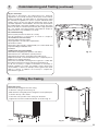
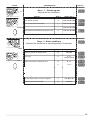
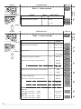
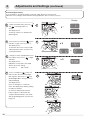
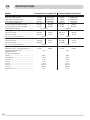
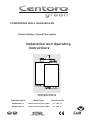
CONDENSING WALL HUNG BOILER
Central Heating - Fanned Flue system
Installation and Operating
Instructions
Centora green system 24
Centora green system 30
GB
Manufactures N°
Model Type
Gas Council N°
200905821037.31
Centora Green System 24 Nat
41 - 980 - 12
200906822037.31
Centora Green System 30 Nat
41 - 980 - 31
IE
c
These instructions are suitable for the CENTORA GREEN System boilers :
Do not forget the Log Book!
Chaffoteaux & Maury supports Benchmark, the heating industry code to ensure the correct installation, commissioning and
servicing of domestic central heating systems.
To The Householder
Make sure you have a completed Log Book for your boiler. This provides a record of the commissioning of your boiler.
It contains important information about your particular installation that may be required by service engineers. The Log Book will
also provide contact details for the installer should you need guidance in the use of this appliance or if there are any problems.
As with your car, your boiler will work more reliably and efficiently if regularly serviced. We recommend an annual service
check. The service history of the appliance will be recorded on the Log Book.
In the unlikely event of any problems with your boiler or system you should first contact your installer. If your installer cannot
resolve the problem he should telephone our national service helpline.
This appliance is a combined appliance for the production of Central Heating (C.H.) and Domestic Hot Water D.H.W.)
This appliance must only be used for the purpose for which it is designed. THe manufacturer declines all responsibility for
improper or negligent use.
A charge may be made if Chaffoteaux & Maury Service is called out to resolve a non-product related fault.
Your statutory rights are not affected.
Do not allow children or inexperienced persons to use the appliance without supervision.
If you smell gas in the room, do not turn on or off light swithces, use the telephone or any other objects that might cause
sparks.
Open doors and windows to ventilate the room.
Shut the gas mains tap (on the gas meter) or the valve of the gas cylinder and call your Gas Supplier immediately.
If you are going away for a long period of time, remember to shut the mains gas tap or the gas cylinder valve.
Before any intervention within the boiler it is first necessary to isolate the electrical power supply by turning the
external switch to “OFF”
TO CONTACT C&M SERVICE, PLEASE CALL THE NATIONAL WARRANTY HELPLINE ON:
0870 600 9888
To The Installer
As part of the commissioning of this appliance it is vital that the Log Book is completed and given to the Householder. Please
ensure that your customer is aware of the importance of keeping the Log Book safe as a record of the installation and the
appliance service history.
Please ensure that your customer is aware of the correct operation of the system, boiler and controls.
CUSTOMER CARE
The MTS Group, as a leading manufacturer of domestic and commercial water heating appliances is committed to providing
high quality products and a high quality after sales service. If it is necessary to contact an engineer, then telephone the
national warranty helpline 0870 600 9888.
Advice on installation or servicing can also be obtained by contacting the Technical Department on:
Tel: 0870 241 8180
Fax: 01494 459775
GUARANTEE
The manufacturer’s guarantee is for 12 months from the date of purchase. The guarantee is invalidated if the appliance is not
installed in accordance with the recommendations made herein or in a manner not approved by the manufacturer. To assist us
in providing you with an efficient after sales service, please return the guarantee registration card enclosed with the boiler
without delay.
2
STATUTORY REQUIREMENTS
The installation of this appliance must be carried out by a CORGI Registered person or other competent person and in
accordance with the requirements of the Gas Safety (Installation and Use) Regulations and the rules in force.
In GB it is necessary to comply with the Water Supply (Water Fittings) Regulation 1999, for Scotland, The Water Bylaws 2000,
Scotland. The Centora Green is an approved product under the Water Regulations.
To comply with the Water Regulations, your attention is drawn to The Water Regulations guide published by the the Water
Regulations Advisory Scheme (WRAS) gives full details of the requirements. In IE the requirements given under the current
edition of I.S.813 must be followed. installation must also comply with the current bylaws of Local Water Undertakings.
Installation should also be carried out in accordance with Building Regulations, Local Authority Building Standards (Scotland)
Regulations and current editions of the following British Standards Codes of practice: BS 7593, BS 5440 parts 1 and 2, BS
5449, BS 7593, BS 6798, BS 5546, BS 7074, BS 7671 and document IGE/UP/7.
In the Republic the Republic of Ireland the installation should be carried out in accordance with the following codes of practice:
I.S.813 Domestic Gas Installation, the following BS Standards give valuable information: BS 5546, BS 5449, BS 7074 and BS
7593.
The electrical connections must be made in accordance for GB with current I.EE. Wiring Regulations, in Scotland with the
electrical provisions of the Building Regulations applicable in Scotland, the Safety Document 635 The Electricity at Work
Regulation and in the Republic of Ireland in accordance with I.S.813 and the current ETCI rules.
The Centora Green does not contain any asbestos or asbestos products, or mercury derivatives. Additional CFC’s have not
been used in this product.
The appliance does not contain any potential hazard in relation to the COSHH regulations.
If there is a possibility of the incoming mains water pressure exceeding 10 bar then a suitable pressure limiting valve must be
fitted where pressures exceed 6 bars a pressure limiting valve is preferred.
Precautions: During servicing, keep the dust generation to a minimum and avoid inhaling any dust and contact with the skin
and eyes. Normal handling and use will not present any discomfort, although some people with a history of skin complaints
may be susceptible to irritation. When disposing of the ceramic lining, ensure that it is securely wrapped and wash hands after
contact.
Contents
CUSTOMER CARE
Page
Guarantee ............................................................................................................................................................2
Statutory Requirements .......................................................................................................................................2
Contents ...............................................................................................................................................................3
INTRODUCTION ..................................................................................................................................................4
INSTALLER’S INSTRUCTION .............................................................................................................................5
1 DESCRIPTION.................................................................................................................................................5
2 DIMENSIONS .................................................................................................................................................6
3 HYDRAULIC DATA .........................................................................................................................................6
4 INSTALLATION REQUIREMENTS .................................................................................................................7
Location ...................................................................................................................................................7
Flue ..........................................................................................................................................................7
Ventilation ................................................................................................................................................7
Gas Supply .............................................................................................................................................7
Electrical Supply ....................................................................................................................................7
Showers ...................................................................................................................................................7
Flushing and Water Treatment ...............................................................................................................7
System Controls ......................................................................................................................................7
3
5 INSTALLING THE BOILER ...............................................................................................................................8
Method of positioning the boiler on th wall...............................................................................................8
Connecting the boiler to the system.........................................................................................................8
Safety valve and condensats drains ........................................................................................................8
Fitting the horizontal flue .........................................................................................................................8
6 ELECTRICAL CONNECTIONS ....................................................................................................................10
Making the Electrical Connections ........................................................................................................10
7 COMMISSIONING AND TESTING ................................................................................................................10
Pre-commissioning ................................................................................................................................10
DHW ......................................................................................................................................................10
Central Heating .....................................................................................................................................10
Lighting the boiler...................................................................................................................................10
By pass and pump .................................................................................................................................11
Post Commissioning ..............................................................................................................................11
Handing over to the Householder .......................................................................................................11
8 FITTING THE CASING ..................................................................................................................................11
9 ADJUSTEMENTS AND SETTINGS ..............................................................................................................12
10 INCORRECT FUNCTION .............................................................................................................................17
11 GAS CONVERSION .....................................................................................................................................17
USER’S INSTRUCTIONS
Page
12- CONTROL PANEL ......................................................................................................................................18
13- HOW TO USE ..............................................................................................................................................19
Switching on ........................................................................................................................................19
Switching on Central heating ................................................................................................................19
Switching on the Domestic Hot water ...................................................................................................19
Switching on the Domestic Hot water and Central Heating together ....................................................19
Stand by mode ......................................................................................................................................20
Turn off the boiler ..................................................................................................................................20
14 MAINTENANCE ............................................................................................................................................20
15 GUARANTEE ................................................................................................................................................20
16 PRACTICAL INFORMATION ........................................................................................................................20
17 GAS CONVERSION .....................................................................................................................................21
18 INCORRECT FUNCTION .............................................................................................................................21
19 TECHNICAL DATA .......................................................................................................................................22
This instruction booklet is especially designed for appliances installed in the The United Kingdom and The
Republic of Ireland
INTRODUCTION
The CENTORA GREEN SYSTEM is a fully automatic, wall mounted, low water content condensing system boiler. It
is a room sealed, fan assisted, balanced flued appliance providing central heating. It has electronic ignition and is
suitable for all modern electrical control systems. The boiler is designed for sealed systems only and a circulating
pump, expansion vessel together with a pressure gauge and safety valve are included within the boiler.
The standard horizontal flue kit is suitable for lengths 300 mm minimum to 600 mm maximum and includes an
elbow adapter that can be rotated through 360 ° . The horizontal flue can extend up to 3 metres using 1 metre
flue extension kits. 45 ° and 90° flue bends are also available as accessories.
4
INSTALLER’S INSTRUCTIONS
1
Description
1.- Steel chassis complete with expansion vessel
2.- Sealed chamber
3.- Burner and heat exchanger assembly
4.- Air / gas connection
5.- 24 V modulating fan
6.- Gas valve
7.- Ignition electrode
8.- Ionisation probe
9.- Ignitor
10.- Combustion products manifold
11.- 24 V transformer
12.- Siphon
13.- Electrical box
14.- Pump
15.- Shunt plate
16.- Pressure gauge
18.- Automatic air separator and automatic vent
19 - Central heating flowswitch
21.- Central heating control thermistor
23.- Overheat sensor
42.- Silencer
10
11
7
2
9
3
8
4
12
6
5
42
23
15
18
1
19
21
13
14
16
Fig. 1
Fig. 2
33
34
35
36
24.- Display
27.- Setting key
28.- Setting key
29.- Central Heating switch
30.- Green indicator – Central Heating mode ON
31.- Central Heating temperature reducing key
32.- Central Heating temperature increasing key
33.- Green indicator – Power ON
34.- Orange indicator - Burner ON
35.- Red indicator - Lock out / flame failure
36.- Reset key
Fig 3
32
31
29
30 24
27
28
5
2
Dimensions
Outer case dimensions :
440 (minimum space required 450)
- Width :
850
- Height :
- Depth :
380 (24kW) - 405 (30 kW)
required
450
minimum space
450 mini
pour entretien
With packaging :
24
30
43 kg
45,5 kg
360
440
50
67
All dimensions in mm
850
737
212
235
232
L
NJ
I
Safety valve C/H and condensate
J
Heating flow
L
Gas supply
N
Heating return
Minimum clearances :
- Both sides
- Above casing
- Below casing
- Front ( for servicing)
- Front (in operation)
32
24380
: 380
30 : 405
Safety valve
center line
108 108 88
The boiler is suitable
for the flue types:
• type C 13
• type C 33
• type C 53
J
L
N
Ø 100
143
170
Ø 80
I
Ø 80 Ø 80
Ø 80
Ø 80
Ø 125
Ø 125Ø 125
Ø 100Ø 100
143 143
Type C 13
Type C 33
Type CType
32 xx
C 32 xx
TypeType
C 12 C 12
Type C 32 xx
Type C 12
Ø 80
120
120
120Ø 80
250 250
250
225 206 206
206
Fig. 4
5 mm
170 mm
200 mm
500 mm
5 mm
Ø 80
Ø 80
250
250
250
Type C 53
Type C Type
32 xy C 32 xy
Type C 32 xy
Hydraulic Data
3
Pump head available
Hauteur manométrique
mCE
6
Minimum
flow(robinets
rate (with
all heating thermostatic
valves closed)
Débit mini
thermostatiques
fermés)
5
GV
F
4
The chart (fig. 5) shows the pump head available regarding
the flow rate. GVF means high speed by-pass closed, PVF
means low speed by-pass closed, GVO means high speed
by-pass fully open, PVO means low speed by-pass fully
open.
3
PVO
1
0
PV
F
GVO
2
100
200
300
400
500
The boiler comprises a double speed pump and an
adjustable by-pass.
600
700
800
900
1000
1100
l/h
Fig. 5
Pump head chart available at the outlet of the boiler
For adjustment procedure, please refer to § 8.
The minimum flow rate to insure a correct functioning of the
should be over 300 l/h (with thermostatic valves fully
closed)
Pf Pression
froid pour
le circuit
chauffage
(en cold
bar) (in bar)
Central àheating
initial
pressure
when
2,0
Maximum water capacity of Central Heating system :
1,9
1,8
1,7
The expansion vessel is pre-charged to 0.7 bar (10 lb/in 2 ).
40°C
1,6
1,5
1,4
The vessel is suitable for systems up to 145 litres capacity.
50°C
1,3
1,2
70°C
1,1
1,0
0,9
0,8
0,7
For systems of greater capacity an additional expansion
vessel will be required. Refer to the chart below and BS
7074 pt 1 or BS 5449.
60°C
80°C
20
40
60
80
100
120 140
160
180 200
220
240 260
Capacité
maximale de l'installation (en litres)
System capacity
chart
Fig. 6
6
C liter
The minimum initial pressure of the system should be over
0.7 bar (1 to 1.5 bar is recommended).
4
Installation Requirements
Location
The boiler can be installed on any suitable internal wall.
Provision must be made to allow the correct routing of the flue
and siting of the terminal to allow the safe and efficient
removal of the flue products. A compartment or cupboard may
be used provided that it has been purpose-built or modified for
the purpose. It is not necessary to provide permanent
ventilation for cooling purposes. Detailed recommendations
are given in BS 5440 pt 2. If it is proposed that it is installed in
a timber framed building then reference must be made to
British Gas Document DM2, or advice sought from CORGI.
Avoid to install the boiler where the air inlet can be polluted
by chemical products such as chlorine (swimming pool aera),
or ammonia (hair dresser), or alcalin products (launderette)
Flue
Detailed information on flue assembly is contained in the
appropriate starter pack.
The boiler must be installed so that the flue terminal is
exposed to the free passage of external air at all times. It must
not be allowed to discharge into another room or space such
as an outhouse or closed lean-to. The minimum acceptable
clearances are shown below:
pole isolating switch with contact separation of at least 3 mm
on both poles. Alternatively, a fused 3 Amp. 3 pin plug and
unswitched socket may be used, provided it is not used in a
room containing a bath or shower. It should only supply the
appliance.
The boiler is suitable for sealed systems only. The maximum
working pressure for the appliance is 10 bar. All fittings and
pipework connected to the appliance should be of the same
standard. If there is a possibility of the incoming mains
pressure exceeding 10 bar, particularly at night, then a
suitable pressure limiting valve must be fitted.
The boiler is designed to provide hot water on demand to
multiple outlets within the property. If there is a requirement
for greater demands, for example if the property has several
bathrooms and cloakrooms, a vented or unvented hot water
storage system may be used.
Showers
Any shower valves used with the appliance should be of a
thermostatic or pressure balanced type. Refer to the shower
manufacturer for performance guidance and suitability.
Flushing and Water Treatment
The performance of the appliance could be impaired by
system debris or the effects of corrosion. The system must
be flushed thoroughly to remove metal filings, solder,
machining oils and other fluxes and greases before
connecting the boiler. If it is an existing system, an
appropriate flushing and descaling agent should be used.
Refer to BS 7593 (1992) for guidance. For more information
on the use of corrosion inhibitors, flushing and descaling
agents, advice can be sought from the manufacturers of
water treatment products such as:
- A Directly below an opening, window, etc
300 mm
- B Above an opening, window, etc
300 mm
- C Horizontally to an opening, window, etc
300 mm
- D Below gutters, soils pipes or drain pipes
75 mm
- E Below eaves
200 mm
- F Below balconies or car port roof
200 mm
- G From a vertical drain pipe or soil pipe
150 mm
- H From an internal or external corner
300 mm
- I Above ground roof or balcony level
300 mm
- J From a surface facing the terminal
600 mm
- K From a terminal facing the terminal
1200 mm
- L From an opening in the car port into the dwelling 1200 mm
- M Vertically from a terminal on the same wall 1500 mm
Fig. 7
- N Horizontally from a terminal on the same wall 300 mm
- Q Fixed by Ubbink Rolux 4 GM flue terminal
Q
It may be necessary to protect the terminal with a
Q
guard. Reference should be made to the Building
I
Q
D,E
Regulations for guidance. Suitable guards may be
F
obtained from the following manufacturer:
N
B
Quinnel Barret & Quinnel Wireworks
C
J
M
L
Old Kent Road
N
A
H
G
London SE15 1NL
I
H
M
Tel: 0171 639 1357
K
Ventilation
Betz Dearborn Ltd
The room in which the boiler is installed does not require specific
Foundry Lane
ventilation. If it is installed in a cupboard or compartment
Widnes
permanent ventilation is not required for cooling purposes.
Cheshire
Gas Supply
WA8 8UD
The gas installation and soundness testing must be in
Tel: 0151 424 5351
accordance with the requirements of BS 6891.The boiler
Fernox Manufacturing
requires a 22 mm supply. Ensure that the pipe size is
Britannica Works
adequate for demand including other gas appliances on the
Clavering
same supply.
Essex
Combustion system protection
CB11 4QZ
The sulphur level contained in the gas should comply with
Tel: 01799 550811
the européan Standards which are :
System Controls
- maximum 150 mg/m3 for a short period in a year
The boiler is electrically controlled and is suitable for most
- average level of 30 mg/m3 during one year
modern electronic time and temperature controls. The
Electrical Supply
addition of such external controls can be beneficial to the
The appliance requires an earthed 230V - 50 Hz supply and
efficient operation of the system. The boiler connections for
must be in accordance with current I.E.E. It must also be
external controls are 24V and so only controls of 24V or that
possible to be able to completely isolate the appliance
have voltage free contacts should be used.
electrically. Connection should be via a 3 amp fused double-
7
5
Installing the Boiler
Please check that you are familiar with the installation requirements before commencing work.(section 6)
The installation accessories described in the following list are included in the boiler packaging.
- Hanging bracket
- A paper template (showing the dimensions of the boiler with 5 mm side clearances, fitting instructions and commissioning
instructions)
- Connection tails
- Screws and wall plugs
- Connection washers and filters
- Installation manual
Method of positioning the boiler on the wall.
The paper template can be used to ensure the correct positioning of kitchen cabinets etc. It also details the commissioning
instructions.
The paper template has to be fixed to the wall and used to locate the position of the hanging bracket and the centre for the flue
hole.
Drill and plug the wall and secure the hanging bracket using the screws provided. Remove the boiler from its packaging as
shown in fig. 8 and unscrew the 4 screws A and remove the casing (Fig. 9).
Place the boiler on the wall on the hanging bracket (Fig. 10).
If required, there is space for all piping to pass behind the boiler. Using Fig. 10 for reference, connect the gas and water pipes
and the valves to the base of the appliance using the tails provided. There is a 190 mm space between the valves and the wall
to make these connections.
Connecting the boiler to the system
- Push in the tabs “P” (fig. 12) on either side of the boiler and pivot the electrical box forward to gain access to the valve
connections
- Remove the yellow caps and connect the boiler to the taps using washers provided in the plastic bag.
2 x fibre washers for the C/H flow and return.
1 x rubber washer for gas connection.
Provision must be made to fill and recharge the system pressure. This can be achieved using a filling loop or other methods
approved by the local water authority.
Safety valve and condensate drains
The pressure relief valve tube is clear silicone. It should terminate below the boiler over a tundish or 22 mm pipe (see I fig 4)
which should in turn discharge safely outside the premises. Care should be taken that it does not terminate over an entrance
or window or where a discharge of heated water could endanger occupants or passers by.
The system should be carefully checked for leaks, as frequent refilling could cause premature system corrosion or
unnecessary scaling of the heat exchanger. The pipe from the siphon 12 (fig. 1) should be connected to a drain is the
conditions described in the relevant Brittish regulations.
External termination via condensate siphon
The condensate drainage pipe should have a minimum diameter of 22 mm, it should be inserted into a suitable acid resitant
pipe - e.g. plastic waste or overflow pipe (refer to BS 6798 : 2000) by at least 50mm, must have a continuous fall and
preferably be installed and terminated within the building.
Pay special attention to not bend the condensates silicone drain pipe such as the flow will be interrupted.
The discharge pipe must terminate in a suitable position:
i) Connecting to an internal soil stack (at least 450mm above the invert of the stack). A trap giving a water seal of at least
75mm must be incorporated into the pipe run, there must also be an air break upstream of the trap.
ii) Connecting into the waste system of the building, such as a washing machine or sink. The connection should be upstream
of the washing machine / sink (if the connection is down stream of the waste trap then an additional trap giving a minimum
water seal of 75mm and an air break must be incorporated in the pipe run as above.
iii) Terminating into a gully below the grid level but above the water level.
iv) Into a soakaway.
NOTE: IF ANY CONDENSATE PIPEWORK IS TO BE INSTALLTED EXTERNALLY, THEN IT SHOULD BE KEPT TO A MINIMUM AND BE INSULATED WITH
A WATERPROOF INSULATION AND HAVE A CONTINUOUS FALL
The condensate flow can reach 2 litres/hour; because of the acidity of the condensate products (Ph close to 2), take care
before operation.
Fitting the Horizontal Flue
Attention ! Before starting the boiler, the siphon 12 fig. 1 must be filled with water. Before fitting the flue terminal onto
the boiler, please poor 1/4 litre of water in the exhaust pipe as shown in Fig. 11.
The instructions for the vertical and biflux (twin pipe) flue options are included with the relevant adapter kits.
The standard flue supplied with the appliance is suitable for lengths from 300 mm minimum to 720 mm maximum.
8
This means for rear flueing, the standard kit will accommodate a maximum wall thickness of 600 mm, and for side flueing a
maximum wall thickness of 587 mm. This takes into account the minimum appliance side clearances of 5 mm.
If the flue is a side exit installation, then calculate the position of the hole with a slope of 5 mm / metre towards
the boiler from the terminal. The flue should rise up slightly to the terminal in order to let the condensate coming back into the
boiler.
Attention ! Use only specific condensation flue kit.
5
Installing the Boiler (continued)
Fig. 8
A
A
A
A
Fig. 9
Fig.10
Fig.11
9
6
Electrical Connections
Making the Electrical Connections
Hinge down the electrical box to gain access to the electrical connections. Push in the tabs P (Fig 12) on either side of the
boiler and pivot the box forward.
Connect the main cable M to live, neutral and earth.
If using a room thermostat or other external control :
Undo the two retaining screws V , remove cover and remove cable clamp. J (right side) (Fig. 13)
Remove connector C from the PCB in the cover
Connect the external control cable in place of the link S on the multipin plug C
Reconnect multipin plug into the socket on the printed circuit board. Secure the cable using the cable clamp and
replace the cover.
Note: The connections should be made so that should the lead be pulled from its anchorage, the current carrying wires
become taut before the earth wire
M
230 V
U12
TH4
J
C82
C81
T14
C34
C84
R16
R12
R137
RL9
BUS
1
Z6
RL7
C78
RL2A
T15
T10
D46
D14
R
D15
D42
R32
R128
T12
D43
D41
R107
RL7A
C79
T11
C28
CALYDRA
R129
J9
D16
R31
D30
R35
R33
R34
C80
R130
R133
T16 R36
12
11
12 SW1 1
11 SW2 2
1.23
R
R25
R29
TR
N
J11
R6
D5
R6a
J1
R119
R118
D35
T9
VITESSE
J2
R115
1
1 230V
1
J4
J1
Z4A
C73
R112
1
R7 R7a
REP COM
TA
1
P
+5V
J7
J3
R113
C75
M/A
U9
8
C
+
RL10
D17
RL13
C
Ph
D36A
RL8
R17
A
L1
R18
C38
R19
D40
C74
D36
Z4
T2A
1
RL6
F1
C1
Socket for
connector
Fig. 13
C
V
Mains
PH N
THERMOSTAT
S
R. ACC
230V
connector
C
1
7
Z7
Z7A
C31
R1
1
OFF ON
OFF ON
MCD
D31
R23
1
+
Fig. 12
TA
R13
R27
PROG
RL2
C52
R9
R8
TH3
C27
R10
J12
+
J5
MOTEUR
R24
C26
R63
2
Commissioning and Testing
Pre-commissioning
Ensure that the system has been adequately flushed.
Purge gas supply of air and test for soundness.
Carry out final electrical tests to ensure the correct polarity and
earthing continuity.
DHW
Open the main cold feed valve 40.
Open all hot taps to purge DHW system.
Check for water soundness.
Check flow rate at the bath tap is set correctly (see technical data).
Central Heating
Open flow and return valves on the boiler 37 and 41 (Fig. 14)
Open the automatic air vent 18 (Fig. 2)
Fill system and vent radiators.
Set system pressure and remove filling loop.
Check for leaks.
Manually check pump is free to turn.
Switch on electrical supply.
Press the Central Heating switch 29 (Fig. 3) to switch on heating
mode.
Press the + key 32 (Fig. 3) to set heating temperature to maximum.
Allow pump to run for several minutes.
10
1
R136
T13
R15
J6
R59
R64
P
R14
C83
R132
1
U11
R140
C25
C51
D32
S
Isolate the electrical supply.
Drain boiler and check water filter for installation debris.
Replace filter and recharge system.
Lighting the Boiler
Inspect the entire gas supply for soudness, including the gas meter,
the gas installation should be in accordance wiith the relevant
standards, in GB this is BS 6891 and in IE this is the current edition
of I.S.813.
Connect gas pressure gauge to test point 39 (Fig. 14).
Turn on the gas supply and boiler gas tap 39 (Fig. 14).
Ensure electrical supply is on.
Ensure all external controls are calling for heat.
Press on Central Heating switch 29 (Fig. 3) to switch on heating
mode.
Press the + key 32 (Fig. 3) to set heating temperature to maximum.
The boiler will light. Allow the boiler to heat system.
Check the inlet gas pressure (working pressure) while boiler is
operating in hot water mode.(Refer to technicaldata).
Check the operation of the boiler controls and safety devices.(see
separate servicing leaflet for details).Set the by pass (refer to the
paragraph bellow).
Re-flush the system to remove any dissolved oils and fluxes.
Recharge system pressure and introduce any water treatment as
required.
7
Commissioning and Testing (continued)
By pass and Pump
The boiler is fitted with a pre-adjusted by pass. Although
adjustment is not normally necessary, the by pass can be reset by
turning screw D (Fig. 14) anticlockwise to open the by-pass using
the chart below for guidance. If used on a system with thermostatic
radiator valves, the flow rate with the thermostatic valves closed
should be adjusted to at least 300 l/hr. The enclosed charts indicate
the residual head of the pump available for the system. The pump
fitted on the boiler is a double speed model. (GV = High speed and
PV = low speed). The speed setting is described in chapter 9.
Speed selection is only available in C.H. mode.
1
3
0
4
bar
16
Post Commissioning
Ensure system pressure has been set correctly.
Set all parameters of the boilers as shown in chapter 9
ADJUSTMENTS AND SETTINGS.
Set boiler thermostat and controls.
Set programmer to householder’s requirements.
Set external controls.
Ensure the Logbook is fully completed with your contact details and
required readings and details of the
installation.
37
41
39
D
Handing Over to the Householder
Fig. 14
Demonstrate the lighting and operation of the boiler.
Demonstrate how to maintain the system pressure.
Demonstrate the operation and setting of the built-in clock.
Explain the benefits of annual maintenance by a competent person.
Explain how to register guarantee.
Ensure the Householder countersigns the Log Book to confirm that
these demonstrations have been carried out and understood.
For IE, it is necessary to complete a “Declaration of Conformity” to
indicate compliance to I.S.813. An example of this is given in the
current edition of I.S.813. An example of this is given in the curent
edition of I.S.813. in addition it is necessary to complete the
“Benchmark” Log Book.
8
Fitting the Casing
Fitting the casing
T
Remove the protecting film from the casing :
T
- Position the casing as shown in Fig. 16
- Slide down the casing and put the casing holes on the plastic pins
1
located on the top of the chassis
- Control the correct position of the casing onto the boiler
- Tighten the 4 screws located at the bottom as shown in Fig. 15.
2
Fig.15
A A
A
A
Fig. 16
11
9
Adjustments and Settings
The boiler is delivered with a pre setting values described in menus 3 and 4.
All settings can be changed by the installer or a qualified person. To gain access to the setting keys please, open the front
door P. (Fig. 17)
P
DISPLAY
Menu
access
Menu key
&
Setting key
Left side
Fig. 17
Right side
Key +/for Parameter
Setting
3 rd digit
DISPLAY
2 nd digit
1 st digit
To gain access to setting menus press simultaneously on
and
keys on the Right. side during 5 seconds. (fig. 18). Menu
1 is displayed.
Changing the menu :
key on the Left. side) (Fig.17). The menu number is displayed for 3 seconds. Press on menu key
Press on Menu key (
to change for the next menu.
Changing section in a menu (available only for menu 3 and 4 :
Press on
or
key on the Right side to change from a section to the previous or the next in a menu.
Note : When you arrive at the last section of a menu, pressing on + key will change for the the 1st section. When you are
at the first section, pressing on – key will change for the last section of the menu.
Setting a parameter in a section:
Press on setting key (
key on the Left side) to enter in modification mode. The 2nd and 3rd digits are flashing Press on
or
on the Right side to select the correct value then press on Setting key to valid
this modification and to get out from setting mode. The 2nd and 3rd digit stop flashing.
Recalling the basic configuration:
Select menu 3 or 4 then press together on
flash CM
key on the Right side and setting key for more than 5 seconds. The digits will
for a while to indicate that the operation is completed.
Erasing the default register :
Select menu 1 then press together on
flash CM
+ key on the Right side and setting key for more than 5 seconds. The digits will
for a while to indicate that the operation is completed.
Note : To exit from setting mode, leave the boiler for approx. 1 minute then the computer will switch back to user mode.
12
ACTION
DISPLAY
CONFIGURATION
Menu - 1 - Default register
Record the last 10 defaults
5”
Section
x times
Digit 1
Digit 2 and 3
Last default occured
0•
code from 01 to 99
Last but one default occurred
1•
code from 01 to 99
...
...
code from 01 to 99
Last default occurred before the previous one
9•
code from 01 to 99
Note -- is displayed if no default is recorded.
Menu - 2 - Boiler conditions
Indicates the conditions or the configurations of the boiler
once
x times
Section
Digit 1
Digit 2 and 3
Software version of display PCB
0•
10 to 99
Flue type
2•
1 : FF
variable speed
Room thermostat is calling for heat
3•
0 : no
3•
1 : yes
4•
0 : DHW
4•
1 : CH
DHW flow temperature in Celsius degrees
5•
from 00 to 99
CH flow temperature in Celsius degrees
7•
from 00 to 99
Software version of main PCB
9•
10 to 99
Theoretical position of the 3 way valve
13
ACTION
DISPLAY
CONFIGURATION
once
Section
Digit 1
Under floor heating system
0
Factory
setting
Menu - 3 - Boiler options
Digit 2 and 3
0 : no
1 : yes
x times
DISPLAY
CONFIGURATION
Menu - 4 - Boiler settings
Section
Digit
1
Digit
2 and 3
0
0 : Burner only
0
1 : Burner and pump
1
0 : High speed
1
1 : Low speed
Pump post circulation duration
2
0,0 min
From 0 to 5 minutes by step of 0.5 min.
2
0,5 min
2
1,0 min
2
5,0 min
4
50°C
4
80°C
CH anti cycling delay
8
0,0 min
From 0 to 7 minutes by step of 0.5 min.
8
0,5 min
8
2,5 min
8
5,0 min
9
Value from
0 to 10
9
Value from
0 to 10
once
Room thermostat operation
x times
Pump speed
Maximum Central Heating flow temperature
CH maximum output limitation
Model 24
From step 0 (P. min.)
8 kW
to step 10 (P. max.) 24 kW
Model 30
From step 0 (P. min.)
9 kW
to step 10 (P. max.) 28 kW
14
Factory
setting
ACTION
ACTION
DISPLAY
CONFIGURATION
Menu - 5 - Combustion rate control mode
press once
Effect
wait 5 ”
Combustion rate control mode OFF
Switching on the combustion rate
control mode. Central heating output
reach the maximum power set in
menu 4 section 9.
Central heating temperature is
displayed in celsius degrees.
The 3 dots indicate that the
combustion rate control is ON at
maximum output.
XX
Switching the combustion rate
down to minimum power.
Central heating temperature is
displayed in celsius degrees.
The dot indicates that the
combustion rate control is ON at
minimum output.
XX
Switching on the combustion rate to Central heating temperature is
maximum output set in menu 4
displayed in celsius degrees.
section 9.
The 3 dots indicate that the
combustion rate control is ON at
maximum output.
XX
press once
press once
press once
Display
Switching off the combustion rate
control mode.
press once
Locking conditions of the combustion rate control mode :
- boiler in stand by mode
- room thermostat is not calling for heat
- room thermostat is calling for heat but the maximum temperature is reached
- boiler in lockout mode
- after a reset or if the main supply fails
- end of the mode if operator leave menu 5
- after 15 minutes if there is no actions on keyboard
Note : As soon as the combustion rate control mode is on, Central Heating key is inactive.
15
9
Adjustments and Settings (continued)
CH heat output setting :
If you would like to change the setting of C/H heat output, please proceed as follow :
(NOTE: the factory setting is 18 kW and the following explanation refer to menu 4 section 9)
Display
1
- Switch to installer mode, press key
and
1
5”
on the Right side for 5
seconds.
The display shows :
-1- then 0•-- if there is no default in the
default register.
2
- press 3 times on menu key
(on the
2
Left side ) to gain access to menu -4-,
x3
The display shows :
-4- then the value set for section 0 ( 00
or 01 respectively Action on burner only
or
or pump and burner)
3
- change for section 9 (Adjustment of CH
heat output). Press on key
on Right
side times.
3
The display shows :
(906 which corresponds to the 18 kW
which is the factory setting)
9 = section 9
4
06 = 18 kW
- press on setting key
(on the Left
side) one time, the 2nd and 3rd digits
flash together. Then press on
key
on the Right side to change for 3.0 on
2nd and 3rd digit.
The display shows :
Press on setting key to confirm the
value. The display stops flashing. Setting
procedure is finished.
To exit from setting mode, leave the
boiler for approx. 1 minute then the
computer will switch back to user mode.
After programming please close the door
P (Fig. 17)
16
4
x9
Incorrect Operation
10
In case of problem, or when the boiler has to display a message, the display flashes 2 digits. Please refer to the table bellow
to diagnose the default.
For default 01 and 03, the red indicator 35 is alight (Fig.18)
Overheating lock out
FAULT
35
Fig. 18
Code
display
Fault description
01
Overheating lock out
03
No flame detection
05
Anti freezing system, pump on
06
Anti freezing system, pump and burner on
07
No water circulation in primary circuit
08
No water in the primary circuit
11
Central Heating thermistor faulty (open circuit)
12
Central Heating thermistor faulty (open circuit)
18
Attempt to re light
20
Wiring problem
23
Fan speed too low
24
Fan control system defective
31
Communication problem with the display PCB
32
Communication problem with the main PCB
11
Information on functioning
Gas Conversion
If the boiler is not set for the gas type, conversion kits are available. To convert the boiler, please use exclusively Chaffoteaux
& Maury parts and proceed as it is mentioned in the instruction manual provided with the conversion kit.
17
USER’S INSTRUCTIONS
Control Panel
12
34
35
33 36
24
16
32 31
29 30
27
Fig. 19
28
Control panel (Fig. 19)
31.- Key to reduce the Central Heating temperature
16.-
32.- Key to increase the Central Heating temperature
Pressure gauge
24.- Display temperature adjustment
33.-
Green indicator - Power ON
27.- Setting key
34.-
Orange indicator - Burner ON
28.- Setting key
35.-
Red indicator - Lock out / flame failure
29.-
36.- Reset button
Switch for Central Heating mode
30.- Green indicator Central Heating
37
39
Fig. 20
Connecting bracket Taps shown in Open position(fig. 21)
37 : Central heating flow isolating valve
39 : Gas service tap
41 : Central heating return isolating valve
43 : Central heating pressure relief valve
18
41
43
13
How to Use
Switching on
1. Check that pressure in central heating system is above 0.7 bar and below 1.5 bar with the pressure gauge 16.
2. Check that the gas service tap is opened at the gasmeter and main power is on. Green indicator
Power ON
33.
3. Open the gas tap 39 (Fig. 20).
The boiler is now ready to use.
Attention ! If the boiler stays a long time without working, some air in the gas pipe can hinder the first lightings. (please refer
to Section 18 Incorrect Function)
Switching on Central heating
Press on key 29
, the green indicator 30 will light and the display will show the Heating
flow temperature.
Keys 31
and 32
allow to adjust the temperature required in the Central Heating
system regarding the weather conditions.
• press
to increase temperature when weather is cold
• press
to reduce temperature when weather is fair
During the temperature setting operation the display will flash.
If the room thermostat is calling for heat, a dot will be displayed at the bottom of the 3rd digit
19
13
How to Use (continued)
Stand by mode
A fixed digit at the centre of the display and the green indicator 33 on
Putting the boiler in stand by mode and anti freeze system. :
Press on key 29
, to switch off CH mode. The green indicator 30 will stop.
During the all duration of the stand by mode, an automatic anti-sticking system will switch on the pump for 1
minute and make a movement of the 3 way valve each 23 hours.
The stand by mode will disable the anti-freeze function of the room thermostat (if fitted). To leave the room
thermostat anti freeze system operative, please let the Central Heating mode on.
The boiler is equipped with an automatic anti freeze system which permanently on.
If the Central Heating temperature decrease bellow 7°C, the pump will start.
If the Central Heating temperature decrease bellow 4°C, the pump and the burner will start.
Turn off the boiler
- Press on key 29
, to switch off CH mode. The green indicator 30 will stop
- Switch off the main electrical supply
- Shut off the gas service tap 39 (fig. 21)
Note : In this conditions, the anti-freeze system is inoperative
14
Maintenance
As with your car, your boiler will work more reliably and efficiently if regularly serviced. We recommend an annual service
check. The service history of the appliance will be marked on the logbook.
15
Guarantee
The manufacturer`s guarantee is for 12 months from the date of purchase. The guarantee is voidable if the appliance is not
installed in accordance with the recommendations made herein or in a manner not approved by the manufacturer. To assist us
in providing you with an efficient after sales service, please return the guarantee registration card enclosed with the boiler without delay.
16
Practical Information
Pump anti-sticking device
When the boiler is switched on, an automatic anti-sticking system will switch on the pump for 1 minute and make a movement
of the 3 way valve each 23 hours. This is a normal functioning.
Precaution to avoid freezing
We recommend you to contact your installer or local service centre to take precautions adapted to your system.
Chose one of the following solution :
- 1) Drain completely the Central Heating system
- 2) Protect the Central Heating system with anti freeze chemical products and verify periodically the concentration
- 3) Leave the Heating mode switched on and set the room thermostat to anti-freeze mode (between 5 and 10°C)
- 4) Leave the boiler in stand by-mode, the anti-freeze device will switch on the pump and the burner if necessary.
20
Helpful suggestions
-
Periodically check the system pressure using the pressure gauge and make sure that the pressure is between 1.0 and 1.5
bar when the system is off and cool. If the pressure is below the minimum recommended value, the pressure must be
brought into the acceptable range. Consult your installer for checking and refilling the system.
If the pressure level drops on a frequent basis, it is likely there is a water leak in the system. If this is the case, your
installer must inspect the system.
-
The outer panel of the boiler’s case must only be cleaned with a damp cloth, do not use abrasive cleaners. The control
panel can be wiped with either a damp or dry cloth. Spray polishes must not be used on the control panel surface or
knobs. Care must be taken in preventing any liquid entering the appliance.
17
Gas Conversion
This appliance is suitable for Natural gas or LPG. A gas conversion must be made by a competent person.
18
Incorrect Operation
Fault
Cause
The boiler doesn’t start
No gas, no water or no electricity
Solution
Check the water pressure in the central
heating system and external electrical
supply, check that the gas supply is on,
should there still be a problem contact
your local service centre.
Air in the gas pipe
Contact your local service centre.
Room thermostat switched off
Turn up the room thermostat
Wait for a few minutes
Press the reset button 36 (fig.21) the red
led will go out and the boiler attempts to
re-light.
If the red indicator lights too frequently,
please call your local service centre.
Red indicator alight
Ignition lockout
Noises in CH system
Air presence in CH system or.
Insufficient pressure
Purge of air the system and rise up the
system pressure (chapter 8)
Radiators rise in temperature During
summer season
Gravity effect in the CH system
Close the heating flow isolating valve.
Don’t forget to open it again when you
will start heating.
If these solutions do not cure the fault, call a qualified professional
21
19
Technical Data
Model
Appliance category...........................................
Centora Green System 30
II 2H3P
II 2H3P
Heat gross input C/H maxi ...............................
Heat output C/H 50°/30° maxi ..........................
Heat output C/H 80°/60° maxi ..........................
C/H operating temperature...............................
C/H circuit pressures Min operating .................
C/H circuit pressures Max operating ................
Compartment ventilation ..................................
27.8 kW
94534 Btu/h
26 kW
88732 Btu/h
24 kW
81907 Btu/h
80°C max
25°C min
0.7 bar
10 Ib/in2
2.5 bar
36.3 Ib/in2
not required
31.6 kW
107843 Btu/h
30 kW
102383 Btu/h
28 kW
95557 Btu/h
80°C max
25°C min
0.7 bar
10 Ib/in2
2.5 bar
36.3 Ib/in2
not required
Natural gas G20
Gas rate C/H max ............................................
Gas rate C/H mini.............................................
Gas valve restrictor diameter ...........................
2.64 m3/h
0.87 m3/h
without
93 ft3/h
31 ft3/h
3.01 m3/h
1 m3/h
Propane L.P.G G31
Gas rate C/H max. ...........................................
Gas rate C/H mini.............................................
Gas valve restrictor diameter ...........................
1.94 kg/h
0.64 kg/h
4.40 mm
36 ft3/h
12 ft3/h
Safety discharge ..............................................
Expansion vessel - Pre-charge pressure .........
Net capacity at 3 bar in liter..............................
Adjustable by-pass
Electrical characteristicis
Supply ..............................................................
Consumption ....................................................
Protection .........................................................
Fuse F1 ............................................................
Fuse F2 ............................................................
Fuse F3 ............................................................
Fuse F4 ............................................................
External controls ..............................................
22
Centora Green System 24
3 bar
0.7 bar
106 ft3/h
35 ft3/h
without
2.21 kg/h
0.73 kg/h
41 ft3/h
13 ft3/h
4.8 mm
43.5 Ib/in
9.4Ib/in2
2
3 bar
0.7 bar
43.5 Ib/in2
9.4Ib/in2
5.44
5.44
230 v
150 w
IP 44
2A
1,25 A
0,315 A
0,250 A
24 v.
230 v
150 w
IP 44
2A
1,25 A
0,315 A
0,250 A
24 v
23
This appliance is suitable for Natural gas or LPG. A gas conversion must be made by a competent person.
Manufacturer:
Chaffoteaux & Maury - France
Commercial subsidiary:
MTS (GB) Limited
MTS Building
Hughenden Avenue
High Wycombe
Bucks HP13 5FT
Telephone:
Fax:
Internet:
E-mail:
(01494) 755600
(01494) 459775
www.chaffoteaux.co.uk
[email protected]
Technical Support Help Line:
Customer Service Help Desk:
0870 241 8180
0870 600 9888
1310360g- 3/2004
Chaffoteaux & Maury are continuously improving their products and therefore reserve the right to change specifications without
prior notice and accepts no liability for any errors or omission in the information contained in this document.