1
5750-212
Revision A
Page 1
5750-212
Revision A
I.V./700
Ink Jet Printer
Service Manual
The information contained in this manual is
correct and accurate at the time of its publication. Diagraph reserves the right to change
or alter any information or technical specifications at any time and without notice.
© 1999 Diagraph, Inc. All rights reserved.
Printed in the United States of America
5750-212
Revision A
Page 2
TABLE OF CONTENTS
Basics
Basics ...................................................... 2
Product Specifications .................................. 3
Components ............................................... 4
Keypad Assignments..................................... 5
Keystrokes with Command Prompts............. 6-11
Maintenance .................................................
Loading Ink ........................................ 12
Purging All Channels ............................ 13
Purging with Conditioner ...................... 14
Purging Individual Channels .................. 15
Adjusting Screen Contrast ..................... 16
Troubleshooting ..................................... 17
Service Parts .......................................... 29
Test Results ........................................... 33
Appendix A: Service Parts Instructions ... 36
5750-212
Revision A
Page 3
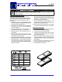
Product Specifications
Controller / Ink Delivery System
Two models
Weight
English/European 15 lb. (6.8 kg)
English/Asian 15 lb. (6.8 kg)
Microprocessor
32-bit CMOS 68332
LCD
European display: 20 characters, 5 x 8 matrix, European character set
Asian display: 20 characters, 5 x 8 matrix, Japanese character set
LED
Four status
Keypad
Twelve special function keys; numeric keypad; QWERTY array with
ALT key combinations for multiple character sets; four keys for cursor
control.
Message Storage
Ninety-nine 50-character messages
Languages
European: English, French, German, Italian, Spanish
Asian: English and selected Katakana & Kanji characters
Enclosure
Injection molded thermoplastic
Ink Capacity
Can, 13.5 fluid ounces (400 ml.)
Electrical
100V - 240V, 0.7A 50/60 Hz
Dimensions
8.75 in x 6.25 in x 3.25 in (222 mm x 159 mm x 83 mm)
Printhead
Resolution
7 dots/inch vertical, 12 dots/inch horizontal
Dot Diam. Range
0.100-0.125 in (2.54 - 3.175 mm)
Rec. Throw Distance
0.50 in max. at 50 ft/min; 12.7 mm at 15.24 m/min
0.625 in max at 150 ft/min; 1.59 mm at >45.72 m/min
Max. Line Speed
250 ft/min (76.2 m/min)
Character Height
.50 in (12.7 mm) 7 dot
.36 in (9 mm) 5 dot
Ink Colors
Black, red, green, blue, yellow, orange
Ink Line Pressure
20-90 psi (1.4 -6.2 bar)
Operating Temperature
40º to 110º F (4.4º to 43.3º C)
Photosensors
Two with up to .75 in max. read distance
Ink Compatibility
All inks are miscible, water-based, nonflammable and odorless
Ink Compliance
I.V./700 type inks contain no chemicals reportable under SARA
section 313. These inks meet CONEG legislation for printing onto
packaging components. All components of these inks are included in
the European inventory of existing chemical substances (EINECS
list).
Dimensions
3.2 in x 3.4 in x 6.4 in (81 mm x 87 mm x 164 mm)
System Compliance
UL / CE / CSA
Options
External photosensor model available.
5750-212
Revision A
Page 4
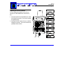
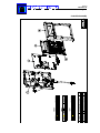
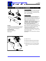
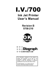
I.V./700 Components
5750-212
Revision A
Page 5
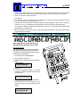
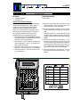
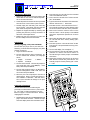
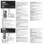
Keypad Assignments
DISPLAY
1 Two-line, twenty character per line, liquid crystal display (LCD).
2
3
4
5
1
LEDs
Power LED; lit when the printer has power.
Photo-eye LED; on while a product passes by.
Print LED; lit when the printer is in print mode.
Ink out LED; blinks when the ink can is out of
ink.
2
3
5
4
6
7
9
8
10
11
ABC
ABC
6
7
8
9
10
11
12
13
14
15
16
17
FUNCTION KEYS
PRINT: Starts and stops printing.
EDIT: Create, edit or delete a message.
PURGE: Purge all ink channels; with ALT (24),
it purges single channels.
MESSAGE INDENT: Sets the message indentation from the leading edge of the product.
FONT: Selects the font to print.
TIME: Inserts the printed time into a message.
With ALT (24), it inserts a work shift code.
SET-UP: For configuration of the system.
INFORMATION: Provides status and setting
information.
DOT SIZE: Increases or decreases all dot sizes
at once.
CHARACTER WIDTH: Changes the width of
printed characters which produces changes in
the length of printed messages.
DATE: Inserts the date into a message. With
ALT (24), it inserts an expiration date.
ITEM COUNT: Inserts the item count into a
message. With ALT (24), it inserts pallet
counts.
NUMERIC KEYPAD
18 Keys for number entry which will show alternate characters when scrolled with the arrow
keys (22).
EDIT KEYS
19 DELETE: Erases the character under the cursor and does not repeat.
20 BACKSPACE: Deletes the character to the left
of the cursor and will continue to delete when
held down.
21 ENTER: Completes entries and enacts changes.
i
12
12
123
17
7
8 13 9 14
4
5
6
19
1
.
2
0
3 20
- 21
Q
W
E
R
T
Y
U
I
O
P
A
S
D
F
G
H
J
K
L
:
Z
X
C
V
B
N
M
/
(
“
18
15 16
22
23
Alt
24
26
25
ARROW KEYS
22 Keys that provide cursor movement and screen scrolling.
ALPHABETIC KEYS
23 Keys for character entry. Each character will show
alternate characters when scrolled with the up and
down arrow keys.
ALTERNATE KEYS
24 ALT: Provides alternate characters and functions when
used in combination with other keys.
25 ENTER: This key duplicates the function of key 21
SPACE BAR
26: Enters spaces in messages; can be scrolled with the
up and down arrows to show alternate characters
5750-212
Revision A
Page 6
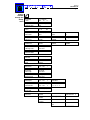
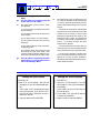
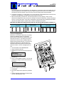
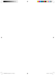
Initializing the
system
Keystrokes & Controller CommandPrompts
Self Test
Passed
User Initializing
Select Language
1-English
2-Español
3-Deutsch
4-Français
5- Italiano
6- Suomi
7- Nederlands
8- Svenska
9-Português
A-Norsk
Set Date
1-No 2-Yes
YYYY / MM / DD
1997
02
17
Set Time
1-No 2-Yes
HH : MM PM/AM
12 : 42
PM
Select Units
1-No 2-Yes
1:Inches 2:Meters
Units:1
5750-212
Revision A
Page 7
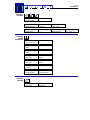
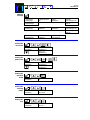
Setting
variables
through the
Set-Up
menu
Set-Up Menu
1-Date
YYYY / MM /DD
1997
02
17
Set-Up Menu
2-Expiration Date
Expiration Days
0000
Set-Up Menu
3-Time
HH : MM PM/AM
00 : 00
AM
Set-Up Menu
4-Work Shifts
Set Shifts (1-6):
Shift :1
Start:
08:00
Shift Name:
A<
Set-Up Menu
5-Item Count
Start:
0000001
End:
0009999
Change:
01
Set-Up Menu
6-Pallet Count
Items per Pallet
0000012
Start:
0000001
End
0009999
Set-Up Menu
7-Message Indent
Set Message Indent
000.5 inches
Set-Up Menu
8-Character Width
Set Character Width
4
Set-Up Menu
9-Dot Size
Dot Diameter (1-9):
4
Set-Up Menu
A-Font
1:7B 2:7 3:5
Set Font:
Set-Up Menu
B-Print Mode
Print Multiple
1-No 2-Yes
Set-Up Menu
C-Box Length
Box Length:
000.2 inches
Set-Up Menu
D-Message Gap
Message Gap:
000.4 inches
Set-Up Menu
E-Print Speed
Fixed Speed:
1-No 2-Yes
Set-Up Menu
F-Print Direction
Fixed Direction (Y/N):
1-No 2-Yes
:2
Set-Up Menu
G-Code Date
Rollover Hr (0-23):
00
Set-Up Menu
H-Password
Password
1-Enable
Password
2-Disable
Password
3-Change
:1
:2
Print Speed:
040.0 ft/min
Fixed Direction
1:<--- 2:---> :2
Password
_______________
Disabling Password...
Password
Invalid Password X
Old Password
_______________
Password
OK
New Password
______________
Confirm Password
______________
5750-212
Revision A
Page 8
Adjusting
dot sizes
Accessing
system
information
Set-Up Menu
I-Column Dot Adjus
Column Dot Adjust
0
Set-Up Menu
J-Single Dot Adjust
Dot:1
Dot Size:250
Factory Setting Y/N
1-No 2-Yes :1
Set-Up Menu
K-First Dot Adjust
1st Dot Time:000 sec
1st Dot Adjust:1
Dot Adjustment:00
Information
1-Unused Messages
Unused Messages:
96
Information
2-Date
1997 / 02 / 17
Information
3-Time
12:32:49
Information
4-Print Speed
Print Speed:
40ft/min
Information
5-Item Count
Item Count:
000000
Information
6-Version
Ver. E 1.90
Information
7-Support/Supplies
Call your
Diagraph Distributor
1-Print
2-Cancel Print
Name:DIAGRAPH
DIAGRAPH<
Printing a
message
Factory Setting Y/N
1-No 2-Yes :1
5750-212
Revision A
Page 9
Editing a
message
Setting the
item count
1-New Message
2-Edit Message
2-Edit Message
3-Delete Message
Enter Message Name
DD<
Editing...
DIAGRAPH<
1-Save:DD
2-Cancel Changes: DD
2-Cancel Changes: DD
3-Edit: DD
1-New Message
2-Edit Message
Name:DD
DIAGRAPH<
Editing...
DIAGRAPH<
1-Save:DD
2-Cancel Changes: DD
2-Cancel Changes: DD
3-Edit: DD
2-Edit Message
3-Delete Message
Name:DD
DIAGRAPH<
1-Cancel Changes:DD
2-Ok. Delete: DD
2
Editing...
DIAGRAPH<
Setting the
pallet count
2
Editing...
DIAGRAPH<
Setting the
character
width
Setting the
message
indent
Setting the
font
Editing...
DIAGRAPH{1}<
Count 1,2,3
DIAGRAPH{1}<
+
Editing...
DIAGRAPH{1}<
Pallet 10,20,30...
DIAGRAPH{1}<
2
Editing...
DIAGRAPH<
Set Character Width
6
2
Editing...
DIAGRAPH<
Set Message Indent
000.5 inches
2
Editing...
DIAGRAPH<
1:7B 2:7 3:5
Set Font: 1
5750-212
Revision A
Page 10
Placing the
time in a
message
Placing the
date in a
message
2
Editing...
DD<
Editing...
DD{13:49}<
hh:mm
DD{13:49}<
hhmm
DD{1349}<
hh:mmAM/PM
DD{13:49PM}<
hh
DD{13}<
mm
DD{49}<
AM/PM
DD{PM}<
(1:AM/2:PM)
DD{2}<
2
Editing...
DD<
Editing...
DD{02/17/97}<
MM/DD/YY
DD{02/17/97}<
DD/MM/YY
DD{17/02/97}<
YYYY
DD{1997}<
YY
DD{97}<
MON
DD{FEB}<
DD
DD{17}<
MM
DD{02}<
DDD
DD{048}<
WW
DD{07}<
M
DD{B}<
W/W
DD{G}<
5750-212
Revision A
Page 11
Placing the
date in a
message
Purging all
channels in
the system
Purging
individual
channels in
the system
Editing...
DD<
Expiration Days
0030
Hold for Long
Purge 55/100
Dot: 1
Press i to Exit
Dot: 1
Purge:
44/100
Editing...
DD{19/03/97}<
XDD/MON/YY
DD{19/MAR/97}<
XMM/DD/YY
DD{03/19/97}<
XDD/MM/YY
DD{19/03/97}<
XMON YY
DD{MON 97}<
XDD
DD{19}<
XMON
DD{MAR}<
XMM
DD{03}<
XYY
DD{97}<
XYYY
DD{1997}<
XWW
DD{11}<
XDDD
DD{078}<
XM
DD{C}<
5750-212
Revision A
Page 12
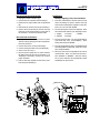
Maintenance
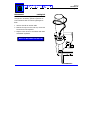
Loading Ink
Even when the can is empty, the I.V./700 has
enough ink in its delivery system to print 400 to
1000 characters after the ink low light begins to
flash.
1 Unscrew the old can and set aside.
2 Remove the cap from the new can, invert and
screw into the ink receptacle.
3 Dispose of the old can in accordance with state
and federal regulations
NOTE: DO NOT SHAKE THE INK CAN
5750-212
Revision A
Page 13
Purging All Channels
Purge the printer at the start of the workday.
1 Hold a disposable towel in front of the
printhead.
2 Press PURGE.
The printhead will expel ink for approximately
two seconds.
Continue to press PURGE if you a want a long
purge of ink.
3 Clean the face of the printhead with water.
Hold for long purge
Purge 96/100<
5750-212
Revision A
Page 14
Purging with Conditioner
Extended shutdowns of a week or more will
require purging the printhead with conditioner.
1 Remove the ink canister and attach a canister
of conditioner.
2 Hold a disposable towel in front of the
printhead.
3 Press PURGE.
4 Continue to press PURGE until the expelled fluid
is clear.
5 Remove the conditioner canister and attach
the ink canister.
5750-212
Revision A
Page 15
Purging Individual Channels
Purge a single channel when a dot is missing or
undersized.
1 Press and hold ALT and PURGE.
2 Press the corresponding numeric key to select
a channel to purge.
3 Hold a disposable towel in front of the
printhead.
4 Press PURGE.
The printhead will expel ink for approximately
two seconds.
5 Clean the face of the printhead with water.
6 Press i to exit or enter another channel to purge
and repeat steps 3 and 4.
5750-212
Revision A
Page 16
Adjusting the Screen Contrast
You can change the contrast on the LCD by
using the UP and DOWN arrows with the ALT
key.
1 Press and hold ALT and the DOWN arrow. Hold
for at least five seconds. The screen contrast
will gradually dim.
2 Press and hold ALT and the UP arrow. Hold for
at least five seconds. The screen contrast will
gradually become darker.
5750-212
Revision A
Page 17
Troubleshooting
Problems with the I.V./700 divide into three
areas: (1) the unit is not printing; (2) the unit is
printing but the results are unsatisfactory; and
(3) the unit is printing but some aspect of its
operation is unsatisfactory.
(1) Not Printing ........................................
(2) Unsatisfactory Print .............................
(3) Satisfactory Print but with Problems ......
Hardware Block Diagram ...........................
Oscilloscope Plots
2
7
18
21
25
26
5750-212
Revision A
Page 18
(1)
Not Printing, Questions and Solutions
Q1
The I.V./700 is not printing and the
power LED is not lit. Why?
S1
The printer does not have power. Check
the following:
[1] The barrel plug connection at the base
of the controller;
[2] The cable connection at the base of the
power supply;
[3] The barrel plug for a 15 VDC output;
[4] The cable connection at the rear of the
printhead;
[5] The wall receptacle to make sure that it
is supplying power.
If the printer passes all the previous tests
but still will not print, then install a new
controller board (P/N 5750-208E for European units and 5750-208A for Asian units).
Q2
The I.V./700 is not printing, the print
mode LED is on, and the photosensor
LED is not blinking. Why?
Setting the Print Speed
S2
The photosensors can not detect the product. They can be either too far from the product or dirty. Clean the photosensors and adjust the printhead to within 0.25 inch of the
product.
If cleaning the photosensor and adjusting
the position of the printhead does not fix the
problem, then put a finger in front of each
photosensor alternately and watch for the
photosensor LED to light. If a photosensor
is working, then the LED will light when you
touch it. If one does not light, the driver
board must be replaced.
If neither photosensor activates LED Q2,
remove the top cover of the printhead replace
the printhead driver board (P/N 5750-198).
You can use the defective unit while waiting for the replacement driver board by configuring the I.V./700 so that it operates in
fixed speed mode and fixed direction (see Controller directions below).
Setting the Print Direction
1 Press SET-UP.
1 Press SET-UP.
2 Press E for "E-Print Speed." The LCD will
prompt for a Yes or No to fixed speed printing.
2 Press F for "F-Print Direction." The LCD
will prompt for a Yes or No to fixed direction printing.
If you select "1-No", the display will return
to the Set-Up menu. If you select "2-Yes",
the LCD will ask for the speed in feet or
meters per minute.
If you select 1-No, the LCD will return to
the Set-Up menu.
3 Type the speed and press ENTER.
3 If you select 2-Yes, the LCD will ask you
to set the print direction.
4 Select a direction and press ENTER.
5750-212
Revision A
Page 19
Q3
The I.V./700 is not printing and the
ink LED is flashing. Why?
Q4
The I.V./700 is not printing but all LED
signals are normal. Why?
S3
The printer is out of ink. Replace the old ink
can with a new can. If the can is not empty,
replace it anyway to eliminate the possibility of a can that has lost pressure causing
the problem.
S4
Address the simplest possibility first: is the
I.V./700 in print mode? Carry out the operations described below to print a message
and verify that the printer is in print mode
and can print.
If the printer is still not printing, it is possible that the character width setting is too
small for the product line speed. To rectify
this, increase the character width by following the directions below on setting the character width.
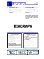
Printing a Message
1 Press PRINT and the LCD will show "1-Print"
and "2-Stop Print"
2 Press 1 and the LCD will show the name of
the last message printed and its corresponding text.
3 Scroll until "DIAGRAPH" appears as the
message to print appears on the LCD.
4 Press ENTER to print.
5 Press 2 to stop printing.
The scanned print sample above is the default DIAGRAPH message printed with controller default settings.
Character Width 1
Changing the Character
Width in a Message
1 Press EDIT.
2 Press 2. Scroll until the target message is on-screen.
3 Press ENTER.
4 Press CHARACTER WIDTH.
5 The LCD will show a range of 1 (narrow) to 9 (wide).
Select a new width by scrolling and
press ENTER.
6 Press ENTER to complete the edit
change.
Character Width 4
Character Width 6
5750-212
Revision A
Page 20
Q5
The I.V.700 is not printing even though
all of the LED's are working normally.
Q6
The I.V./700 is not printing and ALL
the LEDS are blinking. Why?
S5
Remove the four Phillips screws from the controller housing and check the cable connection between the printhead and the controller board. Check the continuity of the controller to printhead cable. If the cable is defective, replace it with cable 5750-192.
S6
A short-circuit has occurred. To determine
whether the short is in the printhead or the
controller, disconnect the barrel plug connector and the printhead connector at the
printhead.
Connect the barrel plug connector but DO
NOT connect the printhead. If the unit initializes normally, replace the printhead (P/N
5750-199). If the unit does not initialize
normally, replace the controller (P/N 5750201 for a European model and 5750-202
for an Asian model).
5750-212
Revision A
Page 21
(2) Unsatisfactory Print
The easiest way to approach any printing problem
is to reset the printer to its factory defaults and
then print the default "DIAGRAPH" message. This
simple procedure avoids all the complications of
extreme settings that interfere with the printing
process.
After the printer successfully prints "DIAGRAPH", then try each message that was
created by the customer until you find the one
with parameters (font, indent or character width)
that produced unsatisfactory printing.
Q7
All indications are normal but the I.V./
700 prints on every other box. Why?
S7
The box length distance is longer than the
length of the product. Decrease the box
length distance by following the directions
below.
Setting the Box Length
1 Press SET-UP.
2 Press C for “C-Box Length.” The display
will prompt for a distance.
3 Type in the box length in inches or centimeters.
Printing a Message
1 Press PRINT and the LCD will show "1Print" and "2-Stop Print"
2 Press 1 and the LCD will show the name
of the last message printed and its corresponding text.
3 Scroll until "DIAGRAPH" appears as the
message to print appears on the LCD.
Q8
The I.V./700 is printing normally but it's
the wrong message. Why?
S8
The wrong message has been selected to print.
Follow the directions below to print a message and select another message to print.
Q9
The I.V./700 is printing the correct message but the message is too far to one
side. Why?
S9
The message indent distance is incorrect. Adjust the distance by following the directions
below to change an individual message indent and the directions to change the default
message indent.
Setting an Individual Message
Indent
1 Press EDIT.
2 Press 2 and scroll until the target message is onscreen.
3 Press ENTER.
4 Press INDENT, move the cursor to the number for change and type in a new indent
value.
5 Press ENTER to finish.
Setting the Default Message
Indent
4 Press ENTER to print.
1 Press SET-UP.
5 Press 2 to stop printing.
2 Press INDENT.
The scanned print sample above is the
default DIAGRAPH message printed with
controller default settings.
3 Type in an indent value.
4 Press ENTER to finish.
5750-212
Revision A
Page 22
Q10 The I.V./700 is printing normally but
the message is too wide. Why?
S10
The character width is too wide or too narrow. Perform one of the following procedures:
Increase or decrease the character width by
following the directions below for changing
the character width.
If the unit is using the fixed speed feature
then increase or decrease the fixed speed by
following the directions below for changing
the fixed speed.
Q11 The I.V./700 is printing the correct message but one or more rows of ink dots
are missing from some of the characters. Why?
S11
The most likely cause is some impediment
on the faceplate that is blocking ink jet orifices. Clean the faceplate with a wipe wetted with water and purge the printhead.
Follow the purging instructions in the Maintenance section.
No Noise from the Solenoid
As you conduct the individual purge procedure, listen for the each solenoid to make a
noise. If the solenoid for the missing dot is
Changing the Character
Width in a Message
1 Press EDIT.
2 Press 2. Scroll until the target message is on-screen.
3 Press ENTER.
4 Press CHARACTER WIDTH.
5 The LCD will show a range of 1 (narrow) to 9 (wide).
Select a new width by scrolling and
press ENTER.
6 Press ENTER to complete the edit
change.
silent, you have a defective controller
board, a defective driver board or a defective solenoid.
Remove the cover of the controller and the
keypad to expose the controller board.
Check the controller board pins for the
outputs shown on sheet HBD1. If the outputs do not match those shown, replace
the controller board (P/N 5750-208E for
European models and 5750-208A for Asian
models).
If the controller board performs according
to specifications, take readings on the outputs of the printhead driver board. If the
board outputs do not match the specifications shown on HBD1 and the scope plots
at the end of this section, replace the printhead driver board (P/N 5750-198).
If the driver board performs according to
specifications, the solenoid is defective.
Replace the print module which contains
new solenoids (P/N 5750-205).
The solenoid is making noise but is not
printing.
If you hear the "whine" of a solenoid while
purging individual channels but see no ink
Setting the Print Speed
1 Press SET-UP.
2 Press E for "E-Print Speed." The LCD will
prompt for a Yes or No to fixed speed printing.
If you select "1-No", the display will return
to the Set-Up menu. If you select "2-Yes",
the LCD will ask for the speed in feet or
meters per minute.
3 Type the speed and press ENTER.
5750-212
Revision A
Page 23
coming from that channel, then the ink jet
orifice remains blocked. Remove the obstruction with a broach Kit (P/N 1902-857, shown
below).
Q12 The I.V./700 is printing the correct
message but all of the ink dots are too
small. Why?
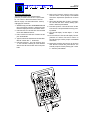
S12
5. Install the new can of ink into the controller recepticle.
6. Power ON the I.V./700 and wait for a menu
to appear.
7. Check the mulitimeter display; you should
see a value in the range of 5 to 8 volts DC.
The ink pressure is too low. Follow the procedure in this section to adjust the regulator
and the ink flow in the printhead.
8. Lift the lock ring on the regulator and
slowly turn the adjustment knob counterclockwise. The vol-tage reading should decrease
as you turn the knob.
You will need a Phillips screwdriver, a multimeter and a fresh can of ink (5750-085) for
this adjustment. Disconnect the power before starting.
9. Turn the knob counterclockwise until it
stops and shuts off the ink flow. The multimeter should show zero volts.
1. Remove the printhead cover to access test
points on the printhead driver board.
10. Place absorbent material or a container
in front of the printhead and purge until the
ink low lamp flashes.
2. Attach the black lead from the multimeter
to the bare wire (pin 16, [A]) of the cable
connecting the CPU board to the driver board
(see diagram below).
3. Attach the red lead of the multimeter to
test point 3 (TP3, [B]) on the driver board.
4. Set the mulitmeter to DC voltage.
11. Turn the regulator knob slowly clockwise and
watch the voltage increase on the multimeter.
12. Stop turning the knob when the multimeter reads 7.0 volts.
13. Press the regulator locking-ring back into
place; disconnect power and the multimeter
leads; and replace the printhead cover.
[8]
[A]
[B]
[13]
5750-212
Revision A
Page 24
Q13 The I.V./700 is printing the correct message but the characters are out of position and there are a lot of extra dots.
Why?
S13
The printhead is too far from the product
(see the scanned sample at right below). Adjust the printhead until it is closer to the box.
The faster the box travels, the closer the printhead must be to the box.
Q14 After sitting idle for a few minutes, the
first dots printed in the message are
too small when the I.V./700 starts
printing again. Why?
S14
Undersized dots on startup can result from
two adjustments: dot size and first dot. These
variables need to be tested and set at the
same time to achieve a satisfactory solution.
Adjust the size of the first printed dots by
following the directions below.
Q14 I selected fixed speed and now my I.V./
700 prints backwards or random dots.
Why?
S14
The I.V./700 print direction is wrong. Change
the print direction by following the directions
below.
Q15 The I.V./700 is printing dots of different sizes. Why?
S15
First, verify that the dot sizes identified on the
label on the bottom of the printhead match
those programmed into the unit, if not, change
them per the instructions below. If they do
match, you may have to increase or decrease
some settings to get the desired dot size.
First Dot Adjustment
1 Press and hold ALT + INFORMATION.
2 Plug in the barrel connector.
3 Release the keys when the LCD shows “Information”.
4 Press SET-UP.
5 Press K. The LCD will prompt for the number of seconds that the printer will stand
idle.
6 Type in the amount of time and press
ENTER.
7 The first line of the LCD will show “1st Dot
Adjust:1” for the first valve (dot) at the top
of the printhead.
The second line of the LCD will prompt for
“Dot Adjustment”. If the first printed dot
was small in the sample print, increase the
value by 10 which will increase the size of
the first printed dot by valve 1.
If the first printed dot by valve 1 was fullsized, DO NOT enter a new value: leave
the existing value and press ENTER.
8 The LCD will change to “1st Dot Adjust:2”
for valve 2. Repeat this process for all
valves.
9 After the seventh dot, press SET-UP. The
LCD will prompt for “Factory Setting”. Select “2-Yes”. Wait the time designated in
step 5 and make a print sample. If it is
satisfactory, this procedure is complete. If
the sample is not satisfactory, unplug the
barrel connector and repeat this procedure.
Setting the Print Direction
1 Press SET-UP.
2 Press F for "F-Print Direction." The LCD
will prompt for a Yes or No to fixed direction printing.
If you select 1-No, the LCD will return to
the Set-Up menu.
3 If you select 2-Yes, the LCD will ask you
to set the print direction.
4 Select a direction and press ENTER.
Changing All Printed Dot Sizes
1 Press SET-UP.
2 Press DOT SIZE. The LCD will prompt for
a dot diameter.
3 Scroll to a new dot diameter and press
ENTER.
Run some print samples with the new
dot diameter to see if the printing is improved. If not, change the dot diameter
again and run more print samples.
5750-212
Revision A
Page 25
(3) Satisfactory Print with
Other Problems
Q18 I'm running the I.V./700 eight hours per
day and have to replace the ink can every other day. Is this normal?
This section covers problems that do not cause the
printer to stop printing nor produce unsatisfactory
prints. These situations are warnings that more
serious problems might be on the way.
Q15 Shouldn't I shake the ink can before I
install it in the printer? I always have
to shake paint cans.
S18
S15
No. Never shake a can of Diagraph ink. The ink
in the can is actually in a bag that is attached to
the fitting at the top of the can. The can has
been pressurized with air that pushes against the
sides of the bag and forces ink through the fitting. If vigorously shaken, the bag can tear loose
and ink will not flow from the can.
Q16 Do I need to cover my I.V./700 printer
during a washdown?
S16
Yes.
Q17 I've noticed ink accumulating on the
faceplate. Is this normal?
S17
Yes. Over the course of an 8-hour shift enough
ink may accumulate to form a hanging drop.
This ink may allow environmental debris to
accumulate, which is why the frontplate
should be wiped after at the beginning and
end of each shift.
Perhaps. Each can of ink will print approximately 225,000 characters. Actual usage varies depending upon operating conditions.
Q19 I see ink in the receptacle for the ink can
when I install a new can. Is this normal?
S19
Yes. A few drops of ink may accumulate each
time the ink can is changed, eventually building up if not cleaned away.
Q20 Ink is leaking from the fitting where the
ink line attaches to the controller. What
should I do?
S20
Replace the lower enclosure assembly of the
controller (P/N 5750-207).
Q21 Ink is leaking from the fitting on the pigtail from the printhead? Is this normal?
S21
No. Replace the fittings. Use P/N 5750-214
for the female and 5750-213 for the male.
Q22 What parts should I expect to replace
after a year of 8-hour-per-day usage?
S22
None in a normal environment. Generally, the
first thing to fail is the printhead, which lasts
over a year.
5750-212
Revision A
Page 26
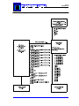
Hardware Block Diagram
HBD1
5750-212
Revision A
Page 27
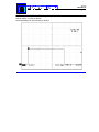
Oscilloscope Plot of Driver Board 15 V Output
Veritcal Setting: 5.0 VDC per division
Horizontal Setting: 50 microseconds per division
5750-212
Revision A
Page 28
Oscilloscope Plot of CPU Board 5 V Output
Veritcal Setting: 2.0 VDC per division
Horizontal Setting: 50 microseconds per division
5750-212
Revision A
Page 29
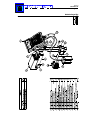
Parts Drawings
General Assembly ..................................... 30
Controller Assembly .................................. 31
Printhead Assembly .................................. 32
5750-212
Revision A
Page 30
Modular Parts Kits
5750-212
Revision A
Page 31
Controller Assembly
5750-212
Revision A
Page 32
Printhead Assembly
5750-212
Revision A
Page 33
Test Results
Declaration of Conformity .......................... 34
Inchscape Testing Services ........................ 35
5750-212
Revision A
Page 34
5750-212
Revision A
Page 35
5750-212
Revision A
Page 36
Appendix A
5750-199N
5750-201N
5750-113N
5750-125N
5750-117N
5750-183N
1902-857N
Service Parts Instructions
Modular Printhead ..................... 37
Controller ................................. 41
Power Supply ........................... 44
Tubing Kit ................................. 45
& 118N Firmware ...................... 46
External Photosensor ................. 48
Broach Kit ................................ 50
5750-212
Revision A
Page 37
I . V . / 7 0 0
Modular Printhead
Contents
1 I.V./700 Printhead
1 Installation Instructions
Materials Required
Clean Wipes
Specifications
Resolution: 7 dots veritcal, 12 dots/inch horizontal (4.8 dots/cm)
Dot Diameter Range: 0.100 inch to 0.125 inch
(2.54 mm to 3.175 mm)
Recommended Throw Distance: 0.25 in. max
(6.35mm)
Max. Line Speed: 250 ft/min (76.2 m/min)
Photosensors:Two photosensors to measure speed
and direction.
Operating Pressure: 7psig-9 psig
Character Height: .50 in (12.7 mm) 7-dot font
.36 in. (9 mm) 5-dot font
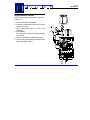
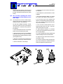
Printhead Installation
Before starting the installation, note the label on
the bottom of the printhead. This label shows
the optimal adjustments for printhead variables at
the time of manufacture. Each printhead is
unique and requires individual adjustments for
optimal printing. Copy these values so you can
enter them into the controller. At right is an
example of the label. DO NOT USE THE VALUES
IN THIS SAMPLE LABEL. Use the values on the
label on your printhead.
1 Secure the printhead in its bracket with the fourprong knobs at [A].
2 Connect the ink line from the I.V./700 controller to the ink fitting at [B].
3 Connect the signal cable from the I.V./700 controller to the printhead at [C].
4 Insert the ink can and power up the controller.
5 Place a clean wipe against the faceplate and press
PURGE.
Printhead Settings
1 Simultaneously press ALT and INFORMATION and
plug in the barrel connector. Release the keys
when the display shows the information menu.
2 Press SET-UP. The LCD will show the extended
menu with additional choices.
3 Press I and the LCD will show "Column Dot Adjust:" Press ENTER.
5 7 5 0 - 1 9 9 N
5750-212
Revision A
Page 38
4 Type the value from the bottom of the label identified as "Column Dot =". Press Enter.
5 Press SET-UP then J. The LCD will show "Dot:
1". The controller is waiting for a dot diameter
value for the dot from the first valve in the printhead.
6 Refer to the "Dot Size" value for valve 1 on the
printhead label and enter it at the prompt. Press
ENTER when done. Repeat this operation for all
seven valves.
7 After typing the label value for dot 7, press SETUP. The LCD will show "Factory Setting Y/N?"
Select 2-YES.
8 Press Set-Up then K. The LCD will show "1st Dot
Time:000 sec" Accept this default time by pressing ENTER. If the controller shows value other
than zero, change that value to zero and press
ENTER.
9 The LCD will display "1st Dot Adjust.: 1." Press
ENTER.
10 The second line of the LCD will display "Dot
Adjustment: 00". Refer to "1st Dot" for valve 1
on the printhead label and type it at the prompt.
Press ENTER when done.
11 Repeat the procedure from steps 7 and 8 for all
seven dots. After the seventh dot, press SET-UP.
The LCD will prompt for "Factory Setting Y/N".
Select 2 = YES.
Printing Problems
Do not make any adjustments described in this
section until you have eliminated incorrect settings
on the controller as a probable source of the
problem.
One or more of the printed dots is consistently too small.
Single Dot Diameter Adjustment
This function allows you to change the dot
diameter of individual dots by altering the stroke,
in microseconds, of a piston in an ink channel.
1 Press and hold ALT+INFORMATION.
2 Plug in the barrel connector.
3 Release the keys when the LCD shows "Information."
Information
1-Unused Messages
4 Press SET-UP
Dot #4 reduced by 25
Dot #4 at preset value
Dot #4 increased by 40
5750-212
Revision A
Page 39
5 Press J on the QWERTY keypad. The LCD will prompt for the number of the dot that is not printing like
the other dots. The top dot on the printhead is dot number 1 and the bottom dot is dot number 7.
6 Scroll to the number of the problem dot.
7 Press ENTER.
8 The LCD will prompt for a new diameter of the selected dot. Move to the second digit (250) and scroll
to a new value. The scroll changes by units of 10.
9 Press SET-UP. The LCD will ask if you want to keep the "Factory Setting Y/N?" Select "1-NO." When you
select NO, the I.V./700 remembers the new dot diameter value only until the next initialization.
By running print samples and altering the diameter of a single dot, you can make that single dot match
the appearance of the other dots.
10 When you achieve the best print, select "2-YES" when exiting this function. This choice makes the new
pulse width value permanent.
Small Dot #4
Dot #4 adjusted correctly
After sitting idle for several minutes, the
initial prints have dots that are too small.
First Dot Adjustment
This procedure allows you to overcome this problem
by independently increasing dot sizes exclusively on
the first print. Second and all subsequent prints return
to their defined dot-size settings.
1 Press and hold ALT+INFORMATION.
2 Plug in the barrel connector.
3 Release the keys when the LCD shows "Information."
Information
1-Unused Messages
4 Press SET-UP
5 Press K on the QWERTY keypad. The LCD will
prompt for the time in seconds that the printer
will stand idle."
1st dot time:000 sec
6 Type in the amount of time and press ENTER.
7 The LCD will show "1st Dot Adjust:1" for the
first valve (dot) at the top of the printhead. Press
ENTER.
1st dot adjust:1
Dot Adjustment:30
Dot #4 oversized
5750-212
Revision A
Page 40
The second line of the LCD will prompt for "Dot Adjustment." If this dot is small in the sample print (see
the first sample below), increase the value by 10 which increases the size of the dot for the first print.
If the dot was full-size, DO NOT enter a new value: leave the existing value and press ENTER
8 The display will change to "1st Dot Adjust:2" for the second valve. Press ENTER and the second line will
prompt for "Dot Adjustment." Repeat this process through all seven dots.
9 After the seventh dot, press SET-UP. The LCD will prompt for "Factory Setting." Select "2-YES."
Wait the time designated in step 5, then print a message. If the print is satisfactory, unplug and replug to
set the I.V./700 in print mode. If the print is unsatisfactory reset the first dot by repeating this procedure
(C8) and run another sample. Repeat until you achieve a satisfactory first print.
Noticeable size differences between dots printed in rows (Ö) and dots printed in columns (×)
Dots with column adjustment
set too low
Nominal Letters
Column Dot Adjustment
When the I.V./700 prints a single dot, the printing
channel has individual access to ink pressure.
When all seven channels print simultaneously, they
share the ink pressure. This sharing can produce
printed dots in columns that are slightly smaller in
diameter than single printed dots. The column dot
adjustment enables you to eliminate slight size
variances between dots printed in rows and dots
printed in columns. Start by unplugging the I.V./
700.
1 Press and hold ALT and INFORMATION.
2 Plug in the barrel connector.
3 Release the keys when the LCD shows "Information."
Information
1-Unused Messages
4 Press SET-UP
5 Press I on the QWERTY keypad. The LCD will
prompt for a change in value of the column dot
adjustment:
Column Dot Adjust:
3
6 Scroll to a higher or lower number.
7 Press ENTER.
8 Run a print sample at the speed of a production
run.
9 Continue adjusting until the dots in columns match
the size of dots printed in rows.
Dots with column adjustment
set too high
5750-212
Revision A
Page 41
I.V./700
Controller
Contents
1 Controller Assembly
1 Instruction set
Record the Printhead Settings
Replacing the controller will eliminate all message
formats and printhead values. Use the chart at
right to record the column dot value and the
settings for single dot diameters and first dot
values. If the old controller is inoperable, skip to
the next section, "Disconnecting the Old Controller", and use the label on the bottom of the
printhead. Start by unplugging the controller.
1 Simultaneously press ALT and INFORMATION and
reconnect the power. Release the keys when the
LCD shows the information menu.
2 Press SET-UP. The LCD will show the beginning
of the Set-Up menu. Press I. The LCD will display "Column Dot Adjust:".
3 Record the value shown in the second line of
LCD under "Column Dot Adjust:". Press ENTER.
4 Press SET-UP then J. The LCD will show "Dot:
1". Press ENTER.
5 7 5 0 - 2 0 1 N
Materials Required
Clean wipes
5 Record the value shown after "Dot Size" on the
LCD in the Valve 1 row in the chart at right. Repeat this operation for all seven dots.
6 After the seventh dot, press SET-UP. The LCD will
respond with "Factory Setting Y/N?" Press ENTER.
7 Press Set-Up then K. The LCD will show "First
Dot Time" and a number of seconds. Record the
number of seconds in the chart at right and press
ENTER.
8 The screen will display "1st Dot Adjust.: 1" for
the first valve (dot) at the top of the printhead.
The second line of the LCD will show a value for
"Dot Adjustment." Record this value in the "1st
Dot" column below and press ENTER to scroll
through each of the seven first dot settings.
9 After the seventh dot, press SET-UP. The LCD
will respond with “Factory Setting Y/N?”. Press
ENTER.
5750-212
Revision A
Page 42
Disconnecting the Old Controller
1 Unplug the barrel connector [A].
Initialization
2 Unscrew the ink container and set aside [C].
3 Disconnect the signal cable from the printhead
[B].
1 Press and hold both ALT and the left arrow key
while connecting the power. Release the keys
when "Erase all messages?" appears on the LCD.
Press 1 for "No" and then ENTER.
4 Disconnect the ink line from the printhead [D].
5 Remove the 4-prong knob [E] and the carriage
bolt from the mounting bracket on the back of
the controller. Set the old controller aside.
New Controller Installation
1 Unwrap the new controller and secure in place
with the 4-prong knob [E] and the carriage bolt
previously removed.
2 Connect the ink line to the printhead [D].
3 Connect the signal cable to the printhead [B].
4 Screw in the ink can [C].
5 Plug the power supply into an outlet and then
the barrel connector [A] into the controller. The
"Diagraph Corporation" prompt will confirm
proper operation.
6 Press a clean wipe against the face of the printhead and press PURGE [F].
Setting Language, Time, Date and Units
2 The LCD will request a choice of language. Enter
the number that matches your language choice:
1 English
3 Deutsch
2 Español
4 Français
5 Italiano
3 The next choice is Date. The LCD will prompt for
year-month-day entry (YYYY/MM/DD). Enter
today's date and press ENTER.
4 The LCD will prompt for time in an HH:MM format
and a designation of AM or PM. Enter the current
time and press ENTER.
5 After time, the screen will prompt for the units of
measurement. Enter Y to select and choose either "INCHES" or "METERS." After this choice,
the I.V./700 controller will automatically reboot
and display the print screen.
5750-212
Revision A
Page 43
Printhead Adjustments
The next instructions cover transferring the
previously recorded values to the I.V./700 controller. The "chart" in these instructions is the one
filled in on page 1 of these instructions. Start by
unplugging the controller.
1 Simultaneously press ALT and INFORMATION and
plug in the barrel connector. Release the keys
when the display shows the information menu.
2 Press SET-UP. The LCD will show the extended
menu with additional choices.
3 Press I and the LCD will show "Column Dot Adjust:" Press ENTER.
4 Type the value from the bottom of the chart identified as "Column Dot =". Press Enter.
5 Press SET-UP then J. The LCD will show "Dot:
1". The controller is waiting for a dot diameter
value for the dot from the first valve in the printhead.
6 Refer to the "Dot Size" value for valve 1 on the
chart and enter it at the prompt. Press ENTER
when done. Repeat this operation for all seven
valves.
7 After typing the label value for dot 7, press SETUP. The LCD will show "Factory Setting Y/N?"
Select 2-YES then press ENTER.
8 Press Set-Up then K. The LCD will show "1st Dot
Time:000 sec" Accept this default time by pressing ENTER.
9 The LCD will display "1st Dot Adjust.: 1." Press
ENTER.
10 The second line of the LCD will display "Dot Adjustment: 00". Refer to "1st Dot" for valve 1 on
the chart and type it at the prompt. Press ENTER
when done.
11 Repeat the procedure from step 10 for all seven
dots. After the seventh dot, press SET-UP. The
LCD will prompt for "Factory Setting Y/N". Select
2 = YES then press ENTER.
5750-212
Revision A
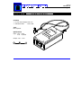
Page 44
I.V./700
Power Supply
Contents
1 I.V./700 Power Supply 5750-113
1 Instruction Sheet
5750-113N
Tools
None required.
Specifications
Input: 100V - 240V
0.7A 50/60Hz
Output: 1.5V - 2.0A
+
-
5 7 5 0 - 1 1 3 N
5750-212
Revision A
Page 45
I.V./700
[B]
Tubing Kit
[C]
5 7 5 0 - 1 2 5 N
Typical Installation
This tubing kit enables you to replace a damaged
ink line segment between an I.V./700 controller
and an I.V./700 printhead. The illustration above
shows a typical installation.
Installation Notes
_Unscrew the ink can from the controller and set
aside before starting the ink line replacement.
_Before cutting away damaged tubing, depress the
nipple end of the original male quick-disconnect
fitting to bleed ink from the tubing.
[C]
Warning: This ink pressure can be up to
90 PSIG (6.2 Bar). Exercise Caution!
[D]
Contents
1 Quick-Disconnect Female Inline Fitting [F] 5750-214
2 Quick-Disconnect Male Fitting [C] & [G] 5750-213
1 Tubing, 0.25-inch OD, 24 inches [D]
Tools & Materials
Utility Knife & Clean Wipes
Safety Goggles
_Wrap a clean wipe around the original ink line
before cutting to absorb spilled ink.
_Use a sharp blade such as a single-sided razor
blade, utility knife or diagonal side cutters to make
a clean cut in the replacement tubing. Avoid
crimping the tubing when cutting.
_Loosen the nut on the fitting. Slip the tubing
over the barbed end of the fitting. Tighten the nut
until it comes to a stop.
_Exercise caution when pressurizing the tubing for
the first time.
[A] Original ink line.
[B] Replacement female quick-disconnect fitting.
[C] Replacement male quick-disconnect fitting.
[A]
[A]
[B]
[C]
[D]
[B]
[C]
[D] Replacement ink line cut to desired length
from the 24 inches of tubing provided in
this kit.
5750-212
Revision A
Page 46
I.V./700
Firmware
5 7 5 0 - 1 1 7 N & 1 1 8 N
WARNING: ESD SENSITIVE DEVICE. OBSERVE PRECAUTIONS.
Use anti-static protection throughout these procedures. Follow the directions included with
disposable wrist strap.
Record the Printhead Settings
Replacing the firmware (chips U3 and U4) will
eliminate all message formats and printhead values.
Use the chart above to record the column dot value
and the settings for single dot diameters and first
dot values.
1 Simultaneously press ALT and INFORMATION and
reconnect the power. Release the keys when the
LCD shows the information menu.
2 Press SET-UP. The LCD will show the beginning of
the Set-Up menu. Press I. The LCD will display
"Column Dot Adjust:".
3 Record the value shown in the second line of LCD
under "Column Dot Adjust:". Press ENTER.
4 Press SET-UP then J. The LCD will show "Dot: 1".
Press ENTER.
5 Record the value shown after "Dot Size" on the
LCD in the Valve 1 row in the chart below. Repeat
this operation for all seven dots.
6 After the seventh dot, press SET-UP. The LCD will
respond with "Factory Setting Y/N?" Press ENTER.
7 Press Set-Up then K. The LCD will show "First Dot
Time" and a number of seconds. Record the number
of seconds in the chart above and press ENTER. This
setting is usually 000.
8 The screen will display "1st Dot Adjust.: 1" for the
first valve (dot) at the top of the printhead. The
second line of the LCD will show a value for "Dot
Adjustment." Record this value in the "1st Dot"
column at right and press ENTER.
9 The LCD will change to "1st Dot Adjust.: 2." Repeat the process in step 8 until all the values for
first dot are recorded in the chart.
10 After the seventh dot, press SET-UP. The LCD will
respond with “Factory Setting Y/N?” Press ENTER.
Removing the Old Chips
1 Disconnect power by unplugging the barrel connector from the base of the controller.
2 Unscrew the ink canister and set aside.
3 Unscrew the four Phillips screws at the corners of
the controller and remove the top cover. Set aside
the cover and the screws.
4 Remove the keypad assembly by prying up at the
pin strip connectors on each side of the keypad
board with a small screwdriver. Set aside the keypad assembly.
5 Remove chips U4 and U3 by pressing on the clips
at the top and bottom of the DIP sockets.
6 Set aside chips for RGA return.
5750-212
Revision A
Page 47
Installing the New Chips
1 Remove the chip set from the foam packing and
match labels of "U3" and "U4" with the chip sockets on the controller board.
2 Orient chips with the notches at the top-towards
the LCD screen. Ensure that no pins are bent.
3 Carefully align pins and firmly push each chip
into its socket. DIP socket clips will snap into
place when the chips are seated correctly.
4 Replace the keypad assembly by matching and
pressing into place the pin strip connectors on
each side of the keypad board.
5 Replace the top cover and secure in place with
the four Phillips screws removed earlier.
Initialization
Setting Language, Time, Date and Units
The first time you plug in the I.V./700 with new
firmware, you must select the language, time, date
and unit of measure.
1 Plug in the barrel connector.
2 The LCD will request a choice of language. Enter the number that matches your language
choice:
1 English
3 Deutsch
5 Italiano
2 Español
4 Français
3 The next choice is Date. The LCD will prompt for
year-month-day entry (YYYY/MM/DD). Enter
today's date and press ENTER.
4 The LCD will prompt for time in an HH:MM format and a designation of AM or PM. Enter the
current time and press ENTER.
5 After time, the LCD will prompt for the units of
measurement. Enter Y to select and choose either "INCHES" or "METERS." After this choice,
the I.V./700 controller will change to the print
message screen.
Printhead Adjustments
The next instructions cover transferring the
previously recorded values to the I.V./700 controller. The "chart" in these instructions is the one
filled in on page 1 of these instructions. Start by
unplugging the controller.
1 Simultaneously press ALT and INFORMATION and
plug in the barrel connector. Release the keys
when the display shows the information menu.
2 Press SET-UP. The LCD will show the extended
menu with additional choices.
3 Press I and the LCD will show "Column Dot Adjust:" Press ENTER.
4 Type the value from the bottom of the chart identified as "Column Dot =". Press Enter.
5 Press SET-UP then J. The LCD will show "Dot: 1".
The controller is waiting for a dot diameter value
for the dot from the first valve in the printhead.
6 Refer to the "Dot Size" value for valve 1 on the
chart and enter it at the prompt. Press ENTER
when done. Repeat this operation for all seven
valves.
7 After typing the label value for dot 7, press SETUP. The LCD will show "Factory Setting Y/N?"
Select 2-YES.
8 Press Set-Up then K. The LCD will show "1st Dot
Time:000 sec" Accept this default time by pressing ENTER.
9 The LCD will display "1st Dot Adjust.: 1."
10 The second line of the LCD will display "Dot Adjustment: 00". Refer to "1st Dot" for valve 1 on
the chart and type it at the prompt. Press ENTER
when done.
11 Repeat the procedure from step 10 for all seven
dots. After the seventh dot, press SET-UP. The
LCD will prompt for "Factory Setting Y/N". Select
2 = YES.
5750-212
Revision A
Page 48
I.V./700
External Photosensor
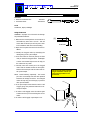
These instructions cover the configuration
of the I.V./700 ink jet printer with the
external photosensor.
Contents
External Photosensor [1] and bracket [2]
5750-113
Photosensor/Controller Cable [3]
5750-182
Instruction Sheet
5750-183N
Configuration
See the diagram on page 2 for the
configuration command sequence.
Note dimension "X" in the illustration at
right--the distance from the center of the
photosensor to the center of the printhead.
When mounting the photosensor, make
sure that the X dimension is less than the
gap between the products as they move by
on the conveyor. If X is greater than the
gap between products, some products will
missed when the I.V./700 is printing.
Measure X and use it to set Message
Indent in the controller. With an external
photosensor, the indent distance is the sum
5750-183N
5750-212
Revision A
Page 49
of the distance from the edge of the product to
the first printed character plus the distance from
center-to-center of the photosensor and the
printhead. For example, if you wanted the
message to be printed 2 inches from the leading
edge of the product and the X dimension is 10
inches, then the indent setting is 12 inches. See
the User's Manual on setting the message indent.
Setting the controller for the external photosensor requires accessing a menu that is available
only after a special initialization. DO NOT USE
THIS MENU option if you are using the standard
I.V./700 and its built-in photosensors. Start by
unplugging the I.V./700
4 Press SET-UP.
5 Press L on the QWERTY keypad. The LCD will
prompt for an external photocell.
1 Press and hold ALT and INFORMATION.
7 Type in a print speed and press ENTER. The LCD
will prompt for a fixed print direction.
2 Plug in the barrel connector.
3 Release the keys when the LCD shows "Information".
Information
1-Unused Messages
External Photocell?
1-No
2-Yes :1
6 Press 2 and then ENTER. The LCD will prompt
for a fixed print speed.
Print Speed:
040.0 ft/min
Fixed Direction:
1:<--- 2: ---> :2
8 Select the print direction and press ENTER.
4 1
6
2
1
4
5
L
5750-212
Revision A
Page 50
I.V./700
Contents
1 Broach & Cardboard Tube
1 Instruction Sheet
Broach Kit
1902-857N
1902-857
1902-857N
Tools
Conditioner, Wipes, Flashlight
Using the Broach
WARNING: Improper use of a broach can damage
the printhead membrane.
1. Make sure the broach pin does not extend out of
the handle any more than 0.10 inch. This will
ensure that the broach pin will not poke a hole
in the membrane and cause internal leaking.
2. Wipe the front plate clean with a cloth and conditioner.
3. Identify the clogged orifice by identifying the
missing dot(s) from a print sample.
[1]
0.10 inch
[3]
4. Count the orifices on the front plate up or down
until you locate the clogged orifice. A flashlight
or other concentrated light source will help, as
the orifices are very small.
5. Carefully insert the broach pin in the clogged
orifice until the handle touches the front plate.
Remove the broach pin from the orifice and create a print sample.
NOTE: Avoid broaching repeatedly. The broach
pin is like a microscopic file that with repeated
insertions will enlarge the orifice. The enlarged
orifice will seep ink, print off target, or produce
other print anomalies.
6. If the print sample shows that the orifice is still
clogged, purge the printhead and make a second print sample.
7. If orifice is still clogged, count the orifices again
to make sure that you are broaching the correct
orifice.
8. If orifice is still clogged, repeat steps 5 to 6.
This broach kit works with both
single and double column (as
shown below) models of I.V.
printheads.