1
Brother Color Laser Printer
HL-2600CN Series
User’s Guide
Version 0
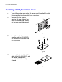
Before you can use the printer, you must set up the hardware and install the driver. Please set up the printer while referring to the Quick
Setup Guide.
Please read this manual thoroughly before using the printer and keep the CD-ROM in a convenient place for quick and easy reference
at all times.
Please visit our user support web site, Brother Solutions Center, at http://solutions.brother.com. You can download driver updates
and product information.
Trademarks
Brother is a registered trademark of Brother Industries, Ltd.
Apple, the Apple Logo, and Macintosh are registered trademarks in the United States and other
countries, and True Type is a trademark of Apple Computer, Inc.
Centronics is a trademark of Genicom Corporation.
EPSON is a registered trademark, and FX-850 and FX-80 are trademarks of Seiko Epson Corporation.
Hewlett Packard, HP, PCL5C, PCL 5e, PCL 6 and PCL are registered trademarks, and HP LaserJet 5,
HP LaserJet 4+, HP LaserJet Plus, HP LaserJet II, HP LaserJet IID, HP LaserJet IIID, HP-GL, HPGL/2, and Bi-Tronics are trademarks of Hewlett-Packard Company.
IBM, Proprinter XL, Proprinter, and IBM/PC are registered trademarks of International Business
Machines Corporation.
Intellifont is a registered trademark of AGFA Corporation, a division of Miles, Inc.
Microsoft and MS-DOS are registered trademarks of Microsoft Corporation.
Windows is a registered trademark of Microsoft Corporation in the United States and other countries.
PostScript is a registered trademark of Adobe Systems Incorporated.
This printer contains UFST and Micro Type from Agfa Division.
PANTONE Colors generated by the HL-2600CN are four- and /or three-color process simulations and
may not match PANTONE-identified solid color standards. Use current PANTONE Color Reference
Manuals for accurate color.
PANTONE Color simulations are only obtainable on this product when driven by qualified Pantonelicensed software packages. Contact Pantone Inc. for a current list of qualified licensees.
All trademarks noted herein are either the property of Brother Industries, Ltd., PANTONE® and other
Pantone, Inc. trademarks are the property of Pantone, Inc. ©Pantone, Inc., 1988
ENERGY STAR is a U.S. registered mark.
All other brand and product names mentioned in this user’s guide are registered trademarks or
trademarks of respective companies.
Compilation and Publication
Under the supervision of Brother Industries Ltd., this manual has been compiled and published,
covering the latest product descriptions and specifications.
The contents of this manual and the specifications of this product are subject to change without notice.
Brother reserves the right to make changes without notice in the specifications and materials contained
herein and shall not be responsible for any damages (including consequential) caused by reliance on
the materials presented, including but not limited to typographical and other errors relating to the
publication.
©2001 Brother Industries Ltd.
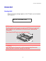
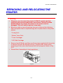
Shipment of the Printer
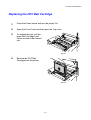
If for any reason you must ship your Printer, carefully package the Printer to avoid any damage during transit.
It is recommended that you save and use the original packaging. The Printer should also be adequately
insured with the carrier.
WARNING
When shipping the Printer, the TONER CARTRIDGES and ALL CONSUMABLES must be removed from the
Printer. Failure to remove the CONSUMABLE ITEMS during shipping will cause severe damage to the
Printer and will VOID THE WARRANTY.
B
Brrootthheerr LLaasseerr PPrriinntteerr
HL-2600CN Series
User’s Guide
(For USA & CANADA Only)
For technical and operational assistance, please call:
In USA
1-800-276-7746
In CANADA
1-800-853-6660
514-685-6464 (within Montreal)
If you have comments or suggestions, please write us at:
In USA
In CANADA
Printer Customer Support
Brother International Corporation
15 Musick
Irvine, CA 92618
Brother International Corporation (Canada), Ltd.
- Marketing Dept.
1, rue Hôtel de Ville
Dollard-des-Ormeaux, PQ, Canada H9B 3H6
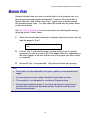
FAX-BACK SYSTEM
Brother Customer Service has installed an easy to use Fax-Back System so you can get instant answers to common technical
questions and product information for all Brother products. This is available 24 hours a day, 7 days a week. You can use the
system to send the information to any fax machine, not just the one you are calling from.
Please call 1-800-521-2846 (USA) or 1-800-681-9838 (Canada) and follow the voice prompts to receive faxed instructions on
how to use the system and your index of Fax-Back subjects.
DEALERS/SERVICE CENTERS (USA only)
For the name of an authorized dealer or service center, call 1-800-284-4357.
SERVICE CENTERS (Canada only)
For service center addresses in Canada, call 1-800-853-6660
INTERNET ADDRESS
Brother Global Web Site: http://www.brother.com
For Frequently Asked Questions (FAQs), Product Support and Technical Questions, and Driver Updates:
http://solutions.brother.com
(USA Only) For Brother Accessories & Supplies: http://www.brothermall.com
i
DEEFFIINNIITTIIO
ON
NS
SO
OFF WA
AR
RN
NIIN
NG
GS
S, CA
AU
UTTIIO
ON
NS
S, A
AN
ND
D NO
OTTE
ES
S
The following conventions are used in this User’s guide:
! Warning
Indicates warnings that must be observed to prevent possible personal
injury.
! Caution
Indicates cautions that must be observed to use the printer properly or
prevent damage to the printer.
Note
Indicates notes and useful tips to remember when using the printer.
TO
O US
SE
RIIN
AFFE
E TTH
NTTE
ELLY
HE
ER
Y
E PR
R SA
! Warning
This printer is heavy and weighs approximately 39kg (86lbs). When
you move or lift this printer, be sure at least 2 people lift it together.
! Warning
The Fusing Unit becomes extremely HOT during operation. Wait until it
has cooled down sufficiently before replacing consumables.
ii
! Warning
If the printer becomes hot, blows smoke, or generates obscure odor,
turn the printer off immediately and unplug the printer. Contact your
dealer.
! Warning
If metal objects, water or other liquids get inside the printer, turn the
printer off immediately and unplug the printer. Contact your dealer.
! Warning
Do not put consumables such as the Toner Cartridges and the Waste
Toner Pack into a fire. Some consumables can be flammable under
certain conditions.
! Warning
Do not look directly at the laser beam light. It might cause damage to
your eyesight. Do not remove or break open the printer’s safety
interlocks.
! Warning
Do not run the printer with the Top Cover, Front Cover and Rear Access
Covers open and the interlocks removed.
! Warning
Turn off the printer before replacing consumables.
! Warning
Do not place any items on the printer.
! Warning
In case of a fuser oil spill, you must clean it up immediately. Contact
your dealer.
iii
PRRIINNTTEERR DO
O'S
SA
AN
ND
D DO
ON
N'TTS
S FFO
OR
R OP
PTTIIM
MU
UM
M PR
RIIN
NTT QU
UA
ALLIITTY
Y
! Caution
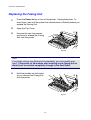
Before you move or lift the printer, remove the Toner Cartridges, Waste
Toner Pack, Oil Bottle and Fusing Unit to avoid spills. Be sure to keep the
printer as level as possible. Damage caused by failure to remove the
supplies will void your warranty.
! Caution
Do not touch the rollers of the Fusing Unit. This can degrade print quality.
iv
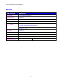
TABLE OF CONTENTS
TABLE OF CONTENTS
CHAPTER 1 INTRODUCTION
ABOUT THIS User’s Guide
1-1
ABOUT THIS PRINTER
Checking the Carton Components
General View
Features
Options
RAM
Operating and Storage Environment
1-3
1-3
1-5
1-6
1-12
1-13
1-13
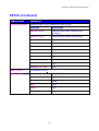
CHAPTER 2 DRIVER AND SOFTWARE
Printer Driver
Features in the PCL Printer Driver (Windows 95/98/Me Users Only)
Features in the PS printer driver (Windows 95/98/Me users only)
Software for networks
Software for Windows Computers
Software for Macintosh Computer
2-1
2-2
2-10
2-15
2-17
2-18
Printer Settings
Factory Settings
2-21
2-21
v
TABLE OF CONTENTS
CHAPTER 3 BEFORE WORKING WITH THE PRINTER
AUTOMATIC EMULATION SELECTION
3-1
AUTOMATIC INTERFACE SELECTION
3-3
PAPER HANDLING
Print Media
Cassette Feed
Manual Feed
3-4
3-4
3-12
3-13
CHAPTER 4 CONTROL PANEL OPERATION
CONTROL PANEL
4-1
BUTTONS
Go button
Job Cancel button
Secure Print button
Reprint button
+, – buttons
Set button
Back button
4-2
4-3
4-3
4-4
4-5
4-13
4-13
4-14
LEDs
4-15
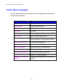
LCD DISPLAY
LCD Messages
4-16
4-17
HOW TO USE THE CONTROL PANEL
4-19
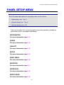
PANEL SETup MENU
4-21
vi
TABLE OF CONTENTS
CHAPTER 5 MAINTENANCE
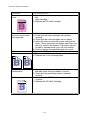
REPLACING THE CONSUMABLES
Toner Cartridges
Oil Bottle
Fuser Cleaner
Waste Toner Pack
OPC Belt Cartridge
Ozone Filter
Fusing Unit
120K Kit
5-1
5-5
5-9
5-13
5-16
5-18
5-22
5-23
5-27
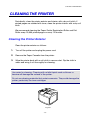
CLEANING THE PRINTER
5-35
REPACKING AND RELOCATING THE
PRINTER
OPTIONS
Lower Tray Unit (LT-26CL)
Duplex Unit (DX-2600)
CompactFlash Card / HDD Card (HD-6G/HD-EX)
RAM Expansion
5-43
5-45
5-45
5-50
5-56
5-63
CHAPTER 6 TROUBLESHOOTING
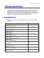
TROUBLESHOOTING
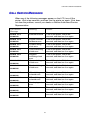
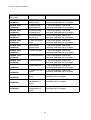
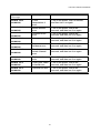
Error Messages
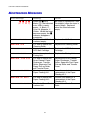
Maintenance Messages
Call Service Messages
Paper Jams
6-1
6-1
6-4
6-5
6-8
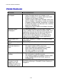
Q &A
Setting Up the Printer Hardware
Setting Up the Printer
Paper Handling
Printing
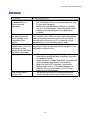
Print Quality
6-18
6-18
6-19
6-20
6-21
6-22
vii
TABLE OF CONTENTS
APPENDIX
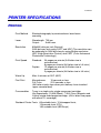
PRINTER SPECIFICATIONS
Printing
Functions
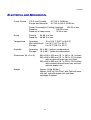
Electrical and Mechanical
A-1
A-1
A-2
A-3
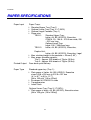
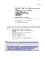
PAPER SPECIFICATIONS
A-4
SYMBOL/CHARACTER SETS
A-9
OCR Symbol Sets
A-9
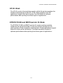
HP PCL Mode
A-10
EPSON Mode
A-12
IBM Mode
A-13
HP-GL Mode
A-14
Symbol Sets Supported by the Printer’s Intellifont Compatible Typefaces
A-15
Symbol Sets Supported by the Printer’s TrueType™ and Type 1 Font Compatible, and Original
Typefaces
A-17
INDEX
viii
REGULATIONS
IMPORTANT INFORMATION:
REGULATIONS
ELLEECCTTRRO
ON
NIIC
C EM
MIIS
SS
SIIO
ON
N NO
OTTIIC
CE
ES
S
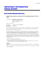
Federal Communications Commission (FCC) Compliance Notice (For U.S.A.
Only)
Responsible Party: Brother International Corporation
100 Somerset Corporate Boulevard
Bridgewater, NJ 08807-0911, USA
TEL: (908) 704-1700
declares, that the products
Product Name:
Model Number:
Product Options:
Brother Laser Printer HL-2600CN
HL-2600CN
ALL
complies with Part 15 of the FCC Rules. Operation is subject to the following two conditions: (1) This device
may not cause harmful interference, and (2) this device must accept any interference received, including
interference that may cause undesired operation.
This equipment has been tested and found to comply with the limits for a Class B digital device, pursuant to
Part 15 of the FCC Rules. These limits are designed to provide reasonable protection against harmful
interference a residential installation. This equipment generates, uses, and can radiate radio frequency energy
and, if not installed and used in accordance with the instructions, may cause harmful interference to radio
communications. However, there is no guarantee that interference will not occur in a particular installation. If
this equipment does cause harmful interference to radio or television reception, which can be determined by
turning the equipment off and on, the user is encouraged to try to correct the interference by one or more of the
following measures:
-
Reorient or relocate the receiving antenna.
Increase the separation between the equipment and receiver.
Connect the equipment into an outlet on a circuit different from that to which the receiver is connected.
Consult the dealer or an experienced radio/TV technician for help.
Important
A shielded interface cable should be used in order to ensure compliance with the limits for a Class B digital
device.
Changes or modifications not expressly approved by Brother Industries, Ltd. could void the user’s authority to
operate the equipment.
ix
REGULATIONS
Industry Canada Compliance Statement (For Canada Only)
This Class B digital apparatus complies with Canadian ICES-003.
Cet appareil numérique de la classe B est conforme à la norme NMB-003 du Canada.
Declaration of Conformity (For Europe)
We,
Brother Industries, Ltd.,
15-1, Naeshiro-cho, Mizuho-ku, Nagoya 467-8561, Japan
declare that this product is in conformity with the following normative documents.
Safety:
EMC:
EN 60950,
EN 60825
EN 55022 Class B, EN 55024
EN 61000-3-2,
EN 61000-3-3
following the provisions of the Low Voltage Directive 73/23/EEC and the Electromagnetic Compatibility
Directive 89/336/EEC (as amended by 91/263/EEC and 92/31/EEC).
Issued by: Brother Industries, Ltd.
Information & Document Company
Radio Interference (220-240 V Model Only)
This printer complies with EN55022(CISPR Publication 22)/Class B.
Before this product is used, ensure that you use a double-shielded interface cable with twisted-pair conductors
and that is marked “IEEE 1284 compliant”. The cable must not exceed 1.8 meters in length.
International ENERGY STAR® Compliance Statement
ENERGY STAR® is a U.S. registered mark.
The purpose of the International ENERGY STAR® Program is to promote the development and popularization of
energy-efficient office equipments.
As an ENERGY STAR® Partner, Brother Industries, Ltd. has determined that this product meets the ENERGY
STAR® guidelines for energy efficiency.
x
REGULATIONS
Laser Notices
Laser Safety (120 V Model Only)
This printer is certified as a Class I laser product under the U.S. Department of Health and Human Services
(DHHS) Radiation Performance Standard according to the Radiation Control for Health and Safety Act of
1968. This means that the printer does not produce hazardous laser radiation.
Since radiation emitted inside the printer is completely confined within protective housings and external
covers, the laser beam cannot escape from the machine during any phase of user operation. However, the
machine contains 5-milliwat, 700-800 nanometer wavelength, GaAIAs laser diodes. Direct (or indirect
reflected) eye contact with the laser beam might cause serious eye damage. Safety precautions and interlock
mechanisms have been designed to prevent any possible laser beam exposure to the operator.
FDA Regulations (For 120 V Model Only)
U.S. Food and Drug Administration (FDA) has implemented regulations for laser products manufactured on and
after August 2, 1976. Compliance is mandatory for products marketed in the United States. The label shown on
the back of the printer indicates compliance with the FDA regulations and must be attached to laser products
marketed in the United States.
MANUFACTURED:
BROTHER INDUSTRIES, LTD.
15-1 Naeshiro-cho, Mizuho-ku, Nagoya, 467-8561 Japan
This product complies with FDA radiation performance standards, 21 CFR Subchapter J.
Caution:
Use of controls, adjustments or performance of procedures other than those specified in this
manual may result in hazardous radiation exposure.
xi
REGULATIONS
IEC 60825 Specification (220 - 240 V Model Only)
This printer is a Class 1 laser product as defined in IEC 60825 specifications. The label shown below is attached
in countries where required.
CLASS 1LASER PRODUCT
APPAREIL Å LASER DE CLASSE 1
LASER KLASSE 1 PRODUKT
This printer has a Class 3B Laser Diode that emits invisible laser radiation in the Scanner Unit. The Scanner
Unit should not be opened under any circumstances.
Caution: Use of controls, adjustments or performance of procedures other than
those specified in this manual may result in hazardous radiation
exposure.
The following caution label is attached on the cover of the scanner unit.
For Finland and Sweden
LUOKAN 1 LASERLAITE
KLASS 1 LASER APPARAT
Varoitus! Laitteen käyttäminen muulla kuin tässä käyttöohjeessa mainitulla tavalla saattaa altistaa käyttäjän
turvallisuusluokan 1 ylittävälle näkymättömälle lasersäteilylle.
Varning – Om apparaten används på annat sätt än i denna Bruksanvisning specificerats, kan användaren utsättas
för osynlig laserstrålning, som överskrider gränsen för laserklass 1.
xii
REGULATIONS
Safety Information
IMPORTANT - For Your Safety
To ensure safe operation the three-pin plug supplied must be inserted only into a standard three-pin power point
which is properly earthed through the normal household wiring.
Extension cords should not be used with the equipment. If it is essential that an extension cord has to be used,
it must be a three-pin plug type and correctly wired to provide proper grounding. Incorrectly wired extension
cords may cause personal injury and equipment damage.
The fact that the equipment operates satisfactorily does not imply that the power is earthed and that the
installation is completely safe. For your safety, if in any doubt about the effective grounding of the power,
consult a qualified electrician.
Caution
Use of controls or adjustment or performance of procedures other than those specified in this manual might
result in hazardous radiation exposure.
Disconnect device
This printer must be installed near a power outlet that is easily accessible. In case of emergencies, you must
disconnect the power cord from the power outlet to shut off the power completely.
Caution for batteries
Do not replace the battery. There is a danger of explosion if the battery is incorrectly replaced. Do not
disassemble, recharge or dispose of in fire. Used batteries should be disposed of according to local regulations.
Caution for LAN connection
Connect this product to the LAN connection which is not subjected to overvoltages.
IT power system (For Norway only)
This product is also designed for IT power system with phase to phase voltage 230V.
Opmerking / Oplaadbare Batterij Recycle Informatie (For Netherlands Only)
Bij dit product zijn batterijen geleverd. Wanneer deze leeg zijn,
moet u ze niet weggooien maar inleveren als Klein Chemisch Afval.
•
Geräuschemission / Acoustic Noise Emission (For Germany Only)
Lpa < 70 dB (A) DIN 45635-19-01-KL2
xiii
REGULATIONS
Wiring Information (For U.K. only)
Important
If the mains plug supplied with this printer is not suitable for your socket outlet, remove the plug from the
mains cord and fit an appropriate three pin plug. If the replacement plug is intended to take a fuse then fit the
same rating fuse as the original.
If a moulded plug is severed from the mains cord then it should be destroyed because a plug with cut wires is
dangerous if engaged in a live socket outlet. Do not leave it where a child might find it!
In the event of replacing the plug fuse, fit a fuse approved by ASTA to BS1362 with the same rating as the
original fuse.
Always replace the fuse cover. Never use a plug with the cover omitted.
WARNING - THIS PRINTER MUST BE PROPERLY EARTHED.
The wires in the mains cord are colored in accordance with the following code:
Green and yellow:
Blue:
Brown:
Earth
Neutral
Live
The colours of the wires in the main lead of this printer may not correspond with the colored markings
identifying the terminals in your plug.
If you need to fit a different plug, proceed as follows.
Remove a length of the cord outer sheath, taking care not to damage the colored insulation of the wires inside.
Cut each of the three wires to the appropriate length. If the construction of the plug permits, leave the green and
yellow wire longer than the others so that, in the event that the cord is pulled out of the plug, the green and
yellow wire will be the last to disconnect.
Remove a short section of the colored insulation to expose the wires.
The wire which is colored green and yellow must be connected to the terminal in the plug which is marked with
the letter “E” or by the safety earth symbol or colored green or green and yellow.
The wire which is colored blue must be connected to the terminal which is marked with the letter “N” or
colored black or blue.
The wire which is colored brown must be connected to the terminal which is marked with the letter “L” or
colored red or brown.
The outer sheath of the cord must be secured inside the plug. The colored wires should not hang out of the plug.
xiv
CHAPTER 1 INTRODUCTION
CHAPTER 1
INTRODUCTION
CHAPTER 1 INTRODUCTION
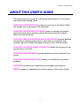
ABOUT TH IS USER’S GUIDE
This manual acts as your guide to the setup and operation of your printer
and covers the following topics:
CHAPTER 1 INTRODUCTION provides an overview of the printer. Read
this chapter first to get familiar with the printer.
CHAPTER 2 DRIVER AND SOFTWARE gives you general information
about the printer driver and the software. Be sure to read this chapter
before you use the printer.
CHAPTER 3 BEFORE WORKING WITH THE PRINTER provides detailed
information for setting up the printer to work with your computer and
software. Be sure to read this chapter before you work with the printer.
CHAPTER 4 CONTROL PANEL OPERATION details the functions of the
panel buttons and LEDs.
CHAPTER 5 MAINTENANCE provides guidance on how to maintain your
printer.
CHAPTER 6 TROUBLESHOOTING helps you troubleshoot any printer
problems.
APPENDIX contains printer specifications and paper specifications.
INDEX provides an alphabetical list of the contents of this User’s Guide.
1-1
CHAPTER 1 INTRODUCTION
Note
When you read this User’s Guide, note the following:
• This User’s Guide contains instructions or steps to teach you the various
operations of the printer. Please remember that the instructions always
assume you started with the factory settings, particularly in Chapter 2
and Chapter 3. If you change the settings, particularly the emulation
mode, the display messages change accordingly.
• The paper size has been factory set to letter or A4, depending upon the
final destination of the printer. Some display messages vary according to
this setting.
1-2
CHAPTER 1 INTRODUCTION
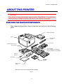
ABOUT THIS PRINTER
! Warning
This printer is heavy and weighs approximately 39kg (86 lbs). To avoid injury
when moving or lifting this printer, be sure to use at least two people.
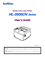
CHHEECCKKIINNG
AR
OM
RTTO
MP
PO
ON
ON
N CO
NE
EN
G TTH
NTTS
S
HE
E CA
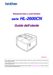
After unpacking the printer, check to see that you have all of the following
parts:
OPC Belt Cartridge
Printer
Fuser Cleaner
(CR-3CL)
*
Power Cord
Standard Paper Cassette
(pre-installed)
Toner Cartridge
(Black (TN03BK), Cyan (TN03C),
Magenta (TN03M), Yellow (TN03Y))
Oil Bottle
(FO-2CL)
Oil Syringe
CD-ROM
Quick Setup
Guide*
*These parts are in the Localization Kit in Europe.
Fig. 1-1
1-3
*
CHAPTER 1 INTRODUCTION
Note
Depending on the country where you purchased the printer, you may have
additional parts that are not listed above.
! Caution
The Toner Cartridges, OPC Belt cartridge, Oil Bottle and Fuser Cleaner are
packed inside a separate carton as a starter kit. Do NOT open them now.
Only open them when you are ready to install them. The OPC Belt Cartridge
must not be exposed to light for any length of time or it will be damaged.
Note
An interface cable is not a standard accessory. Please purchase the
appropriate cable for the interface you intend to use. Parallel cables should
be IEEE 1284 compliant and should not exceed 1.8 meters (6 feet) in length.
Depending on the country where you purchased the printer, the power cord
may differ slightly from this diagram.
Note
Depending on the country you live in and the HL-2600CN series model
purchased, you may have additional parts not listed above.
Note
We recommend keeping spares of the following consumables at all times.
When these are exhausted, the printer will cease printing.
• Toner Cartridges (TN-03BK, TN-03C, TN-03M, TN-03Y)
• Waste Toner Pack (WT-3CL)
• Oil Bottle (FO-2CL)
• Fuser Cleaner (CR-3CL)
• OPC Belt Cartridge (OP-3CL)
1-4
CHAPTER 1 INTRODUCTION
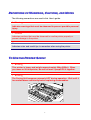
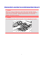
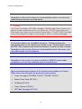
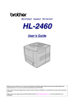
GEENNEERRAALL VIIEEW
W
Top Cover
Control Panel
Front Cover
Power Button
Paper Cassette
Fig. 1-2
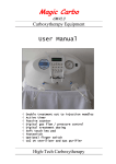
Controller Card
Power Cord
Connector
Rear Access Cover
Rear Side Cover
Fig. 1-3
1-5
CHAPTER 1 INTRODUCTION
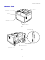
FEEAATTUURREESS
This printer has the following standard features.
2400 DPI Class Resolution
This printer prints at a default resolution of 600 dots per inch (dpi). You can
achieve a higher print quality equivalent to 2400 dpi class resolution by
utilizing these Brother technologies: High Resolution Control (HRC) and
Color Advanced Photoscale Technology (CAPT).
High Speed and Color Laser Printing
You can print crisp images in brilliant 24-bit color.
This printer can print at speeds up to 24 pages per minute in monochrome
mode and 6 pages per minute in full color mode. The HL-2600CN controller
utilizes a high speed 64-bit RISC microprocessor and special hardware
chips, to ensure fast print job processing.
Color Advanced Photoscale Technology (CAPT)
This printer can print graphics in 256 shades for each color in HP® color
printer PCL5C™ emulation and BR-Script level 3, producing nearly
photographic quality. CAPT is most effective when printing photographic
images.
High Resolution Control (HRC)
The High Resolution Control (HRC) technology provides clear and crisp
printouts and improves even 600-dpi resolution output. HRC is most
effective when printing text.
1-6
CHAPTER 1 INTRODUCTION
Maintenance-Free and Economical Toner Cartridge
The toner cartridge can print up to 12,000 (Black) and 7,200 (Cyan,
Magenta and Yellow) single-sided pages at 5% coverage. This printer uses
one piece, easy-to-replace toner cartridges.
Universal Paper Cassette
This printer loads paper automatically from the paper cassette. Since the
paper cassette is a universal type, a number of different paper sizes can be
used. Even envelopes can be loaded from the paper cassette. For detailed
paper specifications, see ‘Paper Handling’ in Chapter 3.
Three Interfaces
This printer has a high speed, bi-directional parallel interface, USB and
Ethernet 10/100BaseTX.
If your application software supports the bi-directional parallel interface, you
can monitor the printer status. It is fully compatible with the industrystandard bi-directional parallel interface.
The Brother network board (NC-4100h) is factory installed in the HL2600CN, which enables you to use this printer in the TCP/IP, IPS/SPX,
AppleTalk, DLC/LLC, Banyan VINES, DEC LAT and NetBEUI
environments. Also, many useful utilities, such as BRAdmin Professional
for the administrator and Brother network printing software, are included in
the CD-ROM supplied with the HL-2600CN printer. For setup, see the
Network User’s Guide.
Automatic Interface Selection
This printer can automatically select the bi-directional parallel, USB or
Ethernet 10/100BaseTX interface, depending on the interface port through
which it receives data. With this feature, the printer can be connected to
more than one computer.
1-7
CHAPTER 1 INTRODUCTION
Five Emulation Modes
This printer can emulate the Hewlett-Packard® Color PCL® 5C language
(PCL6® in monochrome printing) printers, PostScript®3 language emulation
(Brother BR-Script3) printers, the industry-standard HP-GL™ plotter as well
as EPSON® FX-850™ and IBM® Proprinter XL® printers (for monochrome
printing only). You can print with all application programs that support one
of these printers.
Automatic Emulation Selection
This printer can automatically select the printer emulation mode, depending
on the print commands it receives from the computer software. With this
feature, many users can share the printer on a network.
Data Compression Technology
This printer can internally compress the received graphics and font data in
its memory so it can print larger graphics and more fonts without the need
for additional memory.
1-8
CHAPTER 1 INTRODUCTION
Fonts
This printer has 66 scalable and 12 bitmapped fonts. The fonts that can be
used will vary according to the selected emulation mode.
In PCL mode, you can also print the 13 kinds of bar codes listed below. In
BR-Script mode, the printer has 165 scalable fonts.
Bar Code Printing
This printer can print the following 13 types of bar codes:
• Code 39
• UPC-E
• Interleaved 2 of 5
• Codabar
• EAN-8
• FIM (US-PostNet)
• EAN-13
• Post Net (US-PostNet)
• EAN- 128
• ISBN (EAN)
• Code 128
• ISBN (UPC-E)
• UPC-A
Panel Lock Function
If the panel key settings have been changed, the printer may not work as
you expect. If you are an administrator of this printer, you can lock your
settings to prevent changes from being made. See “LOCK PANEL” in the
“SETUP” menu in Chapter 4.
1-9
CHAPTER 1 INTRODUCTION
Power Save Mode
This printer has a power saving mode. Since laser printers consume power
to keep the fixing assembly at a high temperature, this feature can save
electricity when the printer is on but not being used. The factory setting of
the Power Save mode is ON so that it complies with the new EPA Energy
Star specification.
Toner Save Mode
This printer has an economical Toner Save Mode. By using this feature you
can substantially reduce operating costs and extend the life expectancy of
the toner cartridges.
Reprint Function
You can reprint the last print job with a touch of a panel button. This feature
allows reprinting of multiple copies of the job without sending the data again
from the computer.
If you do not install an HDD in or CompactFlash card, you can reprint from
RAM. See “REPRINT BUTTON” in Chapter 4 for more information.
When there is not enough memory to print the last job, you can reprint the
last print page.
1-10
CHAPTER 1 INTRODUCTION
PANTONE® Calibrated
There are many variables in process reproduction of colors generated by
the HL-2600CN, any one of which may affect the quality of the PANTONE
Color simulation, including:
1.
2.
3.
4.
Type of paper used
Type of toner used
Effective final resolution
Dot structure/halftones
For optimal results, we recommend that the following materials and settings
be used:
NEUSIEDLER Color Copy 90g
Brother Toner Cartridges TN-03 BK/C/M/Y for “2” above.
Pantone Mode (600 x 600 dpi)
Network
Ethernet 10/100BaseTX enables you to use the printer in the following
environments:
(TCP/IP, IPX/SPX, AppleTalk, DLC/LLC, VINES, LAT, NetBEUI)
Also, many useful utilities, such as BRAdmin Professional and Brother
Network Printing software for the Network administrator, are included. For
details of the utilities, see the documentation included on the CD-ROM.
1-11
CHAPTER 1 INTRODUCTION
OPPTTIIO
ON
NS
S
The following options are available for this printer:
Paper Handling
Lower Tray Unit (LT-26CL)
A lower tray unit expands the paper source capacity. You can load extra
paper or different sizes of paper. You can load Letter, A4, B5 (JIS and ISO)
or Executive size (176x250 to 215.9x297mm) paper into this cassette.
Legal Cassette (LC-26LG)
If you wish to print on Legal sized paper, you must use this cassette.
However, since it is not restricted to Legal size paper, you can choose to
load Letter, A4, B5 (JIS/ISO), Executive or Envelopes in this cassette.
Duplex Unit (DX-2600)
By installing the Duplex Unit DX-2600, you can perform duplex printing.
You can print on Letter, A4, B5 (JIS/ISO), Executive and Legal size paper
with the Duplex Unit installed.
Hard Disk Drive (HD-6G/HD-EX)
By installing the Hard Disk Drive, HD-6G/HD-3X, you can save macros,
print log and fonts on it, and also select your print job and re-print it through
the network.
1-12
CHAPTER 1 INTRODUCTION
RAM
RAM Expansion
By installing commercial memory modules you can expand the memory
capacity up to 384 Mbytes.
Note
Installation instructions for each of these options will be included with the
optional accessory.
OPPEERRAATTIINNG
NV
OR
VIIR
RA
AG
RO
GE
ON
E EN
NM
ME
GA
EN
NTT
AN
ND
D STTO
Please note the following requirements before using the printer.
Power Supply
Use the printer within the specified power range.
AC power:
±10% of the rated power voltage
Frequency:
50/60 Hz (120V or 220-240 V)
The power cord, including extensions, should not exceed 5 meters (16.5
feet).
Do not share the same power circuit with other high-power appliances,
particularly an air conditioner, copier or shredder. If you must use the printer
with these appliances, we recommend that you use a voltage transformer or
a high-frequency noise filter.
Use a voltage regulator if the power source is not stable.
1-13
CHAPTER 1 INTRODUCTION
Environment
Use the printer only within the following ranges of temperature and
humidity:
Ambient temperature:
20° C to 32.5° C (50° F to 90.5° F)
Ambient humidity:
20% to 80% (without condensation)
Do not block the air exit on top of the printer. Do not place objects on top of
the printer, especially on the air exit.
Ensure that the printer Ozone Filter is installed at all times.
Ventilate the room where you use the printer.
Do not place the printer where it will be exposed to direct sunlight. If set up
near a window is unavoidable, use blinds to protect the printer from direct
sunlight.
Do not install the printer near devices that contain magnets or generate
magnetic fields.
Do not subject the printer to strong physical shocks or vibrations. Do not
expose the printer to open flames or salty or corrosive gasses.
1-14
CHAPTER 1 INTRODUCTION
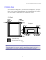
Place the printer on a flat, horizontal surface.
Keep the printer clean. Do not install the printer in a dusty place.
Do not install the printer near an air conditioner.
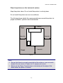
The following figure details the recommended area around the printer for
proper ventilation, operation and maintenance.
20cm(8")
Rear
50cm(20")
50cm(20")
70cm(28")
Front
Fig. 1-4
Note
• Ensure that there is enough space behind the printer so you can easily
access the rear cover or Duplex unit if a paper jam occurs.
• Make sure the Paper Cassette does not extend past the edge of the
table where the printer is located.
1-15
CHAPTER 2 DRIVER AND SOFTWARE
CHAPTER 2
DRIVER AND SOFTWARE
CHAPTER 2 DRIVER AND SOFTWARE
PRINTER DRIVER
A Printer Driver is software that translates data from the format used by a
computer into the format required by a particular printer. Typically, this
format is a printer command language or page description language.
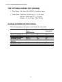
The printer drivers for the following operating systems are on the supplied
CD-ROM. Printer driver updates can be downloaded from the Brother
Solutions Center at http://solutions.brother.com.
For Windows® 95/98/Me, Windows NT® 4.0 and Windows® 2000/XP
• PCL (Hewlett-Packard laser printer-LaserJet) driver
• BR-Script (PostScript3 language emulation) driver
For Macintosh
• BR-Script (PostScript3 language emulation) driver (For more
information, see the Network User’s Guide on the CD-ROM.)
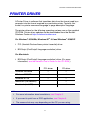
PCL driver
PS driver
Windows 95/98/Me
!
!
Windows 2000/XP
!
!
Windows NT4.0
!
!
Macintosh (via Network)
!
Macintosh (via USB)
!
Note
• For more information about emulations, see Chapter 3.
• If you want to print from a DOS application, see Chapter 6.
• The screen shot may vary depending on the OS you are using.
2-1
CHAPTER 2 DRIVER AND SOFTWARE
FEEAATTUURREESS IINN TTHHEE PCL PRRIINNTTEERR DRRIIVVEERR
(WIINNDDO
OW
WS
S 95/98/ME
E US
SE
ER
RS
S ON
NLLY
Y)
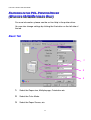
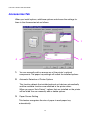
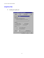
For more information, please see the on-line Help in the printer driver.
You can also change settings by clicking the illustration on the left side of
the tab.
Basic Tab
1
2
3
1.
Select the Paper size, Multiple page, Orientation etc.
2.
Select the Color Mode.
3.
Select the Paper Source, etc.
2-2
CHAPTER 2 DRIVER AND SOFTWARE
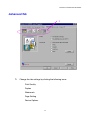
Advanced Tab
1
1.
Change the tab settings by clicking the following icons:
Print Quality
Duplex
Watermark
Page Setting
Device Options
2-3
CHAPTER 2 DRIVER AND SOFTWARE
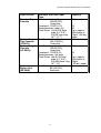
Print Quality
Select the Quality, Color matching mode, and Calibration settings.
• You can change the Quality as follows:
Normal
600 dpi
Fine
2400 dpi class with CAPT*
*CAPT (Color Advanced PhotoScale Technology)
= The finest print mode. Use this mode to print precise
images such as photographs. Since the print data is
much larger than in normal mode, processing time / data
transfer time and printing time will be longer.
• You can change the Color Matching mode as follow:
Match Monitor
Photo
Graphics
Vivid / Text
None
2-4
CHAPTER 2 DRIVER AND SOFTWARE
Duplex
To use duplex printing, you will need to install the optional Duplex unit onto
your printer. If you select the duplex button, the dialogue box for making
duplex settings will appear. Six types of duplex binding directions are
available for each orientation.
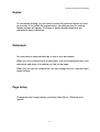
Watermark
You can place a watermarked logo or text in your documents.
When you use a bitmap file as a watermark, you can change the size of the
watermark and place it anywhere you like on the page.
When you use text as a watermark, you can change the font, darkness and
angle settings.
Page Setup
Change the print image scaling, and then select Mirror / Reverse print
options.
2-5
CHAPTER 2 DRIVER AND SOFTWARE
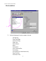
Device Options
1
1.
Set the following print function modes in this tab:
Job Spooling
Toner Save Mode
Quick Print Setup
Sleep Time
Status Monitor
Macro
Administrator
Insert Command/File
Print Setting
Print Setting (For monochrome only)
Page Protection
Print Date & Time
2-6
CHAPTER 2 DRIVER AND SOFTWARE
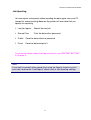
Job Spooling
You can reprint a document without sending the data again from your PC
(except for secure printing) because the printer will save data that you
specify for reprinting.
• Last job reprint:
Reprint the last job
• Secure Print:
Print the data with a password
• Public: Save the data without a password
• Proof:
Save the data and print it
For more information about the Reprint function, see “REPRINT BUTTON”
in Chapter 4.
Note
If you want to prevent other people from using the Reprint function to print
your data, remove the “Use Reprint” check mark in Job Spooling settings.
2-7
CHAPTER 2 DRIVER AND SOFTWARE
Accessories Tab
When you install options, add those options and choose the settings for
them in the Accessories tab as follows.
1
3
2
1.
You can manually add or remove any of the printer’s optional
components. The paper tray settings will match the installed options.
2.
Automatic Detection of Printer Options
This function detects the installed optional unit devices automatically
and the available functions are reflected in the printer driver.
When you press “Auto Detect,” options that are installed on the printer
will be listed. You can manually add or delete options.
3.
Paper Source Setting
This feature recognizes the size of paper in each paper tray
automatically.
2-8
CHAPTER 2 DRIVER AND SOFTWARE
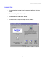
Support Tab
• You can download the latest driver by accessing the Brother Solutions
Center.
• You can see the printer driver version.
• You can check the current driver settings.
• You can print the Configuration page and Font page(s).
2-9
CHAPTER 2 DRIVER AND SOFTWARE
FEEAATTUURREESS IINN TTHHEE PS PPRRIINNTTEERR DDRRIIVVEERR
(WIINNDDO
OW
WS
S 95/98/ME
EU
US
SE
ER
RS
SO
ON
NLLY
Y)
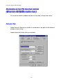
For more information, please see the on-line Help in the printer driver.
Details Tab
Select the port where your printer is connected or the path to the network
printer you are using.
Select the printer driver that you installed.
2-10
CHAPTER 2 DRIVER AND SOFTWARE
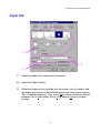
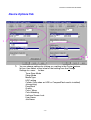
Paper Tab
1
2
3
1.
Select the Paper size, Layout and Orientation.
2.
Select the Paper Source.
3.
When the Duplex unit is installed onto the printer, you will need to add
the duplex unit as one of the installed options first (see Device Options
Tab – Installable Options). Click on the More Options button to choose
between Flip on Short edge, Flip on Long edge or None for Duplex
printing.
2-11
CHAPTER 2 DRIVER AND SOFTWARE
Graphics Tab
1.
Set the print quality, etc.
2-12
CHAPTER 2 DRIVER AND SOFTWARE
Device Options Tab
1
2
1.
You can change settings by clicking on a setting in the Printer features
list box, then select a new value for that setting from the Change
Settings for: xxxxx list box.
Toner Save Mode
Sleep Mode
Media Type
HRC setting
Collate (Only when an HDD or CompactFlash card is installed)
Job spooling
Pass Word
Quality
Color / Mono
Color Matching
Halftone Screen Lock
User Name
Job Name
2-13
CHAPTER 2 DRIVER AND SOFTWARE
2.
Select the installed options from the list.
You can change settings by clicking on a setting in the Installable
options list box, then select a new value for that setting from the
Change Settings for: xxxx list box.
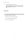
Job Spooling
Because the printer will save data that you specify for reprinting, you can
print a document without resending the data from your PC or sending the
password again (except Secure printing).
• Secure Print: Print the data with a password
• Public: Save the data without a password
• Proof: Save the data and print it
2-14
CHAPTER 2 DRIVER AND SOFTWARE
SO
OFFTTW
WA
AR
RE
E FFO
OR
RN
NE
ETTW
WO
OR
RK
KS
S
BRAdmin Professional
BRAdmin professional is a utility for managing your Brother network
enabled printers that are running under Windows 95/98/Me, Windows 2000
and Windows NT 4.0. It allows you to easily configure and check the status
of your network-enabled printer.
Storage Manager
Brother Storage Manager software can manipulate the printer forms that
you may have stored in a CompactFlash or 2.5” HDD.
You can print a fixed form document at any time from the control panel.
To make a fixed document, you must write Fonts, Macros, or fixed forms to
the Storage Device of your printer.
Analysis Tool Software
By adding a HDD or CompactFlash Card to the printer, you can obtain print
logs by enabling the log function with the embedded web management.
Then you can gain cost analysis capability by loading these print logs into
the Analysis Tool Software.
Analysis Tool Software is a 32-bit Windows application designed to manage
important information about a print job, such as the username, job name
and number of printed pages. Using this software, you can easily associate
printing costs with users or groups of users.
2-15
CHAPTER 2 DRIVER AND SOFTWARE
Driver Deployment Wizard
Save time and effort by using the Brother Driver Deployment Wizard
software to automate the installation and configuration of Brother networked
printers in a TCP/IP environment.
Use the Wizard to configure the printer TCP/IP settings and to specify the
Printer driver to be used. The Wizard can then create an Executable file that
can be e-mailed to other network users. When run, the Executable file
installs the appropriate printer driver and network print software directly on
the remote PC.
To access the Driver Deployment Wizard, insert the CD-ROM supplied with
the printer into your CD-ROM drive, click the Install Software icon, and then
select the Driver Deployment Wizard.
2-16
CHAPTER 2 DRIVER AND SOFTWARE
SO
OFFTTW
WA
AR
RE
E FFO
OR
R WIIN
ND
DO
OW
WS
S CO
OM
MP
PU
UTTE
ER
RS
S
You can install the Software from the supplied CD-ROM as follows:
1.
Insert the CD-ROM into the CD-ROM drive. The opening screen
appears automatically. Follow the instructions on the screen.
2.
Click the Install Software icon on the Menu screen.
3.
Click “Printer Driver”, and then follow the on screen instructions. The
printer driver will complete the installation.
2-17
CHAPTER 2 DRIVER AND SOFTWARE
SO
OFFTTW
WA
AR
RE
E FFO
OR
R MA
AC
CIIN
NTTO
OS
SH
H CO
OM
MP
PU
UTTE
ER
R
This printer supports Mac OS versions 8.6, 9.0, 9.04, 9.1, 9.2 and X.
Apple LaserWriter 8 Driver
The Apple LaserWriter Driver may have been installed with your system. It
is also available at http://www.apple.com.
LaserWriter 8 version 8.6.5 and 8.7 have been tested for use with the
Brother HL-2600CN.
PostScript Printer Description Files (PPDs)
PPDs, in combination with the Apple LaserWriter 8 Driver, access the
printer features and allow the computer to communicate with the printer.
An installation program for the PPDs (“BR-Script PPD Installer”) is provided
on the CD-ROM.
2-18
CHAPTER 2 DRIVER AND SOFTWARE
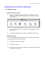
Installing the Printer Driver for Macintosh
For Network users*
For Mac OS 8.6 to 9.2 Users
1.
Turn on your Macintosh computer. Insert the CD-ROM into your CDROM drive. Double-click the Start Here! Icon. Follow the instructions
on the screen.
2.
To install the BR-Script PPD file, click the Install Software icon on the
Menu screen.
3.
To set up the LaserWriter driver, refer to the Network User’s Guide.
For Mac OS X Users
(It is not possible to install the BR-Script PPD file from the Install Software
icon, please follow the instructions below.)
1.
Turn ON your Macintosh computer.
2.
Turn OFF your printer.
3.
Connect one end of the network cable to your printer and the other end
to a free port on your hub.
2-19
CHAPTER 2 DRIVER AND SOFTWARE
4.
Turn ON your printer.
5.
Insert the CD-ROM into your CD-ROM drive. Open the Mac OS X
folder.
6.
Open your language folder.
7.
Double-click the install icon. Follow the instructions on the screen.
8.
Open the Macintosh HD icon.
9.
Open the Applications folder. Open the Utilities folder.
10. Open the Print Center icon.
11. Click the Add Printer button.
12. Select BRN_xxxxxx_P1_AT and then click the Add button. (xxxxxx is
the last six digits of the Ethernet address. For more information, see
Chapter 7 of the Network User’s Guide.)
13. Select Quit Print Center from the Print Center menu.
14. The Setup is now complete.
* For USB users, please see the “Driver Installation Guide” for installing the
printer driver.
2-20
CHAPTER 2 DRIVER AND SOFTWARE
PRINTER SETTINGS
FAACCTTO
ETTTTIIN
OR
RY
NG
Y SE
GS
S
The printer settings have been set at the factory before shipment. They are
called “Factory settings.” Although you can operate the printer with these
factory settings unchanged, you can tailor the printer with user settings.
Please see “List of Factory Settings” in Chapter 4.
Note
Changing the user settings does not affect the factory settings. You cannot
modify the present factory settings.
The changed user settings can be restored to the default factory settings
with the RESET MENU mode. For more information, see Chapter 4.
2-21
CHAPTER 3 BEFORE WORKING WITH THE PRINTER
CHAPTER 3
BEFORE WORKING WITH THE
PRINTER
CHAPTER 3 BEFORE WORKING WITH THE PRINTER
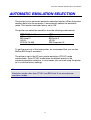
AUTOMATIC EMULATION SELECTION
This printer has an automatic emulation selection function. When the printer
receives data from the computer, it automatically selects the emulation
mode. This function has been factory set to ON.
The printer can select the emulation from the following combinations:
EPSON (Default)
HP LaserJet
BR-Script 3
HP-GL
EPSON FX-850
IBM
HP LaserJet
BR-Script 3
HP-GL
IBM Proprinter XL
To get the most out of this laser printer, we recommend that you use the
Brother BR-Script 3 emulation.
The printer is set to the HP color printer emulation (PCL5C) mode
automatically. Since PCL5C mode takes the highest priority in the
automatic emulation selection, in most cases you can start using the printer
as it is with the factory settings.
Note
Emulation modes other than PCL5C and BR-Script 3 are monochrome
emulation modes.
3-1
CHAPTER 3 BEFORE WORKING WITH THE PRINTER
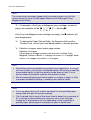
You can select the emulation mode manually by using the control panel to
access the EMULATION menu in SETUP mode. For more information, see
Chapter 4.
Note
When you use the automatic emulation selection, note the following:
• The EPSON or IBM emulation mode priority must be selected, because
the printer cannot distinguish between them. Since the factory setting is
EPSON emulation mode, you might need to select the IBM emulation
mode by using the control panel to access the EMULATION menu in
SETUP mode.
• Try Automatic emulation selection with your application software or
network server. If it does not work properly, select the emulation mode
manually by using either the printer control panel or the emulation
selection commands from your software.
3-2
CHAPTER 3 BEFORE WORKING WITH THE PRINTER
AUTOMATIC INTERFACE SELECTION
This printer has an automatic interface selection function. When the printer
receives data from the computer, it automatically selects the IEEE 1284
Parallel or USB interface whichever is appropriate.
When you use the parallel interface, you can turn the high-speed and bidirectional parallel communications on or off by using the control panel to
access the PARALLEL menu in INTERFACE mode. For more information,
see Chapter 4. Since the automatic interface selection mode has been
factory set to ON, simply connect the interface cable to the printer. (Note:
Always turn off both your computer and printer when connecting or
disconnecting the cable).
When necessary, select the interface or the serial communications
parameters manually by using the control panel to access the INTERFACE
mode. For more information, see Chapter 4. For the settings on your the
computer, please refer to your user’s manual for your computer or
application software.
Note
When you use the automatic interface selection, note the following:
• This function takes a few seconds to work. If you want to speed up
printing, select the required interface manually by using the control panel
to access the SELECT menu in INTERFACE mode.
If you typically use only one interface, we recommend you select that
interface in the INTERFACE mode. If only one interface is selected, the
printer will allocate the entire input buffer to that interface.
3-3
CHAPTER 3 BEFORE WORKING WITH THE PRINTER
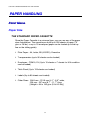
PAPER HANDLING
PRRIINNTT MEEDDIIAA
Paper Size
THE STANDARD PAPER CASSETTE
Since the Paper Cassette is a universal type, you can use any of the paper
sizes listed below. The cassette can hold up to 250 sheets of paper (75
g/m2 or 20 lbs.) or up to 15 envelopes (paper can be loaded up to the top
line on the sliding guide).
• Plain Paper: A4, Letter, B5 (JIS/ISO), Executive
• Transparencies (up to 50 sheets can be loaded)
• Envelopes: COM10, DL (Up to 15 sheets or 7 sheets for H/H condition
can be loaded)
• Thick Stock (Up to 120 sheets can loaded)
• Labels (Up to 80 sheets can loaded)
• Other Sizes: 104.8 mm - 215.9 mm (4.1” - 8.5”) wide,
220 mm - 297 mm (8.7” - 11.7”) long
[Weight = 64 to 163 g/m2 (18 to 43 lbs)]
3-4
CHAPTER 3 BEFORE WORKING WITH THE PRINTER
THE OPTIONAL LOWER TRAY CASSETTE (LT-26CL)
The cassette can hold up to 500 sheets of paper (75 g/m2 or 20 lbs.). The
maximum capacity is 52 mm paper height.
• Plain Paper: A4, Letter, B5 (JIS/ISO), Executive
• From 176 mm x 250 mm (6.9” x 9.8”) to 215.9 mm x 297 mm (8.5” 11.7”) [Weight = 64 to 105 g/m2 (18 to 28 lbs)]
• Thick Stock [Weight = 90 to 105 g/ m2 (24 to 28 lbs)], and the maximum
capacity is 52 mm loading height.
• Other Sizes: 176 mm - 215.9 mm (6.9” - 8.5”) wide,
250 mm - 297 mm (9.8” - 11.7”) long
[Weight = 64 to 105 g/m2 (18 to 28 lbs)]
THE OPTIONAL LEGAL CASSETTE (LC-26LG)
The cassette can hold up to 250 sheets of paper (75 g/m2 or 20 lbs.). If you
want to print on legal size paper, you must use this cassette.
• Plain Paper: A4, Letter, B5 (JIS/ISO), Executive, Legal
• Thick Stock (Up to 120 sheets can loaded)
• Labels (Up to 80 sheets can loaded)
• Transparencies (up to 50 sheets can be loaded)
• Envelopes: COM10, DL (Up to 15 sheets or 7 sheets for H/H condition
can be loaded)
• Other Sizes: 104.8 mm - 215.9 mm (4.1” - 8.5”) wide,
220 mm - 355.6 mm (8.7” - 14”) long
[Weight = 64 to 163 g/m2 (18 to 43 lbs)]
3-5
CHAPTER 3 BEFORE WORKING WITH THE PRINTER
THE OPTIONAL DUPLEX UNIT (DX-2600)
• Plain Paper: A4, Letter, B5 (JIS/ISO), Executive, Legal
• Other Sizes: 104.8 mm - 215.9 mm (4.1” - 8.5”) wide,
220 mm - 355.6 mm (8.7” - 14”) long
[Weight = 64 to 105 g/m2 (18 to 28 lbs)]
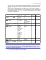
SUITABLE PAPER SPECIFICATIONS
The following paper specifications are suitable for this printer.
Item
Basis Weight (g/m2)
Thickness (µm)
Smoothness (Bekk)
Stiffness (Clark)
Surface Resistance
X109 (!)
Brightness (%)
Grain Direction
Recommended
Paper
Specification
82±5
95±6
90±20
100±15
10-100
Xerox 4024
Hammermill
Laserprint
75
102
35
100
10-100
90
105
120
90
10-100
85±2
Long
80
Long
85
Long
3-6
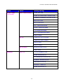
CHAPTER 3 BEFORE WORKING WITH THE PRINTER
Paper Source
Standard Paper
Cassette
Optional Lower
Tray Cassette
(LT-26CL)
Optional Legal
Cassette
(LC-26LG)
Optional
Duplex Unit
(DX-2600)
Available Size and Paper
Type
Cut sheet: Letter, A4,
B5(JIS/ISO),
Executive,
Envelopes: COM 10, DL
Transparencies: Letter, A4
Other Sizes: 104.8-215.9mm
wide (4.1”-8.5”)
220-297mm long
(8.7”-11.7”)
Cut Sheet: Letter, A4,
B5 (JIS/ISO),
Executive
Cut Sheet: Legal, Letter, A4,
B5(JIS/ISO),
Executive
Envelopes: COM10, DL
Transparencies: A4, letter
Other Sizes: 104.8-215.9mm
wide (4.1”-8.5”)
220-355.6mm long
(8.7”-14”)
Cut Sheet: Legal, Letter, A4,
B5 (JIS/ISO),
Executive
3-7
Capacity
250
15
50
Up to approx.
250 sheets of
75g/m2 (20 lbs.)
paper
500
250
50
5
Up to approx.
250 sheets of
75g/m2
( 20 lbs.) paper
CHAPTER 3 BEFORE WORKING WITH THE PRINTER
Recommended Paper
The recommended paper for this printer is:
Xerox 4024, Hammermill Laserprint, NEUSIEDLER Color Copy 90g or
equivalent
Note
• To get the best output quality and to avoid any damage, use smooth
white paper.
• We recommend that you test paper, especially special sizes and types
of paper, on this printer before purchasing large quantities.
• Print quality will vary depending on the paper being used.
Note
Do not load Envelopes, Transparencies, Labels or Thick Stock (29lb or
more) into the Optional Lower Tray Unit. It may cause paper jams.
3-8
CHAPTER 3 BEFORE WORKING WITH THE PRINTER
Printable Area
The Printable Area depends on the settings in your application. The figure
below shows the physical printable area and non-guaranteed print area for
the various types of paper that can be used with this printer.
Cut Sheets
Envelopes
Unprintable Area
Non guaranteed Print Area
Fig. 3-1
Note
If you use paper that does not meet the specifications listed in this User’s
Guide, the life of the various consumables and parts may be reduced.
3-9
CHAPTER 3 BEFORE WORKING WITH THE PRINTER
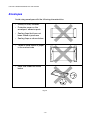
Envelopes
Avoid using envelopes with the following characteristics:
•
Glossy or shiny surfaces
•
Protective cover on the
envelopes’ adhesive parts
•
Sealing flaps that have not
been folded at purchase
•
Sealing flaps as shown below
•
Three or more layers of paper
in the marked area
•
Each side folded as shown
below
Fig. 3-2
3-10
CHAPTER 3 BEFORE WORKING WITH THE PRINTER
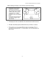
Before loading envelopes in the cassette, check the following:
•
Envelopes should have a
lengthwise sealing flap.
•
The sealing flaps should be
folded crisply and correctly
(irregularly cut or folded
envelopes may cause paper
jams).
•
Envelopes should consist of
two layers of paper in the
area circled.
Fig. 3-3
Feeding
Direction
• Envelope joints that are sealed by the manufacturer should be secure.
• All sides should be properly folded without any wrinkles or creases.
• Print quality may vary among different styles of envelopes. Prior to
purchasing large quantities, it is a good idea to test the envelopes you
plan to use.
3-11
CHAPTER 3 BEFORE WORKING WITH THE PRINTER
CAASSSSEETTTTEE FEEEEDD
The printer can feed paper from the Paper Cassette, Optional Lower Paper
Tray or Optional Legal Cassette.
Note
When you load paper into the Paper Cassette, note the following:
• If your application software supports paper size selection on the print
menu, you can select it through the software. If your application software
does not support it, you can set the paper size with the printer driver or
by using the control panel.
• The paper size has been factory set to letter for 120V models or A4 for
220/240V models. If you want to use other sizes of paper or envelopes,
change the paper size setting in PAGE FORMAT MODE, which is in
FORMAT MODE by using the control panel. For paper size selection,
see “PRINT MENU” in Chapter 4.
• If you use pre-printed paper in the cassettes, please note that the paper
should be loaded with the printed side face up and the top edge of the
paper at the back of the cassette.
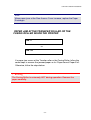
The printer automatically detects the paper size you have loaded into the
Paper Cassette. If you load a different size of paper into the paper cassette
from the size that is selected, by using the control panel or in your
application software you can change the paper size setting, the printer will
prompt you to load the correct size of paper as follows:
SIZE MISMATCH
Paper mismatch between the Printer and the
Printer Driver setting. Load Paper <size> size
into Tray <1/2>
3-12
CHAPTER 3 BEFORE WORKING WITH THE PRINTER
MAANNUUAALL FEEEEDD
Since this printer does not have a manual feed or multi purpose tray, you
cannot manually feed irregular sized paper. However, this printer has a
special “Manual Feed” mode using Tray 1 (upper tray) to accommodate
non-standard paper sizes. You can select this mode with the printer driver
or the control panel.
See “PAPER” in Chapter 4 for more information on selecting this setting
using the printer Control Panel.
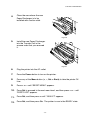
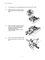
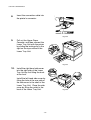
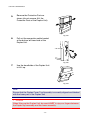
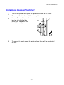
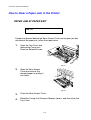
1.
When the manual feed command is selected, the printer waits until you
load the paper in Tray 1.
MANUAL FEED
=ON
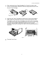
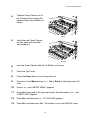
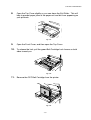
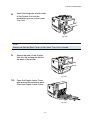
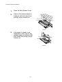
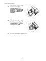
2.
Pull out Tray 1 and load the paper you are going to use. It may be
necessary to remove some or all of the paper stack first, depending on
the size of paper in the tray and the size of the paper you wish to print
on manually.
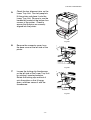
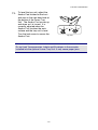
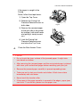
3.
Re-install Tray 1 and press Go. The printer will then start printing.
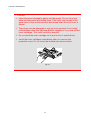
Note
• Print quality may be affected by the type of paper you use and the print
image.
• You may experience poor paper feeding during Duplex printing.
• This machine is not designed for continuous Duplex printing.
• During manual duplex printing, if you leave the printer for more than 5
minutes after the first side has been printed, the printer will reset the
function automatically.
3-13
CHAPTER 4 CONTROL PANEL OPERATION
CHAPTER 4
CONTROL PANEL OPERATION
CHAPTER 4 CONTROL PANEL OPERATION
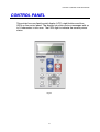
CONTROL PANEL
This printer has one liquid crystal display (LCD), eight buttons and four
LEDs on the control panel. The display can show various messages with up
to 16 characters in two rows. The LEDs light to indicate the current printer
status.
Fig. 4-1
4-1
CHAPTER 4 CONTROL PANEL OPERATION
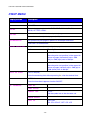
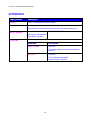
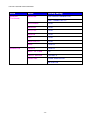
BUTTONS
You can control the basic printer operations and change various printer
settings with the 8 buttons (Go, Job Cancel, Secure Print, Reprint, +, -,
Set, Back).
K
Keeyy
Go
FFuunnccttiioonn
Exit from the control panel menu, Reprint settings
and Error messages.
Pause/Continue printing.
Job Cancel
Stop and cancel the printer operation in progress.
Secure Print
Print secure documents.
Reprint
Select the Reprint menu. (1-999)
Menu
+
Move forward through Menus.
Move forward through selectable options.
-
Move backward through Menus.
Move backward through selectable options.
Set
Select the control panel menu.
Set the selected menus and settings.
Back
Go back one level in the menu structure.
4-2
CHAPTER 4 CONTROL PANEL OPERATION
GO
OB
BU
UTTTTO
ON
N
Panel indications can be changed from their current status (MENU, ERROR
and REPRINT settings) by pressing Go once. For ERROR indications, the
panel changes only after the error is cleared.
You can PAUSE printing by pressing Go. Pressing Go again will restart the
print job and clear the PAUSE. During PAUSE, the printer is in the off-line
state.
Notes
When the printer is in PAUSE, you can choose not to print the remaining data
by pressing Job Cancel. Press Go to clear the PAUSE and return the printer
to the “READY” state.
JO
OB
AN
B CA
NC
CE
ELL B
BU
UTTTTO
ON
N
You can cancel the processing or printing of data with Job Cancel. The
display shows “JOB CANCELING” until canceling is completed. After
canceling the job, the printer returns to the “READY” state.
When the printer is in any state except receiving data or printing, the display
shows “NO DATA!!!” and you cannot cancel the job.
4-3
CHAPTER 4 CONTROL PANEL OPERATION
SEECCUURREE PRRIINNTT BBUUTTTTO
ON
N
This function makes it possible to submit a print job to the printer and have
that job print only when you interact with the printer via the control panel, or
via a web browser. This functionality allows you to print secure data to be
printed only while you are at the printer.
You can use the Secure Print function when the printer is “READY” or in the
menu state.
1.
Press Secure Print.
2.
Select the user name, job, password and print copy quantity.
3.
To start printing, press Set or Secure Print.
Notes
• The Secure Print function does not support off-line or paused printing.
• When there is no secure data and you press Secure Print, the LCD briefly
shows “NO DATA STORED.”
When you want to use the Secure Print function, refer to “Operations for
printing SECURE data” in this chapter.
4-4
CHAPTER 4 CONTROL PANEL OPERATION
REEPPRRIINNTT BBUUTTTTO
ON
N
If you want to reprint a document that has just been printed, you can reprint
it by pressing Reprint. Also, if you have created a document that you wish
to share with colleagues, simply spool the document to a non-secure area
of the printer. This document can then be re-printed by anyone who is on
the network or at the printer control panel.
You can use the Reprint function when the printer is “READY” or in the
MENU state.
When you want to print PROOF, PUBLIC or SECURE data, we recommend
installing the optional HDD or CompactFlash card.
If you do not install an HDD or CompactFlash card.
(See “COMPACTFLASH CARD/ HDD CARD” in Chapter 5.), you can
reprint from RAM. The reprint data in RAM will be deleted when the printer
is turned off.
When you use RAM to reprint:
1.
Press Set on the control panel to exit from the READY state, and then
select RAMDISK SIZE in the SETUP mode.
2.
The default RAM is 0MB. Press + to increase the reprint RAM size in
increments of 1MB.
Notes
• When you increase the RAM size for secure printing, the work area of the
printer is decreased and the printer performance is reduced. Ensure that
you reset the RAMDISK SIZE to 0MB when you have finished using
Secure Printing.
• When you store data in RAM, the data will be deleted when the printer
power is turned off.
We also recommend adding additional RAM if you want to be able to print a
large quantity of secured data. (See “RAM Expansion” in Chapter 5)
4-5
CHAPTER 4 CONTROL PANEL OPERATION
Reprinting the Last JOB
You can reprint the last print job data without sending it from the computer
again.
Notes
• When REPRINT is turned off on the panel and you press the Reprint key,
the LCD briefly shows “NO DATA STORED.”
• If you want to cancel Reprinting, press the Job Cancel key.
• If the printer does not have enough memory to spool the print job data, it
will print only the last page of the data. We recommend that you expand
the memory when you want to reprint a large amount of data. For more
information on memory expansion, see “RAM EXPANSION” of Chapter 5.
• Pressing – or + decreases or increases the number of reprint copies. You
can select between COPIES= 1 and COPIES=999.
• For more information about the settings in the printer driver, see “Job
Spooling” in Chapter 2.
4-6
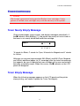
CHAPTER 4 CONTROL PANEL OPERATION
Reprint the last JOB 3 times
1.
Use the control panel to turn the REPRINT function ON in SETUP
mode.
Notes
If you are using the driver supplied with the printer, the settings for spooling
jobs in the printer driver will take priority over the settings made using the
control panel. For more information, see “Job spooling” in Chapter 2.
2.
Press Reprint.
If you wait too long to continue the control panel operation,
---REPRINT--COPIES=
1 the display will exit the REPRINT menu automatically.
Press + twice.
---REPRINT--COPIES=
3
Press Set or Reprint.
PRINTING
---REPRINT--COPIES=
1
Notes
• If you press Go, the printer will exit from the Reprint menu.
• If you want to reprint the data and have pressed Go, the display will show
“ PRESS SET TO PRINT.” Press Set to start reprinting, or press Go to
cancel the reprint job.
4-7
CHAPTER 4 CONTROL PANEL OPERATION
Printing PROOF Data
You can use this function to reprint PROOF data that has just been printed
if it has no security settings. Documents that are placed in the PROOF area
are available to anyone. This function can also be used for a document that
will be moved to a public folder at a later date.
When the area to spool data becomes full, the earliest data will be
automatically deleted first. The order of deleting data is not connected to
the order of reprinting.
When you reprint PROOF data, refer also to “Operations for printing
SECURE data” in this chapter.
Notes
• If you have not installed the optional HDD or CompactFlash, the reprint
data will be deleted when the printer is turned off.
• If there is data in the job information that cannot be displayed on the LCD,
the display shows “?”.
• For more information about the settings in the printer driver, see “Job
Spooling” in Chapter 2.
4-8
CHAPTER 4 CONTROL PANEL OPERATION
Printing PUBLIC Data
You can use this function to reprint documents stored in a PUBLIC area of
the printer memory. Documents here will not be password protected and
anyone can access them using the control panel or a web browser. The
printer will not print a PUBLIC document when you send it to the printer.
You must print using the control panel of the printer or connect to the printer
through a web browser.
Public data can be deleted using the control panel of the printer or from the
web-based management software.
When you reprint PUBLIC data, refer also to “Operations for Printing
SECURE Data” in this chapter.
Notes
• If there is data in the job information that cannot be displayed on the LCD,
the display shows “?”.
• For more information about the settings in the printer driver, see “Job
Spooling" in Chapter 2.
4-9
CHAPTER 4 CONTROL PANEL OPERATION
Printing SECURE Data
Secure documents are password protected and only those people that
know the password will be able to print the document. The printer will not
print the document when you send it for printing; to print the document you
must print using the control panel of the printer (with password) or connect
to the printer using a web browser.
If you want to delete the spooled data, you can carry out this operation
using the control panel or in the web-based management software.
Notes
• If there is data in the job information that cannot be displayed on the LCD,
the display shows “?”.
• For more information about the settings in the printer driver, see “Job
Spooling” in Chapter 2.
4-10
CHAPTER 4 CONTROL PANEL OPERATION
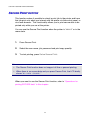
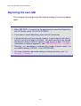
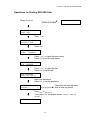
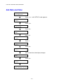
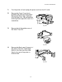
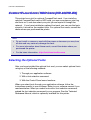
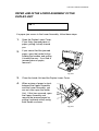
Operations for Printing SECURE Data
NO DATA STORED
Press Reprint
If there is no data.
--REPRINT-LAST JOB
Press + or -.
--REPRINT-SECURE FILE
Press Set.
SECURE FILE
USER
XXXXXX
Press + or – to select the user name.
Press Set to set the user name.
USER XXXXXX
JOB XXXXXX
Press + or – to select the job.
Press Set to set the job.
JOB XXXXXXX
PASS NO.=0000
Input your password.
Press Set to set the password
--REPRINT-COPIES=
The printer will exit this menu
after a time out period.
1
Press Set or Reprint.
If you press Go, the display shows “PRESS SET TO
PRINT.”
PRINTING
4-11
CHAPTER 4 CONTROL PANEL OPERATION
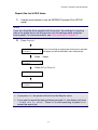
When there is no reprint data in memory
If the printer does not have reprint data in the buffer memory and you press
Reprint, the LCD shows “NO DATA STORED.”
To delete the job
Using the control panel, select the ‘DELETE STORAGE’ submenu under the
SETUP menu. Select the user name and the job to delete (you will need to
input the password to delete secure data).
To cancel the reprint job
Pressing Job Cancel allows you to cancel the current reprint job. Job
Cancel also allows you to cancel a paused reprint job.
4-12
CHAPTER 4 CONTROL PANEL OPERATION
+, – BBUUTTTTO
ON
NS
S
If you press + or – when the printer is in the on-line state (READY), it goes
off-line and the LCD will display the menu.
To display menus in the current mode
If you press + or – when the printer is in the on-line state, it goes off-line
and the LCD displays the current mode.
You can enter other menus in the current mode by pressing + or –.
Pressing + or – allows you to scroll forward or backward through the
menus and settings on the display. Press repeatedly until you access the
desired item.
To set numbers
There are two ways to input numbers. You can press + or – to scroll up or
down one number at a time, or you can hold down + or – to scroll faster.
When you see the number you want, press Set.
SEETT BBUUTTTTO
ON
N
If you press Set when the printer is in the on-line state, it goes off-line and
the LCD goes to the menu.
Pressing Set allows you to set the selected menu or number. After
changing the menu or number, an asterisk appears briefly on the right hand
side of the message.
4-13
CHAPTER 4 CONTROL PANEL OPERATION
BAACCKK BBUUTTTTO
ON
N
If you press Back when the printer is in the on-line state, it goes off-line and
the LCD goes to the menu.
Pressing Back allows you to return to the previous level from the current
menu level.
Pressing Back also allows you to select the previous digit while inputting
numbers.
When the leftmost digit is selected, Back allows you to go up one level in
the menu.
When a menu or number without an asterisk (Set not pressed) is selected,
Back allows you to return to the previous menu level with the original
setting unchanged.
Notes
When you press Set to select a setting, an asterisk appears briefly at the end
of the display. Since the asterisk indicates your selection, you can easily find
the current settings as you scroll through the display.
4-14
CHAPTER 4 CONTROL PANEL OPERATION
LEDS
The lamp lights or blinks to indicate the current printer status.
READY LED
LLE
ED
D iinnddiiccaattiioonn
M
Meeaanniinngg
On
Ready to print
Printing
Blinking
Warming up
Off
Off-line
POWER LED
LLE
ED
D iinnddiiccaattiioonn
M
Meeaanniinngg
On
The printer power is on.
Off
The printer power is off.
ALARM LED
LLE
ED
D iinnddiiccaattiioonn
M
Meeaanniinngg
On
An error has occurred in the printer.
DATA LED
LLE
ED
D iinnddiiccaattiioonn
M
Meeaanniinngg
On
Data remains in the printer buffer.
Blinking
Receiving or processing data
Off
No remaining data
4-15
CHAPTER 4 CONTROL PANEL OPERATION
LCD DISPL AY
The display shows the current printer status. When you use the control
panel, the display will change.
If you take the printer off-line, the display changes to show the selected
emulation.
If any problems occur, the display shows the corresponding error message,
maintenance message, or call service message to prompt you to take an
action. For more information about these messages, see
“TROUBLESHOOTING,” Chapter 6.
4-16
CHAPTER 4 CONTROL PANEL OPERATION
LCD MEESSSSAAG
GE
ES
S
The message on the LCD display shows the current printer status during
normal operation as shown below.
READY
!"!"#"!
K
C
M
Y
The ! marks indicate the status of the toner in the Toner Cartridges (K:
Black, C: Cyan, M: Magenta, Y: Yellow). When the ! mark blinks (#), the
indicated color toner is nearly empty. When toner becomes empty, the !
indicator disappears completely.
When an error has occurred, the type of error is displayed on the first line of
the LCD message as shown below.
The message on the second line shows information for clearing the error as
shown below.
COVER OPEN
Close the Top Cover
4-17
CHAPTER 4 CONTROL PANEL OPERATION
Printer Status messages
The following table shows the printer status messages that are displayed
during normal operation:
P
Prriinntteerr S
Meeaanniinngg
Sttaattuuss M
Meessssaaggee M
READY
Ready to print.
PROCESSING
Busy processing data.
SLEEP
In sleep status
PRINTING
Printing.
PROGRAMING-WAIT
Accessing CompactFlash card or HDD.
SELF TEST
Performing self-diagnostics.
PAUSE
The printer has suspended feeding
forms. Pressing Go resumes form feed.
NOW INITIALIZING
The printer is setting up.
WARMING UP
The printer is warming up.
RAM SIZE=xxMB
This printer has XX MB memory.
JOB CANCELLING
Cancelling the job.
RESOLUTION ADAPT
Printing with reduced resolution.
PRESS SET TO PRINT
Press Set to start printing.
RESET TO FACTORY
SETTING
The printer setting returns to the factory
setting.
4-18
CHAPTER 4 CONTROL PANEL OPERATION
HOW TO US E THE CONTROL PANEL
When you operate the Menu buttons (+, – , Set or Back), remember the
following basic steps:
• If no control panel operations are performed for 30 seconds, the LCD
automatically returns to READY.
• When you press Set to select a setting, an asterisk appears briefly at the
•
•
end of the display. After that, the display returns to the previous menu
level.
After changing the status or a setting, pressing Back before you press
Set will cause the display to return to the previous menu level with the
original settings unchanged.
There are two ways to input numbers. You can press + or – to scroll up
or down one number at a time, or you can hold down + or – to scroll
faster, the blinking digit is the changeable digit.
4-19
CHAPTER 4 CONTROL PANEL OPERATION
For example: When you want to change the “SOURCE” setting to
“TRAY1”Choose this setting to load paper always from the Tray 1.
READY
Press any of the Menu buttons (+, -, Set or Back) to turn
the printer off-line.
--MENU-INFORMATION
Press + or – to scroll forward or backward through the
menus.
--MENU-PAPER
Press Set to proceed to the next menu level.
PAPER
SOURCE
Press Set.
SOURCE
=AUTO
*
Press +.
SOURCE
=TRAY1
Press Set.
An asterisk * briefly appears at the end of the display.
The default setting is indicated by an “ *”.
SOURCE
=TRAY1
4-20
CHAPTER 4 CONTROL PANEL OPERATION
PANEL SETU P MENU
Notes
The LCD panel descriptions for the paper trays are as follows.
• Upper paper tray: Tray 1
• Optional lower tray: Tray 2
• Optional duplex unit: DX
There are 8 modes. For more information about the selections available for
each mode, refer to the pages listed below.
INFORMATION
For more information, see 4-22
PAPER
For more information, see 4-23
QUALITY
For more information, see 4-23
SETUP
For more information, see 4-24
PRINT MENU
For more information, see 4-26
NETWORK
For more information, see 4-31
INTERFACE
For more information, see 4-32
RESET MENU
For more information, see 4-33
4-21
CHAPTER 4 CONTROL PANEL OPERATION
INFORMATION
D
Diissppllaayy S
Shhoow
wss
D
Deessccrriippttiioonn
PRINT SETTINGS
Print the Configuration page.
PRINT TEST
Print a test page.
PRINT DEMO
Print the demonstration page.
PRINT FILE LIST
Print the card list.
PRINT FONTS
Print the fonts list and samples.
VERSION
Submenu
Description
SER.NO=#########
Printer serial number.
ROM VER=####
ROM firmware version
ROM DATE YY/MM/DD ROM date
Network firmware version (Network users
only)
NET VER=####
NET DATE YY/MM/DD Network Build date (Network users only)
MAINTENANCE
ENGINE VER=####
Engine Firmware version
RAM SIZE=###MB
The size of memory in this printer.
PAGE COUNTER
=######
The current total
printed pages.
IMAGE COUNTERS
C=#####, M=#####,
Y=#####, K=#####,
TOTAL=#####
The amount of
images produced
by an individual
color and the
combined Total of
all 4 colors.
REMAIN FC ROLLER
=######
REMAIN OPC BELT
=######
REMAIN FUSER
=######
REMAIN 120K KIT
=######
This is the
remaining life for
the FC roller, OPC
Belt, Fuser, 120K
Kit, PF Kit1 and PF
Kit2
REMAIN PF KIT1
=######
REMAIN PF KIT2
=######
4-22
CHAPTER 4 CONTROL PANEL OPERATION
PAPER
D
Diissppllaayy S
Shhoow
wss
D
Deessccrriippttiioonn
SOURCE
=AUTO/TRAY 1/TRAY 2
MANUAL FEED
=OFF/ON
TRAY1 SMALL
SIZE
=B5/JIS B5/COM-10/DL/EXECUTIVE
TRAY2 SMALL
SIZE
=B5/EXEC/JISB5
DUPLEX
=OFF/ON(LONG BIND)/ON(SHORT BIND)
QUALITY
D
Diissppllaayy S
Shhoow
wss
D
Deessccrriippttiioonn
HRC
=MEDIUM/DARK/OFF/LIGHT
HRC: High Resolution Control offers improved print quality of
characters and graphics that conventional laser printers cannot attain.
TONER SAVE
=OFF/ON
4-23
CHAPTER 4 CONTROL PANEL OPERATION
SETUP
D
Diissppllaayy S
Shhoow
wss
D
Deessccrriippttiioonn
LANGUAGE
= ENGLISH/FRANÇAIS /…
POWER SAVE
=ON/OFF
POWER SAVE TIME
=1 MIN:99 MIN
AUTO CONTINUE
=OFF/ON
LOCK PANEL
=OFF/ON
Turn the lock panel function ON/OFF.
PASS NO.=###
REPRINT
=ON/OFF
PAGE PROTECTION
=AUTO/OFF/LETTER/LEGAL/A4
EMULATION
=AUTO(EPSON)/AUTO(IBM)/HP LASER JET/… .
KEEP PCL
=OFF/ON
RAMDISK SIZE
=0/1/2/… MB
RESTART?
4-24
CHAPTER 4 CONTROL PANEL OPERATION
SETUP (Continued)
D
Diissppllaayy S
Shhoow
wss
D
Deessccrriippttiioonn
DELETE STORAGE
Delete the data on the CompactFlash card or HDD.
Submenu
Description
SECURE FILE
Select the User name, Job name and
password.
PUBLIC FILE
Select the User name and Job name.
PROOF FILE
Select the User name and Job name.
DATA ID (HD)
=####
DATA ID (CF)
=####
MACRO ID (HD)
=####
MACRO ID (CF)
=####
FONT ID (HD)
=####
FONT ID (CF)
=####
FORMAT ID (HD)
OK?
FORMAT ID (CF)
OK?
TIME STYLE
=YY/MM/DD hh:mm*
DATE & TIME
DISPLAY
YYYY/MM/DD hh:mm
YEAR
=YYYY
MONTH
=MM
DAY
=DD
HOUR
=hh
MINUTE
=mm
4-25
CHAPTER 4 CONTROL PANEL OPERATION
PRINT MENU
D
Diissppllaayy S
Shhoow
wss
D
Deessccrriippttiioonn
MEDIA TYPE
=PLAIN PAPER/THICK PAPER/TRANSPARENCIES
COLOR PRINT
=ON/OFF
PAPER
Set cut sheet paper size to A4, EXECUTIVE, COM-10, DL, B5,
JIS B5, LETTER, LEGAL
COPIES
You can check the total number of printed pages.
Shows the number of printed pages. (1:999)
ORIENTATION
This printer can print pages in portrait or landscape orientation.
PORTRAIT or LANDSCAPE
PRINT POSITION
This printer can be adjusted to align the page format.
Submenu
Description
X OFFSET=0
=-500:+500
Move the print start position (at the upper left
corner of pages) horizontally up to – 500
(left) to +500 (right) dots in 300 dpi.
=-500:+500
Y OFFSET=0
Move the print start position (at the upper left
corner of pages) vertically up to – 500 (up) to
+500 (down) dots in 300 dpi.
AUTO FF TIME
=OFF/1:99 (sec)
Prints the remaining data without pressing Go, after the desired time.
FF SUPPRESS
=OFF/ON
Turns the form feed suppress function ON/OFF.
HP LASERJET
FONT NO.
=I0000:#####
FONT PITCH
=###.##
SYMBOL SET
PC-8/…
Set the symbol set or the character set.
TABLE PRINT
Print code table.
AUTO LF
=OFF/ON
ON: CR!CR+LF, OFF: CR!CR
4-26
CHAPTER 4 CONTROL PANEL OPERATION
PRINT MENU (Continued)
D
Diissppllaayy S
Shhoow
wss
D
Deessccrriippttiioonn
HP LASERJET
AUTO CR
=OFF/ON
ON: LF!LF+CR, FF+CR, or VT!VT+CR
OFF: LF!LF, FF!FF, or VT!VT
AUTO WRAP
=OFF/ON
Line feed and carriage return occur when the
printer reaches the right margin.
AUTO SKIP
=ON/OFF
Line feed and carriage return occur when the
printer position reaches the bottom margin.
LEFT MARGIN
=####
Set the left margin at column 0 to 126 columns
at 10 cpi.
RIGHT MARGIN
=####
Set the right margin at column 10 to 136
columns at 10 cpi.
TOP MARGIN
=####
Set the top margin at a distance from the top
edge of the paper: 0, 0.33, 0.5, 1.0, 1.5 or 2.0”
Factory setting=0.5
BOTTOM MARGIN
=####
Set the bottom margin at a distance from the
bottom edge of the paper: 0, 0.33, 0.5, 1.0, 1.5
or 2.0”
Factory setting: 0.33(None-HP), 0.5(HP)
LINES
=####
Set the number of lines per page from 5 to 128
lines.
4-27
CHAPTER 4 CONTROL PANEL OPERATION
PRINT MENU (Continued)
D
Diissppllaayy S
Shhoow
wss
D
Deessccrriippttiioonn
EPSON FX-850
FONT NO.
=I0000:#####
FONT PITCH
=###.##
CHARACTER SET
PC-8/…
Set the symbol set or the character set.
TABLE PRINT
Print code table.
AUTO LF
=OFF/ON
ON: CR!CR+LF
OFF: CR!CR
AUTO MASK
=OFF/ON
LEFT MARGIN
Set the left margin at column 0 to 126
columns at 10 cpi.
RIGHT MARGIN
Set the right margin at column 10 to 136
columns at 10 cpi.
TOP MARGIN
Set the top margin at a distance from the
top edge of the paper: 0, 0.33, 0.5, 1.0, 1.5
or 2.0” Factory setting=0.33
BOTTOM MARGIN
Set the bottom margin at a distance from
the bottom edge of the paper: 0, 0.33, 0.5,
1.0, 1.5 or 2.0” Factory setting=0.33
LINES
Set the number of lines per page from 5 to
128 lines.
4-28
CHAPTER 4 CONTROL PANEL OPERATION
PRINT MENU (Continued)
D
Diissppllaayy S
Shhoow
wss
D
Deessccrriippttiioonn
IBM PROPRINTER
FONT NO.
=I0000:#####
FONT PITCH
=###.##
CHARACTER SET
PC-8/…
Set the symbol set and the character set.
TABLE PRINT
Print code table.
AUTO LF
=OFF/ON
ON: CR!CR+LF,
OFF: CR!CR
AUTO CR
=OFF/ON
AUTO MASK
=OFF/ON
LEFT MARGIN
Set the left margin at column 0 to 126
columns at 10 cpi.
RIGHT MARGIN
Set the right margin at column 10 to 136
columns at 10 cpi.
TOP MARGIN
Set the top margin at a distance from the
top edge of the paper: 0, 0.33, 0.5, 1.0, 1.5
or 2.0” Factory setting=0.33
BOTTOM MARGIN
Set the bottom margin at a distance from
the bottom edge of the paper: 0, 0.33, 0.5,
1.0, 1.5 or 2.0”
Factory setting: 0.33
LINES
Set the number of lines per page from 5 to
128 lines.
4-29
CHAPTER 4 CONTROL PANEL OPERATION
PRINT MENU (Continued)
D
Diissppllaayy S
Shhoow
wss
HP-GL
D
Deessccrriippttiioonn
CHAR SET(STD)
=####
CHAR SET(ALT)
=####
PEN # SIZE
PEN 1 to 6
(Set size and gray percentage for the
selected pen.)
PEN # GRAY
PEN 1 to 6
15, 30, 45, 75, 90 or 100 %
(# is the selected pen number)
BR-SCRIPT
ERROR PRINT
=OFF/ON
CAPT
=OFF/ON
CAPT: Color Advanced Photoscale
Technology offers photographic fine
grayscale on graphics. APT setting is
available only at 600 dpi.
4-30
CHAPTER 4 CONTROL PANEL OPERATION
NETWORK (Network Users Only)
D
Diissppllaayy S
Shhoow
wss
D
Deessccrriippttiioonn
TCP/IP
Submenu
Description
TCP/IP ENABLE
=ON/OFF
IP ADDRESS=
###.###.###.###
SUBNET MASK=
###.###.###.###
GATEWAY=
###.###.###.###
IP BOOT TRIES
=#
IP METHOD
=AUTO/STATIC/RARP/BOOTP/DHCP
NETWARE ENABLE
=ON/OFF
NET FRAME
=AUTO/8023/ENET/8022/SNAP
NETWARE
APPLETALK
=ON/OFF
NETBEUI
=ON/OFF
DLC/LLC
=ON/OFF
BANYAN
=ON/OFF
LAT
=ON/OFF
NETBIOS/IP
=ON/OFF
ENET
=AUTO/100B-FD/100B-HD/10B-FD/10B-HD
4-31
CHAPTER 4 CONTROL PANEL OPERATION
INTERFACE
D
Diissppllaayy S
Shhoow
wss
D
Deessccrriippttiioonn
SELECT
=AUTO/USB/PARALLEL/NETWORK
AUTO IF TIME
= 1:99 (sec)
You need to set the time out period for the auto interface selection.
INPUT BUFFER
= Level1:15
RESTART PRINTER?
Increase or decrease the
input buffer capacity.
PARALLEL
When using the parallel interface
Submenu
Description
HIGH SPEED
=ON/OFF
Turns high-speed parallel communications
ON/OFF.
=ON/OFF
BI-DIR
Turns bi-directional parallel
communications ON/OFF.
4-32
CHAPTER 4 CONTROL PANEL OPERATION
RESET MENU
D
Diissppllaayy S
Shhoow
wss
D
Deessccrriippttiioonn
RESET PRINTER
Resets the printer and restores all printer settings – including command
settings – to the settings you have previously made using the control
panel.
FACTORY RESET
Resets the printer and restores all printer default settings – including
command settings. See “List of Factory Settings”.
PARTS LIFE
Submenu
Description
FC ROLLER
Resets the Fuser Cleaner parts
life.
OPC BELT
Resets the OPC Belt parts life.
FUSER UNIT
Resets the Fixing Unit parts life.
120K KIT
Resets the 120K Kit parts life.
PF KIT1
Resets the PF Kit1 parts life.
PF KIT2
Resets the PF kit2 parts life.
4-33
CHAPTER 4 CONTROL PANEL OPERATION
Set Date and time
--MENU-INFORMATION
Press + or – until “SETUP” mode appears.
--MENU-SETUP
Press Set.
SETUP
DATE&TIME
Press Set.
DATE&TIME
YEAR
Press Set.
YEAR
=1999
*
Press +.
YEAR
=2000
Press Set.
YEAR
=2000
*
After a short time, the display changes.
DATE&TIME
YEAR
Press Set.
DATE&TIME
MONTH
DATE&TIME
2000/04/25 10:22
4-34
CHAPTER 4 CONTROL PANEL OPERATION
Set IP Address
--MENU-INFORMATION
Press +.
--MENU-NETWORK
Press Set.
NETWORK
TCP/IP
Press Set.
TCP/IP
TCP/IP ENABLE
Press +.
TCP/IP
IP ADDRESS=
Press Set.
IP ADDRESS=
192.0.0.192
*
The last digit in the first part of the number is blinking.
Press + or – to increase or decrease the number.
Press Set to go to the next digit.
IP ADDRESS=
123.0.0.192
Repeat this process until you have set your IP address.
IP ADDRESS=
123.45.67.89
Press Set to complete the IP address.
IP ADDRESS=
123.45.67.89
*
An asterisk appears at the end of the display.
4-35
CHAPTER 4 CONTROL PANEL OPERATION
About Emulation Modes
This printer has the following emulation modes:
HP LaserJet Mode
The HP LaserJet mode (or HP mode) is the emulation mode in which this
printer emulates the Hewlett-Packard LaserJet laser printer. Many software
applications support this type of laser printer. Using this mode will allow
your printer to operate at its optimum performance with those applications.
BR-Script3 Mode
BR-Script is an original Brother page description language and a
PostScript® language emulation interpreter. This printer supports level 3.
The BR-Script interpreter of this printer enables full and satisfactory control
of text and graphics on pages.
For technical information about PostScript commands, see the following
commercial manuals:
• Adobe Systems Incorporated. PostScript Language Reference Manual,
•
•
•
•
3rd Edition. Menlo Park: Addison-Wesley Publishing Company, Inc.,
1999.
Adobe Systems Incorporated. PostScript Language Program Design.
Menlo Park: Addison-Wesley Publishing Company, Inc., 1988.
Adobe Systems Incorporated. PostScript Language Reference Manual.
Menlo Park: Addison-Wesley Publishing Company, Inc., 1985.
Adobe Systems Incorporated. PostScript Language Tutorial and
Cookbook. Menlo Park: Addison-Wesley Publishing Company, Inc.,
1985.
Adobe Systems Incorporated. PostScript Language Reference Manual,
third Edition. Addison-Wesley Longman, Inc., 1999.
4-36
CHAPTER 4 CONTROL PANEL OPERATION
HP-GL Mode
The HP-GL mode is the emulation mode in which this printer emulates the
Hewlett-Packard plotter model HP-7475A. Many graphics and CAD
applications support this type of plotter. Use this mode for optimum
performance when printing from those types of applications.
EPSON FX-850 and IBM Proprinter XL Mode
The EPSON FX-850 and IBM Proprinter XL modes are the emulation
modes that this printer emulates to meet the industry-standard for dot
matrix printers of their respective manufacturers. Some applications support
these dot matrix printer emulations. Use these emulation modes for
optimum performance when printing from those types of applications.
4-37
CHAPTER 4 CONTROL PANEL OPERATION
List of Factory Settings
The following table shows the initial factory default settings.
Notes
• The settings are subject to the emulation mode. Effective modes are
indicated in parentheses in the following table.
• The following settings cannot be restored to the factory settings with the
RESET menu in the FACTORY SETTINGS mode: INTERFACE MODE,
HRC SETTING, PAGE PROTECTION, SCALABLE FONT, LOCK PANEL,
PAGE COUNTER and local language for display messages.
• The COPY setting is always restored to the factory setting when the
printer is turned off and on again.
• It is not possible to reset the NETWORK settings using the control panel. If
you want to reset the print server to its default factory settings (resetting all
information such as the password and IP address information), hold down
the Network Test button on the Network board (NC-4100h) for more than 5
seconds.
4-38
CHAPTER 4 CONTROL PANEL OPERATION
M
MO
OD
DE
E
M
ME
EN
NU
U
FFaaccttoorryy S
Seettttiinngg
PAPER
SOURCE
=AUTO
MANUAL FEED
=OFF
DUPLEX
=OFF
HRC
=MEDIUM
TONER SAVE
=OFF
LANGUAGE
=ENGLISH
POWER SAVE TIME
=30MIN
AUTO CONTINUE
=OFF
LOCK PANEL
=OFF
REPRINT
=ON
PAGE PROTECTION
=AUTO
EMULATION
=AUTO(EPSON)
KEEP PCL
=OFF
RAMDISK SIZE
=#MB
TIME STYLE
=YY/MM/DD hh:mm
MEDIA TYPE
=PLAIN PAPER
PAPER
=A4/LETTER
COPIES
=1
ORIENTATION
=PORTRAIT
PRINT POSITION
X OFFSET=0
QUALITY
SETUP
PRINT MENU
Y OFFSET=0
AUTO FF TIME
=5
FF SUPPRESS
=OFF
4-39
CHAPTER 4 CONTROL PANEL OPERATION
M
MO
OD
DE
E
M
ME
EN
NU
U
FFaaccttoorryy S
Seettttiinngg
PRINT MENU
(Continued)
HP LASERJET
FONT NO.=59
FONT PITCH/POINT=10.00/12.00
SYMBOL/CHARACTER SET=PC8
AUTO LF=OFF
AUTO CR=OFF
AUTO WRAP=OFF
AUTO SKIP=ON
LEFT MARGIN=####
RIGHT MARGIN=####
TOP MARGIN=####
BOTTOM MARGIN=####
LINES=####
FONT NO.=59
EPSON FX-850
FONT PITCH/POINT=10.00/12.00
SYMBOL/CHARACTER SET=US
ASCIF
AUTO LF=OFF
AUTO MASK=OFF
LEFT MARGIN=####
RIGHT MARGIN=####
TOP MARGIN=####
BOTTOM MARGIN=####
LINES=####
4-40
CHAPTER 4 CONTROL PANEL OPERATION
M
MO
OD
DE
E
M
ME
EN
NU
U
FFaaccttoorryy S
Seettttiinngg
PRINT MENU
(Continued)
IBM PROPRINTER
FONT NO.=59
FONT PITCH/POINT=10.00/12.00
SYMBOL/CHARACTER SET=PC8
AUTO LF=OFF
AUTO CR=OFF
LEFT MARGIN=####
RIGHT MARGIN=####
TOP MARGIN=####
BOTTOM MARGIN=####
LINES=####
CHAR SET(STD)=####
HP-GL
CHAR SET(ALT)=####
PEN # SIZE
PEN # GRAY
ERROR PRINT=OFF
BR-SCRIPT
CAPT=OFF
NETWORK
TCP/IP ENABLE=ON
TCP/IP
IP METHOD=AUTO
IP ADDRESS=192.0.0.192
SUBNET MASK=0.0.0.0
GATEWAY=0.0.0.0
IP BOOT TRIES=3
IP METHOD=AUTO
4-41
CHAPTER 4 CONTROL PANEL OPERATION
M
MO
OD
DE
E
M
ME
EN
NU
U
FFaaccttoorryy S
Seettttiinngg
NETWORK
(Continued)
NETWARE
NETWARE ENABLE=ON
INTERFACE
NET FRAME=AUTO
APPLETALK
=ON
NETBEUI
=ON
DLC/LLC
=ON
BANYAN
=ON
LAT
=ON
NETBIOS/IP
=ON
ENET
=AUTO
SELECT
=AUTO
AUTO IF TIME
=5
INPUT BUFFER
=LEVEL 3
PARALLEL
HIGH SPEED=ON
BI-DIR=ON
4-42
CHAPTER 5 MAINTENANCE
CHAPTER 5
MAINTENANCE
CHAPTER 5 MAINTENANCE
REPLACING THE CONSUMABLES
Periodically, you will need to replace the following consumables. When the
time comes to replace consumables, the following messages will appear on
the LCD panel.
The printer will stop printing when the following Operator Call Messages are
displayed:
LCD Operator Call Message
Consumable
to Replace
Approximate
Life
How to
Replace
Order
No.
TONER EMPTY X
Toner
Cartridge
12,000 pages
(Black)
See 5-5
TN-03BK
C = Cyan,
7,200 pages
(Cyan,
Magenta,
Yellow) *1
Replace the X toner cartridge
M = Magenta,
Y = Yellow,
TN-03C
TN-03M
TN-03Y
K = Black
18,000 images
Replace the waste toner pack
Waste Toner
Pack
OIL EMPTY
Oil Bottle
Fuser Cleaner
WASTE TONER
See 5-16
WT-3CL
12,000 pages
See 5-9
FO-2CL
12,000 pages
*1
See 5-13
CR-3CL
*1 *4
Replace the oil bottle
CHANGE FCR
Replace the cleaning roller
5-1
CHAPTER 5 MAINTENANCE
The following are Maintenance Messages that appear on the LCD in the
READY state. These messages provide advanced warnings to replace the
consumables before they run out. To avoid any inconvenience, you may
wish to purchase spare consumables before the printer stops printing.
LCD Operator Call Message
Consumable
to Replace
Approximate
Life
How to
Replace
Order No.
READY
Toner
Cartridge,
Black
12,000 pages
*1 *2
See 5-5
TN-03BK
Toner
Cartridge,
Cyan /
Magenta /
Yellow
7,200 pages
*1 *2
See 5-5
TN-03C
TN-03M
TN-03Y
! " " "
K C M Y
READY
" ! ! !
K C M Y
5-2
CHAPTER 5 MAINTENANCE
The following are Maintenance Messages that appear alternatively with the
“READY” message on the upper row of the LCD when the printer is in the
READY state. These messages advise you that you will need to replace
each of the consumables as soon as possible, since the consumable end of
life has been reached. The printer will continue printing when any of these
messages are displayed:
LCD Operator Call Message
Consumable
to Replace
Approximate
Life
How to
Replace
Order
No.
REPLACE FCR !"
READY
REPLACE OPC BELT
!" READY
Fuser
Cleaner
12,000 pages
*1
See 5-13
CR-3CL
OPC Belt
Cartridge
See 5-18
OP-3CL
REPLACE FUSER !"
READY
REPLACE 120K KIT
!" READY
Fusing unit
60,000
images
(Continuously
printed) *4
60,000 pages
*1
Drum
Cleaner,
Paper
Discharger,
Transfer
Roller,
Paper Pickup Roller
Separator
Pad,
Transfer
Drum
120,000
pages
See 5-27
*3
NEAR WASTE TONER
!" READY
FUSER OIL LOW !"
READY
Waste Toner
Pack
18,000
Images
See 5-16
Oil Bottle
12,000 pages
See 5-9
See 5-23
FO-2CL
Note
The Ozone Filter does not have an LCD message indicator. However, you
will need to replace it once a year.
*1 - at 5 % coverage print (A4-Letter size).
5-3
CHAPTER 5 MAINTENANCE
Note
The starter toner cartridges shipped with the printer contain only half the
normal amount of toner. (6,000 pages (Black) and 3,600 pages (Cyan,
Magenta and Yellow).
*2 - For example, if the Cyan and Magenta toner cartridges are almost
empty, the indication will be “" ! ! "” (! = blinking ")
K C M Y
If the Cyan and Magenta toner cartridges are empty, the " indicator will
have disappeared.
*3 - To replace the Paper Pick-up Roller, the Separator Pad and the
Transfer Drum, consult your local dealer/retailer or Service provider.
*4 - Definition of pages: actual output page number.
Definition of images:
if the image on a page contains only one color of either Cyan,
Magenta, Yellow or Black =>1 image, two colors => 2 images, three
colors => 3 images, four colors => 4 images.
Note
• Discard the used consumables according to local regulations. If you are
not sure of them, consult your local dealer/retailer. Be sure to re-seal the
consumables tightly so that the material inside does not spill. Do not
discard used consumables together with domestic waste.
• We recommend placing used consumables on a piece of paper or cloth
to prevent accidentally spilling or scattering the material inside.
Note
• If you use paper that is not a direct equivalent for the specified paper,
consumable and part life may be reduced.
• The Projected Life for each of the items listed is based on an average of
5% coverage of the printable area using any color toner cartridge.
Frequency of replacement will vary depending on the complexity of
printed pages, percentage of coverage and type of media used.
5-4
CHAPTER 5 MAINTENANCE
TO
ON
NE
ER
R CA
AR
RTTR
RIID
DG
GE
ES
S
! Caution
We strongly recommend using genuine Brother toner cartridges. Using
generic or refilled toner cartridges may void the warranty for this printer.
Toner Nearly Empty Message
Check printed pages, page counter, and display messages periodically. If
the " indicator starts blinking (!), the printer has nearly run out of toner or
the toner is not evenly distributed inside the cartridge.
READY
" ! ! "
K C M Y
*K stands for Black, C stands for Cyan, M stands for Magenta and Y stands
for Yellow.
Although you can print approximately 300 (Black) and 500 (Cyan, Magenta
and Yellow) additional pages (at 5% coverage) after the toner low message
first appears, be sure to replace the toner cartridge with a new one before it
becomes completely empty. When this occurs, the " indicator on the LCD
panel will disappear.
Toner Empty Message
When the following message appears on the LCD panel and the printer
stops printing, you need to replace the Toner Cartridge(s):
TONER EMPTY
5-5
CHAPTER 5 MAINTENANCE
Replacing the Toner Cartridges
! Warning
Do not put the Toner Cartridge into a fire. It could explode.
! Caution
• When replacing the Toner Cartridges, handle them carefully so that
toner does not spill.
• We strongly recommend using genuine Brother toner cartridges. Using
generic or refilled toner cartridges may void the warranty for this printer.
Note
! To ensure optimum print quality, use genuine Brother toner cartridges.
Third party toner cartridges may not work in your printer.
! To obtain genuine Brother supplies, consult the dealer where you
purchased the printer.
To replace the toner cartridge(s), follow these steps:
1. Open the Front Cover of the
printer.
Fig. 5-1
2. Remove the used Toner Cartridge(s).
3. Take the new Toner Cartridge out of the box.
5-6
CHAPTER 5 MAINTENANCE
4. After rocking each new Toner Cartridge 3 to 4 times from side to side,
remove the tape labeled ‘REMOVE’ and the orange protective cover from
the new Toner Cartridge.
Fig. 5-2
5. Insert the new Toner Cartridge(s) by positioning it in the correct guide(s).
Slide it gently into the printer. Do not try to lock or push the new Toner
Cartridge(s) in; the new Toner Cartridge(s) must rest loosely in the guide
rails, they will be correctly positioned when the front cover is closed. Note
that each color cartridge is individually keyed to prevent improper
installation. Match each cartridge color label to the corresponding label on
the printer.
Fig. 5-3
6. Close the Front Cover.
5-7
K
K
Y
Y
M
M
C
C
CHAPTER 5 MAINTENANCE
! Caution
• Insert the toner cartridge(s) gently into the printer. Do not try to lock
them into the printer by pushing them. They must stay loosely in the
guide rails so they will be correctly positioned when the front cover is
closed.
• The printer may be damaged or may not work correctly if you install
consumables other than genuine Brother supplies or if you use refilled
toner cartridges. This could void your warranty.
• Do not stand the toner cartridge on its end or turn it upside down.
• Install the toner cartridges immediately after you remove the
protective cover. Do not touch the shaded area shown below:
Fig. 5-4
5-8
CHAPTER 5 MAINTENANCE
OIILL BO
OTTTTLLE
E
Oil Bottle Low Message
When the Oil has almost run out, the following message appears on the
LCD panel. Prepare a new Oil Bottle to replace the nearly empty bottle.
After this message appears, you can print approximately 30 pages:
FUSER OIL LOW !" READY
Oil Bottle Empty Message
When the Oil completely runs out, the following message appears on the
LCD panel and the printer stops printing. When you see this message, you
must replace the Oil Bottle with a new one:
OIL EMPTY
Replace the oil bottle
5-9
CHAPTER 5 MAINTENANCE
! Warning
The Fusing Unit and the parts around it are HOT! Be sure to wait until
the Fusing Unit has cooled sufficiently before you replace the Oil
Bottle.
If you touch the HOT parts (shaded area shown below), you might get
injured.
! Caution
• Be careful not to spill oil inside the printer. It might cause considerable
damage and void your warranty. If you spill some oil, consult your
dealer or Brother authorized service representative.
• Do not loose the Oil Bottle cap. It might cause the oil to leak.
5-10
CHAPTER 5 MAINTENANCE
Replacing the Oil Bottle
1. Press the Power button to turn off the printer, and then wait until it has
cooled down sufficiently.
2. Open the Top Cover.
3. Release the Oil Bottle Lock
Levers as shown:
Fig. 5-5
4. Remove the empty Oil Bottle from the Fusing Unit. Hold a sheet of paper
under the Oil Bottle and lift it out of the Fusing Unit. Move the bottle away
from the printer to the right hand side. Be careful not to spill oil inside the
printer. It could cause considerable damage to the printer.
Fig. 5-6
5-11
CHAPTER 5 MAINTENANCE
5. Install the new Oil Bottle into the
Fusing Unit with the label facing
you. The Oil Bottle is keyed to
prevent incorrect installation.
Fig. 5-7
6. Lock the Oil Bottle Lock Levers securely.
7. Close the Top Cover.
8. Press the Power button to turn the printer On.
5-12
CHAPTER 5 MAINTENANCE
FUUSSEERR CLLEEAANNEERR
Fuser Cleaner Message
When the following message appears on the LCD panel, you will need a
replacement Fuser Cleaner Roller:
REPLACE FCR !" READY
Fuser Cleaner Change Message
When the following message appears on the LCD and the printer stops
printing, you must replace the Fuser Cleaner:
CHANGE FCR
Replace the cleaning roller
5-13
CHAPTER 5 MAINTENANCE
Replacing the Fuser Cleaner
! Warning
The Fusing unit and the parts around it are HOT! Be sure to wait until
the Fusing Unit has cooled sufficiently before replacing the Fuser
Cleaner.
If you touch the HOT parts, you might get injured.
1.
Press the Power button to turn the printer off, and then wait until it has
cooled down sufficiently.
2.
Open the Top Cover.
3.
Release the Oil Bottle Lock
Levers on both sides as shown:
Fig. 5-8
5-14
CHAPTER 5 MAINTENANCE
4.
Take the Fuser Cleaner out of
the Fusing Unit by holding the
handle of the Fuser Cleaner as
shown:
Fig. 5-9
5.
Install the new Fuser Cleaner
into the guide with the roller
side facing you.
Fig. 5-10
6.
Lock the Fuser Cleaner with the Oil Bottle Lock Levers.
7.
Close the Top Cover.
8.
Press the Power button to turn the printer On.
9.
Press any of the Menu buttons (+, – , Set or Back) to take the printer Off
Line.
10. Press + or – until “RESET MENU” appears.
11. Press Set to proceed to the next menu level, and then press + or – until
“PARTS LIFE” appears.
12. Press Set, and then press +. “FC ROLLER” appears.
13. Press Set, and then press Go. The printer is now in the READY state.
5-15
CHAPTER 5 MAINTENANCE
WAASSTTEE TO
ON
AC
NE
CK
ER
K
R PA
Approximately every 18,000 images you print at 5% coverage, you must
change the Waste Toner Pack.
NEAR WASTE TONER !" READY
Waste Toner Pack Full Message
When the Waste Toner Pack is full, the following message appears on the
LCD and the printer will stop printing. When you see this message, you
must replace the Waste Toner Pack:
WASTE TONER
Replace the waste toner pack
! Warning
Do not re-use the Waste Toner Pack.
Replacing the Waste Toner Pack
! Warning
• Do not put the Waste Toner Pack into a fire. It could explode.
• Be careful not to spill the toner. Do not inhale or allow it to get into
your eyes.
! Caution
Be careful when you handle the Waste Toner Pack so that toner will not spill
on your hands or clothes.
5-16
CHAPTER 5 MAINTENANCE
1. Open the Front Cover.
2. Remove the Waste Toner Pack
from the holder located at the
lower right side of the printer. Be
careful not to spill the toner.
Fig. 5-11
3. Peel off the sealing sticker on the
left side of the Waste Toner Pack.
Seal the opening with the sealing
sticker. See Fig. 5-12 for the
correct placement of the sticker.
When you dispose of the used
Waste Toner Pack, place it in the
plastic bag included with the
replacement Waste Toner Pack.
Please dispose of the Waste
Toner Pack in accordance with
local regulations.
Fig. 5-12
4. Insert the new Waste Toner Pack into the Waste Toner Pack Holder.
5. Close the Front Cover.
5-17
CHAPTER 5 MAINTENANCE
OPC BEELLTT CAARRTTRRIIDDG
GE
E
OPC Belt Cartridge Message
When the OPC Belt Cartridge runs out, the following message appears on
the LCD. When you see this message, you must replace the OPC Belt
Cartridge:
REPLACE OPC BELT !" READY
! Caution
• Do not touch the surface of the OPC Belt Cartridge. If you touch it, it
could degrade print quality.
• Do not expose the OPC Belt Cartridge to light (more than 800 lux) for
more than 2 minutes. This could degrade print quality. Be sure to open
the printer Front Cover BEFORE you open the Top Cover to handle the
OPC Belt Cartridge.
• Damage caused by improper handling of the OPC Belt Cartridge may
void your warranty.
5-18
CHAPTER 5 MAINTENANCE
Replacing the OPC Belt Cartridge
1.
Press the Power button and turn the printer Off.
2.
Open the Front Cover and then open the Top cover.
3.
To release the lock, pull the
green Belt Cartridge Lock
Levers on both sides toward
you.
Fig. 5-13
4.
Remove the OPC Belt
Cartridge from the printer.
Fig. 5-14
5-19
CHAPTER 5 MAINTENANCE
5.
Remove the Tension Release
Pins from both sides of the new
OPC Belt Cartridge.
Fig. 5-15
Remove the protective sheet
from the new OPC Belt
Cartridge. Do not touch the
green part of the OPC Belt
Cartridge.
Fig. 5-16
6.
Insert the new Belt Cartridge
into the printer guides with the
flat side facing you.
Fig. 5-17
7.
To lock the cartridge into the printer, press the Belt Cartridge Lock
Levers that are on both sides of the OPC Belt Cartridge to the rear.
8.
Close the Front Cover and the Top Cover.
5-20
CHAPTER 5 MAINTENANCE
9.
Press the Power button to turn the printer On.
10. Press any of the Menu buttons (+, – , Set or Back) to take the printer Off
Line.
11. Press + or – until “RESET MENU” appears.
12. Press Set to proceed to the next menu level, and then press + or – until
“PARTS LIFE” appears.
13. Press Set, and then press + until “OPC BELT” appears.
14. Press Set, and then press Go. The printer is now in the READY state.
5-21
CHAPTER 5 MAINTENANCE
OZZO
ON
NE
E FIILLTTE
ER
R
Ozone Filter
You will need to replace the Ozone Filter once a year to prevent ozone from
coming out of the printer.
! Caution
You must replace the Ozone Filter once a year. If you do not, it might cause
a noticeable odor of Ozone.
Replacing the Ozone Filter
1. Slide and remove the Rear Side
Cover.
Fig. 5-18
2. Remove the Ozone Filter Case
from the Rear Side Cover.
Fig. 5-19
3. Insert the new Ozone Filter Case into the Rear Side Cover.
4. Reinstall the Rear Side Cover by sliding it into place.
5-22
CHAPTER 5 MAINTENANCE
FUUSSIINNG
NIITT
G UN
Fusing Unit
When the following message appears on the LCD panel, you must replace
the Fusing Unit:
REPLACE FUSER !" READY
! Warning
The Fusing Unit and the parts around it are HOT! Be sure to wait until
the Fusing Unit has cooled down sufficiently before replacing the
Fusing Unit.
If you touch the HOT parts, you might get injured.
! Warning
After replacing the Fusing Unit, wait for approximately 30 minutes
before you print to allow the fusing oil to circulate.
5-23
CHAPTER 5 MAINTENANCE
Replacing the Fusing Unit
1.
Press the Power button to turn off the printer. Unplug the printer. To
avoid injury, wait until the printer has cooled down sufficiently before you
replace the Fusing Unit.
2.
Open the Top Cover.
3.
Unscrew the two long screws
as shown to release the Fusing
Unit from the printer.
Fig. 5-20
Note
If you begin using a new Fusing Unit immediately, poor print quality may
result. Please wait for 30 minutes after installing a new Fusing Unit to
allow the oil to circulate completely through to the Heat Roller.
4.
Hold the handles on both sides
as you remove the Fusing Unit
from the printer.
Fig. 5-21
5-24
CHAPTER 5 MAINTENANCE
! Caution
When removing the Fusing Unit from the printer, be sure to keep the Fusing
Unit flat, so oil will not spill. Considerable damage can occur if oil is spilled
inside the printer.
5.
Remove the Oil Bottle and the Fuser Cleaner from the Fusing Unit.
6.
Install the new Fusing Unit into
the printer. Be sure to insert the
Fusing Unit completely into the
printer.
Fig. 5-22
7.
Secure the Fusing Unit with the
two long screws.
Fig. 5-23
8.
Install the Fuser Cleaner and the Oil Bottle into the new Fusing Unit, and
then lock the Oil Bottle Lock Levers. Be careful not to spill oil inside the
printer. This could damage the printer.
9.
Close the Top Cover.
10. Plug the printer into the AC outlet.
5-25
CHAPTER 5 MAINTENANCE
Note
If the condition of the Fuser Cleaner is poor, we recommend that you replace
the Fuser Cleaner at the same time as the Fusing Unit. The life counter for
the Fuser Cleaner will also need to be reset. Please refer to page 5-15 for
instructions.
Partially used Oil Bottles can be reused with a new Fusing Unit.
Please wait for 30 minutes after installing a new Fusing Unit to allow
the oil to circulate completely through to the Heat Roller.
11. Press the Power button to turn on the printer.
12. Press any of the Menu buttons (+, – , Set or Back) to take the printer Off
Line.
13. Press + or – until “RESET MENU” appears.
14. Press Set to proceed to the next menu level, and then press + or – until
“PARTS LIFE” appears.
15. Press Set, and then press + until “FUSER UNIT” appears.
16. Press Set, and then press Go. The printer is now in the READY state.
! Caution, Warning
Please be careful when replacing the Fusing Unit. Do not put pressure on
the Fusing Unit; it should fit in easily. If it does not, make sure the Fusing
Unit connector is free to move.
Do not apply force! It could damage both the Fusing Unit and the printer.
5-26
CHAPTER 5 MAINTENANCE
120K KIITT
120K Kit
When you see the following message on the LCD, you must replace the
items located in the 120K Kit, which includes the Drum Cleaner, Paper
Discharger, Transfer Roller, Paper Pick-up Roller, Separator Pad and
Transfer Drum.
Note
• User replacement of some of the following 120K Kit parts is not
recommended.
• For user replacement of the Drum Cleaner, Paper Discharger and
Transfer Roller, please refer to the instructions found below.
• We recommend that you contact your local Brother Authorized Dealer or
Service Center for replacing the Paper Feeding Roller, Separator Pad
and Transfer Drum.
• We recommend that you contact your Service provider when you see
the following message on the LCD panel:
REPLACE 120K KIT !" READY
5-27
CHAPTER 5 MAINTENANCE
Drum Cleaner
! Caution
Both ends of the Drum Cleaner roller consist of metal bearings that connect
the bias element to the power supply. These must be connected correctly
when you install the Drum Cleaner. Be sure to check how to connect these
correctly by referring to the old Drum Cleaner before you begin replacement.
Replacing the Drum Cleaner
1.
Press the Power button to turn the printer Off.
2.
Open the Top Cover.
3.
Remove the Drum Cleaner Cover.
Fig. 5-24
4.
Remove the Drum Cleaner by
holding the left and right hand
sides and lift it upwards.
Fig. 5-25
5-28
CHAPTER 5 MAINTENANCE
5.
Clean the area where the new
Drum Cleaner is to be installed
with a cotton cloth.
Fig. 5-26
6.
Install the new Drum Cleaner into
the printer by gently placing the
brass bearings into the guides,
and then pushing the handle
down until the bearings click into
place. Ensure that the Drum
Cleaner is free to move slightly
upwards (rotating slightly around
the bearings) in the housing after
you have installed it.
Fig. 5-27
7.
Re-install the Drum Cleaner Cover, and then close the Top Cover.
8.
Plug the printer into the AC outlet.
9.
Press the Power button to turn on the printer.
10. Press any of the Menu buttons (+, – , Set or Back) to set the printer Off
Line.
11. Press + or – until “RESET MENU” appears.
12. Press Set to proceed to the next menu level, and then press + or – until
“PARTS LIFE” appears.
13. Press Set, and then press + until “120K KIT” appears.
14. Press Set, and then press Go. The printer is now in the READY state.
5-29
CHAPTER 5 MAINTENANCE
Paper Discharger
! Caution
Do NOT touch the charging wire!
Fig. 5-28
Replacing the Paper Discharger
1.
Press the Power button to turn the printer Off.
2.
Open the Rear Access Cover.
3.
Remove the Paper Discharger
from the Transfer Unit by lightly
pressing it down and then sliding
it to the right to release it from
the catches. Hold the right
handside of the Discharging Unit
and lift it up to remove it.
Fig. 5-29
5-30
CHAPTER 5 MAINTENANCE
4.
Clean the area where the new
Paper Discharger is to be
installed with a cotton cloth.
Fig. 5-30
5.
Install the new Paper Discharger
into the Transfer Unit in the
reverse order that you removed
it.
Fig. 5-31
6.
Plug the printer into the AC outlet.
7.
Press the Power button to turn on the printer.
8.
Press any of the Menu button (+, – , Set or Back) to take the printer Off
Line.
9.
Press + or – until “RESET MENU” appears.
10. Press Set to proceed to the next menu level, and then press + or – until
“PARTS LIFE” appears.
11. Press Set, and then press + until “120K KIT” appears.
12. Press Set, and then press Go. The printer is now in the READY state.
5-31
CHAPTER 5 MAINTENANCE
Replacing the Transfer Roller
1.
Press the Power button to turn the printer Off.
2.
Open the Rear Access Cover.
3.
Release the Transfer Roller Lock
Levers on the right and left hand
sides, and then lift the Levers to
release the Transfer Roller.
Fig. 5-32
4.
Remove the Transfer Roller by
gently pulling the right handside up.
Slide the Transfer roller to the right
to remove it.
Fig. 5-33
5-32
CHAPTER 5 MAINTENANCE
5.
Install the new Transfer Roller by
holding the Lock Levers of the
Transfer Roller and adjusting the
angle of the Transfer Roller Lever
shafts (both sides) to match the
Transfer Unit groove. Set the
Transfer Roller onto the shafts and
place the Roller onto the springs as
shown below:
Fig. 5-34
Lock Levers
Transfer Roller Shaft
Spring
Fig. 5-36
Fig. 5-35
6.
Push down the Lock Lever to lock the Transfer Roller into place.
7.
Close the Rear Access Cover.
8.
Plug the printer into the AC outlet.
9.
Press the Power button to turn on the printer.
5-33
CHAPTER 5 MAINTENANCE
Note
• User replacement of some of these parts is not recommended.
• For replacement of the Paper Pick-up Roller, Separator Pad and the
Transfer Drum, consult your local dealer/retailer.
• Actions 10 to 14 should only be carried out by your dealer or
Brother Authorized Service Center when they have replaced the
Paper Pick-up Roller, Separator Pad and the Transfer Drum.
• Replacement of only the Paper Discharger and the Transfer Roller
is not a full 120K service and the counter should not be reset until
these additional parts are replaced.
10. Press any of the Menu buttons (+, – , Set or Back) to take the printer Off
Line.
11. Press + or – until “RESET MENU” appears.
12. Press Set to proceed to the next menu level, and then press + or – until
“PARTS LIFE” appears.
13. Press Set, and then press + until “120K KIT” appears.
14. Press Set, and then press Go. The printer is now in the READY state.
5-34
CHAPTER 5 MAINTENANCE
CLEANING THE PRINTER
Periodically, clean the printer exterior and interior with a dry soft cloth. If
printed pages are stained with toner, clean the printer interior with a dry soft
cloth.
We recommend cleaning the Paper Guide, Registration Roller and Exit
Roller every 20,000 printed pages or every 12 months.
Cleaning the Printer Exterior
Clean the printer exterior as follows:
1.
Turn off the printer and unplug the power cord.
2.
Remove the Paper Cassette from the printer.
3.
Wipe the printer body with a soft cloth to remove dust. Dip the cloth in
water and wring it out thoroughly for cleaning.
Note
Use water for cleaning. Cleaning with volatile liquids such as thinner or
benzine will damage the surface of the printer.
Do not use cleaning materials that contain ammonia. They could damage the
printer, particularly the toner cartridges
Fig. 5-37
5-35
CHAPTER 5 MAINTENANCE
4.
Clean the Paper Guide with a dry soft cloth. If paper and foreign objects
are stuck in the Paper Cassette, remove them.
Fig. 5-38
5.
Install the Paper Cassette into the printer.
6.
Plug the power cord into the AC outlet, and then turn on the printer.
Periodic Printer Cleaning
Note
When you clean the printer interior, pay attention to the following:
• If your clothes are smeared with toner, wipe off the toner with a dry cloth
and immediately wash the clothes in cold water to avoid stains.
• The Fusing Unit and the parts around it are HOT! Never touch the
shaded areas shown below.
• Never touch or clean the Transfer Roller because print quality may be
adversely affected.
• Be careful not to inhale the toner.
5-36
CHAPTER 5 MAINTENANCE
Clean the printer interior as follows:
1.
Turn off the printer and unplug the power cord.
2.
Open the Rear Access Cover.
3.
Clean the Registration Roller and the Paper Pick-up Roller with a dry
soft cloth to prevent paper jams.
Fig. 5-39
! Caution
Be sure not to break the Actuator while cleaning the Paper Pick-up Roller.
Fig. 5-40
5-37
CHAPTER 5 MAINTENANCE
4.
Remove the Paper Discharger from the Transfer Unit.
Fig. 5-41
5.
Clean the Paper Discharger Case Housing with a dry cotton cloth.
Clean the Corona Wire and the inside of the Paper Discharger Case
with a dry cotton swab.
Fig. 5-42
6.
Re-install the Paper Discharger into the Transfer Unit.
! Caution
• Do not break the vinyl string on top of the Paper Discharger Case while
cleaning the Paper Discharger.
• Do not break the Corona Wire.
7.
Close the Rear Access Cover.
5-38
CHAPTER 5 MAINTENANCE
8.
Open the Top Cover slightly so you can clean the Exit Roller. This will
help to prevent paper jams at the paper exit and dirt from appearing on
your printouts.
Fig. 5-43
9.
Open the Front Cover, and then open the Top Cover.
10. To release the lock, pull the green Belt Cartridge Lock Levers on both
sides toward you.
Fig. 5-44
11. Remove the OPC Belt Cartridge from the printer.
Fig. 5-45
5-39
CHAPTER 5 MAINTENANCE
! Caution
• Do not touch the OPC Belt surface with bare hands or gloves.
• If the Belt is exposed for more than two minutes to a light source of 800
lux, the Belt may be damaged.
12. Clean the OPC Belt Cartridge and the OPC Belt Cartridge Case with a
dry cotton cloth.
Fig. 5-46
13. Clean the Corona Wire. Remove any toner on the Corona Wire with the
Corona Wire Cleaner supplied with the Corona Case by sliding the
Corona Wire Cleaner gently from left to right.
Fig. 5-47
! Caution
• Do not break the Corona Wire.
• Place the Corona Wire Cleaner back to the original position after
cleaning the Corona Wire.
5-40
CHAPTER 5 MAINTENANCE
14. Remove all the Toner Cartridges from the printer.
15. Use the fingers of both hands to hold the two knobs on the Dustproof
Glass, and then remove it from the Laser Unit by lifting it up.
Fig. 5-48
16. Clean the surface of the Dustproof Glass with a dry cotton swab.
Fig. 5-49
17. Re-install the Dustproof Glass by aligning the ▲ marks on the Laser Unit
and the Dustproof Glass; This will ensure that it is correctly in place and
cannot move.
Fig. 5-50
5-41
CHAPTER 5 MAINTENANCE
18. Re-install all the Toner Cartridges and the OPC Belt Cartridges.
19. Close the Front Cover and the Top Cover.
! Caution
• NEVER use Alcohol or other similar solvents for cleaning the dustproof
glass, otherwise it will be a cause of image failure.
5-42
CHAPTER 5 MAINTENANCE
REPACKING AND RELOCATING THE
PRINTER
! Warning
• Whenever you transport the printer ALWAYS use the packing
materials that were provided with your printer. Follow the steps
detailed below to re-pack the printer or the printer may be
damaged. This will void the printer’s warranty.
• Before you ship or move the printer, be sure to take out the following
items and place them in separate bags (do not place them in the printer
carton):
* Fusing Unit
* Waste Toner Pack
* Toner Cartridges
* OPC Belt Cartridge
• Remove the Oil Bottle, and then use the syringe supplied with the printer
to remove Oil from the Fusing Unit tray. Using a cloth, wipe up any
remaining oil that cannot be removed with the syringe as shown in Fig.
5-51.
• Discard the oil according to local regulations.
Fig. 5-51
5-43
CHAPTER 5 MAINTENANCE
How to Repack the Printer
1.
Press the Power button to turn the printer off. Unplug the printer.
2.
Remove the Waste Toner Pack, Toner Cartridges, Fusing Unit and
OPC Belt Cartridge from the printer. Place them in their original
packaging. Do not place them together with the printer in the
printer carton.
3.
Place the printer in its original packing material and in the original
carton.
4.
Close the carton and tape it securely.
5-44
CHAPTER 5 MAINTENANCE
OPTIONS
LO
OW
RA
NIITT (LT-26CL)
WE
AY
ER
Y UN
R TR
Loading Paper from the Lower Paper Cassette
The lower tray unit is a device that functions as a second paper source. It
can hold a maximum of 500 sheets of paper (75 g/m2 or 20 lbs). To
purchase the optional lower tray unit, please consult the dealer where you
purchased the printer.
With the lower tray unit installed, load paper into the lower paper cassette
the same way you load paper in the upper media cassette.
How to Install the Lower Tray Unit
! Warning
This printer is heavy and weighs approximately 39kg (86 lbs). To avoid
injury when moving or lifting this printer, be sure to use at least two
people.
When you lift the printer be sure to use the handholds located at the
bottom four corners of the printer.
! Caution
When moving or lifting this printer, be sure to keep the printer flat. To avoid
spills, you must first remove the Toner Cartridges, Waste Toner Pack, Oil
Bottle and Fusing Unit.
5-45
CHAPTER 5 MAINTENANCE
1.
Turn the printer off and unplug the power cord from the AC outlet.
2.
Place the Lower Tray Unit on a flat
table, and then remove the protective
parts.
Fig. 5-52
3.
Pull out the Paper Cassette from the
Lower Tray Unit, and then remove
the tapes and the protective parts
inside of the Cassette.
Install the Paper Cassette into the
Lower Tray Unit.
Fig. 5-53
4.
Pull out the connection cable located
at the left rear side of the Lower Tray
Unit.
Fig. 5-54
5-46
CHAPTER 5 MAINTENANCE
5.
Check the two alignment pins on the
Lower Tray Unit. Use two people to
lift the printer and place it onto the
Lower Tray Unit. Be sure to use the
handholds located at the bottom four
corners of the printer. Check to
ensure that the pins are correctly
aligned into the printer.
Fig. 5-55
6.
Remove the connector cover from
the base cover at the left side of the
printer.
Fig. 5-56
7.
Loosen the locking clip thumbscrew
on the left side of the Lower Tray Unit
by rotating it counterclockwise.
Rotate the locking clip and hook it
onto the printer so that it hangs
down, and then secure it with the
thumbscrew.
Fig. 5-57
5-47
CHAPTER 5 MAINTENANCE
8.
Insert the connection cable into
the printer’s connector.
Fig. 5-58
9.
Pull out the Upper Paper
Cassette, and then connect the
Lower Tray Unit with the printer
by sliding the locking clip to the
right on the top surface of the
Lower Tray Unit.
Fig. 5-59
10. Install the right hand side cover
into the right side of the Lower
Tray Unit by first fitting the hook
at the front.
Install the left hand side cover by
fitting the hole at the rear side of
the side cover to the shaft of the
Lower Tray Unit. Close the side
cover by fitting the notch to the
hook of the Lower Tray Unit.
5-48
Fig. 5-60
CHAPTER 5 MAINTENANCE
11. To level the tray unit, adjust the
Anchor Feet located at the front
and rear on the right hand side at
the bottom of the Lower Tray
Unit. The Anchor Foot moves up
and down as it is turned. It is
correctly adjusted when the
Anchor Foot touches the work
surface and the tray unit is level.
Turn the lock screw to secure the
Anchor Foot.
Fig. 5-61
Note
Do not load Transparencies, Labels and Envelopes in the cassette
installed into the optional Lower Tray Unit. It may cause paper jams.
5-49
CHAPTER 5 MAINTENANCE
DUUPPLLEEXX UNNIITT (DX-2600)
The following paper sizes can be used for the Duplex Unit:
A4, Letter, B5 (JIS/ISO), Legal, Executive
How to Install the DUPLEX Unit
! Warning
• This printer is heavy and weighs approximately 39kg (86 lbs). To
avoid injury when moving or lifting this printer, be sure to use at
least two people.
• When you lift the printer be sure to use the handholds located at
the bottom four corners of the printer.
! Caution
When moving or lifting this printer, be sure to keep the printer flat. To avoid
spills, you must first remove the Toner Cartridges, Waste Toner Pack, Oil
Bottle and Fusing Unit.
Note
• The Lower Tray Unit must be connected before installing the Duplex
Unit.
• When you do maintenance on the printer, first open the Duplex Top
Cover Assembly.
• When you want to open the Rear Access Cover of the printer, open the
Duplex Lower Cover and the inside unit.
5-50
CHAPTER 5 MAINTENANCE
1.
Turn the printer off and unplug the power cord from the AC outlet.
2.
Remove the Fuser Cover that is
located at the rear top of the printer.
Remove the Rear Caps (2 pieces)
from the fuser unit. We recommend
removing those caps with a coin or a
screwdriver.
Fig. 5-62
3.
Remove the left handside cover of
the Lower Tray Unit.
Fig. 5-63
4.
Remove the Back caps (2 pieces) of
the Lower Tray Unit. Push down
lightly on the caps and then slide
them to the rear of the printer to
remove them.
Fig. 5-64
5-51
CHAPTER 5 MAINTENANCE
5.
Remove the Protective Parts as
shown (do not remove ALL the
Protective Parts of the Duplex Unit).
Fig. 5-65
6.
Pull out the connection cable located
at the bottom left hand side of the
Duplex Unit.
Fig. 5-66
7.
Use the handholds of the Duplex Unit
to lift it up.
Fig. 5-67
Note
Ensure that the Duplex Cover Top Assembly is correctly aligned and latched
with the lower part of the Duplex Unit
! Caution
When lifting up the Duplex Unit, be careful NOT to nip your fingers between
the Duplex top assembly and the lower assembly.
5-52
CHAPTER 5 MAINTENANCE
8.
Insert the fixing pins at both sides
of the Duplex Unit into the
installation grooves in the Lower
Tray Unit.
Fig. 5-68
Note
Make sure that the Rear Cover of the Lower Tray Unit is closed.
9.
Secure the pawl of the Duplex
Unit into the rectangular hole in
the back of the printer.
Fig. 5-69
10. Open the Duplex Lower Cover
and remove the protective parts.
Close the Duplex Lower Cover.
Fig. 5-70
5-53
CHAPTER 5 MAINTENANCE
11. Open the Inside Unit to remove
the protective parts and close
the Inside Unit.
Fig. 5-71
12. Open the Duplex Cover Top
Assembly and remove the
protective parts from the
Duplex Cover Top Assembly
Fig. 5-72
13. Securely connect the Duplex
Unit and the Printer with the
thumbscrews (2 pieces).
Fig. 5-73
5-54
CHAPTER 5 MAINTENANCE
14. Connect the connector cable to
the upper connector on the
printer.
Fig. 5-74
15. Fit the left hand side cover of
the Lower Tray Unit to the
Lower Tray Unit.
Fig. 5-75
16. Plug in the printer and turn the
printer on.
Fig. 5-76
5-55
CHAPTER 5 MAINTENANCE
CO
OM
MP
PA
AC
CTTFLLA
AS
SH
H CA
AR
RD
D / HDD CA
AR
RD
D (HD-6G/HD-EX)
This printer has a slot for optional CompactFlash card. If you install an
optional CompactFlash card or HDD card, you can save macros, print log
and fonts on it, and also select your print job and reprint it through the
network. If you have installed an optional font card, you can use the fonts
stored in it as well as the resident fonts. For optional font cards, consult the
dealer where you purchased the printer.
Note
• Do not install or remove a card with the power on because you may lose
all data and may seriously damage the card.
• For more information about these cards, consult the dealer where you
purchased the printer.
• For the latest information: http://solutions.brother.com
Selecting the Optional Fonts
After you have installed the optional font card, you can select optional fonts
using any of the following methods:
1. Through your application software
2. With a font selection command
3. With the Control Panel menu functions.
When you select fonts through your application software, follow the
instructions specific to your software. Refer to your software manual if you
need assistance. When you select fonts with a font selection command,
embed the font selection command in your program. See the Technical
Reference Manual, which is optionally available for this printer.
5-56
CHAPTER 5 MAINTENANCE
Note
When you select the fonts through your software or with a command, note
the following:
• You do not need to be concerned about the Font control panel setting.
The software or command overrides the printer setting.
• Be sure to install a font card that has your desired fonts. The printer
automatically selects the font that has exactly the same or similar
characteristics as those you have set through the software or with a
command. If the installed font card does not happen to have a font of
similar characteristics, the printer will print in an unexpected font.
To select fonts with the Control Panel setting menu, follow these basic
steps:
1.
Press any of the Menu buttons (+, – , Set or Back) to take the printer Off
Line.
2.
Press + or – until “INFORMATION” appears on the LCD display.
3.
Press Set to proceed to the next menu level, and then press + or – until
“PRINT FONTS” appears.
4.
Press Set to print the list of optional fonts (Fig. 5-77).
5.
Find the Font Number on the list.
5-57
CHAPTER 5 MAINTENANCE
Font Number
Fig. 5-77
6.
Use + or – on the Control Panel to select “PRINT MENU.” .
7.
Press Set to proceed to the next menu level, and then press + or – to
select: “HP LASERJET”, “EPSON FX-850”, or “IBM PROPRINTER” .
8.
Press the Set key to select the Emulation for the fonts you want to
select; “HP LASERJET”, “EPSON FX-850”, or “IBM PROPRINTER”
9.
Use + or – key to select “FONT NO,” , and then select the Font Number
of the font you want.
5-58
CHAPTER 5 MAINTENANCE
Installing a CompactFlash Card
1.
Turn off the printer and unplug the power cord from the AC outlet.
Disconnect the interface cable from the printer.
2.
Insert a CompactFlash card
into the slot with the label
facing you. Make sure it is
inserted correctly.
Fig. 5-78
3.
To remove the card, power the printer off and then pull the card out of
the slot.
5-59
CHAPTER 5 MAINTENANCE
Installing a HDD (Hard Disk Drive)
1.
Turn off the printer and unplug the power cord from the AC outlet.
Disconnect the interface cable from the printer.
2.
Unscrew the two screws
securing the rear plate of the
main controller board and pull
out the main controller board.
Fig. 5-79
3.
Insert the 4 shoulder screws
supplied with the HD-6G/HDEX unit into the bottom of the
HD-6G/HD-EX.
Fig. 5-80
4.
Connect the shorter Hard disk
cable to the HD-6G/HD-EX with
the keyed side upwards,
ensuring that it is correctly
aligned.
Fig. 5-81
5-60
CHAPTER 5 MAINTENANCE
5.
Fit the 4 HD-6G/HD-EX
shoulder screws into the 4
holes of the main controller
board, and then secure the
shoulder screws with the
screws provided from the rear
of the PCB.
Fig. 5-82
6.
Connect the flat cable to the
main controller board.
Fig. 5-83
7.
Install the main controller board
into the printer by sliding it into
the guide rails.
Fig. 5-84
5-61
CHAPTER 5 MAINTENANCE
8.
Secure the main controller board with the 2 screws.
9.
Reconnect the interface cable to the printer. Plug the power cord into
the AC outlet, and then turn on the printer.
10. Format the HD-6G/HD-EX from the control panel. See Chapter 4 for
details.
5-62
CHAPTER 5 MAINTENANCE
RAM EXXPPAANNSSIIO
ON
N
This printer has 64 Mbytes of standard memory and 3 slots for optional
expansion memory. The memory can be expanded by 384 Mbytes by
installing commercially available dual in-line memory modules (DIMMs).
(The standard memory fitted can vary depending on the printer model and
the country.)
This printer uses memory modules that are:100 pins, no-parity, SDRAM with 64Mbit or more.
This printer is not compatible with Extended Data Output (EDO) DIMM, or
DIMM that uses 16Mbit SDRAM.
The following capacity of DIMM can be installed:
<Europe>
• 16 Mbyte
• 32 Mbyte
• 64 Mbyte
• 128 Mbyte
BUFFALO
BUFFALO
BUFFALO
BUFFALO
<US>
• 16 Mbyte
• 32 Mbyte
• 64 Mbyte
• 128 Mbyte
TECHWORKS
TECHWORKS
TECHWORKS
TECHWORKS
TECHNOLOGY
TECHNOLOGY
TECHNOLOGY
TECHNOLOGY
12323-0001
12324-0001
12325-0001
12326-0001
12456-0001
12457-0001
12458-0001
12459-0001
In general, the DIMM must have the following specifications:
Type:
CAS Latency:
Clock Frequency:
Capacity:
Height:
Parity:
Dram Type:
100 pin and 32 bit output
2
66Mhz or more
16,32,64 or 128 Mbyte
46mm (1.8 inches) or less
NONE
64 M bit SDRAM 4 Bank SDRAM can be used.
5-63
CHAPTER 5 MAINTENANCE
Note
• There might be some DIMMs that will not work with this printer.
• For more information, consult the dealer where you purchased the
printer.
• For the latest information: http://solutions.brother.com
To install DIMMs, follow these steps:
1.
Turn off the printer and unplug the power cord from the AC outlet.
Note
Be sure to turn off the power to the printer before installing or removing the
DIMMs.
2.
Unscrew the two screws
securing the rear plate of the
main controller board, and then
pull out the main controller
board.
Fig. 5-85
3.
Unpack the DIMM and hold it by its edges.
! Caution
Do not touch the memory chips and the surface of the main controller
board. If static electricity collects, it may damage these electrical parts.
5-64
CHAPTER 5 MAINTENANCE
4.
5.
Hold the DIMM with your
fingers on the side edges and
your thumb against the back
edge. Align the notches on the
DIMM with the DIMM slots.
(Check that the locks on each
side of the DIMM slot are open,
or outward.)
Fig. 5-86
Press the DIMM straight into the slot (press firmly). Make sure the locks
on each side of the DIMM snap inward into place. (To remove a DIMM,
the locks must be released.)
Note
• When you install less than two DIMMs, be sure to install them in the
order Slot 1, Slot 2 and then Slot 3.
• When you install different capacities of DIMMs, be sure to install the
larger capacity DIMM in Slot 1 and the smaller capacity DIMM in Slot 2
and then Slot 3.
6.
Refit the main controller board
into the printer by sliding it into
the guide rails.
Fig. 5-87
7.
Secure the main controller board with the two screws.
8.
Reconnect the printer cable from your computer. Plug the power cord
into the AC outlet and turn on the printer.
9.
To check whether the DIMM has been installed correctly, you may
perform a Test Print “Print Configuration” that will print the current
memory size.
5-65
CHAPTER 6 TOURBLE SHOOTING
CHAPTER 6
TROUBLESHOOTING
CHAPTER 6 TROUBLE SHOOTING
TROUBLES HOOTING
If any problems occur, the printer automatically stops printing, diagnoses
the problem, and displays the resulting message to alert you. Take the
appropriate action, referring to the following tables. If you cannot clear the
problem, consult the dealer where you purchased the printer. Inform the
dealer of the message number for quick troubleshooting.
ERRRRO
ES
SS
OR
SA
R ME
AG
GE
ES
S
When any one of the following messages appears, the printer will stop
operating.
Error Message
Remarks
TONER EMPTY X
X = C, M, Y, K,
Replace the X toner cartridge
NO TONER X
X = C, M, Y, K,
Install the X toner cartridge
COVER OPEN
Close the Front Cover
COVER OPEN
Close the Top Cover
COVER OPEN
Close the Rear Access Cover
COVER OPEN
Close the Lower Feeder Unit Cover
COVER OPEN
Close the Duplex Unit Cover
JAM X
Refer to the diagram, and check the location. Remove the
jammed paper.
NO PAPER T1/2
Load paper into Tray 1/2.
WASTE TONER
Replace the waste toner pack.
OIL EMPTY
Replace the oil bottle.
6-1
X = A1, A2, B, C, D, E1,
or E2
CHAPTER 6 TROUBLE SHOOTING
Error Message
Remarks
CHANGE FCR
Replace the cleaning roller.
NO OPC BELT
Install the OPC belt.
NO FC ROLLER
Install the cleaning roller.
NO LFU
When the Duplex Unit is
installed.
Install the lower tray unit.
NO TR ROLLER
Install the transfer roller.
ILLEGAL TONER
Use only Brother genuine toner cartridge.
NO TRAY 1/2
The indicated paper tray was not detected. Install it, or
ensure that it is inserted correctly.
SIZE ERROR T1/2
Specify the correct paper size for the indicated tray.
SIZE ERROR DX
The duplex unit can print only in the sizes specified. Specify
the correct paper size.
STACKER FULL
Remove the paper from the output tray.
MEDIA MISMATCH
Media mismatch between the Printer and the Printer Driver
setting. Load XX into Tray <1/2>.
XX = Plain Paper,
Transparencies, Thick
Paper
SIZE MISMATCH
Paper mismatch between the Printer and the Printer Driver
setting. Load Paper <size> size into Tray <1/2>
MANUAL FEED
Load paper <size> into Tray1, and then press GO.
MEDIATYPE ERROR
XX = T1, T2 or DX
Specify the correct media type: XX
XX=T1, T2, or DX
NO FUSING UNIT
A fusing unit was not detected. Please install one.
CARD ERROR
An error occurred when accessing the Flash card. Check
that the driver is formatted and not in Write Protect mode.
6-2
CHAPTER 6 TROUBLE SHOOTING
Error Message
Remarks
HDD ERROR
An error occurred when accessing the HDD. Power cycle
the printer and check that it is formatted.
DIMM ERROR
Ensure that the DIMM is installed correctly.
CARD REMOVAL
The Flash card was removed while the printer was powered
on. Power cycle the printer.
BUFFER ERROR
Check the cable connection between the computer and the
printer.
STORAGE FULL
There is not enough space on the Hard Disk.
STORAGE FULL
The RAMDISK SIZE is set to 0MB or there is no more space
to store jobs.
STORAGE FULL
There is no space in the CompactFlash.
DOWNLOAD FULL
The download buffer of the printer is full. Add more memory
to the printer.
MEMORY FULL
The printer memory is full and the printer is unable to print
the page. Add more memory.
PRINT OVERRUN
Select a lower resolution or set the page protection option in
the driver to the correct size.
MEMORY SHORTAGE
Install additional DIMM
memory so that the total
memory size is 64MB or
more.
Add memory.
6-3
CHAPTER 6 TROUBLE SHOOTING
MAAIINNTTEENNAANNCCEE MEESSSSAAG
GE
ES
S
Error Message
Meaning
Action
When the ! mark
blinks ("), the indicated
color toner is nearly
empty. K: Black, C:
Cyan, M: Magenta, Y:
Yellow. When the toner
becomes empty, the !
indicator disappears
completely.
Be ready to replace the Toner
Cartridge(s) when the toner is
nearly empty. Replace it
when the toner becomes
empty.
FUSER OIL LOW
The Oil in the Oil Bottle
is almost empty.
Replace the Oil Bottle.
REPLACE FCR
It is time to replace the
Cleaning Roller.
Replace the Cleaning Roller.
REPLACE OPC BELT
It is time to replace the
OPC Belt Cartridge.
Replace the OPC Belt
Cartridge.
REPLACE FUSER
It is time to replace the
Fusing Unit.
Replace the Fusing Unit.
REPLACE 120K KIT
It is time to replace the
Drum Cleaner, Paper
Discharger, Transfer
Roller, Separator Pad,
Paper Pick-up Roller
and Transfer Drum.
Replace the Drum Cleaner,
Paper Discharger, Transfer
Roller, Separator Pad, Paper
Pick-up Roller and Transfer
Drum.
REPLACE PF KIT1
It is time to replace the
Paper Feeding Kit 1.
Consult your dealer for a
replacement of the Paper
Feeding Kit 1.
REPLACE PF KIT2
It is time to replace the
Paper Feeding Kit 2.
Consult your dealer for a
replacement of the Paper
Feeding Kit 2.
NEAR WASTE TONER
The Waste Toner Pack
is almost full.
Replace the Waste Toner
Pack.
! ! " !
(K
C M Y)
6-4
CHAPTER 6 TROUBLE SHOOTING
CAALLLL SEERRVVIICCEE MEESSSSAAG
GE
ES
S
When any of the following messages appear on the LCD, turn off the
printer. Wait a few seconds, and then turn the printer on again. If this does
not clear the problem, consult your dealer or Brother Authorized Service
Representative.
Call Service
Message
Meaning
Action
ERROR EC3
WARNING
ERROR EC4
WARNING
ERROR EC7
WARNING
ERROR ED1
WARNING
ERROR ED2
WARNING
NVRAM ERROR
Turn off the printer. Wait a few
seconds, and then turn it on again.
Engine controller
hardware error.
Turn off the printer. Wait a few
seconds, and then turn it on again.
Process timing
clock error
Turn off the printer. Wait a few
seconds, and then turn it on again.
Yellow switching
clutch error
Turn off the printer. Wait a few
seconds, and then turn it on again.
Magenta
switching clutch
error
Turn off the printer. Wait a few
seconds, and then turn it on again.
ERROR ED3
WARNING
ERROR ED4
WARNING
Cyan switching
clutch error
Turn off the printer. Wait a few
seconds, and then turn it on again.
Black switching
clutch error
Turn off the printer. Wait a few
seconds, and then turn it on again.
ERROR ED5
WARNING
ERROR ED6
WARNING
ERROR EE1
WARNING
ERROR EE2
WARNING
ERROR EE3
WARNING
YK switching
solenoid error
Turn off the printer. Wait a few
seconds, and then turn it on again.
MC switching
solenoid error
Turn off the printer. Wait a few
seconds, and then turn it on again.
Developing motor
error
Turn off the printer. Wait a few
seconds, and then turn it on again.
Main motor error
Turn off the printer. Wait a few
seconds, and then turn it on again.
Drum error
Turn off the printer. Wait a few
seconds, and then turn it on again.
6-5
CHAPTER 6 TROUBLE SHOOTING
Service Call
Message
Meaning
Action
ERROR EE4
WARNING
ERROR EE5
WARNING
ERROR EE6
WARNING
ERROR EE7
WARNING
ERROR EE8
WARNING
ERROR EE9
WARNING
ERROR EEL
WARNING
ERROR EF0
WARNING
ERROR EF2
WARNING
ERROR EF4
WARNING
ERROR EF5
WARNING
ERROR EH0
WARNING
ERROR EH2
WARNING
Toner empty
sensor error
Turn off the printer. Wait a few
seconds, and then turn it on again.
Transfer roller
solenoid error
Turn off the printer. Wait a few
seconds, and then turn it on again.
Drum cleaning
solenoid error
Turn off the printer. Wait a few
seconds, and then turn it on again.
Drum cleaning
clutch error
Turn off the printer. Wait a few
seconds, and then turn it on again.
Fuser unit clutch
error
Turn off the printer. Wait a few
seconds, and then turn it on again.
Belt marker
sensor error
Turn off the printer. Wait a few
seconds, and then turn it on again.
Erase LED error
Turn off the printer. Wait a few
seconds, and then turn it on again.
Cooling fan error
Turn off the printer. Wait a few
seconds, and then turn it on again.
Ozone fan error
Turn off the printer. Wait a few
seconds, and then turn it on again.
Fuser fan error
Turn off the printer. Wait a few
seconds, and then turn it on again.
Charger HV unit
error
Turn off the printer. Wait a few
seconds, and then turn it on again.
Fuser thermistor
error
Turn off the printer. Wait 15 minutes,
and then turn it on again.
Fuser
temperature 2
error
Turn off the printer. Wait 15 minutes,
and then turn it on again.
ERROR EH3
WARNING
Fuser
temperature 3
error
Turn off the printer. Wait 15 minutes,
and then turn it on again.
6-6
CHAPTER 6 TROUBLE SHOOTING
Service Call
Message
Meaning
Action
ERROR EH4
WARNING
Fuser
temperature 4
error
Turn off the printer. Wait 15 minutes,
and then turn it on again.
ERROR EL1
WARNING
ERROR EL2
WARNING
ERROR ELL
WARNING
ERROR EP1
WARNING
ERROR EP3
WARNING
Beam detector
error
Turn off the printer. Wait a few
seconds, and then turn it on again.
Scanner motor
error
Turn off the printer. Wait a few
seconds, and then turn it on again.
Laser power error
Turn off the printer. Wait a few
seconds, and then turn it on again.
Duplex controller
hardware error
Turn off the printer. Wait a few
seconds, and then turn it on again.
Feeder pass
select solenoid
error
Turn off the printer. Wait a few
seconds, and then turn it on again.
ERROR EP4
WARNING
ERROR EP5
WARNING
ERROR EP6
WARNING
Duplex motor
error
Turn off the printer. Wait a few
seconds, and then turn it on again.
Outer pass select
solenoid error
Turn off the printer. Wait a few
seconds, and then turn it on again.
Optional fan error
Turn off the printer. Wait a few
seconds, and then turn it on again.
6-7
CHAPTER 6 TROUBLE SHOOTING
PAAPPEERR JAAM
MS
S
This printer has been designed to be trouble free. However, if a problem
should occur, note the display message and take the appropriate action.
This section describes the actions to be taken to avoid paper jams and
unsatisfactory printouts.
Paper Jam
If paper jams inside the printer, it will stop printing and display the following
message.
JAM X!
Refer to the diagram in the printer and check the location.
Remove the jammed paper.
X (Display)
Meaning
JAM A1/A2
Paper jam occurred inside of the paper tray.
JAM B
Paper jam occurred in the Upper Assembly of the
Duplex Unit.
JAM C
Paper jam occurred in the Lower Assembly of the
Duplex Unit.
JAM D
Paper jam occurred at the Transfer Roller.
JAM E1
Paper jam occurred at the paper exit.
JAM E2
Paper jam occurred at the entrance to the Fusing
Roller.
If more than two places appear in the LCD, clear one by one by following
the steps in ‘How to Clear a Paper Jam in the Printer’.
6-8
CHAPTER 6 TROUBLE SHOOTING
Note
Do not use the following paper:
• Bent paper
• Moist paper
• Paper that does not meet specifications
Paper may jam in the Paper Cassette, inside the printer, at the Rear Access
Cover or at the paper exit. Locate the jam and follow the instructions below
to remove the jammed paper.
After you have followed the instructions, the printer will resume printing
automatically. However, the Data LED may come on and the following
message may appear on the display:
PAUSE
After a paper jam has occurred, data usually remains in the printer memory.
The message prompts you to execute a form feed and print the remaining
data. Press Go to continue.
6-9
CHAPTER 6 TROUBLE SHOOTING
How to Clear a Paper Jam in the Printer
PAPER JAM AT PAPER EXIT
JAM E1
If paper has passed behind the Rear Access Cover and a paper jam has
occurred at the paper exit, follow the steps below:
1.
Open the Top Cover and
release the Fusing unit
Pressure Release Levers.
Fig. 6-1
2.
Open the Rear Access
Cover and remove the
jammed paper by pulling it
out slowly.
Fig. 6-2
3.
Close the Rear Access Cover.
4.
Reset the Fusing Unit Pressure Release Levers, and then close the
Top Cover.
6-10
CHAPTER 6 TROUBLE SHOOTING
Note
When paper jams at the Rear Access Cover increase, replace the Paper
Discharger.
PAPER JAM AT THE TRANSFER ROLLER OR THE
FUSING ROLLER INSIDE THE PRINTER
JAM D
or
JAM E2
If a paper jam occurs at the Transfer roller or the Fusing Roller, follow the
same steps to remove the jammed paper as for ‘Paper Jam at Paper Exit’.
Otherwise, follow the steps below:
! Warning
The Fusing Roller is extremely HOT during operation. Remove the
paper carefully.
6-11
CHAPTER 6 TROUBLE SHOOTING
1.
Open the Rear Access Cover.
2.
Remove the jammed paper by
holding it with both hands and
pulling it slowly toward you.
Fig. 6-3
3.
If the paper is caught in the
Registration roller, remove the
jammed paper by holding it with
both hands and pulling it slowly
toward you.
Fig. 6-4
6-12
CHAPTER 6 TROUBLE SHOOTING
If the paper is caught in the
Fusing
Roller, follow the steps below:
1) Open the Top Cover.
2) Release the Fusing Unit
Pressure Release Levers on
both sides.
Fig. 6-5
3) Remove the jammed paper
at the rear side of the printer
by holding it with both hands
and pulling it slowly toward
you.
4) Lock the Fusing Unit
Pressure Release Levers
and close the Top Cover.
Fig. 6-6
4.
Close the Rear Access Cover.
! Caution
• Do not touch the toner surface of the jammed paper. It might stain
your hands or clothes.
• After removing the jammed paper and the next printed page is stained
with toner, print several test pages before restarting your print job.
• Remove the jammed paper carefully to prevent spreading toner.
• Take care not to stain your hands and clothes. Wash toner stains
immediately with cold water.
• Never touch the transfer roller.
• If the paper in the paper cassette is creased at the edges, paper jams
can occur. To avoid this, please turn the paper over.
6-13
CHAPTER 6 TROUBLE SHOOTING
PAPER JAM IN THE PAPER CASSETTE
JAM A 1/2
If a paper jam occurs inside the Paper Cassette, follow these steps:
1.
Pull out the Paper Cassette.
2.
Remove the jammed
paper.
Fig. 6-7
3.
Re-install the Paper Cassette.
4.
Open the Rear Access Cover. If there is any jammed paper at the
paper exit, remove it.
5.
Close the Rear Access Cover.
6-14
CHAPTER 6 TROUBLE SHOOTING
How to Clear a Paper Jam in the Duplex Unit
PAPER JAM IN THE UPPER ASSEMBLY OF THE
DUPLEX UNIT
JAM B
If a paper jam occurs in the Duplex Cover Top Assembly, follow these
steps:
1.
Open the Duplex Cover Top
Assembly.
Fig. 6-8
2.
If the paper is caught in the exit
of the Duplex Cover Top
Assembly, remove the jammed
paper by pulling it slowly.
Fig. 6-9
6-15
CHAPTER 6 TROUBLE SHOOTING
3.
If the jammed paper is inside
the Duplex Cover Top
Assembly, remove it by
rotating the green pinch roller
downwards to feed the paper
out through the exit of the
Assembly.
Fig. 6-10
4.
If the jammed paper is caught
inside the Duplex Cover Top
Assembly, open the Paper
Guide and remove the paper.
Close the Paper Guide.
Fig. 6-11
5.
Close the Duplex Cover Top Assembly.
6-16
CHAPTER 6 TROUBLE SHOOTING
PAPER JAM IN THE LOWER ASSEMBLY OF THE
DUPLEX UNIT
JAM C
If a paper jam occurs in the Lower Assembly, follow these steps:
1.
Open the Duplex Lower Cover.
If you find a jammed piece of
paper, pulling it slowly toward
you.
2.
If you cannot find the jammed
paper, open the Inside Unit by
holding the handles and pulling
it toward the rear. If you find a
jammed piece of paper,
remove it.
Fig. 6-12
3.
Close the Inside Unit and the Duplex Lower Cover.
4.
When a piece of paper is stuck
between the Upper Assembly
and the Lower Assembly, you
can not often open the Inside
Unit. If this has occurred, open
the Upper Assembly and
remove the jammed paper by
pulling it upwards slowly using
both hands as shown.
Fig. 6-13
6-17
CHAPTER 6 TROUBLE SHOOTING
Q&A
You may occasionally encounter a difficulty with your HL-2600CN printer.
This section contains frequently asked questions and the answers. Find
your question below, and then follow the recommended steps. You can
correct most problems yourself.
SEETTTTIINNG
P TTH
RIIN
AR
RD
NTTE
DW
HE
WA
E PR
ER
AR
G UP
R HA
RE
E
Question
Recommendation
The printer does not
come on.
Check to verify the following;
The printer is securely plugged into the AC outlet.
The power source is active.
The Power button is on.
The printer does not
print.
Check the following:
The printer is turned On.
The printer is Online.
All of the protective parts have been removed.
All the covers on the printer are closed.
The toner cartridges are installed correctly.
The ‘toner empty’ message is not displayed on the
LCD. If one or more are on, replace the toner
cartridges.
The interface cable is securely connected between the
printer and computer.
The Alarm LED is blinking. If the LED is blinking, refer
to the Error Messages section of this manual.
The HL-2600CN printer is selected in the printer
settings in your application.
The host is configured correctly: check printer port,
print manager, etc. (clear stored job or ‘use print
manager’ is turned off)
There is no jammed paper inside the printer.
Paper is loaded in the Paper Cassette.
An Error message is not displayed.
6-18
CHAPTER 6 TROUBLE SHOOTING
SEETTTTIINNG
G UP
P TTH
HE
E PR
RIIN
NTTE
ER
R
Question
I cannot print from my
application software.
I cannot print the entire
page.
Computer indicates a
device time-out.
Computer indicates
Paper Empty.
Computer indicates Off
Line
Computer indicates
Power Off
Computer indicates an
error message other
than above.
If you install the printer
driver for your HL2600CN using the Plug
& Play installation, the
installation may fail
sometimes and display
the error dialog box as
shown:
Recommendation
Make sure that the supplied Windows printer driver is
•
installed correctly and selected in your application
software.
Check that the size of paper in the feeder is the same
•
as the paper size you selected in your application or
in the printer driver.
Check that the interface cable is connected to the
•
printer and computer securely.
If the Alarm LED is blinking, clear it referring to the
•
‘Alarm Indications at a Glance’ section in this chapter,
and then try to print again.
If the Alarm LED is off, wait a short while and then
•
click the Retry button in the PC screen dialog box.
Check that the printer is On Line.
•
Paper is empty. Load paper in the Feeder, and then press
Go to recover from the error status.
Press Go to put the printer in the Ready state.
Check that the printer is securely plugged into the AC
outlet and that the Power button is On.
Check to verify the following;
The computer can work in bi-directional mode.
•
The printer port is correct.
•
Selection of the printer is correct.
•
Recommended interface cable is being used. (IEEE
•
1284 compliant)
Or, select the ‘Control’ tag in the driver and set the ‘Status
Monitor’ to off.
Please reinstall the printer driver by clicking the ‘Add
Printer’ icon on the Settings-Printer dialog box.
6-19
CHAPTER 6 TROUBLE SHOOTING
PAAPPEERR HAANNDDLLIINNG
G
Question
The printer does not
load paper.
How can I load
envelopes?
Which paper can I
use?
How can I clear paper
jams?
The printer feeds more
than one sheet at a
time.
Paper skews while
feeding.
Sometimes mis-picking
of paper from the
paper tray or misfeeding of paper from
the paper exit occurs.
Recommendation
Check to see if the Alarm LED is on. If so, the
•
Paper Cassette may be out of paper or not
properly installed. If it is empty, load a new stack
of paper into the Paper Cassette.
If there is paper in the Paper Cassette, make sure
•
that it is straight. If the paper is curled, you should
straighten it before printing. Sometimes it is helpful
to remove the paper, turn the stack over, and then
reload it in the paper tray.
Reduce the stack of paper in the Paper Cassette,
•
and then try again.
You can load envelopes from the Paper Cassette
(Tray 1). Make sure you adjust the paper guide. Your
application software also must be set up correctly to
print on the envelope size you are using. This is
usually done in the page setup or document setup
menu of your software. Refer to your applications
manual for more information.
See ‘Paper Handling’ in Chapter 3 for detailed paper
specifications.
See the “Paper Jams” section in this chapter.
Check to verify the following:
The paper loaded is all the same type.
•
Paper that meets the specifications is loaded.
•
Paper stack was fanned before loading.
•
The stack of paper is not too high.
•
The side guide is not set too tight.
•
Check to verify the following:
The side guide is adjusted correctly.
•
The amount of paper you loaded is correct. Refer
•
to the ‘PAPER SPECIFICATIONS’ section in
APPENDICES.
Clean the Paper Guide, the Registration Roller and the
Exit Roller referring to ‘Periodical Printer Cleaning’ in
Chapter 5.
6-20
CHAPTER 6 TROUBLE SHOOTING
PRRIINNTTIINNG
G
Question
The printer prints
unexpectedly or it
prints incorrect
characters.
The computer hangs
up when the printer
starts printing, or an
application error
occurs.
The headers or footers
appear when I view my
document on the
screen but do not show
up when I print them.
Printing takes too long.
Recommendation
Cancel the print job from your computer. Then,
•
turn the printer off and on, or reset the printer and
try your print job again.
Make sure your application software is correctly
•
set up to use this printer. Check the printer driver
settings or printer settings in your application
software.
Check to see that the system resources are enough
(PC memory, etc). When you have many applications
open, the system resources of your PC will not be
enough and will cause your PC to hang up. Close
applications you are not using and try again.
Most laser printers have a restricted area that cannot
be printed. Adjust the top and bottom margins in your
document to allow for this.
•
•
•
The printer doesn’t
print in color
•
•
Color graphic images contain a large amount of
data and the printer will take a relatively long time
to complete printing.
When you print in Super Fine mode, the printer will
take a relatively long time to finish printing.
When the Data LED is blinking, the printer is
getting ready to print. Print speed depends on
memory size or performance of your PC and
memory size of the printer.
The printer may be set to monochrome mode.
Check that the color toner(s) have not run out.
6-21
CHAPTER 6 TROUBLE SHOOTING
PRRIINNTT QUUAALLIITTYY
Note
You can resolve a print quality problem by replacing a toner cartridge with a
new one when the LCD indicates the ‘toner low’ or ‘toner empty’ message.
Question
White horizontal lines
or bands or rubbing
ABCDEFGHIJKLMNOPQRSTUVWXYZ. 0123456789. abcdefghijklmnopqrstuvwxyz.
ABCDEFGHIJKLMNOPQRSTUVWXYZ. 0123456789. abcdefghijklmnopqrstuvwxyz.
ABCDEFGHIJKLMNOPQRSTUVWXYZ. 0123456789. abcdefghijklmnopqrstuvwxyz.
ABCDEFGHIJKLMNOPQRSTUVWXYZ. 0123456789. abcdefghijklmnopqrstuvwxyz.
Colors are light or
unclear on the whole
page
ABCDEFGHIJKLMNOPQRSTUVWXYZ. 0123456789. abcdefghijklmnopqrstuvwxyz.
ABCDEFGHIJKLMNOPQRSTUVWXYZ. 0123456789. abcdefghijklmnopqrstuvwxyz.
ABCDEFGHIJKLMNOPQRSTUVWXYZ. 0123456789. abcdefghijklmnopqrstuvwxyz.
ABCDEFGHIJKLMNOPQRSTUVWXYZ. 0123456789. abcdefghijklmnopqrstuvwxyz.
White vertical streaks
or bands
ABCDEFGHIJKLMNOPQRSTUVWXYZ. 0123456789. abcdefghijklmnopqrstuvwxyz.
ABCDEFGHIJKLMNOPQRSTUVWXYZ. 0123456789. abcdefghijklmnopqrstuvwxyz.
ABCDEFGHIJKLMNOPQRSTUVWXYZ. 0123456789. abcdefghijklmnopqrstuvwxyz.
ABCDEFGHIJKLMNOPQRSTUVWXYZ. 0123456789. abcdefghijklmnopqrstuvwxyz.
ABCDEFGHIJKLMNOPQRSTUVWXYZ. 0123456789. abcdefghijklmnopqrstuvwxyz.
ABCDEFGHIJKLMNOPQRSTUVWXYZ. 0123456789. abcdefghijklmnopqrstuvwxyz.
ABCDEFGHIJKLMNOPQRSTUVWXYZ. 0123456789. abcdefghijklmnopqrstuvwxyz.
ABCDEFGHIJKLMNOPQRSTUVWXYZ. 0123456789. abcdefghijklmnopqrstuvwxyz.
Recommendation
1) Check that the printer is installed on a solid level
surface.
2) Check that the rear access cover is closed
correctly.
3) Check that the toner cartridges are installed
correctly.
4)Shake the toner cartridges gently.
1) Check that the specified paper was used.
2)Change the paper to freshly unpacked paper, and
then check that the problem is solved.
3) Check that the rear access cover is closed correctly.
4) Shake the toner cartridges gently.
Identify the missing color and replace that toner
cartridge.
*The toner has probably reached the end of its life.
However, when you see a white vertical line on the
toner roller, try the following procedure.
1. Cut a sheet approx. 50mm x 50mm out of a
transparency film.
2. Insert the film about 10mm into the gap between the
toner roller and the blade.
3. Slide the film and pull it out as shown below.
6-22
CHAPTER 6 TROUBLE SHOOTING
Question
Black vertical streaks
or bands
ABCDEFGHIJKLMNOPQRSTUVWXYZ. 0123456789. abcdefghijklmnopqrstuvwxyz.
ABCDEFGHIJKLMNOPQRSTUVWXYZ. 0123456789. abcdefghijklmnopqrstuvwxyz.
ABCDEFGHIJKLMNOPQRSTUVWXYZ. 0123456789. abcdefghijklmnopqrstuvwxyz.
ABCDEFGHIJKLMNOPQRSTUVWXYZ. 0123456789. abcdefghijklmnopqrstuvwxyz.
ABCDEFGHIJKLMNOPQRSTUVWXYZ. 0123456789. abcdefghijklmnopqrstuvwxyz.
ABCDEFGHIJKLMNOPQRSTUVWXYZ. 0123456789. abcdefghijklmnopqrstuvwxyz.
ABCDEFGHIJKLMNOPQRSTUVWXYZ. 0123456789. abcdefghijklmnopqrstuvwxyz.
ABCDEFGHIJKLMNOPQRSTUVWXYZ. 0123456789. abcdefghijklmnopqrstuvwxyz.
Black (colored)
horizontal lines
ABCDEFGHIJKLMNOPQRSTUVWXYZ. 0123456789. abcdefghijklmnopqrstuvwxyz.
ABCDEFGHIJKLMNOPQRSTUVWXYZ. 0123456789. abcdefghijklmnopqrstuvwxyz.
ABCDEFGHIJKLMNOPQRSTUVWXYZ. 0123456789. abcdefghijklmnopqrstuvwxyz.
ABCDEFGHIJKLMNOPQRSTUVWXYZ. 0123456789. abcdefghijklmnopqrstuvwxyz.
Recommendation
1) Identify the missing color and replace that toner
cartridge.
2) Replace the OPC belt cartridge.
Identify the missing color and replace that toner
cartridge.
ABCDEFGHIJKLMNOPQRSTUVWXYZ. 0123456789. abcdefghijklmnopqrstuvwxyz.
ABCDEFGHIJKLMNOPQRSTUVWXYZ. 0123456789. abcdefghijklmnopqrstuvwxyz.
ABCDEFGHIJKLMNOPQRSTUVWXYZ. 0123456789. abcdefghijklmnopqrstuvwxyz.
ABCDEFGHIJKLMNOPQRSTUVWXYZ. 0123456789. abcdefghijklmnopqrstuvwxyz.
White spots or hollow
print
ABCDEFGHIJKLMNOPQRSTUVWXYZ. 0123456789. abcdefghijklmnopqrstuvwxyz.
ABCDEFGHIJKLMNOPQRSTUVWXYZ. 0123456789. abcdefghijklmnopqrstuvwxyz.
ABCDEFGHIJKLMNOPQRSTUVWXYZ. 0123456789. abcdefghijklmnopqrstuvwxyz.
ABCDEFGHIJKLMNOPQRSTUVWXYZ. 0123456789. abcdefghijklmnopqrstuvwxyz.
1) Change the
paper to freshly unpacked paper, and then check
that the problem was solved.
2) Check that the specified paper was used.
3) Check that the room temperature is higher than
10° C (50° F)
Completely blank or
some colors are
missing
ABCDEFGHIJKLMNOPQRSTUVWXYZ. 0123456789. abcdefghijklmnopqrstuvwxyz.
ABCDEFGHIJKLMNOPQRSTUVWXYZ. 0123456789. abcdefghijklmnopqrstuvwxyz.
ABCDEFGHIJKLMNOPQRSTUVWXYZ. 0123456789. abcdefghijklmnopqrstuvwxyz.
ABCDEFGHIJKLMNOPQRSTUVWXYZ. 0123456789. abcdefghijklmnopqrstuvwxyz.
1) Identify the missing color and that the toner
cartridge is installed correctly.
2) Replace the toner cartridge
3) Replace the OPC belt cartridge
ABCDEFGHIJKLMNOPQRSTUVWXYZ. 0123456789. abcdefghijklmnopqrstuvwxyz.
ABCDEFGHIJKLMNOPQRSTUVWXYZ. 0123456789. abcdefghijklmnopqrstuvwxyz.
ABCDEFGHIJKLMNOPQRSTUVWXYZ. 0123456789. abcdefghijklmnopqrstuvwxyz.
ABCDEFGHIJKLMNOPQRSTUVWXYZ. 0123456789. abcdefghijklmnopqrstuvwxyz.
Black (colored) spots
or Toner stain
Contact your dealer or Brother Authorized Service
Representative.
ABCDEFGHIJKLMNOPQRSTUVWXYZ. 0123456789. abcdefghijklmnopqrstuvwxyz.
ABCDEFGHIJKLMNOPQRSTUVWXYZ. 0123456789. abcdefghijklmnopqrstuvwxyz.
ABCDEFGHIJKLMNOPQRSTUVWXYZ. 0123456789. abcdefghijklmnopqrstuvwxyz.
ABCDEFGHIJKLMNOPQRSTUVWXYZ. 0123456789. abcdefghijklmnopqrstuvwxyz.
6-23
CHAPTER 6 TROUBLE SHOOTING
Question
Toner scatter or Toner
stain
ABCDEFGHIJKLMNOPQRSTUVWXYZ. 0123456789. abcdefghijklmnopqrstuvwxyz.
ABCDEFGHIJKLMNOPQRSTUVWXYZ. 0123456789. abcdefghijklmnopqrstuvwxyz.
ABCDEFGHIJKLMNOPQRSTUVWXYZ. 0123456789. abcdefghijklmnopqrstuvwxyz.
ABCDEFGHIJKLMNOPQRSTUVWXYZ. 0123456789. abcdefghijklmnopqrstuvwxyz.
The color of your
printouts are not what
you expected
All one color
Dirt on back of paper
ABCDEFGHIJKLMNOPQRSTUVWXYZ. 0123456789. abcdefghijklmnopqrstuvwxyz.
ABCDEFGHIJKLMNOPQRSTUVWXYZ. 0123456789. abcdefghijklmnopqrstuvwxyz.
ABCDEFGHIJKLMNOPQRSTUVWXYZ. 0123456789. abcdefghijklmnopqrstuvwxyz.
ABCDEFGHIJKLMNOPQRSTUVWXYZ. 0123456789. abcdefghijklmnopqrstuvwxyz.
Recommendation
1) Identify the color causing the problem and replace
that
toner cartridge.
2) Replace the OPC belt cartridge.
1) Initiate a test print from the control panel.
2) Check that the toner cartridges are installed
correctly.
3) Check that the toner cartridges are not empty.
4) Adjust the color by using the custom setting in the
driver. Colors the printer can display and colors you
see on a monitor are different. The printer may not
be able to reproduce the colors on your monitor.
5) Check to ensure the specified paper was used.
Replace the OPC belt cartridge
1) Replace the Oil Bottle.
2) Replace the Fuser Cleaning Roller.
ABCDEFGHIJKLMNOPQRSTUVWXYZ. 0123456789. abcdefghijklmnopqrstuvwxyz.
ABCDEFGHIJKLMNOPQRSTUVWXYZ. 0123456789. abcdefghijklmnopqrstuvwxyz.
ABCDEFGHIJKLMNOPQRSTUVWXYZ. 0123456789. abcdefghijklmnopqrstuvwxyz.
ABCDEFGHIJKLMNOPQRSTUVWXYZ. 0123456789. abcdefghijklmnopqrstuvwxyz.
Shade on the
transparency
Color misregistration
ABCDEFGHIJKLMNOPQRSTUVWXYZ. 0123456789. abcdefghijklmnopqrstuvwxyz.
ABCDEFGHIJKLMNOPQRSTUVWXYZ. 0123456789. abcdefghijklmnopqrstuvwxyz.
ABCDEFGHIJKLMNOPQRSTUVWXYZ. 0123456789. abcdefghijklmnopqrstuvwxyz.
ABCDEFGHIJKLMNOPQRSTUVWXYZ. 0123456789. abcdefghijklmnopqrstuvwxyz.
1) Change to the recommended type of transparency,
and then check that the problem is solved.
2) Check that the media type mode is selected
correctly
1) Check that the OPC Belt Cartridge is installed
correctly.
2) Replace the OPC Belt Cartridge.
6-24
CHAPTER 6 TROUBLE SHOOTING
Question
Uneven density
appears periodically in
the horizontal direction
Recommendation
1) Check that the toner cartridges are installed
correctly.
2) Check that the OPC Belt Cartridge is installed
correctly.
ABCDEFGHIJKLMNOPQRSTUVWXYZ. 0123456789. abcdefghijklmnopqrstuvwxyz.
ABCDEFGHIJKLMNOPQRSTUVWXYZ. 0123456789. abcdefghijklmnopqrstuvwxyz.
ABCDEFGHIJKLMNOPQRSTUVWXYZ. 0123456789. abcdefghijklmnopqrstuvwxyz.
ABCDEFGHIJKLMNOPQRSTUVWXYZ. 0123456789. abcdefghijklmnopqrstuvwxyz.
Missing image at edge
1) Replace the toner cartridge.
2) Replace the OPC Belt Cartridge.
ABCDEFGHIJKLMNOPQRSTUVWXYZ. 0123456789. abcdefghijklmnopqrstuvwxyz.
ABCDEFGHIJKLMNOPQRSTUVWXYZ. 0123456789. abcdefghijklmnopqrstuvwxyz.
ABCDEFGHIJKLMNOPQRSTUVWXYZ. 0123456789. abcdefghijklmnopqrstuvwxyz.
ABCDEFGHIJKLMNOPQRSTUVWXYZ. 0123456789. abcdefghijklmnopqrstuvwxyz.
Wrinkle
ABCDEFGHIJKLMNOPQRSTUVWXYZ. 0123456789. abcdefghijklmnopqrstuvwxyz.
ABCDEFGHIJKLMNOPQRSTUVWXYZ. 0123456789. abcdefghijklmnopqrstuvwxyz.
ABCDEFGHIJKLMNOPQRSTUVWXYZ. 0123456789. abcdefghijklmnopqrstuvwxyz.
ABCDEFGHIJKLMNOPQRSTUVWXYZ. 0123456789. abcdefghijklmnopqrstuvwxyz.
Mixed color image
ABCDEFGHIJKLMNOPQRSTUVWXYZ. 0123456789. abcdefghijklmnopqrstuvwxyz.
ABCDEFGHIJKLMNOPQRSTUVWXYZ. 0123456789. abcdefghijklmnopqrstuvwxyz.
ABCDEFGHIJKLMNOPQRSTUVWXYZ. 0123456789. abcdefghijklmnopqrstuvwxyz.
ABCDEFGHIJKLMNOPQRSTUVWXYZ. 0123456789. abcdefghijklmnopqrstuvwxyz.
Insufficient Gloss
1) Change to a recommended type of paper, and then
check that the problem is solved.
2) Check that the rear access cover is closed
correctly.
3) Check that the paper discharger is installed
correctly.
1) Check that the front cover is closed correctly.
2) Check that the toner cartridges are installed
correctly.
3) Replace the toner cartridges.
1) Check that the oil is not empty.
2) Replace the Fuser Cleaning Roller.
3) Check that the specified paper is being used.
6-25
CHAPTER 6 TROUBLE SHOOTING
Question
Off set image
ABCDEFGHIJKLMNOPQRSTUVWXYZ. 0123456789. abcdefghijklmnopqrstuvwxyz.
ABCDEFGHIJKLMNOPQRSTUVWXYZ. 0123456789. abcdefghijklmnopqrstuvwxyz.
ABCDEFGHIJKLMNOPQRSTUVWXYZ. 0123456789. abcdefghijklmnopqrstuvwxyz.
ABCDEFGHIJKLMNOPQRSTUVWXYZ. 0123456789. abcdefghijklmnopqrstuvwxyz.
Recommendation
1) Check that the specified paper is being used.
2) Check that the oil is not empty.
3) Replace the Fuser Cleaning Roller
ABCDEFGHIJKLMNOPQRSTUVWXYZ. 0123456789. abcdefghijklmnopqrstuvwxyz.
ABCDEFGHIJKLMNOPQRSTUVWXYZ. 0123456789. abcdefghijklmnopqrstuvwxyz.
ABCDEFGHIJKLMNOPQRSTUVWXYZ. 0123456789. abcdefghijklmnopqrstuvwxyz.
ABCDEFGHIJKLMNOPQRSTUVWXYZ. 0123456789. abcdefghijklmnopqrstuvwxyz.
Poor fixing
ABCDEFGHIJKLMNOPQRSTUVWXYZ. 0123456789. abcdefghijklmnopqrstuvwxyz.
ABCDEFGHIJKLMNOPQRSTUVWXYZ. 0123456789. abcdefghijklmnopqrstuvwxyz.
ABCDEFGHIJKLMNOPQRSTUVWXYZ. 0123456789. abcdefghijklmnopqrstuvwxyz.
ABCDEFGHIJKLMNOPQRSTUVWXYZ. 0123456789. abcdefghijklmnopqrstuvwxyz.
Poor fixing
Poor fixing when
printed on thick paper
Blurred vertical band
and spots of color.
1) Check that the specified paper is used.
2) Check that the media type mode is selected
correctly.
Wait 15 to 30 minutes and try again.
Set the printer to thick paper mode through the control
panel or the printer driver.
Clean the Charging Wire. For more information about
the cleaning procedure, see “Periodic Printer
Cleaning” in Chapter 5.
ABCDEFGHIJKLMNOPQRSTUVWXYZ. 0123456789. abcdefghijklmnopqrstuvwxyz.
ABCDEFGHIJKLMNOPQRSTUVWXYZ. 0123456789. abcdefghijklmnopqrstuvwxyz.
ABCDEFGHIJKLMNOPQRSTUVWXYZ. 0123456789. abcdefghijklmnopqrstuvwxyz.
ABCDEFGHIJKLMNOPQRSTUVWXYZ. 0123456789. abcdefghijklmnopqrstuvwxyz.
Dirt on the printed
pages
ABCDEFGHIJKLMNOPQRSTUVWXYZ. 0123456789. abcdefghijklmnopqrstuvwxyz.
ABCDEFGHIJKLMNOPQRSTUVWXYZ. 0123456789. abcdefghijklmnopqrstuvwxyz.
ABCDEFGHIJKLMNOPQRSTUVWXYZ. 0123456789. abcdefghijklmnopqrstuvwxyz.
ABCDEFGHIJKLMNOPQRSTUVWXYZ. 0123456789. abcdefghijklmnopqrstuvwxyz.
Clean the Paper Guide, the Registration Roller and the
Exit Roller referring to ‘Periodic Printer Cleaning’ in
Chapter 5.
If the same problem re-occurs, contact your dealer or Brother Authorized
Service Representative.
! Caution
Operation of the printer outside the specifications shall be deemed abuse
and all repairs thereafter shall be the sole liability of the end user/purchaser.
6-26
APPENDIX
APPENDIX
APPENDIX
PRINTER SPECIFICATIONS
PRRIINNTTIINNG
G
Print Method
Electrophotography by semiconductor laser beam
scanning
Laser
Wavelength: 780 nm
Output:
5mW max.
Resolution
600x600 dots per inch (Normal)
2400 dots per inch using CAPT and HRC (The resolution can
be enhanced to 2400 dpi class by using Brother exclusive
HRC (High Resolution Control) and CAPT (Color Advanced
Photoscale Technology))
Print Speed
Standard:
Duplex:
24 pages per minute (A4/Letter size in
monochrome)
6 pages per minute (A4/Letter size in full color)
12 pages per minute (A4/Letter size in
monochrome)
3 pages per minute (A4/Letter size in full color)
Warm Up
Max. 4 minutes at 20°C (68°F)
First Print
Monochrome:
15 seconds or less
Full Color:
22.5 seconds or less
(A4/Letter size by face down print delivery from standard
upper cassette feed)
Consumables
Toner in a single color single-component cartridge
Life Expectancy: 12,000 (Black): 7,200 (Cyan, Magenta and
Yellow) single-sided pages/cartridge (A4 or letter size paper
with about 5% coverage).
Resident Printer Fonts 66 scalable fonts, 12 bitmapped fonts,
13 barcode fonts (PCL)
165 scalable fonts (BR-Script)
A-1
APPENDIX
FUUNNCCTTIIO
ON
NS
S
CPU
MIPS TMPR4955 (266MHz)
Emulation Automatic emulation selection
• HP Color Printer (PCL5C) including HP LaserJet 4+ (PCL
5e) and HP LaserJet5 (PCL 6) monochrome mode
• BR-Script Level 3 (Adobe Postscript Level 3 compatible)
• HP-GL
• EPSON FX850
• IBM Proprinter XL
Interface
Automatic interface selection among IEEE 1284 Parallel,
10/100BaseTX Ethernet, USB1.1
RAM
64 Mbytes
(Expandable by 384Mbytes with DIMMs)
The standard memory fitted can vary depending on the
printer model and country.
Storage Devices Hard Disk Drive (2.5 inch IDE HDD; HD-6G/HD-EX)
CompactFlash Type II
Control Panel
8 switches, 4 lamps and 16-column by 2-lines liquid
crystal display
Diagnostics
Self-diagnostic program
A-2
APPENDIX
ELLEECCTTRRIICCAALL AANNDD MEECCHHAANNIICCAALL
Power Source
U.S.A. and Canada:
Europe and Australia:
AC 120 V, 50/60 Hz
AC 220 to 240 V, 50/60 Hz
Power Consumption Printing (Average):
600 W or less
Stand-by:
260 W or less
Stand-by in sleep mode:
30 W or less
Noise
Printing:
Stand-by:
55 dB A or less
48 dB A or less
Temperature
Operating:
10 to 32.5° C (50° F to 90.5° F)
Non-operational: 5 to 35° C (41° F to 95° F)
Storage:
0 to 35° C (38° F to 95° F)
Humidity
Operating: 20 to 80% (without condensation)
Storage:
10 to 90% (without condensation)
Dimensions (W x D x H)
500 x 520 x 410 mm (19.7 x 20.5 x 16.1 inches)
500 x 520 x 555 mm (19.7 x 20.5 x 21.9 inches)
with an optional lower tray unit fitted
500 x 605 x 605 mm (19.7 x 23.8 x 23.8 inches)
with installed optional lower tray unit and
optional duplex unit
Weight
Approx. 39 kg (86 lbs.)
Approx. 58.5 kg (130.2 lbs.) with Optional lower
tray unit, optional duplex unit and toner
cartridges installed.
A-3
APPENDIX
PAPER SPECIFICATIONS
Paper Input
Paper Trays:
•
•
•
•
Standard Upper Tray (Tray 1)
Optional Lower Tray (Tray 2; LT-26CL)
Optional Legal Cassette (Tray 1)
Paper size
TRAY 1:
Standard Upper Tray:
Letter, A4, B5 (JIS/ISO), Executive,
COM10, DL, 104.8 – 215.9 mm wide, 220
– 297 mm long
Optional Legal Tray:
Legal, 220 – 355.6mm long
TRAY 2:
Letter, A4, B5 (JIS/ISO), Executive,
Duplex Unit:
Printed Output
Letter, A4, B5 (JIS/ISO), Executive, Legal
• Max. stacking height in the cassette = 26 mm(1.02”)
• Max. paper cassette capacity;
Tray 1: Approx. 250 sheets of 75g/m2 (20 lbs)
Tray 2: Approx. 500 sheets of 75g/m2 (20 lbs)
Face down print delivery
Paper Type
Standard upper tray (Tray 1):
• Plain paper of Letter, A4, B5 (JIS/ISO), Executive
•
•
•
sizes,104.8 x 220 mm to 215.9 x 297 mm
(4.1 x 8.7” to 8.5 x 11.7”)
[64 to 163 g/m2 (18 to 43 lbs)]
Envelopes of COM10 DL sizes
Transparencies
Label Stock
Optional Lower Tray (Tray 2; LT-26CL):
• Plain paper of letter, A4, B5 (JIS/ISO), Executive sizes
[64 to 105 g/m2 (18 to 28 lbs)]
A-4
APPENDIX
Optional Legal Tray (Tray 1; LC-26LG):
• Plain paper of Letter, A4, B5 (JIS/ISO), Executive, Legal
•
•
•
sizes
104.8 x 220 mm to 215.9 x 355.6 mm
(4.1 x 8.7” to 8.5 x 14”)
[64 to 163 g/m2 (18 to 43 lbs)]
Envelopes of COM10 DL sizes
Transparencies
Label Stock
Optional Duplex Unit (DX-2600):
• Plain paper of Letter, A4, B5 (JIS/ISO), Executive, Legal
sizes
104.8 x 220 mm to 215.9 x 355.6 mm
(4.1 x 8.7” to 8.5 x 14”)
[64 to 105 g/m2 (18 to 28 lbs)]
Test printing on paper, especially envelopes, is recommended before making
a large purchase. The following types of envelopes are not recommended for
use:
•
Envelopes with thick and/or crooked edges
•
Damaged, curled, wrinkled, or irregularly shaped
envelopes
•
Extremely shiny or highly textured envelopes
•
Envelopes with clasps
•
Envelopes of baggy construction
•
Envelopes not sharply creased
•
Embossed envelopes
•
Envelopes already printed with a laser printer
•
Envelopes that cannot be arranged uniformly when
placed in a pile
Note
• An area 15mm (0.6”) from the edges of the envelope will not be printed.
• Avoid feeding labels with the carrier sheet exposed because your printer
will be damaged.
• When feeding Transparencies, the use of a recommended type for laser
printers will ensure optimum printing. For detailed information on the
specification or purchase, please contact your nearest Brother
authorized sales representative or the place of purchase.
A-5
APPENDIX
PAPER
The printer is designed to work well with most types of xerographic and bond
paper. However, some paper variables may have an effect on print quality or
handling reliability. Always test samples of paper before purchasing to ensure
desirable performance. Some important guidelines when selecting paper are:
1.
Supplier should be informed that the paper or envelopes will be used in a
laser printer.
2.
Preprinted paper must use inks that can withstand the temperature of the
printer’s fusing process. (200 degrees centigrade)
3.
If you have selected a cotton bond paper, paper having a rough surface,
such as cockle or laid finished paper or paper that is wrinkled or
puckered, the paper may exhibit degraded performance.
Note
The manufacturer does not warrant the use of any particular paper. The
operator is responsible for the quality of paper used with the printer.
Paper Types to Avoid
Some types of paper may not perform well or may cause damage to your
printer.
Types of paper to avoid are:
1.
2.
3.
4.
5.
6.
7.
8.
Highly textured paper.
Smooth or shiny paper.
Paper that is coated or has a chemical finish.
Damaged, wrinkled or pre-folded paper.
Paper exceeding the recommend weight specification specified in the
manual.
Paper with tabs and staples.
Letterheads using low temperature dyes or thermography.
Multipart or carbonless paper.
A-6
APPENDIX
DAMAGE OR OTHER DEFECTS CAUSED BY THE USE OF PAPER
LISTED UNDER “ PAPER TYPES TO AVOID” WILL NOT BE COVERED
UNDER ANY WARRANTY OR SERVICE AGREEMENTS.
ENVELOPES
Most envelopes will perform acceptably on your printer. However, some
envelopes will have feeding and print quality problems because of their
construction. A suitable envelope should have edges with a straight, well
creased folds and should not have more than two thickness of paper along the
leading edge. The envelope should lie flat and not be of baggy or flimsy
construction. Purchase quality envelopes only from a supplier who
understands that the envelopes will be used in a laser printer. All envelopes
should be tested prior to use to ensure desirable print results.
Envelope Types to Avoid
1.
2.
3.
4.
5.
6.
7.
8.
Envelopes constructed of paper with a weight that exceeds the paper
weight specifications for the printer.
Poorly manufactured envelopes with edges that are not straight or
consistently square.
Envelopes with “baggy” construction or folds that are not sharply creased.
Envelopes with transparent windows, holes, cutouts or perforations.
Envelopes made with smooth or shiny paper.
Envelopes that are rough, highly textured, or deeply embossed.
Envelopes that do not lie flat or that are curled, wrinkled, or irregularly
shaped.
Envelopes having an open flap with an adhesive that seals the envelope.
USE OF ANY OF THE ENVELOPES LISTED ABOVE MAY CAUSE
DAMAGE TO YOUR PRINTER. SUCH DAMAGE IS NOT COVERED
UNDER ANY WARRANTY OR SERVICE AGREEMENT.
Note
The manufacturer neither warrants nor recommends the use of a particular
envelope because envelope properties are subject to change by the
envelope manufacturer. The entire responsibility for the quality and
performance of the envelope lies with the customer.
A-7
APPENDIX
LABELS AND OVERHEAD TRANSPARENCIES
The printer will print on most type of labels and transparencies designed for
use with a laser printer. Labels should have an adhesive that is acrylic-based
since such material is more stable at the high temperatures in the fusing unit.
Adhesives should not come in contact with any part of the printer, because the
label stock may stick to the drum or rollers and cause jams and print quality
problems. No adhesive should be exposed between the labels. Labels should
be arranged so that they cover the entire page with the only exposed spaces
being lengthwise down the sheet. Using labels with spaces may result in labels
peeling off and causing serious jam or print problems.
All labels and transparencies used in this printer must be able to withstand a
temperature of 200 degrees centigrade (392 degrees Fahrenheit) for a period
of 0.1 seconds.
Label and transparency sheets should not exceed the paper weight
specifications described in this User’s Guide. Labels and transparencies
exceeding this specification may not feed or print properly and may cause
damage to your printer.
Labels can be fed from Tray 1 and Tray 2, and printed using the optional
Duplex Unit. Transparencies can be fed from Tray 1 only and cannot be
printed using the Duplex Unit.
The entire responsibility for the quality and performance of labels and
transparencies lies with the customer.
DAMAGE CAUSED BY THE USE OF UNSATISFACTORY LABELS OR
TRANSPARENCIES IS NOT COVERED UNDER ANY WARRANTY OR
SERVICE AGREEMENTS.
A-8
APPENDIX
SYMBOL/CHARACTER SETS
You can select the symbol and character sets with the Print Menu by using the
Control Panel in the HP LaserJet, EPSON FX-850, IBM Proprinter XL, and
HP-GL emulation modes. See “PRINT MENU” in Chapter 4.
OCR SYYM
MB
BO
OLL SE
ETTS
S
OCR-A
OCR-B
A-9
APPENDIX
HP PCL MO
OD
DE
E
Roman 8 (8U)
ISO Latin1 (0N)
ISO Latin2 (2N)
ISO Latin5 (5N)
PC-8 (10U)
PC-8 D/N (11U)
PC-850 (12U)
PC-852 (17U)
PC-8 Turkish (9T)
Windows Latin1 (19U)
Windows Latin2 (9E)
Windows Latin5 (5T)
Legal (1U)
Ventura Math (6M)
Ventura Intl (13J)
Ventura US (14J)
PS Math (5M)
PS Text (10J)
Math-8 (8M)
Pi Font (15U)
MS Publishing (6J)
Windows 3.0 (9U)
Desktop (7J)
MC Text (12J)
Symbol (19M)
Wingdings (579L)
A-10
APPENDIX
ISO 2 IRV
ISO 4 UK
ISO 6 ASCII
ISO10 SWE/FIN
ISO11 Swedish
ISO14 JISASCII
ISO15 Italian
ISO16 POR
ISO17 Spanish
ISO21 German
ISO25 French
ISO57 Chinese
ISO60 NOR v1
ISO61 NOR v2
ISO69 French
ISO84 POR
ISO85 Spanish
HP German
HP Spanish
A-11
APPENDIX
EPSON MO
OD
DE
E
US ASCII
German
UK ASCII I
French I
Danish I
Italy
Spanish
Swedish
Japanese
Norwegian
Danish II
UK ASCII II
French II
Dutch
South African
PC-8
PC-8 D/N
PC-850
PC-852
PC-860
PC-863
PC-865
PC-8 Turkish
A-12
APPENDIX
IBM MO
OD
DE
E
PC-8
PC-8 D/N
PC-850
PC-852
PC-860
PC-863
PC-865
PC-8 Turkish
A-13
APPENDIX
HP-GL MO
OD
DE
E
ANSI ASCII
9825 CHR. SET
FRENCH/GERMAN
SCANDINAVIAN
SPANISH/LATIN
JIS ASCII
ROMAN8 EXT.
ISO IRV
ISO SWEDISH
ISO SWEDISH:N
ISO NORWAY 1
ISO GERMAN
ISO FRENCH
ISO U.K.
ISO ITALIAN
ISO SPANISH
ISO PORTUGUESE
ISO NORWAY 2
A-14
APPENDIX
SYYM
ETTS
UP
RIIN
S IN
NTTE
MB
PP
BO
S SU
PO
NTTE
ELLLLIIFFO
OLL SE
OR
RTTE
ER
R’S
ED
DB
ON
NTT
BY
Y TTH
HE
E PR
CO
OM
YP
MP
PE
PA
EFFA
ATTIIB
AC
CE
BLLE
ES
S
E TY
PCL Symbol Set
Set ID
8U
0N
2N
5N
6N
10U
11U
12U
17U
26U
9T
19U
9E
5T
7J
9J
10J
13J
14J
6J
8M
5M
6M
15U
1U
1E
0U
2U
0S
0I
1S
2S
3S
4S
5S
6S
0G
1G
0D
1D
0F
1F
0K
2K
9U
12J
19M
19L
579L
Typeface
Alaska Antique Brougham Cleveland Connect-Guatemala Letter
Symbol Set
Oakland
Cond.
icut
Antique Gothic
Roman-8
•
•
•
•
•
•
•
ISO 8859-1 Latin1
•
•
•
•
•
•
•
ISO 8859-2 Latin2
•
•
•
•
•
•
•
ISO 8859-9 Latin5
•
•
•
•
•
•
•
ISO 8859-10 Latin6
•
•
•
•
•
•
•
PC-8
•
•
•
•
•
•
•
PC-8 D/N
•
•
•
•
•
•
•
PC-850
•
•
•
•
•
•
•
PC-852
•
•
•
•
•
•
•
PC-775
•
•
•
•
•
•
•
PC-Turk
•
•
•
•
•
•
•
Windows 3.1 Latin1
•
•
•
•
•
•
•
Windows 3.1 Latin2
•
•
•
•
•
•
•
Windows 3.1 Latin5
•
•
•
•
•
•
•
DeskTop
•
•
•
•
•
•
•
PC-1004 (OS/2)
•
•
•
•
•
•
•
PS Text
•
•
•
•
•
•
•
Ventura International
•
•
•
•
•
•
•
Ventura US
•
•
•
•
•
•
•
Microsoft Publishing
•
•
•
•
•
•
•
Math-8
•
•
•
•
•
•
•
PS Math
•
•
•
•
•
•
•
Ventura Math
•
•
•
•
•
•
•
PI Font
•
•
•
•
•
•
•
Legal
•
•
•
•
•
•
•
ISO 4: United Kingdom*
•
•
•
•
•
•
•
ISO 6: ASCII*
•
•
•
•
•
•
•
ISO 2: IRV*
•
•
•
•
•
•
•
ISO 11: Swedish: names*
•
•
•
•
•
•
•
ISO 15: Italian*
•
•
•
•
•
•
•
HP Spanish*
•
•
•
•
•
•
•
ISO 17: Spanish*
•
•
•
•
•
•
•
ISO 10: Swedish*
•
•
•
•
•
•
•
ISO 16: Portuguese*
•
•
•
•
•
•
•
ISO 84: Portuguese*
•
•
•
•
•
•
•
ISO 85: Spanish*
•
•
•
•
•
•
•
HP German*
•
•
•
•
•
•
•
ISO 21: German*
•
•
•
•
•
•
•
ISO 60: Norwegian 1*
•
•
•
•
•
•
•
ISO 61: Norwegian 2*
•
•
•
•
•
•
•
ISO 25: French*
•
•
•
•
•
•
•
ISO 69: French*
•
•
•
•
•
•
•
ISO 14: JIS ASCII*
•
•
•
•
•
•
•
ISO 57: Chinese*
•
•
•
•
•
•
•
Windows 3.0 Latin1
•
•
•
•
•
•
•
MC Text
•
•
•
•
•
•
•
Symbol
Windows Baltic
•
•
•
•
•
•
•
Wingdings
*These symbol sets are variations of the Roman-8 symbol set.
A-15
APPENDIX
PCL Symbol Set
Set ID
8U
0N
2N
5N
6N
10U
11U
12U
17U
26U
9T
19U
9E
5T
7J
9J
10J
13J
14J
6J
8M
5M
6M
15U
1U
1E
0U
2U
0S
0I
1S
2S
3S
4S
5S
6S
0G
1G
0D
1D
0F
1F
0K
2K
9U
12J
19M
19L
579L
Typeface(Continued)
LetterGothic Mary- Oklahoma PC
PC
Utah
Symbol Set
16.66**
land
Brussels Tennessee
Roman-8
•
•
•
•
•
•
ISO 8859-1 Latin1
•
•
•
•
•
•
ISO 8859-2 Latin2
•
•
•
•
•
•
ISO 8859-9 Latin5
•
•
•
•
•
•
ISO 8859-10 Latin6
•
•
•
•
•
PC-8
•
•
•
•
•
•
PC-8 D/N
•
•
•
•
•
•
PC-850
•
•
•
•
•
•
PC-852
•
•
•
•
•
PC-775
•
•
•
•
PC-Turk
•
•
•
•
•
Windows 3.1 Latin1
•
•
•
•
•
Windows 3.1 Latin2
•
•
•
•
•
Windows 3.1 Latin5
•
•
•
•
•
DeskTop
•
•
•
•
•
PC-1004(OS/2)
•
•
•
•
PS Text
•
•
•
•
•
Ventura International
•
•
•
•
•
Ventura US
•
•
•
•
•
Microsoft Publishing
•
•
•
•
•
Math-8
•
•
PS Math
•
•
Ventura Math
•
•
PI Font
•
•
Legal
•
•
•
•
•
•
ISO 4: United Kingdom*
•
•
•
•
•
•
ISO 6: ASCII*
•
•
•
•
•
•
ISO 2: IRV*
•
•
•
•
•
•
ISO 11: Swedish: names*
•
•
•
•
•
•
ISO 15: Italian*
•
•
•
•
•
•
HP Spanish*
•
•
•
•
•
•
ISO 17: Spanish*
•
•
•
•
•
•
ISO 10: Swedish*
•
•
•
•
•
•
ISO 16: Portuguese*
•
•
•
•
•
•
ISO 84: Portuguese*
•
•
•
•
•
•
ISO 85: Spanish*
•
•
•
•
•
•
HP German*
•
•
•
•
•
•
ISO 21: German*
•
•
•
•
•
•
ISO 60: Norwegian 1*
•
•
•
•
•
•
ISO 61: Norwegian 2*
•
•
•
•
•
•
ISO 25: French*
•
•
•
•
•
•
ISO 69: French*
•
•
•
•
•
•
ISO 14: JIS ASCII*
•
•
•
•
•
•
ISO 57: Chinese*
•
•
•
•
•
•
Windows 3.0 Latin1
•
•
•
•
•
MC Text
•
•
•
•
•
Symbol
Windows Baltic
•
•
•
•
Wingdings
Utah
Cond.
•
•
•
•
•
•
•
•
•
•
•
•
•
•
•
•
•
•
•
•
•
•
•
•
•
•
•
•
•
•
•
•
•
•
•
•
•
•
•
•
•
•
•
*These symbol sets are variations of the Roman-8 symbol set.
**LetterGothic 16.66 is a bitmapped font.
A-16
APPENDIX
SYYM
ETTS
UP
RIIN
S TR
RU
YP
MB
PP
UE
PE
BO
S SU
PO
NTTE
ETY
E™
OLL SE
OR
RTTE
ER
R’S
ED
DB
BY
Y TTH
HE
E PR
A
AN
YP
ON
OM
AN
RIIG
YP
ND
PE
NTT CO
MP
ND
PE
D TY
E 1 FO
PA
D OR
GIIN
EFFA
ATTIIB
NA
AC
ALL TY
CE
BLLE
ES
S
E, A
PCL Symbol Set
Set ID
8U
0N
2N
5N
6N
10U
11U
12U
17U
26U
9T
19U
9E
5T
7J
9J
10J
13J
14J
6J
8M
5M
6M
15U
1U
1E
0U
2U
0S
0I
1S
2S
3S
4S
5S
6S
0G
1G
0D
1D
0F
1F
0K
2K
9U
12J
19M
19L
579L
Typeface
Atlanta BR Copen- Calgary Helsinki PortugalTennes- W
Symbol Set
Symbol hagen
see Dingbats
Roman-8
•
•
•
•
•
•
ISO 8859-1 Latin1
•
•
•
•
•
•
ISO 8859-2 Latin2
•
•
ISO 8859-9 Latin5
•
•
ISO 8859-10 Latin6
•
•
PC-8
•
•
•
•
•
•
PC-8 D/N
•
•
•
•
•
•
PC-850
•
•
•
•
•
•
PC-852
•
•
PC-775
•
•
PC-Turk
•
•
Windows 3.1 Latin1
•
•
•
•
•
•
Windows 3.1 Latin2
•
•
Windows 3.1 Latin5
•
•
DeskTop
•
•
•
•
•
•
PC-1004 (OS/2)
•
•
PS Text
•
•
•
•
•
•
Ventura International
•
•
•
•
•
•
Ventura US
•
•
•
•
•
•
Microsoft Publishing
•
•
•
•
•
•
Math-8
•
•
PS Math
•
•
Ventura Math
•
•
PI Font
•
•
Legal
•
•
•
•
•
•
ISO 4: United Kingdom*
•
•
•
•
•
•
ISO 6: ASCII*
•
•
•
•
•
•
ISO 2: IRV*
•
•
•
•
•
•
ISO 11: Swedish: names*
•
•
•
•
•
•
ISO 15: Italian*
•
•
•
•
•
•
HP Spanish*
•
•
•
•
•
•
ISO 17: Spanish*
•
•
•
•
•
•
ISO 10: Swedish*
•
•
•
•
•
•
ISO 16: Portuguese*
•
•
•
•
•
•
ISO 84: Portuguese*
•
•
•
•
•
•
ISO 85: Spanish*
•
•
•
•
•
•
HP German*
•
•
•
•
•
•
ISO 21: German*
•
•
•
•
•
•
ISO 60: Norwegian 1*
•
•
•
•
•
•
ISO 61: Norwegian 2*
•
•
•
•
•
•
ISO 25: French*
•
•
•
•
•
•
ISO 69: French*
•
•
•
•
•
•
ISO 14: JIS ASCII*
•
•
•
•
•
•
ISO 57: Chinese*
•
•
•
•
•
•
Windows 3.0 Latin1
•
•
•
•
•
•
MC Text
•
•
•
•
•
•
Symbol
•
Windows Baltic
•
•
Wingdings
•
*These symbol sets are variations of the Roman-8 symbol set.
A-17
APPENDIX
PCL Symbol Set
Set ID
8U
0N
2N
5N
6N
10U
11U
12U
17U
26U
9T
19U
9E
5T
7J
9J
10J
13J
14J
6J
8M
5M
6M
15U
1U
1E
0U
2U
0S
0I
1S
2S
3S
4S
5S
6S
0G
1G
0D
1D
0F
1F
0K
2K
9U
12J
19M
19L
579L
Typeface
Bermuda Script
Symbol Set
Roman-8
ISO 8859-1 Latin1
ISO 8859-2 Latin2
ISO 8859-9 Latin5
ISO 8859-10 Latin6
PC-8
PC-8 D/N
PC-850
PC-852
PC-775
PC-Turk
Windows 3.1 Latin1
Windows 3.1 Latin2
Windows 3.1 Latin5
DeskTop
PC-1004 (OS/2)
PS Text
Ventura International
Ventura US
Microsoft Publishing
Math-8
PS Math
Ventura Math
PI Font
Legal
ISO 4: United Kingdom*
ISO 6: ASCII*
ISO 2: IRV*
ISO 11: Swedish: names*
ISO 15: Italian*
HP Spanish*
ISO 17: Spanish*
ISO 10: Swedish*
ISO 16: Portuguese*
ISO 84: Portuguese*
ISO 85: Spanish*
HP German*
ISO 21: German*
ISO 60: Norwegian 1*
ISO 61: Norwegian 2*
ISO 25: French*
ISO 69: French*
ISO 14: JIS ASCII*
ISO 57: Chinese*
Windows 3.0 Latin1
MC Text
Symbol
Windows Baltic
Wingdings
Germany
San Diego
US Roman
•
•
•
•
•
•
•
•
•
•
•
•
•
•
•
•
•
•
•
•
•
•
•
•
•
•
•
•
•
•
•
•
•
•
•
•
•
•
•
•
•
•
•
•
•
•
•
•
•
•
•
•
•
•
•
•
•
•
•
•
•
•
•
•
•
•
•
•
•
•
•
•
•
•
•
•
•
•
•
•
•
•
•
•
•
•
•
•
•
•
•
•
•
•
•
•
•
•
•
•
•
•
•
•
•
•
•
•
•
•
•
•
•
•
•
•
•
•
•
•
•
•
•
•
•
•
•
•
•
•
•
•
*These symbol sets are variations of the Roman-8 symbol set.
A-18
INDEX
INDEX
A
accessory
Analysis Tool Software
Apple LaserWriter
automatic emulation selection
automatic interface selection
G
2-8
2-15
2-18
1-8, 3-1
1-7, 3-3
Go switch
H
High Resolution Control
HP LaserJet mode
HP-GL mode
B
Back switch
Belt Cartridge Lock Lever
BRAdmin professional
BR-SCRIPT
BR-Script 3 mode
4-2, 4-14
5-19
2-15
4-30
4-36
IBM Proprinter XL mode
information mode
interface
interface mode
IP address
3-12
5-30
1-6
3-3
5-1
Job Cancel switch
LCD
LCD message
LED
Legal Cassette
Lower Media Cassette
Lower Tray Unit
4-1, 4-16
4-17
4-15
1-12
5-45
1-12, 5-45, 5-50
M
Macintosh
Maintenance Messages
Manual Feed
MIO interface
E
4-36
1-8
3-10
4-37
2-18
6-4
3-13
3-3
N
network
Network
network mode
non guaranteed print area
F
factory setting
factory settings
Fuser Cleaner
Fusing Unit
4-2
L
1-8
4-34
4-25, 4-33
2-6
5-28
2-5
emulation mode
Emulation Mode
Envelopes
EPSON FX-850 mode
4-37
4-22
4-42
4-32
4-35
J
D
Data Compression
date and time setting
delete storage
Device
Drum Cover
duplex
1-6
4-36
4-37
I
C
Cassette Feed
charging wire
Color Advanced Photoscale Technology
communications parameters
consumable
4-2
2-21
4-38
5-13
5-23
4-41
2-15
4-31
3-9
O
Oil Bottle
Oil Bottle Lock Lever
1-1
5-9
5-11, 5-14
INDEX
(OPC) Belt Cartridge
Operator Call Message
Operator Call Messages
Opetator Call Message
Option
Optional Fonts
Optional Legal Cassette
Options
Ozone Filter
5-18
5-1
6-1
5-2, 5-3
2-6
5-56
3-5, 3-6, 3-7
1-12
5-22
RAM Expansion
Rear Side Cover
reprint
Reprint switch
reset menu mode
S
secure data
serial interface
Service Call Messages
Set switch
setup
setup mode
SIMM
Standard Media Cassette
Storage Manager
+ switch
– switch
+ & - switch
P
panel setting
paper
Paper Discharger
Paper Jam
paper mode
Paper Size
parallel interface
PCL5C mode
PCL6
Power Save Mode
PPD
print menu
print menu mode
print quality
printable area
printer driver
printer status message
proof data
protective sheet
public data
4-21
4-39
5-30
6-8
4-23
3-4
3-3
3-1
2-1
1-10
2-18, 2-19
4-40
4-26
2-4
3-9
2-1, 2-2, 2-10
4-18
4-8
5-20
4-9
TCP/IP
Tension Release Pin
Toner Cartridges
Toner Save Mode
Transfer Roller
Transfer Roller Lock Lever
4-31
5-20
5-5
1-10
5-32
5-32
W
Waste Toner Pack
Waste Toner Pack Holder
watermark
Windows
4-23
5-16
5-17
2-5
6-19
1
R
RAM
4-10
3-3
6-5
4-2, 4-13
4-39
4-24
5-63
3-4, 3-5, 3-7
2-15
4-13
4-13
4-2
T
Q
quality mode
1-13
5-22
2-7, 2-14
4-2
4-33
120K Kit
5-63
1-2
5-27