1
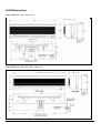
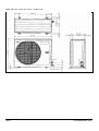
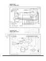
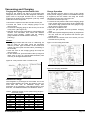
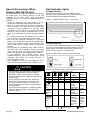
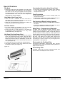
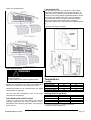
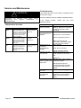
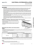
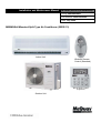
Installation and Maintenance Manual
IM-5WMF (SEER13)-0706-McQuay
Group: Wall Mounted
Part Number: R08019028218
Date: July 2006
M5WM Wall Mounted Split Type Air Conditioner (SEER 13)
Indoor Unit
Wireless Remote
Control (Standard)
Wired Wall Control
(Optional)
Outdoor Unit
Table of Contents
General Information……………………………………………….. 3
Safety Precautions………………………………………. 3
Unit Dimensions…………………………………………….……... 4
Indoor Units ……………………………………. ……....4
Outdoor Units …………………………….…….. ……....4
Installation Guidelines……………………………………………... 7
Installation Diagram……………………………………...7
Installation of Outdoor Unit……………………………... 7
Condensed Water Disposal of Outdoor Unit……. ……....7
Outdoor Unit Clearances……………………………7
Installation of the Indoor Unit……………………………7
Indoor Unit Clearances …………………………….8
Piping ……………………....................................... 8
Mounting Plate Installation ……………….. ………8
Installing Unit on Mounting Plate ………….………9
Drain Hose Installation ................................ ………9
Refrigerant Tubing…………………………………………………. 10
Tubing Length & Elevation………………………………10
Tubing Preparation……………………………………….10
Tubing Connection To Units …………..………. ………10
Electrical Connections …………………………..………... ………11
Cooling Unit ………………………...…………. ………11
Heat Pump Unit ………………………............... ………11
Wiring Diagrams ……………………………….................. ………12
Vacuuming and Charging………………………………………….. 18
Purging the Piping and the Indoor Unit…………………. 18
Additional Charge……………………………………….. 18
Charge Operation………………………………………... 18
Special Precaution When Dealing with R410A unit……. 19
Unit Indicator Lights ……………………………................ 19
IR Signal Receiver ………………...…………… 19
Cooling Only Unit ……………………............... 19
Heat Pump Unit ………………………............... 20
Special Features …………………………………..….......... 21
Dry Mode ……………………………..…........... 21
Heat Mode (Heat Pump Only) ………..………... 21
Air Flow Control ………………………..……… 21
Hot Keep (for Heat Pump Only) ………..……… 21
Overheating Protection (Heat Pump Only) ……... 21
Frost Prevention ………………………………... 21
Fan Speed and Rated Cooling Capacity ……….. 21
Main Filters ……..………………………............ 21
Cooling ……………..………………………….. 21
Electrostatic Air Purifying Filter …………......... 21
Deodorizing Filter ………………………..…….. 21
Filter Replacement ……………………………... 21
Auto Random Re-start Function ……………….. 22
Low Ambient Kit ………………………………. 22
Minimum and Maximum Operating Temperature….. 22
Remote Controller Operation Guide ……………………… 23
Service and Maintenance …………………………………. 25
Maintenance Schedule …………………………. 25
Troubleshooting ………………………………... 25
Model Numbers
Cooling Only
Indoor Unit
M5WM10F
M5WM15F
M5WM20F
M5WM25F
Outdoor Unit
M5LC10C
M5LC15C
M5LC20C
M5LC25C
Nominal Cooling – BTUH
9000
12,000
17,500
23,000
Cooling/Heat Pump
Indoor Unit
M5WM10FR
M5WM15FR
M5WM20FR
M5WM25FR
Outdoor Unit
M5LC10CR
M5LC15CR
M5LC20CR
M5LC25CR
Nominal Cooling - BTUH
9000
12,000
17,500
23,000
Page 2
Nominal Heating - BTUH
8800
12,000
18,000
23,500
IM-5WMF(SEER13)-0706
General Information
This
manual
provides
the
installation
procedures so your air conditioner unit
operates properly and provides you the service
it was designed to provide.
Special adjustment may be necessary to suit
local requirements. Before using your air
conditioner, please read this instruction manual
carefully and keep it for future reference.
!
CAUTION
Use copper conductors only. Unit terminals are not
designed to accept other types of conductors. Failure
to do so may cause damage to the equipment.
Safety Precautions
Before installing the air conditioner unit, please
read the following safety precautions carefully.
!
WARNING
• The installer must determine and follow all
applicable codes and regulations. This
equipment presents hazard of electricity, rotating
parts, sharp edges, heat and weight. Failure to
read and follow these instructions can result in
property, severe personal energy or death. This
equipment must be installed by experienced,
trained personnel only.
• Improper installation can cause equipment
damage, service personnel injury or death.
• Do not allow flammable fumes near unit or areas
sharing ventilation.
• Installation and maintenance must be performed
by qualified persons who are familiar with local
code and regulations, and experienced with this
type of appliance.
• All field wiring must be done in accordance with
industry standards and local codes.
• Inspect the unit nameplate to be certain the
voltage is the same as the voltage that will be
delivered to the unit. Improper electrical wiring
can cause property damage, severe personal
energy or death.
• The unit must be GROUNDED.
• Make sure wiring does not touch refrigerant
piping, compressor, or any moving parts of the
fan motors.
• Confirm that the power supply is switched OFF
before installing or servicing the unit.
!
WARNING
Hazardous Voltage!
Disconnect all electrical power including remote
disconnects before servicing. Failure to disconnect
power before servicing can cause severe personal
injury or death.
IM-5WMF(SEER13)-0706
!
CAUTION
• Do no install in a laundry room. Humidity and laundry
chemicals can corrode unit components.
• Do not install the unit where leakage of flammable
gas may occur. If gas leaks and accumulates around
the unit, it may cause a fire.
• Connect drainage piping properly. If drainage piping
is not connected properly, water leakage can cause
property damage.
• Do not overcharge the unit. This unit is factory precharged. Overcharge will cause over-current or
damage to the compressor.
• Keep panel closed. Unsecured panels will cause the
unit to operate noisily.
NOTICE
This product was carefully packed and thoroughly
inspected before leaving the factory. Responsibility for
its safe delivery was assumed by the carrier upon
acceptance of the shipment. Claims for loss or damage
sustained in transit must therefore be made upon the
carrier, as follow:
VISIBLE LOSS OR DAMAGE
Any external evidence of loss or damage must be
noted on the freight bill or carrier’s receipt, and signed
by the carrier’s agent. Failure to adequately describe
such external evidence of loss or damage may result in
the carrier’s refusing to honor a damaged claim. The
form required to file such a claim will be supplied by the
carrier.
CONCEALED LOSS OR DAMAGE
Concealed loss or damage means loss or damage
which does not become apparent until the product has
been unpacked. The contents may be damaged in
transit due to rough handling even though the carton
may not show external damages. When the damage is
discovered upon unpacking, make a written request for
inspection by the carrier’s agent within fifteen (15) days
of the delivery date. File a claim with the carrier since
such damage is the carrier’s responsibility.
Page 3
Unit Dimensions
Model: M5WM10F, 10FR – Indoor Unit
Model: M5WM15F, 15FR, 20F, 20FR – Indoor Unit
Page 4
IM-5WMF(SEER13)-0706
Model: M5WM25F, 25FR – Indoor Unit
Model: M5LC10C, 10CR, 15C, 15CR – Outdoor Unit
Dimension
10C/CR
15C/CR
Dimension
10C/CR
15C/CR
A
33-5/8”
33-5/8”
B
24-3/4”
28-3/4”
C
12-7/8”
12-7/8”
D
7/8”
7/8”
I
5/8”
5/8”
J
14-1/4”
14-1/4”
K
6-1/2”
6-1/2”
L
3”
3”
IM-5WMF(SEER13)-0706
E
2-5/8”
2-5/8”
F
23-3/4”
23-3/4”
G
5”
5”
H
15-3/8”
15-3/8”
M
2-7/8”
2-7/8”
Page 5
Model: M5LC20C, 20CR, 25C, 25CR – Outdoor Unit
Page 6
IM-5WMF(SEER13)-0706
Installation Guidelines
Installation Diagram
Condensate Disposal of Outdoor
Unit (Heat Pump Unit Only)
Room
Cabinet
Indoor Unit
• There are 2 holes on the base of outdoor unit
for condensed water to flow out. Insert the
drain elbow to one of the holes.
• To install the drain elbow, first insert one
portion of the hook to the base (portion A), then
pull the drain elbow in the direction shown by
the arrow while inserting the other portion to
the base. After installation, check to ensure that
the drain elbow clings to base firmly.
• If the unit is installed where the condensate
may freeze in the base, remove plug at the
bottom of unit for better drainage
• See Figure 2.
Figure 2. Condensate Disposal of Outdoor Unit
(Heat Pump Unit Only)
Remove side plate
when connecting the
piping and power
supply
Installation of Outdoor Unit
Outdoor Unit Clearances
Install the outdoor unit in a manner to prevent mixing hot
discharged air with return air flow. Also the unit should be a
suitable distance from obstructions See Figure 1 for installation
clearances. Double the dimensions shown if surroundings are
more than 72” tall, or if there is an obstruction on top. Select the
coolest possible place where intake air temperature is not greater
than the outside air temperature (maximum 113ºF).
Figure 1. Outdoor Unit Minimum Clearances
Installation of the Indoor Unit
Indoor Unit Clearance
The indoor unit must be installed in a manner
to prevent mixing the discharged air with the
return air. Please follow the installation
clearances shown in Figure 3. Do not place the
indoor unit in direct sunlight. The location must
be suitable for piping and drainage, and be
away from doors or windows.
Figure 3. Indoor Unit Minimum Clearances
IM-5WMF(SEER13)-0706
Page 7
Piping
Mounting Plate Installation
The refrigerant piping can enter the indoor unit at several
different locations. Use the knock outs provided in the room
cabinet. See Figure 4.
The mounting plate ships attached to the back of the
indoor unit. To detach for mounting on wall, remove
plastic rivet from bottom (pry loose with a knife blade)
and unhook.
Figure 4. Indoor Unit
The wall must be strong enough to support the weight
of the unit. If necessary, reinforce the wall. Drill holes in
plate to align with wall studs and attach with four (4)
screws.
If the refrigerant piping is going thru the wall behind the
indoor unit, provide a 2-1/2” hole that is slightly pitched
to the outside. See Figure 6. Hole must be located in
alignment with the arrows on the mounting plate. See
Figure 7.
Figure 6. Wall Opening for Piping
Bend the pipes carefully to prevent kinks and restrictions.
It’s best to use a tube bender. The condensation drain hose
can be taped to the pipes. See Figure 5.
Figure 5. Rear View of Indoor Unit
Figure 7. Mounting Plate/Wall Opening
Page 8
IM-5WMF(SEER13)-0706
Installing Unit on Mounting Plate
Drain Hose Installation
Hook the indoor unit onto the upper portion of the mounting
plate (engage the two hooks at the rear top of the indoor
unit with the upper edge of the plate). Properly seat the
hooks and replace the plastic rivet at the bottom.
The condensate drain hose (20” long) come factory
attached to the indoor unit. It is gravity flow. Avoid
situations that could restrict drainage. See Figure 9.
Figure 9. Drain Hose Installation
Figure 8. Installing Unit on Mounting Plate
IM-5WMF(SEER13)-0706
Page 9
Figure 11. Cutting and Flaring Tube
Refrigerant Tubing
Tubing Length & Elevation
Copper tubing to connect the indoor and outdoor units is
supplied by others or it can be ordered from the factory.
See Table 1 for requirements. Cover both tubes individually
with 3/8” wall foam insulation.
Table 1. Refrigeration Tubing Requirements
Model
Maximum length, ft., L
Max. elevation, ft., H
Max. number of bends
Liquid tube size – OD
Gas tube size - OD
10
40
16
10
¼”
3/8”
15
40
16
10
¼”
½”
20
50
26
10
¼”
½”
25
50
26
10
¼”
5/8”
Note: The refrigerant pre-charged in the outdoor unit is for tubing length up
to 25ft. See Table 5, page 18 for additional R410A refrigerant required on
longer runs.
Figure 10. Tubing Length and Elevation
Table 2: Tube Flaring Dimensions
Tube Diameter - OD
X (in.)
Inch
Imperial
Rigid
¼
.051
.028
3/8
.063
.039
½
.075
.051
5/8
.087
.067
Outdoor Unit
L
H
Tubing Connection To Units
• Connect the copper tubing to both the indoor and
outdoor units. See Figure 12.
• Torque each flare nut to specifications. See Table 3.
• Cover both tubes individually with 3/8” minimum wall
foam insulation.
Tubing Preparation
• Do not use contaminated or damaged copper tubing. Do
not remove plastic, rubber plugs and brass nuts from the
valves, fittings, tubings and coils until you are ready to
connect suction or liquid line into valves or fittings.
• If any brazing work is required, ensure that the nitrogen
gas is passed through coil and joints while the brazing
work is done. This will eliminate soot formation on the
inside wall of the copper tubing.
• Cut the copper tubing with a tube cutter. See Figure 11.
• Remove burrs from cut ends by holding tubing
downwards to prevent metal chips from entering the
tubing.
• Slide the flare nuts, for both the indoor unit and outdoor
unit onto the copper tubing.
• Flare the tubing as shown in Figure 11, Figure 12 and
Table 2.
• The flare must be even and not cracked or scratched.
Page 10
Table: Flare Nut Torque Specifications
Tube Size (in.)
Torque (ft./lb.)
¼
13.3
3/8
31.0
½
40.6
5/8
48.0
Figure 12. Flare Tubing Connections
IM-5WMF(SEER13)-0706
Electrical Connections
Figure 14. Terminal Block and wire Clamp
WARNING
!
Improper installation can cause severe personal
injury or death. Wiring must be done by a qualified
electrician in compliance with local codes. Model
10F, 10FR, 15F and 15FR are using two separate
power
supply.
Indoor
unit
powered
by
115V/1Ph/60Hz. Outdoor unit powered by 208230V/1Ph/60Hz.
• Wiring must be in accordance with all applicable
electrical codes.
• Wires must not touch the refrigerant piping,
compressor or any moving part.
• All electrical field wiring must be clamped at both the
indoor unit and the outdoor unit. See Figure 14 for
typical clamp.
• See Table 4, figure 13 and Figure 15 for the number
of wires, wire gauge and fuse/circuit breaker size
required.
Table 4: Wire and Fuse/Breaker Requirements
10/15
Unit Size
20/25
Indoor Outdoor
Voltage-1Ph/60Hz
115V
208/230V 208/230V
Power supply wire size
14 ga.
14 ga.
Number of wires
2 + gnd.
2 + gnd.
Connecting wire size
14 ga.
Number of wires – A/C
2
Number of wires - HP
4
Fuse/Breaker size
15 amp
15 amp
* Not including the Outdoor Coil Sensor Cable.
12ga.
2 + gnd.
14 ga.
3 + gnd.
5 + gnd.
20 amp
Figure 13. Cooling Only Size 10 & 15
Indoor Unit
Terminal Block
Connecting Wires
COMP
Figure 15. Heat Pump Unit Size 10 & 15
Outdoor coil sensor, 2 conductor cable, (26 feet long)
shipped with the indoor unit. Extend with 22 ga. low voltage
wire if not long enough to reach outdoor unit.
Indoor Unit
Terminal Block
Connecting Wires
4WV
4WV
OF
OF
Comp
Comp
N2
N2
N1
N1
Outdoor Unit
Terminal Block
Power L2
supply
208/230V L1
L
COMP
N2
Outdoor Unit
Terminal Block
L
N Power
L1 supply
115V
N2
N1
N1
Power L2
supply
208/230V L1
L
L
N Power
L1 supply
115V
!
NEC requires an approved
electrical disconnect within sight
of the unit so that anyone
working on the unit can turn the
power off and see that its not
accidentally turned back on. This
will require two disconnects, one
by the outdoor unit and one by
the indoor unit.
IM-5WMF(SEER13)-0706
!
NEC requires an approved
electrical disconnect within
sight of the unit so that
anyone working on the unit
can turn the power off and
see that its not accidentally
turned back on. This will
require two disconnects, one
by the outdoor unit and one
by the indoor unit
Page 11
Figure 16. Cooling Only Size 20 & 25
Indoor Unit
Terminal Block
Connecting Wires
Figure 17. Heat Pump Unit Size 20 & 25
Outdoor Unit
Terminal Block
COMP
COMP
L1
N2
L2
Outdoor coil sensor, 2 conductor cable, (26 feet long)
shipped with the indoor unit. Extend with 22 ga. low voltage
wire if not long enough to reach outdoor unit.
Connecting Wires
Indoor Unit
Terminal Block
N1
Outdoor Unit
Terminal Block
L
Power L1
supply
208/230V L2
4WV
A
L1
OF
4WV
L2
Comp
OF
N2
COMP
L1
N1
L2
L
!
NEC requires an approved
electrical disconnect within sight
of the unit so that anyone
working on the unit can turn the
power off and see that its not
accidentally turned back on. This
will require two disconnects, one
by the outdoor unit and one by
the indoor unit.
L1
L2
Power L1
supply L2
208/230V
!
Page 12
NEC requires an approved
electrical disconnect within
sight of the unit so that
anyone working on the unit
can turn the power off and
see that its not accidentally
turned back on. This will
require two disconnects, one
by the outdoor unit and one
by the indoor unit
IM-5WMF(SEER13)-0706
Wiring Diagrams
INDOOR UNIT
MODEL: M5WM 10F – 15F
115V
OUTDOOR UNIT
MODEL: M5LC 10C – 15C
208/230V
IM-5WMF(SEER13)-0607
Page 13
INDOOR UNIT
MODEL :M5WM 20F
OUTDOOR
OUTDOOR
UNIT UNIT
MODEL:
M5LC
20C
MODEL: M5LC 20C
– 25C
Page 14
IM-5WMF(SEER13)-0706
INDOOR UNIT
MODEL: M5WM 25F
OUTDOOR UNIT:
MODEL: M5LC 25C
IM-5WMF(SEER13)-0706
Page 15
INDOOR UNIT
MODEL: M5WM 10FR – 15FR
OUTDOOR UNIT
MODEL:
M5LC 10CR – 15CR
Page 16
IM-5WMF(SEER13)-0706
INDOOR UNIT
MODEL: M5WM 20FR
OUTDOOR UNIT
MODEL: M5LC 20CR
IM-5WMF(SEER13)-0706
Page 17
INDOOR UNIT
MODEL: M5WM 25FR
OUTDOOR UNIT:
MODEL: M5LC 25CR
Page 18
IM-5WMF(SEER13)-0706
Vacuuming and Charging
Purging the Piping and the Indoor Unit
Charge Operation
Except for the outdoor unit which is pre-charged with
refrigerant, the indoor unit and the refrigerant connection
pipes must be air-purged because the air containing
moisture that remains in the refrigerant cycle may cause
malfunction of the compressor.
This operation must be done by using a gas cylinder
and a precise weighing machine. The additional charge
is topped-up into the outdoor unit using the suction
valve via the service port. See Figure 20.
• Remove the service port cap.
• Connect the low pressure side of the charging gauge
to the suction service port center of the cylinder tank
and close the high pressure side of the gauge. Purge
the air from the service hose.
• Start the air conditioner unit.
• Open the gas cylinder and low pressure charging
valve.
• When the required refrigerant quantity is pumped into
the unit, close the low pressure side and the gas
cylinder valve.
• Disconnect the service hose form service port. Put
back the service port cap.
• Remove the caps from the valve and the service port.
• Connect the center of the charging gauge to the
vacuum pump.
• Connect the charging gauge to the service port of the
3-way valve. (See Figure 18.)
• Start the vacuum pump. Evacuate for approximately 30
minutes. The evacuation time varies with different
vacuum pump capacity. Confirm that the charging
gauge needle has moved towards -760mmHg
(-29.9”Hg).
Caution:
• If the gauge needle does not move to -760mmHg, be
sure to check for gas leaks (using the refrigerant
detector) at flare type connection of the indoor and
outdoor unit and repair the leak before proceeding to
the next step.
• Close the valve of the charging gauge and stop the
vacuum pump.
• On the outdoor unit, open the suction valve (3 way) and
liquid valve (2 way) (in anti-clockwise direction) with
4mm key for hexagon sacked screw.
Figure 19. Vacuuming Schematic
Figure18. 3-way Suction Valve on Outdoor Unit
Figure 20. Charging Schematic
Additional Charge
The refrigerant is pre-charged in the outdoor unit. If the
tubing length between the indoor and outdoor unit is no
more than 25ft. than an additional charge after
evacuation is not necessary. If the tubing length is more
than 25ft., use additional R410A as indicated in Table 5.
Table 5. Additional R410A ounces (when tubing length is
more than 25 feet
Model
26’ -33’
34’ – 40’
41’ – 50’
10F
1.2
2.0
15F
1.2
2.0
20F
1.2
2.0
3.5
25F
2.8
5.3
9.4
10FR
1.6
2.8
15FR
1.6
2.8
20FR
2.0
3.5
5.8
25FR
4.0
7.0
11.8
IM-5WMF(SEER13)-0706
Page 19
Special Precautions When
Dealing With R410A Unit
R410A is a new HFC refrigerant which does not damage
the ozone layer. The working pressure of this new
refrigerant is 1.6 times higher than conventional
refrigerant (R22), thus proper installation/servicing is
essential.
• Never use refrigerant other than R410A in an airconditioner which designed to operate with R410A.
• POE oil is used as lubricant for R410A compressor,
which is different from the mineral oil used for R22
compressor. During installation or servicing, extra
precaution must be taken not to expose the R410A
system too long to moist air. Residual POE oil in the
piping and components can absorb moisture from the
air.
• To prevent mischarging, the diameter of the service
port on the flare valve is different from that of R22.
• Use tools and materials exclusively for refrigerant
R410A. Tools exclusively for R410A are manifold valve,
charging hose, pressure gauge, gas leak detector, flare
tools, torque wrench, vacuum pump and refrigerant
cylinder.
• As an R410A air conditioner incurs higher pressure
than R22 units, it is essential to choose the copper
pipes correctly. Never use copper pipes thinner than
0.8mm even though they are available in the market.
• If the refrigerant gas leakage occurs during
installation/servicing, be sure to ventilate fully. If the
refrigerant gas comes into contact with fire, a
poisonous gas may occur.
• When installing or removing an air conditioner, do not
allow air or moisture to remain in the refrigerant cycle.
!
Unit Indicator Lights
IR Signal Receiver
When an infrared remote control operating signal is
transmitted, the signal receiver on the indoor unit beeps to
confirm acceptance of the signal transmission.
Figure 21. Indicator Lights Location – Indoor Unit
Cooling Only Unit
Table 6 shows the LED indicator lights for the cooling only
unit under normal operation and fault conditions. The LED
indicator lights are located at the bottom right side of the
indoor unit. (See Figure 21 and Figure 22).
Figure 22. LED Indicator Lights for Cooling Only Unit
CAUTION
• R410A must be charged as liquid. Usually R410A
cylinder is equipped with a dip-pipe for liquid
withdrawal. If there is no dip-pipe, the cylinder
should be inverted so as to withdraw liquid R410A
from the valve.
• Do not top-up when servicing leak, as this will
reduce the unit performance. Vacuum the unit
thoroughly and then charge the unit with fresh
R410A according to the amount recommended in
the specification.
• Do not touch the compressor or refrigerant piping
when the chiller is running. If necessary wear
protective gloves.
Table 6. LED Indicator Lights: Normal Operation and Fault
Conditions for Cooling Only Unit
Mode
Action
or
Dry
Power Sleep Timer
Fault
Timer
Sleep
Dry
Room air
Repair
Once
sensor
or
every 2
contact
replace
sec.
loose/short
Indoor coil
Repair
Twice
sensor
or
every 2
contact
replace
sec.
loose/short
Sensor coil Check
circuit
problem,
3 times
compressor breaker,
every 2
check
overload
sec.
for gas
protection
leak
trip or gas
leak.
ON
Page 20
/
ON or OFF
Blinking
IM-5WMF(SEER13)-0706
Heat Pump Unit
Table 7 shows the LED indicator lights for the heat pump unit under normal operation and fault conditions. The LED
indicator lights are located at the bottom right side of
the indoor unit.
The heat pump units are equipped to maintain selected room temperature by switching automatically to either “cool” or
“heat” mode.
Figure 23. LED Indicator Lights: Normal Operation and
Fault Conditions for Heat Pump Unit
Table 7. LED Indicator Lights: Normal Operation and Fault Conditions for Heat Pump Unit
Mode or Fault
Cool
Dry
Fan
Heat
Sleep
/
/
/
/
ON
Action
/
Cooling
Dry
Fan
Heat
Auto mode in heating
operation. *
-
Auto mode in cooling
operation. *
-
Compressor cycling on
overload
Low outdoor air flow, defective
compressor or overload.
Indoor coil sensor loose
or defective
Attach or replace.
Outdoor coil sensor
loose or defective
Attach or replace.
Room air sensor loose
or defective
Attach or replace.
Unit Malfunctions
If in AUTO or SLEEP mode, switch to
Heat, turn SLEEP off, unplug power
cord and plug back in.
If both lights blink with unit in Heat or
Cool and SLEEP off, the problem may
be coil sensor, compressor has tripped
or low refrigerant.
ON or OFF
Blinking
* Unit has 10 minutes delay before it will switch between modes.
IM-5WMF(SEER13)-0706
Page 21
Special Features
Dry Mode
Overheating Protection (Heat Pump Only)
• Select this mode when the standard Cool mode does
not provide sufficient dehumidification. The compressor
and indoor low fan will cycle together and will operate
for longer periods of time to provide the increased rate
of dehumidification. As a result, the room temperature
differential may increase slightly.
• If the indoor coil temperature exceeds 145ºF because
of high ambient conditions, dirty air filter, etc., the
compressor will turn off.
Heat Mode (Heat Pump Only)
• When the unit is switched on from cold start or
defrosting cycle, the indoor fan will start to operate only
after the indoor coil becomes warmer.
• When the set temperature is achieved, the indoor fan
will stop as the indoor coil starts to cool.
Air Flow Control
• For more effective air circulation, you can manually
adjust the air discharge grille to the left or right.
• During cool and dry mode operation, do not direct the
air discharge louver downwards as it may cause
condensate to drip. (See figure 24).
Hot Keep (For Heat Pump Only)
• With the Hot Keep switch OFF, the indoor fan will stop
when coil temperature drops to 86ºF. With the switch
ON, the fan will not stop unless coil temperature drops
below 65ºF. With the switch in INTERNAL, and the unit
is not heating, the fan is on for 30 seconds and off for 2
min. (See Figure 24).
• In cool mode, fan runs continuous at selected speed.
• The switch is located on front of the indoor unit, above
the ON/OFF switch (See Figure 24).
Frost Prevention
• If the indoor coil starts to frost in cooling mode, the
compressor will stop.
• If the outdoor coil becomes frosted, heating will stop for
a few minutes while the unit goes into defrost.
Fan Speed and Rated Cooling Capacity
• The rated cooling capacity is provided at the maximum
fan speed.
• The cooling capacity is slightly lower when the unit is
operating at MEDIUM and LOW fan speed.
Main Filters – Permanent and Washable
Air filters must be cleaned at regular intervals. Twice
annually may be adequate in some areas, while twice
monthly may be required in others. Areas with high dirt
and lint content or heavy usage of units require more
frequent filter maintenance than those areas of relatively
clean operating or low usage conditions. Unit malfunction
will occur if air filters are not kept clean. Vacuum the
filters from the dirty side or wash with hot water and a
mild detergent. Allow the filters to dry thoroughly before
replacing them. See Figure 25.
Electrostatic Air Purifying Filter
Pre-charged electrostatic polypropylene filter removes
microscopic dust, smoke and small invisible particles to
keep the room air clean.
Figure 24
Deodorizing Filter
Activated carbon filter removes unwanted smells and
odors in the air and keeps the room air fresh.
Page 22
IM-5WMF(SEER13)-0706
Figure 25. Installing Filters
Low Ambient Kit
With this option, the unit can cool down to 32ºF outdoor
temperature. (Standard units only cool down to 66ºF). To
install, wire the Fan Speed Control Module (FSCM) in the
outdoor unit per wiring diagram supplied with the kit. Attach
the Outdoor Coil Sensor to the return bend as shown in
Figure 26. Wrap sensor and return bend with insulating
tape to promote accurate sensing of the refrigerant
temperature. Refer also to the instructions supplied with the
kit.
Figure 26 Low Ambient Location
Filter Replacement
WARNING
!
Disconnect the main power supply before opening
the return air grille.
DO NOT restore power until the grille is closed.
Minimum and Maximum Operating
Temperature
Cooling
Replace the electrostatic air purifying and deodorizing
filters every 6 months or sooner if they turn brown.
Replacement filters can be purchased from your sales
representative or distributor.
Use the new filter immediately once it has been
removed from the package.
Auto Random Re-start Function
If there is a power loss to the building, the units will
randomly restart when the power is restored. Control
will restart at the last setting regardless of how long the
power was off.
IM-5WMF(SEER13)-0706
Temperature
Minimum Indoor
Maximum Indoor
Minimum Outdoor
Maximum Outdoor
Ts ºF
67
80
*66
115
Th ºF
57
67
57
75
Heating (Heat Pump Only)
Temperature
Minimum Indoor
Maximum Indoor
Minimum Outdoor
Maximum Outdoor
Ts ºF
50
80
16
75
Th ºF
16
65
Ts = Dry Bulb Temperature, Th = Wet Bulb Temperature
* 32ºF with optional Low Ambient Kit
Page 23
Remote Controller Operation Guide
1) Transmission Source
• The source where the signal is transmitted.
2) Signal Transmission Indication
• Blinks to confirm the last setting has been transmitted to
the unit.
3) “ON/OFF” Button
• Press once to start the unit.
• Press again to stop the unit.
4) Temperature Setting
• To set the desired room temperature, press the + or –
button to increase or decrease the set temperature.
• The temperature setting range is from 60ºF to 86ºF
(Optional setting 68ºF to 86ºF).
• Press both buttons simultaneously to toggle + and – from
ºC to ºF setting.
5) Operation Mode
• Press the MODE button to select the type of operating
mode.
• For cooling only unit, the available modes are: COOL,
DRY and FAN.
• For heat pump unit, the available modes are: AUTO,
COOL, DRY, FAN and HEAT.
6) Fan Speed Selection
• Press the
button continuously to toggle the fan speed
in the following order:
Low
Med
High
Auto
• Stop pressing when the desired fan speed appears on
the display screen.
7) Turbo Function
for fast cooling or heating operation.
• Press
• The temperature will be increased internally if it is in HEAT mode, decreased if in COOL and DRY mode.
• Fan speed will be increased if it is not at maximum speed.
is pressed again or after 20 minutes.
• The temperature and fan speed will resume to user setting if
• Available under HEAT, COOL and DRY modes only.
8) ON Timer Setting
• Press the SET button will activate the on timer function.
• Set the desired on time by pressing the SET button continuously. If the timer is set to 7.30am, the air
conditioner will turn on at 7.30am sharp.
• Press the CLR button to cancel the on timer setting.
9) OFF Timer Setting
• Press the SET button will activate the off timer function.
• Set the desired of time by pressing the SET button continuously.
• Press the CLR button to cancel the off timer setting.
10) Automatic Air Swing (optional)
• Press the SWING button to activate the automatic air swing function.
• To distribute the air to a specific direction, press the SWING button and wait until the louver move to the
desired direction and press the button once again.
Page 24
IM-5WMF(SEER13)-0706
11) Sleep Mode Setting
• Press the SLEEP button will activate the sleep mode function.
• This is an energy saving option. When the unit is operating under cooling mode, the set temperature is increased
by 0.5ºC after the first half an hour, another 0.5ºC after the second half an hour and 1ºC after the following 1 hour.
This function will prevent excessive cooling during summer season.
• When the unit is operating under heating mode, the set temperature is decreased by 1ºC after the first half an
hour, another 1ºC after the second half an hour and 1ºC after the following 1 hour. This function will prevent night
sweat during summer season.
• This function is available under COOL, HEAT and AUTO mode.
Figure 27 Sleep Mode Setting
12) Clock Time Setting
• Press + button to increase the clock time.
• Press – button to decrease the clock time.
13) Personalize Setting
• Press and hold for 3 seconds, then
will blink. Press again to cycle between
P1
•
•
•
and
P1
.
P2
Set the desired setting, then leave the handset for 4 seconds without pressing any key and it will save the setting
into the program.
Press once to activate the P1 setting, press again to cycle between P1 and P2.
Press any key to deactivate the personalize setting.
14) Ionizer Setting (optional)
• Press will activate the ionizer function.
• Press again to deactivate the function.
Symbol Identification
IM-5WMF(SEER13)-0706
Page 25
Service and Maintenance
Troubleshooting
!
CAUTION
If any malfunction of the unit is noted, immediately switch
off the power supply.
Disconnect the electrical power supply before
performing
any
service,
maintenance
or
troubleshooting.
Maintenance Schedule
Item
Indoor Air
Filters
Indoor
Cabinet
Outdoor
Unit
Maintenance Procedures
Lift the return air grille and
remove the filters (See
Figure 23). Clean the filters
by using a vacuum cleaner
or wash in lukewarm water
and soap. Rinse and dry
before reinstalling.
Remove any dust on the
grille or panel by wiping it
with a soft cloth soaked in
lukewarm water (below
40ºC / 104ºF) and a mild
detergent.
Clean the louvers and coil.
Be careful not to bend or
flatten the aluminium fins.
DO NOT use cleaning
fluids that might corrode
the coil.
Frequency
As required to
prevent restriction
of air flow.
Check the following chart for possible causes/treatments.
If the trouble persists,
dealer/serviceman.
Trouble
The compressor
does not operate.
Fans and
compressor do not
operate.
As required to
maintain
appearance.
As required to
prevent restriction
of air flow.
call
your
local
Possible Cause/Treatment
Protection against frequent
starting. Wait for 3 to 4 minutes
for the compressor to start
operating.
Power failure.
Check fuse or circuit breaker.
Power supply disconnect off.
Air flow too low or
insufficient
cooling/heating
capacity.
Discharge air flow
has bad odor.
Condensation on the
return air grille of the
indoor unit.
Condensate leaking
into room.
Hissing sound from
the unit during
operation.
Page 26
please
Delay timer may be set
incorrectly. Adjust timer setting
by using remote controller.
Dirty air filters.
Open doors or window.
Adjust thermostat setting.
Smoke, perfume, etc. may
have collected on the indoor
coil.
Clean coil.
Use dry mode. High humidity in
conditioned space.
Set temperature too low.
Increase temperature setting
and operate unit at high fan
speed.
Condensate drain plugged.
Refrigerant fluid flowing into the
evaporator coil. Operate for a
while to see if sound goes
away.
IM-5WMF(SEER13)-0706
This document contains the most current product information as of this printing. The manufacturer reserves the right to
revise any of the specification and design contain herein at any time without prior notification.