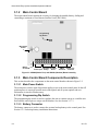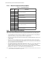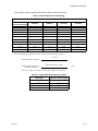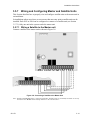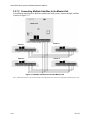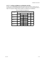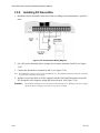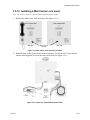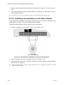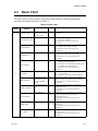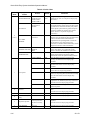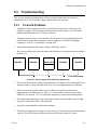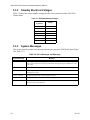
1
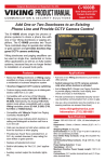
SILENT KNIGHT
5000 Series
Installation and
Operation Manual
Entry System
Part Number 151174D, 01/03
Content
Section 1
Overview
1.1
1.2
1.3
...................................................................................................................................................... 1-1
User Features ............................................................................................................................................ 1-1
What’s In the Box .................................................................................................................................... 1-2
About this Manual .................................................................................................................................... 1-2
1.3.1 Terminology ...................................................................................................................................... 1-2
Section 2
Telephone Requirements
2.1
2.2
Before Connecting The Control Panel ..................................................................................................... 2-1
INDUSTRY CANADA WARNINGS ..................................................................................................... 2-2
2.2.1 AVIS D’INDUSTRIE CANADA ..................................................................................................... 2-3
Section 3
Installation Instructions
3.1
3.2
3.3
3.4
3.5
151174
...................................................................................................... 2-1
........................................................................................................... 3-1
Model 5083/84 Parts ................................................................................................................................ 3-1
3.1.1 Keypad and LCD .............................................................................................................................. 3-1
3.1.2 Main Control Board .......................................................................................................................... 3-2
3.1.3 Main Control Board Components Description ................................................................................. 3-2
3.1.3.1 Main Power Switch ................................................................................................................ 3-2
3.1.3.2 Programming Dip Switch ....................................................................................................... 3-2
3.1.3.3 Battery Connector .................................................................................................................. 3-2
3.1.3.4 AC Power Input Terminals .................................................................................................... 3-3
3.1.3.5 Door and Auxiliary Relay Terminals ..................................................................................... 3-3
3.1.3.6 The Door and Auxiliary Reset Terminals .............................................................................. 3-3
3.1.3.7 SBUS Terminals .................................................................................................................... 3-3
3.1.3.8 Phone line Terminals ............................................................................................................. 3-3
3.1.4 Board Components Description ........................................................................................................ 3-4
Mounting Instructions .............................................................................................................................. 3-4
Flush Mount ............................................................................................................................................. 3-5
Surface Mount .......................................................................................................................................... 3-6
Wiring Instructions .................................................................................................................................. 3-7
3.5.1 Power Requirements ......................................................................................................................... 3-7
3.5.2 Installing the AC Transformer .......................................................................................................... 3-7
3.5.3 Transient Protection For 5083/5084 Panels ...................................................................................... 3-8
3.5.4 How to Verify Earth Ground ............................................................................................................ 3-8
3.5.5 Battery Connections .......................................................................................................................... 3-9
3.5.6 SBUS Wiring .................................................................................................................................. 3-10
3.5.6.1 Calculating Wiring distance for SBUS modules .................................................................. 3-10
3.5.7 Wiring and Configuring Master and Satellite Units ....................................................................... 3-13
3.5.7.1 Wiring a Satellite to the Master unit .................................................................................... 3-13
3.5.7.2 Connecting Multiple Satellites to the Master Unit ............................................................... 3-14
i
Series 5000 Entry System Installation/Operation Manual
3.5.7.3 Configuring Master and Satellite Unit IDs .......................................................................... 3-15
3.5.8 Installing DC Doorstrike ................................................................................................................. 3-16
3.5.9 Installing an AC Doorstrike ............................................................................................................ 3-17
3.5.10 Doorstrike Reset Switch ................................................................................................................. 3-17
3.5.11 Installing Phone Lines .................................................................................................................... 3-18
3.5.11.1 Using Ground Start ............................................................................................................. 3-18
3.5.12 Installing a Mail Carrier Lock panel. .............................................................................................. 3-19
3.5.13 Installing a Sonalert/Piezo to the Alarm Output ............................................................................. 3-20
3.6 Model 5076 Heater Kit .......................................................................................................................... 3-21
3.6.1 To Install the 5076 Heater .............................................................................................................. 3-21
Section 4
Operation Modes
............................................................................................................................... 4-1
4.1
Entering, Changing Options and Exiting Operating Modes .................................................................... 4-2
4.1.1 To enter an operating mode: ............................................................................................................. 4-2
4.1.1.1 If The Access Code Is Not Known: ....................................................................................... 4-2
4.1.2 To Change a Selection. ..................................................................................................................... 4-2
4.1.3 To Skip a Selection. .......................................................................................................................... 4-2
4.1.4 To Exit Any Operating Mode. .......................................................................................................... 4-2
4.2 Operating Modes ...................................................................................................................................... 4-3
4.2.1 Operation Mode 0:
System Options 4-3
4.2.2 Operation Mode 1
User Information 4-6
4.2.2.1 Add User Information ............................................................................................................ 4-6
4.2.2.2 Edit User Information ............................................................................................................ 4-7
4.2.2.3 Delete User Information ......................................................................................................... 4-8
4.2.3 Operating Mode 2
Time Set 4-8
4.2.4 Operating Mode 3
Activate Door Relay 4-9
4.2.5 Operating Mode 4
Activate Auxiliary Relay 4-9
4.2.6 Operating Mode 5
Telephone 4-10
4.2.7 Operating Mode 6
Memory Clear 4-10
4.3 Quick Chart ............................................................................................................................................ 4-11
Section 5
Testing and Troubleshooting
........................................................................................... 5-1
5.1
5083/5084 Field Test ............................................................................................................................... 5-1
5.1.1 Test the Doorstrike Operation ........................................................................................................... 5-1
5.1.2 Test the Dialing Operation ................................................................................................................ 5-1
5.2 Satellite Field Test ................................................................................................................................... 5-2
5.2.1 Test the Doorstrike Operation ........................................................................................................... 5-2
5.2.2 Test the Dialing Operation ................................................................................................................ 5-2
5.3 Troubleshooting ....................................................................................................................................... 5-3
5.3.1 To Avoid Problems ........................................................................................................................... 5-3
5.3.2 Standby Electrical Voltages .............................................................................................................. 5-4
5.3.3 System Messages .............................................................................................................................. 5-4
ii
151174
Content
Section 6
User Operation
6.1
6.2
6.3
6.4
6.5
..................................................................................................................................... 6-1
Visitor Operation ...................................................................................................................................... 6-1
Tenant Access Operation ......................................................................................................................... 6-1
Auxiliary Door Access Operation ............................................................................................................ 6-2
Postal Access Operation ........................................................................................................................... 6-2
Door Attendant Notification Operation ................................................................................................... 6-2
Section 7
Programming information record
............................................................................... 7-1
7.1
7.2
System Options Record ............................................................................................................................ 7-1
User Information Record ......................................................................................................................... 7-2
151174
iii
Series 5000 Entry System Installation/Operation Manual
iv
151174
Section 1
Overview
The Silent Knight Models 5083 Handsfree and 5084 Handset make up a family of entry
security systems which provide reliable entry control for large multi-tenant buildings.
1.1
User Features
•
Only resident-side telephones will open doors
•
Door-strike time lengths are programmable to fit the installation requirements
•
Programmable user codes for keyless entry (4 to 6 digits)
•
All tenant phone numbers remain confidential
•
Optional automatic enable/disable times for auxiliary relay
•
Optional touch-tone auxiliary relay activation from user phone
•
Rotary or DTMF dialing
•
20-digit phone numbers
•
Audio On or Off option when dialing
•
1,000 user capacity
•
Ground start telephone systems
•
Call length 1-255 seconds
•
User number length 1-8 digits
•
Dial through PBX systems
•
Door open time 1-255 seconds
•
Selectable system messages
•
Modular design for multiple door access points
151174
1-1
Series 5000 Entry System Installation/Operation Manual
1.2
What’s In the Box
Table 1-1 describes what you will find when you open the box of the 5083/5084 Entry System
Control Panel.
Table 1-1: What’s in the Box
Item
1.3
P/N
5083
5084
Where to Find
Stainless steel cabinet with
control inside
5083/5084
Section 3.4
Wall Mount Bracket
130083
Section 3.3
Keys (in small envelope)
1347
Battery
6912
Section 3.5.5
Transformer
9220
Section 3.5.2
Transient Protector
7890
Section 3.5.3
1N5401 Diode
N/A
Section 3.5.8
Series 5000 Installation Manual
150174
About this Manual
This manual explains the installation and operation procedures for the 5000 Series System.
Section 2 describes telephone company requirements and other specifications that must be
met before installing the system. Section 3 provides installation instructions. The
Programming sequence and operating procedures are described in Section 4. Section 5
describe field test procedures and troubleshooting concerns. Section 6 describes user and
visitor operation of the system.
1.3.1
Terminology
In this manual the term “User” refers to any one that will be using the system such as a tenant
or resident of the facility using the 5000 series entry system.
1-2
151174
Section 2
Telephone Requirements
This section contains information about the telephone companies’ installation requirements
and should be reviewed prior to system installation.
2.1
Before Connecting The Control Panel
The following information must be provided before connecting this system to the phone lines
if it is requested by the telephone company.
Manufacturer
Silent Knight
Model Number
5083 & 5084
FCC Registration
AC6USA-27622-MT-T
Ringer Equivalence
0.4B AC and 0.3 DC
Type of jack
RJ11X
This device may not be directly connected to coin telephone or party line service.
Under certain circumstances the telephone company may temporarily discontinue service and/
or make changes in its facilities and services that may affect the operation of this device.
However, the telephone company is required to give adequate notice in writing of such
changes or interruptions.
**Important Notice**
Due to wide variations in telephone company exchange switching equipment, Silent Knight can no longer guarantee that the
5000 Series Apartment Entry System will function properly when used to decode the digit “6” from rotary (dial type)
telephones. For those exchanges where rotary phones will not work, each apartment must have a Touch-Tone® telephone.
151174
2-1
Series 5000 Entry System Installation/Operation Manual
2.2
INDUSTRY CANADA WARNINGS
NOTICE:
The Industry Canada Label identifies certified equipment. This certification means that the
equipment meets telecommunications network protective, operational and safety requirements
as prescribed in the appropriate Terminal Equipment Technical Requirements document(s).
The Department does not guarantee the equipment will operate to the user’s satisfaction.
Before installing this equipment, users should ensure that it is permissible to be connected to
the facilities of the local telecommunications company. The equipment must also be installed
using an acceptable method of connection. The customer should be aware that compliance
with the above conditions may not prevent degradation of service in some situations.
Repairs to certified equipment should be coordinated by a representative designated by the
supplier. Any repairs or alterations made by the user to this equipment, or equipment
malfunctions, may give the telecommunications company cause to request the user to
disconnect the equipment.
Users should ensure for their own protection that the electrical ground connections of the
power utility, telephone lines and internal metallic water pipe system, if present, are
connected together. This precaution may be particularly important in rural areas.
Caution: Users should not attempt to make such connections themselves, but should contact
the appropriate electric inspection authority, or electrician, as appropriate.
NOTICE: The Ringer Equivalence Number (REN) assigned to each terminal device provides
an indication of the maximum number of terminals allowed to be connected to a telephone
interface. The termination on an interface may consist of any combination of devices subject
only to the requirement that the sum of the Ringer Equivalence Number of all the devices does
not exceed 5.
2-2
151174
Telephone Requirements
2.2.1
AVIS D’INDUSTRIE CANADA
AVIS:
L’étiquette d’Industrie Canada identifie le matériel homologué. Cette étiquette certifie que le
matériel est conforme aux normes de protection, d’exploitation et de sécurité des réseaux de
télécommunications, comme le prescrivent les documents concernant les exigences
techniques relatives au matériel terminal. Le Ministère n’assure toutefois pas que le matériel
fonctionnera à la satisfaction de l’utilisateur.
Avant d’installer ce matériel, l’utilisateur doit s’assurer qu’il est permis de le raccorder aux
installations de l’entreprise locale de télécommunication. Le matériel doit également être
installé en suivant une méthode acceptée de raccordement. L’abonné ne doit pas oublier qu’il
est possible que la comformité aux conditions énoncées ci-dessus n’empêche pas la
dégradation du service dans certaines situations.
Les réparations de matériel homologué doivent être coordonnées par un représentant désigné
par le fournisseur. L’entreprise de télécommunicationspeut demander à l’utilisateur de
débrancher un appareil à la suite de réparations ou de modifications effectuées par l’utilisateur
ou à cause de mauvais fonctionnement.
Pour sa propre protection, l’utilisateur doit s’assurer que tous les fils de mise à la terre de la
source d’énergie électrique, des lignes téléphoniques et des canalisations d’eau métalliques,
s’il y en a, sont raccordés ensemble. Cette précaution est particulièrement importante dans les
régions rurales. Avertissement: L’utilisateur ne doit pas tenter de faire ces raccordements luimême; il doit avoir recours à un service d’inspection des installations électriques, ou à un
électricien, selon le cas.
AVIS:
L’indice d’équivalence de la sonnerie (IES) assigné à chaque dispositif terminal indique le
nombre maximal de terminaux qui peuvent être raccordés à une interface. La terminaison
d’une interface téléphonique peut consister en une combinaison de quelques dispositifs, à la
seule condition quela somme d’indices d’équivalence de la sonnerie de tous les dispositifs
n’excède pas 5.
151174
2-3
Series 5000 Entry System Installation/Operation Manual
2-4
151174
Section 3
Installation Instructions
This section describes the different parts of the 5000 Series Entry System circuit board.
3.1
Model 5083/84 Parts
Figure 3-1 and Figure 3-2 show the printed circuit boards of the 5083 and 5084 main module.
These printed circuit boards contain the switches, LCD, keypad and terminals required to run
the main control system.
3.1.1
Keypad and LCD
The LCD is used for prompting the user and reflecting the numbers pressed on the keypad.
When the user sees that the correct data is displayed, pushing the
into memory.
key will enter the data
Figure 3-1 050830 Keypad Board Assembly
151174
3-1
Series 5000 Entry System Installation/Operation Manual
3.1.2
Main Control Board
The main control board contains the circuitry for charging the standby battery, dialing and
controlling a maximum of four Remote Satellite Units (5083/5084).
Programming
Dip Switch
Main Power
Switch
Battery
Connector
AC
Door/Aux Door/Aux
Power Input Relays
Reset
SBUS
Phone Line
Terminals Terminals
Figure 3-2 050800(Hands Free) and 050849 (Handset) Board Assembly
3.1.3
Main Control Board Components Description
This section describes the components on the main control board as shown in Figure 3-2.
3.1.3.1 Main Power Switch
The main power switch, in the On position applies power to the main control panel. In the Off
position power is removed from the main control panel and all system options and user
information is stored in Flash memory.
3.1.3.2 Programming Dip Switch
The programming dip switch is used to configure the unit as a master unit or as a satellite unit.
Each satellite unit requires a unique unit ID number. See also Section 3.5.7.3.
3.1.3.3 Battery Connector
The battery connector is used to connect the systems backup battery to the control panel. See
Section 3.5.5 for backup battery installation instructions.
3-2
151174
Installation Instructions
3.1.3.4 AC Power Input Terminals
The AC power input terminal are used to connect the AC transformer to the control panel. See
Section 3.5.2 for AC transformer wiring instructions.
3.1.3.5 Door and Auxiliary Relay Terminals
The door and auxiliary relay terminal can be used to connect a AC or DC door strike which is
control by the control panel. The maximum allowable draw from a doorstrike is 250 VAC @
1A.
3.1.3.6 The Door and Auxiliary Reset Terminals
The Door and Auxiliary Reset Terminals are used to connect a door reset switch to the control
panel. See Section 3.5.10 for more information.
3.1.3.7 SBUS Terminals
The SBUS terminals are used to connect satellite units to the master control unit in a system.
See Section 3.5.7 for more information.
3.1.3.8 Phone line Terminals
The phone line terminals are used to connect the system phone line to the control panel. See
Section 3.5.11 for more information.
151174
3-3
Series 5000 Entry System Installation/Operation Manual
3.1.4
Board Components Description
Table 3-1: Terminal Descriptions
Terminal
No.
Description
1
AC 1
2
AC 2
3
EARTH
4
COM
5
NO
6
COM
7
NO
8
DOOR
Door reset.
9
AUX
Aux reset.
10
+12
Positive 12 VDC @ 100 mA used for alarm output.
11
GND
12
+
13
A
14
B
15
RING
‘
3.2
Name
TIP
AC power input connections.
Door Relay connections.
Auxiliary relay connections.
SBUS for satellite connections.
Telephone line connections.
Mounting Instructions
This section contains information necessary to properly mount the 5083, and 5084 panels.
•
Avoid installing the 5083 and 5084 in a high noise environment such as a noisy lobby or
outside where there is a large amount of traffic or airplane noise.
•
Do Not mount the 5000 series units in locations subject to high temperatures, such as over
a lobby heater.
•
Be sure to seal any openings into the entry system back box that connect to the interior
walls. This is to prevent water damage that could occur if warm moist air entered the back
box and condensed on the board surfaces.
•
The operating temperature range must be between 0° C and +50° C (32° F and +120° F) or
humidity outside the range of 10%-85% at 86° F (30° C) non-condensing. With the
addition of the model 5076 Heater Kit, the operating temperature range can be extended to
between -28° C and +50° C (-20° F and +120° F). (See Section 3.6.1.)
Note: The 5000 Entry System is designed for use in a sheltered outdoor environment and the system circuitry will
operate normally in the temperature ranges listed.
3-4
151174
Installation Instructions
3.3
Flush Mount
Note: In order to flush mount the unit, the wall must be at least 3-1/2 inches thick.
1. Make a hole in the wall near a stud at the desired location. This hole should be 11-1/4
inches wide and 11 inches high.
2. If the studs are farther apart than the width required, attach some shims to the stud inside
the wall so that the shims and the first stud are the right width.
3. Screw the back box to the stud on one side and the shims on the other. Three holes are provided in each side flange of the back box (see Figure 3-3).
Figure 3-3 Flush Mounting
151174
3-5
Series 5000 Entry System Installation/Operation Manual
3.4
Surface Mount
1. Make a cardboard template to locate the hole positions. When mounting on interior walls,
use appropriate screws and anchors in plaster. When mounting on concrete, especially
where moisture is present, attach a piece of 3/4 inch plywood to the concrete surface.
2. Slide the unit into the wall adapter.
3. Mount to the wall through the 4 holes in the back of the box (see Figure 3-4).
Figure 3-4 Surface Mount
3-6
151174
Installation Instructions
3.5
Wiring Instructions
The following section contains information necessary to properly wire the Model 5000 Entry
System.
3.5.1
Power Requirements
The 5083 and 5084 main units are powered from a UL listed Class II, 16.5 VAC 40 VA
transformer that plugs directly into a 120 VAC 60Hz wall outlet. The transformer provides
power for the 5083 and 5084 main units and charging current for the 12 VDC backup battery.
In the event of a power outage, the 12 VDC, 1.2 AH battery (shipped with the unit) will
provide enough current to run the system for a minimum of 2 hours. The actual time will
depend on how much the system is used. All programmed data will be stored in Flash memory
if AC power is lost and the backup battery becomes depleted.
3.5.2
Installing the AC Transformer
Wire the transformer (Model 9220) to terminals 1 and 2 on the 5083 and 5084 printed circuit
board. Use 16-gauge or larger (14, 12, etc.) shielded wire. Ground the shield to terminal #3 on
the 5083 or 5084 and to the center screw terminal on the transformer as shown in Figure 3-5.
Also verify that the outlet is a non-switching circuit.
Figure 3-5 AC Transformer Wiring Diagram
151174
3-7
Series 5000 Entry System Installation/Operation Manual
3.5.3
Transient Protection For 5083/5084 Panels
The AC lines are the most common source of transient or lighting damage in electronics. The
transient protection on the 5083 and 5084 control panel will only work if the panel is correctly
earth grounded.
Warning: To avoid risk of electrical shock, you may wish to have a licensed electrician ground the electrical
outlet.
3.5.4
How to Verify Earth Ground
To verify earth ground at the AC outlet the 5083/5084 control panel is powered from, use the
following steps:
1. Measure the AC voltage between the center ground post and each side of the outlet (see A
& B in Figure 3-6). You should read approximately 120 VAC at measurement point B and
nominal VAC at measurement point A.
Figure 3-6 Outlet Voltage Measurement Points
2. Measure the voltage between the two slotted holes. It should be equal to the voltage reading at measurement point B. (See Figure 3-6.)
If these voltages are not equal, the outlet does not have a proper earth ground.
3. Ground the outlet by running a wire (18 gauge or higher) to a good earth ground.
The wire should be of equal or greater diameter to the wires used to feed the outlet. It may
be necessary to have a licensed electrician ground the outlet.
3-8
151174
Installation Instructions
3.5.5
Battery Connections
The transformer provides power for the 5083 and 5084 main units and charging current for the
12 VDC backup battery. In the event of a power outage, the 12 VDC, 1.2 AH battery (shipped
with the unit) will provide enough current to run the system for a minimum of 2 hours. The
actual time will depend on how much the system is used. All programmed data will be stored
in Flash memory if AC power is lost and the backup battery becomes depleted.
To connect the backup battery (Model 6912).
1. Connect the black battery cable to the minus (-) terminal of the battery. (See Figure 3-7 for
battery cable location.)
2. Connect the red battery cable to the positive (+) terminal of the battery.
Battery Wiring
Harness Provided
Figure 3-7 Backup Battery Connection
151174
3-9
Series 5000 Entry System Installation/Operation Manual
3.5.6
SBUS Wiring
This section contains information on calculating SBUS wire distances and the types of wiring
configurations.
3.5.6.1 Calculating Wiring distance for SBUS modules
The following instructions will guide you in determining the type of wire and the maximum
wiring distance that can be used with control panel SBUS accessory modules.
To calculate the wire gauge that must be used to connect SBUS modules to the control panel,
it is necessary to calculate the total worst case current draw for all modules on a single
4-conductor bus. The total worst case current draw is calculated by adding the individual
worst case currents for each module. The individual worst case values are shown in the table
below.
Note: Total worst case current draw on a single SBUS cannot exceed 1 amp.
Model Number
Worst Case Current Draw
5083
.200 amps
5084
.200 amps
After calculating the total worst case current draw, Table 3-2 specifies the maximum distance
the modules can be located from the panel on a single wire run. The table insures 2.0 volts of
line drop maximum. In general, the wire length is limited by resistance, but for heavier wire
gauges, capacitance is the limiting factor.
3-10
151174
Installation Instructions
(The formula used to generate this chart is shown in the note below).
Table 3-2: Wire Distances Per Wire Gauge
Wiring Distance: SBUS Modules to Panel
Total Worst Case
Current Draw (amps)
22 Gauge
18 Gauge
16 Gauge
14 Gauge
0.100
617 ft.
1563 ft.
2488 ft.
3937 ft.
0.200
309 ft.
781 ft.
1244 ft.
1969 ft.
0.300
206 ft.
521 ft.
829 ft.
1312 ft.
0.400
154 ft.
391 ft.
622 ft.
984 ft.
0.500
123 ft.
313 ft.
498 ft.
787 ft.
0.600
103 ft.
260 ft.
415 ft.
656 ft.
0.700
88 ft.
223 ft.
355 ft.
562 ft.
0.800
77 ft.
195 ft.
311 ft.
492 ft.
0.900
69 ft.
174 ft.
276 ft.
437 ft.
1.000 (Max)
62 ft.
156 ft.
248 ft.
394 ft.
Note: The following formulas were used to generate the wire distance chart:
Maximum Resistance (Ohms) =
2.0 Volts
Total Worst Case Current Draw (amps)
Maximum Wire Length (Feet) =
(6000 feet maximum)
Maximum Resistance (Ohms)
Rpu
* 500
where: Rpu = Ohms per 1000 feet for various Wire Gauges (see table below)
Table 3-3: Typical Wire Resistance Per 1000 ft.
151174
Wire Gauge
Ohms per 1000 feet (Rpu)
22
16.2
18
6.4
16
4.02
14
2.54
3-11
Series 5000 Entry System Installation/Operation Manual
Wiring Distance calculation example:
Suppose a system is configured as follows:
1 - 5083 as the Master unit.
2 - 5083 satellite units
The total worst case current is calculated as follows:
Two 5083 satellite units
= 2 x .200 amps
Total Worst Case Current Draw
= .400 amps
= .400 amps
Using this value, and referring to the Wiring Distance table, it can be found that the available
options are:
154 feet maximum using 22 Gauge wire
391 feet maximum using 18 Gauge wire
622 feet maximum using 16 Gauge wire
984 feet maximum using 14 Gauge wire
3-12
151174
Installation Instructions
3.5.7
Wiring and Configuring Master and Satellite Units
This Section describes how to properly wire and configure satellite units to the master unit in
an installation.
In installations where users have access to more than one entry point a satellite units can be
installed. Each 5083 or 5084 can be configured as a master or a satellite unit (see Section
3.5.7.3). Only one unit in the system can be the master unit.
3.5.7.1 Wiring a Satellite to the Master unit
Connect a satellite to the master unit as shown in Figure 3-8.
Figure 3-8 Connecting a Satellite to the Master Unit
Note: Satellite units Do Not require a separate transformer. Satellite power is provided by terminals 11 & 12 of
the master unit. Do Not connect backup batteries to the satellite unites.
151174
3-13
Series 5000 Entry System Installation/Operation Manual
3.5.7.2 Connecting Multiple Satellites to the Master Unit
In installations requiring more than one satellite unit in the system, connect multiple satellites
as shown in Figure 3-9.
Master Unit
Satellite 1
Satellite 2
Satellite 3
Satellite 4
Figure 3-9 Multiple Satellites Connected to Master Unit
Note: Phone lines must be run to each satellite unit. The phone lines can be run in parallel from the master unit.
3-14
151174
Installation Instructions
3.5.7.3 Configuring Master and Satellite Unit IDs
For the system to communicate properly between the master unit and the satellite units, the
master unit must be be identified and each satellite unit must have its own ID number. Refer to
Table 3-4 to properly configure the dip switches on each unit in your installation.
Table 3-4: Dip Switch Configurations
Dip Switch Number
Unit Name
1
151174
Master
ON
Satellite 1
OFF
Satellite 2
OFF
Satellite 3
OFF
Satellite 4
OFF
2
ON
For Handsfree
OFF
For Handset
ON
For Handsfree
OFF
For Handset
ON
For Handsfree
OFF
For Handset
ON
For Handsfree
OFF
For Handset
ON
For Handsfree
OFF
For Handset
3
4
Any
Position
Any
Position
ON
ON
ON
OFF
OFF
ON
OFF
OFF
3-15
Series 5000 Entry System Installation/Operation Manual
3.5.8
Installing DC Doorstrike
1. Install the electric doorstrike in the door frame according to the manufacturer’s specifications.
Figure 3-10 DC Doorstrike Wiring Diagram
2. For a DC power doorstrike place a jumper wire between terminals 5 and 12 (see Figure
3-10).
3. Connect the doorstrike to terminals 4 and 11 (see Figure 3-10).
Note: Only ONE doorstrike per system can be installed this way. Any additional doorstrikes must be AC-driven
or powered by a separate power supply.
4. Install a reverse bias diode (1N5401 supplied with the 5083 and 5084 panels) across the
DC doorstrike coil to suppress arcing and electrical noise. (See Figure 3-10.)
Caution:
3-16
The maximum allowable current to operate a DC doorstrike is 1A. Damage to the power supply
and to the battery charging circuit will occur if this is exceeded.
151174
Installation Instructions
3.5.9
Installing an AC Doorstrike
1. Install the electric doorstrike in the door frame according to the manufacturer’s specifications.
Figure 3-11 AC Doorstrike Wiring Diagram
2. Wire a transformer (24 VAC maximum) in series with the door strike opener, to terminals
4 and 5. (See Figure 3-11.)
Note: Do Not use the transformer that powers the 5083 or 5084 control panel. All AC doorstrikes must be powered by a separate AC transformer. The maximum voltage rating of the door strikes contacts is 250VAC @
1A. Do Not install a reverse bias diode across the coil.
3.5.10 Doorstrike Reset Switch
In installation sites requiring a magnetic contact to re-lock a door prior to the expiration of the
programmed time (“DOOR TIME”—see section 4.2.1 step 22) use the following steps.
1. Wire the contact to terminals 8 and 11. (See Figure 3-10 or Figure 3-11.)
2. The contact must be in the open state when the magnet is next to it.
151174
3-17
Series 5000 Entry System Installation/Operation Manual
3.5.11 Installing Phone Lines
The 5000 Series Entry System requires a RJ11X or RJ11W telephone jack to be installed by
the phone company. Wire the phone lines to 5083 or 5084 control panel terminals 15 and 16.
(See Figure 3-12.)
Figure 3-12 Telephone Wiring Diagram
3.5.11.1 Using Ground Start
If the phone system at the installation site is a ground start system, the auxiliary relay must be
programmed for Ground Start (See 4.2.1 step 28 for instruction on Auxiliary relay
programming). See Figure 3-13.
Figure 3-13 Ground Start Telephone Wiring Diagram
3-18
151174
Installation Instructions
3.5.12 Installing a Mail Carrier Lock panel.
Note: The “mail carrier lock” is optional and is supplied by the Post Office.
1. Remove the Mail Carrier Lock hole plug. (See Figure 3-14.)
Model 5084
Mail Carrier Lock
Hole Plug
Model 5083
Figure 3-14 Mail Carrier Lock Hole Plug Location
2. Install the lock on the 4 posts on the inside of the door. Use the the #8-32 nuts and lock
washers (both supplied) to secure the mail carrier lock (see Figure 3-15).
Figure 3-15 Inside view of 5083/5084 Control Panel
151174
3-19
Series 5000 Entry System Installation/Operation Manual
3. Remove the red cap from the mail carrier lock button. (See Figure 3-15 for red cap location.)
4. Adjust the push-button switch so that the button is completely out when the mail carrier
key is turned in the lock.
Note: If the mail carrier lock is not used, do not remove the red cap from the mail carrier button.
3.5.13 Installing a Sonalert/Piezo to the Alarm Output
In installation sites requiring an alarm output when the door access codes are tampered with, a
sonalert/piezo (12 VDC, 100 mA maximum) can be installed.
Follow these instructions to install a sonalert to the control panel.
1. Connect a sonalert across terminals 7 and 10. (See Figure 3-16.)
Figure 3-16 Sonalert/Piezo to 5083/5084 Control Panel Wiring Diagram
2. Connect a jumper wire across terminals 6 and 11. (See Figure 3-16.)
3. Set the auxiliary relay to the “ALARM” selection in “System Options” in programming.
(See Section 4.2.1 step 28.)
Note: 5083 and 5084 installations using a secondary touch-tone relay or a ground start telephone system CANNOT use the alarm output.
3-20
151174
Installation Instructions
3.6
Model 5076 Heater Kit
The Model 5076 Heater Kit can be used with the Model 5083/5084 Control Panel. It is
designed to maintain the temperature inside the cabinet above 32° F when the outside
temperature is -20° F. The heater uses a self-regulating positive temperature coefficient (PTC)
material for the heating element.
The heater is powered by a 16.5 VAC, 50VA Class II transformer. The heater bracket is
electrically insulated from the heater element.
3.6.1
To Install the 5076 Heater
1. Remove the four #6 nuts that retain the keypad circuit board. (See Figure 3-17.)
Figure 3-17 Keypad Circuit Board Retaining Nuts
2. Replace them with the threaded stand-offs.
3. Mount the 5076 on the threaded stand-offs with the #6 nuts and lock-washer provided.
(See Figure 3-18.)
4. Connect the 16.5 VAC Class II transformer to the two terminals on the 5076 Heater. (See
Figure 3-18.)
151174
3-21
Series 5000 Entry System Installation/Operation Manual
Figure 3-18 View of 5076 Mounted
3-22
151174
Section 4
Operation Modes
Operating modes are used to program tenant and time information and to select system
operating features such as telephone, etc. Table 4-1 shows the seven different operating
modes and a description of each. (See 4.2 for more information about operation modes.)
Table 4-1: Operation Modes and Descriptions
Operation
Mode
Description
0
Programs “System Options”.
The following information can be programmed in the “System Options”:
Rotary dialing (yes/no), USA rotary (yes/no), Speaker on (yes/no), Ground
start (yes/no), * before 6 (yes/no), PBX number, apartment number length,
Call length, Door time, Speaker Volume, Hide Codes (yes/No), Aux Time,
and System Message.
System Messages select the message displayed to visitors and tenants at the
entry system. Choose either ENTER APT#, ENTER SUITE #, or ENTER
UNIT #, ENTER CODE #.
1
User Options. This mode is used to add, edit and remove a user from the
system. Each user has the following data fields which may be programmed in
this mode; user number, user code, phone number, dial PBX, door enabled,
aux enabled.
2
Time Set. Used to set the real time clock and the auxiliary enable/disable
times.
3
Open Door Relay. Activates the door relay.
4
5
6
151174
Comments
These operating modes are used
to program the system.
Theses operating modes are
Activate Auxiliary Relay. Used to activate auxiliary door relays at any time. system features and do not
perform any system
Telephone. Make the 5083 0r 5084 a normal telephone so it can be used to
programming.
make a phone call outside the complex system.
CLR Memory? Deletes all programmed system and user information.
This operation mode resets the
system to factory defaults.
4-1
Series 5000 Entry System Installation/Operation Manual
4.1
Entering, Changing Options and Exiting
Operating Modes
This section contains information that will help you enter, exit and change different selections
in the various operating modes.
4.1.1
To enter an operating mode:
1. Press * followed by the operating mode number (0 through 6). See Table 4-1 for choices.
The display will show ACCESS #.
2. Enter the 6-digit access code. (Factory default is 123456.)
3. Press *.
4.1.1.1 If The Access Code Is Not Known:
1. Turn the power switch to the “off” position.
2. Press and hold the 0 key on the keypad while turning the power switch back to the “on”
position. The system will power up in the programming mode. The display will show
ACCESS # 123456 (see section 4.1.1).
4.1.2
To Change a Selection.
1. Press # to clear display.
2. Enter new data.
If the programming field your in has pre-selected choices, press any number key (0-9) to
toggle through the selections.
3. When the display shows the choice you want, Press *.
4.1.3
To Skip a Selection.
To skip a step without changing the selection of the option:
Press *.
4.1.4
To Exit Any Operating Mode.
1. Press # #.
4-2
151174
Operation Modes
4.2
Operating Modes
This section gives step-by-step instructions for each mode. It is recommended that you read
through Section 4.1 and the Operating Mode steps once to become familiar with the
procedure. After you are familiar with the procedure you may find the Quick Chart easier to
use. (See Section 4.3.)
4.2.1
Operation Mode 0:
System Options
In Operation Mode 0 system options can be programmed. System options are; access code,
rotary dialing, usa rotary, speaker on/off, hide codes, * before 6, PBX access #, user number
length, call length, door time, aux time, system message, CIC #, aux relay enable/disable and
aux time window enable/disable.
To enter Operation Mode 0:
1. Press * then 0.
The display will show ACCESS #.
2. Enter the 6-digit access code. (Factory default is 123456.)
The display will show SYSTEM OPTIONS
3. Press *.
4. The display will show
ACCESS CODE
XXXXXX. (X = a number from 0-9.)
5. Enter new 6-digit access code then *.
If you don’t wish to change the access code just press *.
6. Display shows
YES = rotary dialing
ROTARY DIALING ?
YES or NO.
NO = TouchTone dialing
7. Press any key other than * or # to toggle between yes or no.
8. Press *. The display shows
YES = USA rotary standards
USA ROTARY ?
YES or NO.
NO = EURO rotary standards
9. Press any key other than * or # to toggle between yes or no.
10. Press *. The display shows
SPEAKER ON ?
YES or NO.
YES = speaker is “on” while dialing
NO = speaker “off” during dialing
151174
4-3
Series 5000 Entry System Installation/Operation Manual
11. Press any key other than * or # to toggle between yes or no.
12. Press *. The display shows
HIDE CODES ?
YES or NO.
YES = Hide access & keyless entry codes while entering them
NO = Show access code & keyless entry code while entering them
13. Press any key other than * or # to toggle between yes or no.
* BEFORE 6
YES or NO
YES = visitor must press * before tenant can open door by pressing 6.
14. Press *. The display shows
NO = tenant just needs to press 6.
This feature is used to prevent unauthorized entry using a TouchTone beeper to activate
doorstrike.
15. Press any key other than * or # to toggle between yes or no.
16. Press *. The display will show
PBX ACCESS #
XX. X = a number from 0-9.
17. Enter the number (up-to two digits) necessary to access a PBX system.
This may be necessary for phone lines that are run through a PBX system.
18. Press *. The display shows
USER # LENGTH
X.
X = a number from 1-8 which is the number of digits to be used on the user directory.
19. Enter 1, 2, 3, or 4 depending on the number of digits to be used on the user directory.
20. Press *. The display shows
CALL LENGTH
1-255.
This is how much time is allowed between the time the system is finished dialing and the
time it automatically hangs-up, 1-255 seconds.
21. Enter the Call Length time.
DOOR TIME
1-255.
This selects the length of time (1-255 seconds) the door relay will be activated for entry.
22. Press *. The display shows
23. Enter the Door Time.
24. Press *. The display shows
AUX TIME
1-255
This selects the length of time (1-255 seconds) the auxiliary relay will be activated. If aux
relay is programmed as Alarm or Ground Start, aux time is ignored.
25. Enter the auxiliary relay time.
4-4
151174
Operation Modes
26. Press *. The display shows
SYSTEM MESSAGES
ENTER APT #
This selects the display message that the user will see during normal operation.
27. Press any number to toggle through the display message choices. (See Table 4-2 for list of
choices.)
28. Press *. The display shows
AUX RELAY
DISABLED
If enabled the aux relay is operational as a secondary tone or rotary controlled relay. If
Alarm is selected the auxiliary will be used as an alarm output. If ground start is selected
the auxiliary relay will be used for phone systems that use ground start phone operations.
If disable the auxiliary relay will not operate. If ring detect is selected the control panel
will activate a sounding device connected to the auxiliary relay, that will notify an
attendant that there is an incoming call to the control panel (see Section 6.5 for operation).
29. Press any number to toggle the display between ENABLE, ALARM, GROUND START,
RING DETECT or DISABLE.
30. Press *. The display shows
AUX TIME WINDOW
ENABLED
This option enables or disables the programmed auxiliary time window which is
programmed in operating mode 2 “Time Set”. If Aux Time Window is enabled and Aux
Relay is enabled, then the aux relay will only be enabled during the programmed time
window. If Aux Time Window is disabled and Aux Relay enabled, then the auxiliary can
be used anytime (see Section 6.3 for Auxiliary Door Access Operation). If Aux Relay is
disabled, then Aux Time Window will not function. If the continuous option is chosen
then the auxiliary relay will be energized for the entire aux time window.
31. Press any number to toggle the display between ENABLE, DISABLE and
CONTINUOUS.
32. Press *. The display shows
SPEAKER VOLUME
The speaker volume can be set to low, medium, or high.
33. Press any number to toggle to the desired choice.
34. Press *. The display shows
ANSWER RINGS
Enter the number of rings before the entry system will automatically pick up to
communicate with the up/down loading computer. Range from 0 to 15.
Note: If 0 is selected for Answer Rings the control panel will never begin communication with up/down loading
software.
151174
4-5
Series 5000 Entry System Installation/Operation Manual
4.2.2
Operation Mode 1
User Information
Operation Mode 1 is used to program the User Information. Operation Mode 1 can be used
to add, edit or delete user information.
To program user information:
1. Press * then 1. The display showsACCESS #
2. Enter the 6-digit access code. (Factory default is 123456.)
USER OPTIONS
USER #
At this point you can choose to Add Edit or Delete a user. To Add a user, refer to Section
4.2.2.1. To Edit a user, refer to Section 4.2.2.2. To Delete a user refer to Section 4.2.2.3.
The display shows
4.2.2.1 Add User Information
To add a user:
1. Do steps 1 through 2 of Section 4.2.2.
2. Enter the new user number. This the number that appears next to the user’s name on the
directory. The user number can be 1 to 8 digits in length and is set in system options (see
section 4.2.1 step 18 for step-by-step instructions for User # Length).
3. Press *. The display shows
USER PHONE
4. Enter the users phone number. Up to 20 digits in length.
5. Press *. The display will show
USER CODE
111111 (111111 is the default user code)
The user code is the code the user will enter into the system to gain keyless entry. The user
must press # and then their user code to gain keyless entry.
6. Enter the user code number. The user code must be 4 to 6 digits in length.
7. Press *. The display shows
DIAL PBX
YES or NO
If the system needs to dial the programmed PBX access number (see 4.2.1 for information
about PBX access number) before dialing this users phone number then set this option to
YES.
8. Press any key to toggle between Yes or No.
4-6
151174
Operation Modes
9. Press *. The display shows
DOOR ACCESS
YES or NO
This feature allows the user a keyless enter option. If programmed “yes” the tenant can
enter # followed by their user code to gain keyless entry to the building. If programed “no”
the tenant must use a key to enter building.
10. Press any key to toggle between Yes or No.
11. Press *. The display shows
AUX ACCESS
YES or NO
This feature allows the user to active the auxiliary relay by pressing 9 when a visitor calls.
12. Press *.
4.2.2.2 Edit User Information
To change a users information:
1. Do steps 1 through 2 of Section 4.2.2.
2. Enter the number of the user you wish to edit.
3. Press *. The display shows
USER PHONE
4. Enter the users phone number. Up to 20 digits in length.
5. Press *. The display will show
USER CODE
111111 (the default user code is blank)
The user code is the code the user will enter into the system to gain keyless entry. The user
must press # and then their user code to gain keyless entry.
6. Enter the user code number. The user code must be 4 to 6 digits in length.
7. Press *. The display shows
DIAL PBX
YES or NO
If the system needs to dial the programmed PBX access number (see 4.2.1 for information
about PBX access number) before dialing this users phone number then set this option to
YES.
8. Press any key to toggle between Yes or No.
9. Press *. The display shows
DOOR ACCESS
YES or NO
This feature allows the user a keyless enter option. If programmed “yes” the tenant can
enter # followed by their user code to gain keyless entry to the building. If programed “no”
the tenant must use a key to enter building.
10. Press any key to toggle between Yes or No.
151174
4-7
Series 5000 Entry System Installation/Operation Manual
11. Press *. The display shows
AUX ACCESS
YES or NO
This feature allows the user to active the auxiliary relay by pressing 3 when a visitor calls.
12. Press *.
4.2.2.3 Delete User Information
To delete a user from the system:
1. Do steps 1 through 2 of Section 4.2.2.
2. Enter the number of the user you wish to delete.
3. Press # to clear the user number.
4. Press *.
5. Press ## to exit
4.2.3
Operating Mode 2
Time Set
Operating Mode 2 is used to set the real-time clock and the auxiliary relay enable/disable
times.
To set the real-time clock and auxiliary enable/disable times:
1. Press * then 2. The display will showACCESS #.
2. Enter the 6-digit access code. (Factory default is 123456.)
The display shows
TIME SET
SET SYSTEM TIME
XX:XX
X = a time based on a 24 hour clock (military time).
3. Press *. The display shows
4. Enter the correct time in military time. Example 1:00 pm in military time = 13:00.
5. Press *. The display shows
12 hour time ?
YES or NO
This feature selects whether the time will be displayed in a 12 -hour (with am & pm) or
24-hour (military) format. Yes = 12-hour display. No = 24-hour display.
6. Press any key to toggle between Yes or No.
AUX ENABLE TIME
XX:XX
X = a number from 0-9. Enter time based on a 24 hour clock (military time).
7. Press *. The display shows
This feature sets the beginning time of the auxiliary relay time window.
4-8
151174
Operation Modes
8. Enter the time you wish to enable the auxiliary door relay.
AUX DISABLE TIME
XX:XX.
X = a number from 0-9. Enter time based on a 24 hour clock (military time).
9. Press *. The display shows
This feature sets the ending time of the auxiliary relay time window.
10. Enter the time you wish to disable the auxiliary door relay.
11. Press *.
4.2.4
Operating Mode 3
Activate Door Relay
Operating Mode 3 activates door relay for the time set in Door Time of the system options
(see 4.2.1 step 22 for step-by-step instructions on how to set Door Time).
To activate door relay use the following procedure:
1. Press * then 3. The display will showACCESS #
2. Enter the 6-digit access code. (Factory default is 123456.)
The display shows
DOOR IS OPEN.
The door relay stays active for the “door time”.
4.2.5
Operating Mode 4
Activate Auxiliary Relay
Operating Mode 4 activates the auxiliary relay when Aux Relay is programmed as Enabled
(see also Section 4.2.1 step 28 for Aux relay programming).
To activate the auxiliary relay:
1. Press * then 4. The display will showACCESS #
2. Enter the 6-digit access code. (Factory default is 123456.)
The display shows
DOOR IS OPEN.
The auxiliary door remains open for “door time”.
151174
4-9
Series 5000 Entry System Installation/Operation Manual
4.2.6
Operating Mode 5
Telephone
Operating Mode 5 is used to make the 5083 or 5084 control panel act as a normal phone.
To use the control panel as a normal phone:
1. Press * then 5. The display will showACCESS #.
2. Enter the 6-digit access code. (Factory default is 123456.)
3. Enter the phone number you wish to call.
4. Press *.
5. Press # to hang-up.
6. Press # again to exit.
4.2.7
Operating Mode 6
Memory Clear
Operating Mode 6 deletes all user information and resets the system options back to factory
defaults.
To clear the control panel memory:
1. Press * then 6.
The display will show
ACCESS #.
2. Enter the 6-digit access code. (Factory default is 123456.)
The display shows
CLR MEMORY? NO
XX:XX (current time)
3. Press any key to toggle between Yes or No.
When the display shows
CLR MEMORY? YES
4. Press *
5. Press # # to Exit.
4-10
151174
Operation Modes
4.3
Quick Chart
The Quick chart is to be used once your have become familiar with the programming
procedures discussed in Sections 4.1 and 4.2.
Table 4-2: Quick Chart
Operating
Mode
Display Shows/
Feature
ACCESS CODE
0
151174
Choices
Default
Enter a six digit
123456
number to access any
operation mode.
YES or NO
NO
Comments
See Section 4.2.1 step 4 for step-by-step
instructions.)
Yes = Rotary dialing.
No = TouchTone dialing.
ROTARY DIALING ?
(See Section 4.2.1 step 6 for step-by-step
instructions.)
YES or NO
YES
Yes = USA rotary dialing standards.
No = EURO rotary dialing standards.
USA ROTARY ?
(See Section 4.2.1 step 8 for step-by-step
instructions.)
YES or NO
NO
Yes = Speaker will remain “on” while dialing.
No = Speaker will be “off” while dialing
SPEAKER ON ?
(See Section 4.2.1 step 10 for step-by-step
instructions.)
YES or NO
NO
Yes = Hide Access and Keyless Entry codes at the
display when entering them.
No = Don’t hide Access and Keyless Entry codes at
HIDE CODES ?
the display when entering them.
(See Section 4.2.1 step 12 for step-by-step
instructions.)
YES or NO
NO
Yes = * must be dialed before 6 to gain access
* BEFORE 6
No = * not necessary.
(See Section 4.2.1 step 14 for more information).
Enter the one or two Blank
The system will dial the number programmed for
digit number needed
PBX access before the phone number is dialed.
PBX ACCESS #
to access the PBX
(See Section 4.2.1 step 16 for step-by-step
system.
instructions.)
Enter any digit from 1 4
Specify the number of digits to be used in the
to 8.
apartment directory.
USER # LENGTH
(See Section 4.2.1 step 18 for step-by-step
instructions.)
1-255 Seconds
255
How much time is allowed between the time the
seconds
system is finished dialing and the time it
CALL LENGTH
automatically hang up.
(See Section 4.2.1 step 20 for step-by-step
instructions.)
1-255 Seconds
5 seconds The length of time the door relay will be activated for
visitor entry.
DOOR TIME
(See Section 4.2.1 step 22 for step-by-step
instructions.)
1-255 seconds
5 seconds The length of time the auxiliary relay will be
activated for entry.
AUX TIME
(See Section 4.2.1 step 24 for step-by-step
instructions.)
4-11
Series 5000 Entry System Installation/Operation Manual
Table 4-2: Quick Chart
Operating
Mode
Display Shows/
Feature
Choices
ENTER APT #
ENTER SUITE #
SYSTEM MESSAGE
ENTER UNIT #
ENTER CODE #
Enabled, Alarm,
Ground Start or
Disabled
AUX RELAY
0
(Cont.)
Default
ENTER
APT #
Change the display message to accommodate the
installation site. (See 4.2.1 step 26 for step-by-step
instructions.)
Disabled
If enabled the aux relay is operational. If Alarm is
selected the auxiliary will be used as an alarm output.
If ground start is selected the auxiliary relay will be
used for phone systems that use ground start phone
operations. If disable the auxiliary relay will not
operate. (See 4.2.1 step 28 for step-by-step
instructions.)
If this feature is enabled the system will make the
auxiliary relay operable during the programmed time
window. The time window On/Off times are
programmed in the Operating Mode 2 “Time Set”.
(See Section 4.2.1 step 30 for step-by-step
instructions.) Continuous means that the relay will be
energized for the entire Aux Time Window.
This feature selects the volume of the system
speaker. This allows you to adjust the speaker
volume to facilitate the installation environment.
This feature set the number of rings before the
control panel will answer the phone to begin
communication with the up/down loading software.
Enter the number of the user as listed on user
directory. See Section 4.2.2 for step-by-step
procedure.
Enter the phone number to the user’s office/
apartment. See Section 4.2.2 for step-by-step
procedure.
Enter the code the user will use for keyless entry. See
Section 4.2.2 for step-by-step procedure.
If the user’s phone number requires a PBX access
number (see Operating Mode 0) dialed before dialing
select Yes. See Section 4.2.2 for step-by-step
procedure.
Yes, enables keyless entry for the user being
programmed. No, disables keyless entry for that user.
See Section 4.2.2 for step-by-step procedure.
Yes, allows the user to energize the aux. relay with a
9 from user phone.
Sets the real-time clock and auxiliary enable /disable
times.
See Section 4.2.3 for step-by-step procedure.
See Section 4.2.4 for step-by-step procedure.
See Section 4.2.5 for step-by-step procedure.
Enabled, Disabled, or Disabled
Continuous
AUX TIME
WINDOW
LOW
SPEAKER VOLUME MEDIUM
HIGH
0 - 15
ANSWER RINGS
1
2
Time Set
3
Activate Door Relay
Activate Auxiliary
Relay
4
4-12
User Options
5
Telephone operation
6
CLR MEMORY
LOW
3
USER NUMBER
Blank
USER PHONE
Blank
USER CODE
Blank
DIAL PBX
No
DOOR ACCESS
No
AUX ACCESS
No
Disabled
Enter number of
location you wish to
call. Press # to hang
up.
Yes or No
Comments
N/A
Makes the 5083/5084 Control Panel into a normal
telephone.
See Section 4.2.6 for step-by-step procedure.
No
See Section 4.2.7 for step-by-step procedure.
151174
Section 5
Testing and Troubleshooting
This section contains information on how to test and trouble shoot both the 5083 and 5084
Control Panels.
5.1
5083/5084 Field Test
This section describes the procedures to field test a 5083 and 5084 Control Panel.
**Important Notice**
Due to wide variations in telephone company exchange switching equipment, Silent Knight can no longer
guarantee that the 5000 Series Apartment Entry System will function properly when used to decode the digit
“6” from rotary (dial type) telephones. For those exchanges where rotary phones will not work, each
apartment must have a Touch-Tone® telephone.
5.1.1
Test the Doorstrike Operation
To test the doorstrike operation on a 5083 or 5084 control panel:
1. Press #.
2. Enter a valid user access code (programmed in section 4.2.2 step 5.)
Note: Keyless entry will only operate if the Door Access feature has been selected as “yes” in Section 4.2.2 step 9.
The display shows DOOR IS OPEN. Verify the door is open. The door relay will remain
active for the “Door Time” (see Section 4.2.1 step 22).
5.1.2
Test the Dialing Operation
This test will require the assistance of a resident caretaker or tenant (referred to as the assistant
in the following procedure).
To test the dialing operation:
1. At the message prompt enter the correct user number of the assistant.
2. When the assistant answers, identify yourself. The phone will automatically hang up when
the “Call Length” has expired (see Section 4.2.1 step 20). Both the tenant and the visitor
will hear a short warning beep 15 seconds before the system hangs up.
3. The assistant will then press or dial 6 on the telephone.
The door strike will remain open for the programmed “Door Time” (see Section 4.2.1 step
22).
Note: The tenant (assistant) can disconnect the phone, before entering 6, by pressing #.
151174
5-1
Series 5000 Entry System Installation/Operation Manual
5.2
Satellite Field Test
This section describes the procedures to field test Remote Satellite Units.
5.2.1
Test the Doorstrike Operation
To test the doorstrike operation on a satellite control panel:
1. Press #.
2. Enter a valid user access code (programmed in Section 4.2.2 step 5).
Note: Keyless entry will only operate if the Door Access feature has been selected as “yes” in Section 4.2.2 step 9.
The display shows DOOR IS OPEN. Verify the door is open. The door relay will remain
active for the “Door Time” (see Section 4.2.1 step 22).
5.2.2
Test the Dialing Operation
This test will require the assistance of a resident caretaker or tenant (referred to as the assistant
in the following procedure).
To test the dialing operation:
1. At the message prompt enter the correct user number of the assistant.
2. When the assistant answers, identify yourself. The phone will automatically hang up when
the “Call Length” has expired (see Section 4.2.1 step 20). Both the tenant and the visitor
will hear a short warning beep 15 seconds before the system hangs up.
3. The assistant will then press or dial 6 on the telephone.
The door strike will remain open for the programmed “Door Time” (see Section 4.2.1 step
22).
Note: The tenant (assistant) can disconnect the phone, before entering 6, by pressing #.
5-2
151174
Testing and Troubleshooting
5.3
Troubleshooting
This section contains information that will help avoid problems down the road in an
installation site as well as standby voltage readings and error messages.
5.3.1
To Avoid Problems
•
Telephones without polarity protection will operate the system 50% of the time. The
telephone company will correct this problem after you contact them. Any TouchTone
phones manufactured before 1975 may be affected.
•
Telephone systems using a “concentrator” will not generate a large enough pulse to be
decoded when using rotary telephones. If these symptoms occur call the telephone
company to verify if a “concentrator” is being used.
•
Do not share telephone lines when using the 5000 Entry System.
•
Wire runs to satellite units from the master unit should not exceed guide lines described in
Section 3.5.6.
Satellite
Satellite
Master Unit
Satellite
Satellite
Four Satellites Max.
Figure 5-1 Block diagram of the 5000 Entry System Hub
•
Never connect the remote satellite units while power is supplied to the control panel. If an
attempt is made to install a satellite with “hot” wires, the equipment may be damaged.
•
Only one unit in the system can be used as a Master unit all other units must be
programmed as a satellite unit (see Figure 5-1). Each satellite unit must use a unique
SBUS ID. (See Section 3.5.7 for wiring and configuring a master and satellite panels.)
•
All connections made between the control panel and the remote satellites must be tight.
Any loose connections WILL cause problems.
•
Any splice points should be soldered not crimped.
•
If frequent or lengthy power outages are expected, it may be necessary to add more battery
capacity. This will increase the time the system will operate without AC power.
151174
5-3
Series 5000 Entry System Installation/Operation Manual
5.3.2
Standby Electrical Voltages
Table 5-1 shows the correct standby voltages for the various terminals on the 5083/5084
Control Panel.
Table 5-1: 5083/5084 Standby Voltages
Between
Terminals
5.3.3
Voltage
1 to 2
16.5 VAC
8 to 11
8 - 9 VDC
9 to 11
8 - 9 VDC
10 to 11
12 - 14 VDC
11 to 12
12 - 14 VDC
11 to 13
.8 - .9 VDC
11 to 14
.8 - .9 VDC
System Messages
This section lists the possible error massages that may be seen at the 5083/5084 Control Panel.
(See Table 5-2.)
Table 5-2: Error Messages and Meanings
System Message
5-4
Meaning
TRY AGAIN
This message will display during programming, if the entered data is out of range, or has too
many or to few characters. During user operation this message will appear to indicate that a user
is not found.
NO ROOM TO ADD
User information memory location is full. System can have up to 1000 users.
NOT AUTHORIZED
This message will appear during user operation if the user code or aux relay is not enabled and it
is attempted to be used.
SYSTEM TIMEOUT
This message indicates the call time length has expired.
INVALID CODE
If an incorrect user or access code is entered this message will display.
!!CODE TAMPER!!
If four consecutive invalid access or user codes have been entered the alarm relay will energize
and this message will be displayed.
151174
Section 6
User Operation
6.1
Visitor Operation
1. Visitors locate the user number next to the name of the tenant/resident they wish to visit.
2. When “Enter Apt. #” (see Section 4.2.1 step 26 to change display message) is indicated by
the LCD display, they enter the number on the keypad.
The tenant is automatically dialed. After the visitor has spoken with the tenant, the tenant
can remotely activate the doorstrike by pressing or dialing a 6 on his or her phone. The
tenant may also hang up the 5083/84, before entering 6, by pressing or dialing #.
**Important Notice**
Due to wide variations in telephone company exchange switching equipment, Silent Knight can no longer
guarantee that the 5000 Series Apartment Entry System will function properly when used to decode the digit
“6” from rotary (dial type) telephones. For those exchanges where rotary phones will not work, each
apartment must have a Touch-Tone® telephone.
If the tenant has not pressed a valid key, the user must press # to hang up the phone.
6.2
Tenant Access Operation
The tenant can operate the doorstrike directly from the keypad in the lobby without using a
building door key by:
Pushing #, then entering their user access code. The user access code is programmed by the
caretaker or installer.
If the code entered is valid the doorstrike will open. the display will show:
DOOR IS OPEN
XX:XX PM
(Where XX:XX is the system time.)
If the access code is invalid an INVALID CODE will be displayed. If there are four
consecutive errors the ALARM output will activate for programmed Aux Time to discourage
tampering.
151174
6-1
Series 5000 Entry System Installation/Operation Manual
6.3
Auxiliary Door Access Operation
The auxiliary door may be programmed to be active during certain hours of the day. It may
only be activated during the time that the Aux Time Window. When a visitor calls a tenant, the
user can press a 9 to activate the Auxiliary relay. The auxiliary relay may also be activated by
entering operation mode 4 (see Section 4.2.5). If the Auxiliary Relay is programmed for
“Continuous” then the auxiliary relay will remain active for the entire duration of the Aux
Time Window (see Section 4.2.3 step 7 through step 10 to set Aux time window parameters).
6.4
Postal Access Operation
Turning the postal key in the lock will automatically open the door. The mail carrier then has
access to the mail boxes inside the building.
6.5
Door Attendant Notification Operation
In installations where a door attendant is stationed at the control panel, a tenant can call the
attendant to inform him that they will have a guest arriving and provide the attendant with the
visitors name, and the approximate time of arrival. When the tenant wishes to contact the door
attendant they dial the phone number to the control panel. When the control panel detects ring
voltage the auxiliary relay activates a sounding device (see Section 3.5.13 for installation
example of sounding device) to notify the attendant of an incoming phone call. When the
sounding device activates the attendant presses the 5 button to answer. The attendant can hang
up the phone by pressing the * button.
6-2
151174
Section 7
Programming information record
This section is used to record and store the programmed system options and the user
information. Table
7.1
System Options Record
Use the following Table 7-1 to record the programmed System Options.
Table 7-1: System Options Record
Programming
Option
Your
Selection
Notes
ACCESS
CODE
ROTARY
DIALING ?
USA ROTARY
?
SPEAKER ON
?
HIDE CODES ?
* BEFORE 6
PBX ACCESS #
USER #
LENGTH
CALL
LENGTH
DOOR TIME
AUX TIME
SYSTEM
MESSAGE
SPEAKER
VOLUME
AUX RELAY
AUX TIME
WINDOW
151174
7-1
Series 5000 Entry System Installation/Operation Manual
7.2
User Information Record
Table 7-2 has spaces for ten user’s information, make as many copies of this table as
necessary to record all system user information.
Table 7-2: User Information Record
User Name
Programmable
Options
Selection
Notes
USER NUMBER
USER PHONE
USER CODE
DIAL PBX
DOOR ACCESS
AUX ACCESS
USER NUMBER
USER PHONE
USER CODE
DIAL PBX
DOOR ACCESS
AUX ACCESS
USER NUMBER
USER PHONE
USER CODE
DIAL PBX
DOOR ACCESS
AUX ACCESS
USER NUMBER
USER PHONE
USER CODE
DIAL PBX
DOOR ACCESS
AUX ACCESS
USER NUMBER
USER PHONE
USER CODE
DIAL PBX
DOOR ACCESS
AUX ACCESS
USER NUMBER
USER PHONE
USER CODE
DIAL PBX
DOOR ACCESS
AUX ACCESS
USER NUMBER
USER PHONE
USER CODE
DIAL PBX
DOOR ACCESS
AUX ACCESS
7-2
151174
Programming information record
Table 7-2: User Information Record
User Name
Programmable
Options
Selection
Notes
USER NUMBER
USER PHONE
USER CODE
DIAL PBX
DOOR ACCESS
AUX ACCESS
USER NUMBER
USER PHONE
USER CODE
DIAL PBX
DOOR ACCESS
AUX ACCESS
USER NUMBER
USER PHONE
USER CODE
DIAL PBX
DOOR ACCESS
AUX ACCESS
151174
7-3
Series 5000 Entry System Installation/Operation Manual
7-4
151174
Silent Knight Fire Product Warranty and Return Policy
General Terms and Conditions
• All new fire products manufactured by Silent Knight have a limited warranty period of 18
months from the date of manufacture against defects in materials and workmanship. See
limited warranty statement for details.
•
This limited warranty does not apply to those products that are damaged due to misuse,
abuse, negligence, exposer to adverse environmental conditions, or have been modified in
any manner whatsoever.
Repair and RA Procedure
• All products that are returned to Silent Knight for credit or repair require a RA (Return
Authorization) number. Call Silent Knight Customer Service at 800-446-6444 or 763-4936435 between 8:00 A.M. and 4:45 P.M. CST, Monday through Friday to obtain a return
authorization number. Silent Knight Technical Support is available at 800-328-0103
between 8:00 A.M. and 6:00 P.M. CST, Monday through Friday.
•
RA number must be prominently displayed on the outside of the shipping box. See return
address example under Advanced Replacement Policy.
•
Include a packing slip that has the RA number, a content list, and a detailed description of
the problem should be included with each return.
•
All products returned to Silent Knight must be sent freight pre-paid. After product is processed, Silent Knight will pay for shipping product back to customer via UPS ground.
•
Return the Silent Knight product circuit board only. Products that are returned in cabinets
will be charged an additional $50 to cover the extra shipping and handling costs over
board only returns. Do not return batteries. Silent Knight has the authority to determine
if a product is repairable. Products that are deemed un-repairable will be returned to the
customer.
•
Product that is returned that has a board date code more than 18 months from date of manufacture will be repaired and the customer will be assessed the standard Silent Knight
repair charge for that model.
Advanced Replacement Policy
• Silent Knight offers an option of advance replacement for fire product printed circuit
boards that fail during the first 6 months of the warranty period.
•
For advance replacement of a defective board contact your local Silent Knight Distributor
or call Silent Knight at 800-446-6444 or 763-493-6435 to obtain a RA (Return Authorization) number and request advanced replacement.
•
Customers without a Silent Knight account must use a MasterCard, Visa, or American
Express credit card to get an advance replacement.
•
A new or refurbished board will be shipped to the customer. The customer will initially be
billed for the replacement board but a credit will be issued after the repairable board is
received at Silent Knight. All returned products must comply with the guidelines
described under “General Terms and Conditions”.
•
The defective board must be returned within 30 days of shipment of replacement board for
customer to receive credit. No credit will be issued if the returned board was damaged due
to misuse or abuse.
•
Repairs and returns should be sent to:
Silent Knight
Attn: Repair Department
7550 Meridian Circle Suite 100
Maple Grove, MN 55369-4927
RA Number:___________________
Limited Warranty
Silent Knight warrants that the products of its manufacture shall be free from defects in
materials or workmanship for 18 months from the manufacturing date code on the printed
circuit board, if such goods have been properly installed, are subject to normal proper use, and
have not been modified in any manner whatsoever. Upon return of the defective product,
Silent Knight will at its sole discretion, either repair or replace, at no cost, such goods as may
be of defective material or workmanship. Customers outside the United States are to return
products to their distributor for repair.
Silent Knight SHALL NOT UNDER ANY CIRCUMSTANCES BE LIABLE FOR ANY
INCIDENTAL OR CONSEQUENTIAL DAMAGES ARISING FROM LOSS OF
PROPERTY OR OTHER DAMAGE OR LOSSES OWING TO THE FAILURE OF Silent
Knight PRODUCTS BEYOND THE COST OF REPAIR OR REPLACEMENT OF ANY
DEFECTIVE PRODUCTS.
Silent Knight MAKES NO WARRANTY OF FITNESS OR MERCHANTABILITY AND
NO OTHER WARRANTY, ORAL OR WRITTEN, EXPRESS OR IMPLIED, BEYOND
THE 18 MONTH WARRANTY EXPRESSLY SPECIFIED HEREIN.
7550 Meridian Circle
Maple Grove, MN 55369-4927
763-493-6455
1-800-328-0103
Fax: 763-493-6475
© 2003 Silent Knight
Part Number 151174D, 01/03