1
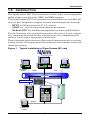
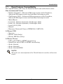
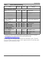
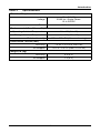
OpenComms NIC
MONITORING
USER MANUAL
TABLE OF CONTENTS
1.0
INTRODUCTION . . . . . . . . . . . . . . . . . . . . . . . . . . . . . . . 1
1.1
OpenComms Compatibility . . . . . . . . . . . . . . . . . . . . . . . 2
2.0
INSTALLATION . . . . . . . . . . . . . . . . . . . . . . . . . . . . . . . 5
2.1
2.2
2.3
Retrofit Kit . . . . . . . . . . . . . . . . . . . . . . . . . . . . . . . . . . . . 5
Self-Contained Unit . . . . . . . . . . . . . . . . . . . . . . . . . . . . . 5
User Connections for OpenComms NIC . . . . . . . . . . . . . 6
2.3.1
2.3.2
2.3.3
Network Port . . . . . . . . . . . . . . . . . . . . . . . . . . . . . . . . . . . . 6
BMS Port . . . . . . . . . . . . . . . . . . . . . . . . . . . . . . . . . . . . . . . 6
Configuration Port / Service Terminal . . . . . . . . . . . . . . . . 6
3.0
SYSTEM CONFIGURATION . . . . . . . . . . . . . . . . . . . . . . . 9
3.1
3.2
DIP Switch Settings . . . . . . . . . . . . . . . . . . . . . . . . . . . . . 9
Service Terminal . . . . . . . . . . . . . . . . . . . . . . . . . . . . . . . 9
4.0
OPERATION . . . . . . . . . . . . . . . . . . . . . . . . . . . . . . . . 14
4.1
4.2
4.3
SNMP . . . . . . . . . . . . . . . . . . . . . . . . . . . . . . . . . . . . . . . 14
Liebert Global Products MIB. . . . . . . . . . . . . . . . . . . . . 14
RFC 1628 UPS MIB . . . . . . . . . . . . . . . . . . . . . . . . . . . . 15
4.3.1
SNMP Traps . . . . . . . . . . . . . . . . . . . . . . . . . . . . . . . . . . . 15
4.4
4.5
4.6
4.7
4.8
MIB . . . . . . . . . . . . . . . . . . . . . . . . . . . . . . . . . . . . . . . . . 17
HTTP. . . . . . . . . . . . . . . . . . . . . . . . . . . . . . . . . . . . . . . . 17
Modbus RTU . . . . . . . . . . . . . . . . . . . . . . . . . . . . . . . . . . 17
System Reset . . . . . . . . . . . . . . . . . . . . . . . . . . . . . . . . . 17
Diagnostics . . . . . . . . . . . . . . . . . . . . . . . . . . . . . . . . . . . 18
5.0
MODBUS COMMUNICATIONS AND CONNECTIVITY . . . . . 19
5.1
Implementation Basics . . . . . . . . . . . . . . . . . . . . . . . . . 19
5.1.1
5.2
5.3
Constraints . . . . . . . . . . . . . . . . . . . . . . . . . . . . . . . . . . . . 19
Transmission Format . . . . . . . . . . . . . . . . . . . . . . . . . . . 19
Physical Connection . . . . . . . . . . . . . . . . . . . . . . . . . . . . 20
i
5.4
Modbus Slave Functions . . . . . . . . . . . . . . . . . . . . . . . . 21
5.4.1
5.4.2
5.4.3
5.4.4
5.4.5
5.4.6
5.4.7
5.5
Data Type. . . . . . . . . . . . . . . . . . . . . . . . . . . . . . . . . . . . . . 21
Function Code Support . . . . . . . . . . . . . . . . . . . . . . . . . . . 22
Read/Write Holding Registers (0x03, 0x06, 0x10) . . . . . . 22
Read Input Registers (0x04) . . . . . . . . . . . . . . . . . . . . . . . 22
Read, Set Coil Status (0x01, 0x05, 0x0F) . . . . . . . . . . . . . 22
Read Input Status (0x02) . . . . . . . . . . . . . . . . . . . . . . . . . 23
Error Handling . . . . . . . . . . . . . . . . . . . . . . . . . . . . . . . . . 23
RTU Framing Examples . . . . . . . . . . . . . . . . . . . . . . . . 24
5.5.1
5.5.2
Read Registers (Function Code 0x03 & 0x04) . . . . . . . . . 24
Write single holding register (Function Code 0x06) . . . . 24
6.0
NIC SETUP AND TESTING . . . . . . . . . . . . . . . . . . . . . . 25
6.1
6.2
6.3
6.4
6.5
6.6
Jumper Placement . . . . . . . . . . . . . . . . . . . . . . . . . . . . . 25
Testing the Network. . . . . . . . . . . . . . . . . . . . . . . . . . . . 26
Service Terminal Troubleshooting . . . . . . . . . . . . . . . . 26
SNMP Troubleshooting . . . . . . . . . . . . . . . . . . . . . . . . . 26
Web Troubleshooting . . . . . . . . . . . . . . . . . . . . . . . . . . . 27
Modbus Troubleshooting . . . . . . . . . . . . . . . . . . . . . . . . 27
7.0
FIRMWARE UPDATES . . . . . . . . . . . . . . . . . . . . . . . . . 28
7.1
7.3
Establishing Communication—Necessary
Components . . . . . . . . . . . . . . . . . . . . . . . . . . . . . . . . . . 28
Establishing Communication—Service Terminal
Settings . . . . . . . . . . . . . . . . . . . . . . . . . . . . . . . . . . . . . . 29
Firmware Update Procedure . . . . . . . . . . . . . . . . . . . . . 30
8.0
EXTERNAL ENCLOSURES . . . . . . . . . . . . . . . . . . . . . . 33
8.1
8.2
Power Connection. . . . . . . . . . . . . . . . . . . . . . . . . . . . . . 33
Communication Connection. . . . . . . . . . . . . . . . . . . . . . 33
9.0
RETROFIT INSTALLATION . . . . . . . . . . . . . . . . . . . . . . 34
9.1
Environmental Installation . . . . . . . . . . . . . . . . . . . . . . 34
7.2
9.1.1
9.2
Deluxe System/3 . . . . . . . . . . . . . . . . . . . . . . . . . . . . . . . . 34
System Wiring (SM, AM, AG Microprocessors) . . . . . . 37
ii
9.3
Power Connection (SM, AM, AG Microprocessors). . . . 37
9.3.1
9.3.2
9.3.3
9.4
Power Connection (Level 0 and Level 10
Microprocessors) . . . . . . . . . . . . . . . . . . . . . . . . . . . . . . . . 37
Communication Connection (SM, AM, AG
Microprocessor) . . . . . . . . . . . . . . . . . . . . . . . . . . . . . . . . . 38
Communication Connection (Level 0 and Level 10
Microprocessors) . . . . . . . . . . . . . . . . . . . . . . . . . . . . . . . . 38
Himod (LNA) . . . . . . . . . . . . . . . . . . . . . . . . . . . . . . . . . 38
9.4.1
9.4.2
9.4.3
9.5
9.6
9.7
9.8
System Wiring (Himod). . . . . . . . . . . . . . . . . . . . . . . . . . . 39
Power Connection (Himod) . . . . . . . . . . . . . . . . . . . . . . . . 39
Communication Connection (HiMod) . . . . . . . . . . . . . . . . 39
Mini-Mate2 . . . . . . . . . . . . . . . . . . . . . . . . . . . . . . . . . . . 39
Emerson Network Power (CEMS100 / LECS15) . . . . . 40
UPS Installation. . . . . . . . . . . . . . . . . . . . . . . . . . . . . . . 40
Npower . . . . . . . . . . . . . . . . . . . . . . . . . . . . . . . . . . . . . . 40
9.8.1
9.8.2
9.9
9.10
9.11
9.12
9.13
Power Connection for NPower . . . . . . . . . . . . . . . . . . . . . 40
Communication Connection for NPower . . . . . . . . . . . . . 40
7200 UPS . . . . . . . . . . . . . . . . . . . . . . . . . . . . . . . . . . . . 42
HiPulse UPS . . . . . . . . . . . . . . . . . . . . . . . . . . . . . . . . . . 44
Static Switch2. . . . . . . . . . . . . . . . . . . . . . . . . . . . . . . . . 46
STS . . . . . . . . . . . . . . . . . . . . . . . . . . . . . . . . . . . . . . . . . 47
PDU and DataWave with PMP & EPMP . . . . . . . . . . . 47
iii
FIGURES
Figure 1
Figure 2
Figure 3
Figure 4
Figure 5
Figure 6
Figure 7
Figure 8
Figure 9
Figure 10
Figure 11
Figure 12
Figure 13
Figure 14
Figure 15
Figure 16
Figure 17
Figure 18
Figure 19
Figure 20
Typical installation of OpenComms NIC card . . . . . . . . . . . . . . . 1
Connections . . . . . . . . . . . . . . . . . . . . . . . . . . . . . . . . . . . . . . . . . . 5
Null modem cable diagram . . . . . . . . . . . . . . . . . . . . . . . . . . . . . . 7
NIC main menu in HyperTerminal . . . . . . . . . . . . . . . . . . . . . . . 8
LED locations . . . . . . . . . . . . . . . . . . . . . . . . . . . . . . . . . . . . . . . . 18
Typical maximum installation . . . . . . . . . . . . . . . . . . . . . . . . . . 20
Exceeding maximum specifications . . . . . . . . . . . . . . . . . . . . . . 21
Jumper positions . . . . . . . . . . . . . . . . . . . . . . . . . . . . . . . . . . . . . 25
NIC-ENCL1 internal view. . . . . . . . . . . . . . . . . . . . . . . . . . . . . . 33
Deluxe System 3 NIC installation . . . . . . . . . . . . . . . . . . . . . . . 34
Deluxe System 3 chilled water control cavity . . . . . . . . . . . . . . 35
ICS control cavity. . . . . . . . . . . . . . . . . . . . . . . . . . . . . . . . . . . . . 35
Challenger installation location . . . . . . . . . . . . . . . . . . . . . . . . . 36
Himod NIC installation location . . . . . . . . . . . . . . . . . . . . . . . . . 38
NPower UPS NIC installation . . . . . . . . . . . . . . . . . . . . . . . . . . 41
7200 UPS NIC installation . . . . . . . . . . . . . . . . . . . . . . . . . . . . . 43
HiPulse installation . . . . . . . . . . . . . . . . . . . . . . . . . . . . . . . . . . . 45
STS2 typical NIC location . . . . . . . . . . . . . . . . . . . . . . . . . . . . . . 46
STS2 NIC installation, 800-1000A units . . . . . . . . . . . . . . . . . . 46
STS2 NIC installation, 100 - 600A units . . . . . . . . . . . . . . . . . . 47
TABLES
Table 1
Table 2
Table 3
Table 4
OpenComms availability . . . . . . . . . . . . . . . . . . . . . . . . . . . 3
Specifications . . . . . . . . . . . . . . . . . . . . . . . . . . . . . . . . . . . . 4
Service terminal navigation . . . . . . . . . . . . . . . . . . . . . . . . 10
Exception response . . . . . . . . . . . . . . . . . . . . . . . . . . . . . . . 23
iv
Introduction
1.0
INTRODUCTION
The OpenComms NIC Card transforms Liebert units into manageable
nodes within your Network, NMS, and BMS systems.
The OpenComms NIC Card contains a standard Ethernet and EIA-485
(2-wire) port designed to support viewing and management through:
• HTTP for Web browsers (I.E. 5.5 or later)
• SNMP (v1, v2c) for network management systems
• Modbus RTU for building management systems (and SiteScan)
For the first time, the system that monitors the status of your computing, communication and facility infrastructure can comprehensively
monitor your Liebert equipment concurrently.
These standard open protocols allow simple integration into your monitoring system, leveraging prior infrastructure investments and established procedures.
Figure 1
Typical installation of OpenComms NIC card
Internet Web
Browsers
Network
Management
Systems
SNMP
HTTP
ETHERNET
OpenComms NIC
Power
Air
Modbus
UPS
Building
Management
System
1
Introduction
1.1
OpenComms Compatibility
The OpenComms NIC may be installed and used with these units:
Environmental Units
• Deluxe System3—Advanced Microprocessor with Graphics,
Advanced Microprocessor and standard microprocessor
• Challenger 3000—Advanced Microprocessor with Graphics,
Advanced Microprocessor and standard microprocessor
• Mini-Mate2
• Level 00—Deluxe System3, Challenger 3000
• Level 10—Deluxe System3, Challenger 3000
• Level 05/15 (UK)
• Himod
• Emerson Network Power (CEMS100 / LECS15)
3-Phase UPS
• Npower
• Hiross 7200 (Italy)
• Hiross HiPulse (Italy)
3-Phase Power
• PDU with PMP or EPMP monitoring
• DataWave with PMP or EPMP monitoring
• Static Switch
• Static Switch2
• Static Switch2/PDU
NOTE
All units are manufactured in North America unless otherwise
noted.
2
Introduction
Table 1
OpenComms availability
Factory
Option
Retrofit
Kit
Deluxe System 3 and
ICS
Yes
Yes
NIC-K-SYS3
Challenger
Yes
Yes
NIC-K-CHALL
Unit
Retrofit Kit
Part #
Environmental Products
Mini-Mate2
Yes
Level 00/05/10/15
Himod
Emerson Network
Power (CEMS100 /
LECS15)
1
NIC-ENCL1 OR 2
Yes
NIC
Yes
Yes
NIC
Yes 3
Yes 3
Consult sales department
Yes
Yes 2
37OP000NIC8
Yes
Yes
2
4645114G
Yes
2
4645114d
3-Phase UPS
Npower
Hiross 7200 (Italy)
Hiross HiPulse (Italy)
Yes
3-Phase power
PDU DataWave With
PMP or EPMP
Yes 1,2
NIC-ENCL1 OR 2
Static Switch
Yes 1,2
NIC-ENCL1 OR 2
Static Switch 2
Yes 2
Yes
STSNIC
1
Requires an external enclosure assembly
Contact your sales / service representative or liebert global services for installation.
3 For Australian units, contact the international sales department @
[email protected]
2
Retrofit Kits are designed specifically for individual units. Consult
your local Emerson and Liebert sales representative for pricing, part
numbers and installation help.
3
Introduction
Table 2
Specifications
Electrical Requirements
Voltage
18 to 24VAC
50/60 Hz, Single Phase
12 to 36VDC
Power
6VA maximum
Environmental Conditions, °F (°C)
Operating Ambient Temperature
41 to 104 (5 to 40)
Storage Ambient Temperature
-4 to 140 (-20 to 60)
Relative Humidity
10% to 90% RH (Non-condensing)
Dimensions, Inches (mm)
Unit Only
7 x 4 x 1.5 (178 x 102 x 38)
As Shipped
9.75 x 7.0 x 2.5 (248 x 178 x 64)
Weight, lb (kg)
Unit Only
0.4 (0.2)
As Shipped
1.3 (0.6)
4
Installation
2.0
INSTALLATION
The OpenComms NIC card may be ordered as a factory-installed
option, and it may be installed as a kit for field retrofit to existing Liebert units or as a self-contained unit in its own enclosure.
If ordered as a factory-installed option, proceed to 2.3 - User Connections for OpenComms NIC.
2.1
Retrofit Kit
As a retrofit kit, the circuit board is secured to a metal mounting
plate. The mounting plate then is attached to a flat metal surface in a
low-voltage section of the Liebert unit.
2.2
Self-Contained Unit
The self-contained model packages the interface card inside a steel
enclosure, for mounting external to the Liebert unit. A low-voltage
transformer is also provided.
Figure 2
Connections
IGMnet or SiteScan
Comms from Unit
(input to TB1)
Input Power
(Input to TB3)
Modbus Output for BMS
(Output from TB2)
Network Port for
NMS and Web access
DTE Serial Port
for Configuration
5
Installation
2.3
User Connections for OpenComms NIC
The OpenComms NIC can use simultaneous connections, sometimes
requiring three user connections:
• Permanent network connection
• Modbus 485 connection
• Temporary serial connection for configuration/setup
2.3.1
Network Port
Consult with the network administrator or other responsible party for
arranging a network drop to the Liebert equipment. The OpenComms
NIC communicates via standard 10 Base-T Ethernet network connection. Route the 10 Base-T cable to the Liebert unit and connect to J3,
the RJ45 jack on the interface card. The OpenComms Network card
will operate with any 10 Base-T Ethernet, regardless of operating system used.
2.3.2
BMS Port
The Modbus 485 connection will use the terminals marked “Repeater.”
(TB2) The Modbus server uses RTU protocol and will allow for a maximum of 32 units on 4000ft. of wire on a common line. EIA-485 repeaters may be necessary to accommodate additional units or longer
cables. Point availability may be referenced in the document, “NIC
Reference Library,” which may be downloaded at www.liebert.com
under the OpenComms product family.
2.3.3
Configuration Port / Service Terminal
A temporary serial connection to the interface card is necessary for
configuration and setup.
Using a DB9F-DB9F null-modem cable, connect the “DTE Serial Port”
P18 to an ASCII terminal or computer running terminal emulation
application. HyperTerminal® and Procomm® are examples of terminal emulation applications running on Microsoft Windows® operating
systems. All trademarks are property of their respective owners.
6
Installation
Accessing the Configuration Port
What you will need:
• PC capable of running a terminal emulation application, such as
Microsoft Windows® HyperTerminal®.
• DB9 Null modem or file transfer cable. (The correct cable will have
at a minimum, pins 2 and 3 crossed at the ends.) Null modem
cables are commonly found in computers stores and may also be
referred to as a file transfer cable.
Figure 3
Null modem cable diagram
DTE Device
Receive Rx (pin2)
Null Connection
Transmit Tx (pin3)
DTE Device
Receive Rx (pin2)
Transmit Tx (pin3)
NOTE
Turn off the power management on your PC or laptop to ensure
that the communications port will not “go to sleep” during the
configuration process.
1. Launch HyperTerminal. When you see the
screen at right, select Cancel.
2. Select the disconnect icon from the menu bar.
This step ensures that you will be able to
modify the configuration settings.
3. Go to File > Properties to make
configuration changes. Under the Connect
To setting, choose the appropriate communications port for your
computer. Generally this is Com 1.
4. Select the Configure button
and adjust the terminal
communication settings to:
• Bits per second: 9600
• Data Bits: 8
• Parity: None
• Stop Bit: 1
• Flow Control: None
• Select OK to close both windows.
5. After the communication
settings are adjusted, press
7
Installation
the Enter key on your keyboard. This will initiate
communications with the card and the following screen should be
displayed.
Figure 4
NIC main menu in HyperTerminal
(You can also cycle power on the OpenComms NIC card. This will
also initiate communications and provide information on current
revision status.)
6. When the message “Initializing Network…” appears, hit the
Enter key on your keyboard. (Additional network information
may appear)
!
CAUTION
Cycling power on either the 7200 or the HiPulse UPS is not
recommended unless the unit is in bypass mode. Consult the
UPS user manual for further instructions.
8
System Configuration
3.0
SYSTEM CONFIGURATION
3.1
DIP Switch Settings
A four-position DIP switch is provided, but no user configuration via
DIP switches is necessary at this time.
3.2
Service Terminal
Refer to Accessing the Configuration Port on page 7 for explicit
details on accessing the service terminal / configuration port.
By default, the service terminal communication parameters are:
• 9600 bps
• No parity
• 8 data bits
• 1 stop bit
• Flow Control: None
After connecting to the OpenComms NIC card, press the space bar or
<Enter> key to activate the service terminal session. If no response is
apparent and you have verified connectivity, cycle power on the OpenComms NIC and the service terminal sessions should appear automatically.
!
CAUTION
Cycling power on either the 7200 or the HiPulse UPS is not
recommended unless the unit is in bypass mode. Consult the
UPS user manual for further instructions.
9
System Configuration
Table 3
Service terminal navigation
Main Menu
1. System Information
1.1 Name
1.2 Contact
1.3 Location
1.4 Description
2. Network Settings
2.1 Boot / IP Settings
2.1.1 Boot Mode
2.1.1.1 Static
2.1.1.2 BootP
2.1.1.3 DHCP
2.1.2 IP Address
2.1.3 Netmask
2.1.4 Default Gateway
2.2 SNMP Communications
2.2.1 SNMP agent (enable/disable)
2.2.2 Authentication Traps (enable/disable)
2.2.3 Display / Modify Communities
2.2.4 Display / Modify Trap Communities
2.3 Web Server
2.3.1 Web Server (enable/disable)
2.3.2 Configuration Control (enable/disable)
2.3.3 Refresh rate
2.4 Telnet Server
2.4.1 Telnet server (enable/disable)
2.5 Change User Name / Password
2.5.1 Enter User Name (prompt)
2.5.2 Enter New Password (prompt)
2.5.3 Verify Password (prompt)
3. Firmware Updates
3.1 Initiate Xmodem Session
4. Factory Settings
4.1 Reset to Factory Defaults [y/n]
4.1.1 Manufacture Date
4.1.2 MAC Address
4.1.3 Serial Number
4.1.4 Boot Version
4.1.5 App Version
4.1.6 Hardware Version
5. Auxiliary Communications
5.1 Enable Application [y/n]
5.1.1 None
5.1.2 Modbus Server
5.1.2.1 Enabled Application
5.1.2.2 Control (enabled/disabled)
5.1.2.3 Server ID
5.1.2.4 Communications Rate (9600 fixed)
Q: Quit and abort changes
X: Exit and save
10
System Configuration
System Information Menu
The System Information Menu seeks descriptive input to enable the
unit to be identified. This data is readable via SNMP queries. The (“)
character is not permitted in any of the descriptive fields
Network Settings Menu
The Network Settings Menu configures network parameters essential
for proper network operation. The network administrator or other personnel responsible for the network should be consulted for the proper
parameters to be entered in this menu.
In the static mode, the IP address is entered. Use the standard fourpart dotted decimal format. The NetMask and Default Gateway
should also be entered in dotted decimal format. The NetMask, also
known as subnet mask, delineates devices on the same physical network segment, versus devices that require the services of a network
router for access to other networks. The Default Router is the address
of default router on the local segment.
!
CAUTION
Consult your network administrator to ascertain the
parameters appropriate to your network.
BOOTP and DHCP Mode
The OpenComms NIC supports DHCP and BOOTP if a DCHP or
BOOTP server must exist on the network. When this feature is
enabled, at boot-up the card will perform a DHCP or BOOTP request
for configuration information, including automatic assignment of an
IP address. If the card receives the information, no further requests
are made. If, at boot-up, a response is not received, the card will continue to send a request approximately every 30 seconds until a
response is received. When this condition is encountered, pushing the
<Enter> key returns the unit to the service terminal mode.
SNMP Communications Menu
The SNMP (Simple Network Management Protocol) Communications
Menu specifies parameters particular to the SNMP interface. Communities are used as a means of security for SNMP v1; only specified
hosts with the appropriate community name(s) are allowed to perform
particular SNMP operations. Up to 20 different communities can be
assigned.
For each community, specify the dotted decimal IP address of the
remote host, the privilege level (read or read/write), and community
name. Trap Communities specify the recipient(s) of SNMP trap messages generated by the OpenComms Network Interface Card. Typically; the recipient is the management station of the NMS. Specify the
11
System Configuration
destination IP address, and the community name for that host. Up to
20 trap communities can be assigned. For Communities and Trap
Communities, the information can be entered as a “complex” line —
all parameters space-delimited on the command line. Otherwise, the
menu items will prompt for each individual parameter.
NOTE
SNMP v1 communities are transmitted in plain (unencrypted)
text across the network.
Authentication failure traps may be enabled, so that the network
management system can be warned when unauthorized access (i.e.:
incorrect community name) is attempted.
Web Server
The Web Server section will allow the user to disable / enable the
HTTP session for the card. Disabling the Web Server means that web
browsers will not be able to access the devices status graphical page
(GUI).
Telnet
This section allows users to enable or disable the Telnet session.
Change User Name / Password
This section allows users to set or change the default user name and
password.
• Default user name is “Liebert” (case sensitive).
• Default password is “Liebert” (case sensitive).
Firmware Updates Menu
The Firmware Update Menu is intended for Liebert service personnel only. No
user configurable parameters are accessed in this selection. If entered, to escape,
power must be cycled on the card.
Factory Settings Menu
The Factory Settings Menu displays the manufacture date, serial
number and MAC address of the card. These parameters are readonly. Once all parameters have been entered, press Escape to return
to the Main menu; then press x to save configuration, exit and reboot
to enable the new configuration. All parameters are stored in non-volatile flash memory. Pressing q after Escape will abort all changes.
Neither selection is case-sensitive.
12
System Configuration
Auxiliary Communications
The Auxiliary Communications Menu allows the user to set up the
parameters necessary for Modbus communications. The user can
enable / disable the Modbus sessions as well as assign the slave ID.
Q. <q> will abort all changes.
X. <x> will save configuration changes.
Once all parameters have been entered, press <escape> to return
to the Main menu; then press exit and reboot using the new configuration. All parameters are stored in non-volatile flash memory.
Neither selection is case-sensitive.
13
Operation
4.0
OPERATION
4.1
SNMP
The OpenComms Network Interface Card supports “get,” “getnext,”
“set,” “response” and “trap” packets of SNMP (Simple Network Management Protocol). The OpenComms NIC supports MIB-II, RFC1628
and Liebert Global Products MIBs. The terms “alarms” and “conditions” will be used interchangeably through out this description.
Alarms are generated and maintained through the RFC 1628 UPS
MIB. Conditions are generated and maintained through the Liebert
Global Products MIB.
The RFC 1628 UPS MIB provides information for the supported UPS
devices. The Liebert Global Products MIB provides information for the
supported environmental devices. All conditions that are listed are
dependent upon what the unit itself supports. When a condition
occurs within the unit, it is logged into the condition table within the
appropriate MIB and a unique ID is assigned. A description of the condition along with the value of the system up-time when the condition
was generated is placed into the table as well. A trap is then sent out
to the monitoring system.
4.2
Liebert Global Products MIB
Environmental units log conditions in the Liebert Global Products
MIB. Traps for the environmental units are generated out of the Liebert Global Products MIB. Currently, there are only two traps that are
sent for environmental units through the MIB: Event Condition Entry
Added and Event Condition Entry Removed. The Event Condition
Entry Added is sent each time a condition is inserted into the conditions table. This trap provides the condition ID, the condition description, and the condition time. The Event Condition Entry Removed is
sent each time a condition is removed from the conditions table. This
trap provides the condition ID, the condition description, and the condition time.
14
Operation
4.3
RFC 1628 UPS MIB
UPS units log alarms in the RFC 1628 UPS MIB. Traps for the UPS
units are generated out of the RFC 1628 UPS MIB. There are four
traps that may be sent for the UPS units: Trap On Battery, Trap Test
Completed, Trap Alarm Entry Added and Trap Alarm Entry Removed.
The trap On Battery is sent when the UPS is operating on battery
power. This trap will be sent once a minute until the UPS either shuts
down or is no longer running on battery power. This trap provides the
Estimated Minutes Remaining on Battery, the Seconds on Battery
and the Configured Low Battery Time. The Trap Test Completed is
sent when a UPS diagnostic test is completed. This trap provides the
Test ID of the test that has been performed, the Test Spin Lock, the
Test Results Summary, the Test Results Detail, the Test Start Time
and the Test Elapsed Time. The Trap Alarm Entry Added is sent
when an alarm is placed into the alarm table and provides the alarm
ID and the alarm description. This trap is not sent on the following
alarms: On Battery and Test In Progress. The Trap Alarm entry
Removed is sent when an alarm is removed from the alarm table and
provides the alarm ID and the alarm description. This trap is not sent
out when the Test In Progress alarm is removed from the alarm table.
4.3.1
SNMP Traps
Below is the definition on how events are handled in RFC1628.
* Two similar event traps (notifications) are sent to their destination
or NMS system. The event traps are differentiated by their trap type.
Type 3 = Condition ADDED to the event table, Type 4 = Condition
REMOVED from the event table.
*Each event trap contains the following three bindings of information:
1. Trap ID. The ID represents the location or placeholder in the table
to find event information.
2. The OID reference of the well-known alarm. Note: Below are the
OID references for RFC1628 alarms. These are not Liebert-unit
specific, but rather RFC1628 specific.
3. Time ticks or system uptime that represents when an event
occurred.
15
Operation
[OIDALARMS]
1.3.6.1.2.1.33.1.6.3.1:upsAlarmBatteryBad{}
1.3.6.1.2.1.33.1.6.3.2:upsAlarmOnBattery{}
1.3.6.1.2.1.33.1.6.3.3:upsAlarmLowBattery{}
1.3.6.1.2.1.33.1.6.3.4:upsAlarmDepletedBattery{}
1.3.6.1.2.1.33.1.6.3.5:upsAlarmTempBad{}
1.3.6.1.2.1.33.1.6.3.6:upsAlarmInputBad{}
1.3.6.1.2.1.33.1.6.3.7:upsAlarmOutputBad{}
1.3.6.1.2.1.33.1.6.3.8:upsAlarmOutputOverload{}
1.3.6.1.2.1.33.1.6.3.9:upsAlarmOnByPass{}
1.3.6.1.2.1.33.1.6.3.10:upsAlarmBypassBad{}
1.3.6.1.2.1.33.1.6.3.11:upsAlarmOutputOffAsRequested{}
1.3.6.1.2.1.33.1.6.3.12:upsAlarmUpsOffAsRequested{}
1.3.6.1.2.1.33.1.6.3.13:upsAlarmChargerFailed{}
1.3.6.1.2.1.33.1.6.3.14:upsAlarmUpsOutputOff{}
1.3.6.1.2.1.33.1.6.3.15:upsAlarmUpsSystemOff{}
1.3.6.1.2.1.33.1.6.3.16:upsAlarmFanFailure{}
1.3.6.1.2.1.33.1.6.3.17:upsAlarmFuseFailure{}
1.3.6.1.2.1.33.1.6.3.18:upsAlarmGeneralFault{}
1.3.6.1.2.1.33.1.6.3.19:upsAlarmDiagnosticTestFailed{}
1.3.6.1.2.1.33.1.6.3.20:upsAlarmCommunicationsLost{}
1.3.6.1.2.1.33.1.6.3.21:upsAlarmAwaitingPower{}
1.3.6.1.2.1.33.1.6.3.22:upsAlarmShutdownPending{}
1.3.6.1.2.1.33.1.6.3.23:upsAlarmShutdownImminent{}
1.3.6.1.2.1.33.1.6.3.24:upsAlarmTestInProgress{}
To summarize, event traps generally are parsed by the NMS for any of
the information contained in the trap. A process should be put in place
by the NMS to recognize whether the event trap is a new condition or
a cleared condition by looking at the trap type. Likewise, the NMS
should be able to extract the second binding of the trap notification to
see the OID of the well-known alarm. This OID reference will allow
the NMS to extract the well-known name or description of the event.
16
Operation
4.4
MIB
The Management Information Base (MIB) is a formal document
declaring the specifics of the information supported by the SNMP
implementation. The administrator for the NMS (or other applications
utilizing SNMP to communicate with the Liebert units will need the
MIB in order to integrate the Liebert units into the monitoring system.
The MIB files are contained on the CD that ships with the product.
Alternatively, the MIBs for the OpenComms Network Interface Card
are available for download at www.liebert.com. Navigate through
Products, then Site Monitoring & Software and proceed to the OpenComms support information area. The RCF 1628 MIB can be downloaded at www.ietf.org.
4.5
HTTP
Status and alarm information can be queried by Web browsers via
HTTP v1.1 (Hyper Text Transfer Protocol). The data is shown in an
intuitive graphical format, akin to the unit’s front bezel controls.
These browsers have been tested and are supported:
• Microsoft Internet Explorer, versions 5.x and later
• Limited Support for: Netscape 6.0 & Opera 5
Font size may need to be adjusted on your browser for optimal viewing.
With appropriate NMS software and configuration, the user on reception of SNMP traps may view HTTP pages in order to view the overall
operating status of the unit – or HTTP may be used on its own to monitor “on-demand” the unit operation. HTTP pages will automatically
refresh (reload) every 20 seconds and is adjustable through the service
terminal program.
4.6
Modbus RTU
See 5.0 - Modbus Communications and Connectivity for a complete explanation of the Modbus slave.
4.7
System Reset
The OpenComms Network card contains an on-board real time clock
and watchdog circuitry. The card is self-monitoring and self-correcting. However, a push button is provided to permit a manual system
reset. The reset push button is labeled S1 on the interface card: press
and hold it for 3 seconds before to releasing to initiate hardware reset.
17
Operation
4.8
Diagnostics
A number of LEDs are provided on the interface card to provide information for diagnostic purposes. The following table summarizes their
indications:
LED
Identifier
Description
DS1
Ethernet Port Collision
DS2
Ethernet Port Receive
DS3
Ethernet Port Transmit
DS4
Ethernet Port Link
DS5
Not used
DS6
Not used
DS7
Repeater Port Receive
DS8
IGM Port Receive
DS9
Microprocessor in Operation
DS10
Serial Port Receive
DS11
Serial Port Transmit
DS12
Repeater Port Transmit
DS13
IGM Port Transmit
DS14-19
Not used
Figure 5
LED locations
DS8
DS9
DS8
DS13
18
Modbus Communications and Connectivity
5.0
MODBUS COMMUNICATIONS AND CONNECTIVITY
This section describes the Modbus communications protocol as supported by the OpenComms NIC card. It includes information on how
to pass information to and from the OpenComms NIC card via Modbus. It is also intended to help facilitate answering questions regarding supported types, frame format, function code support etc.
5.1
Implementation Basics
Protocol controls the language structure or message format between
devices in other words, the rules for communication. The rules for
communication include how master and slave devices initiate communications, as well as unit identification, message handling and error
checking. Modbus protocol simply refers to the control of the query
and response cycles between master and slave devices.
The OpenComms NIC module is configured to act as a slave device on
a common network. The common network is a multi-drop or “daisy
chain” configuration over EIA-485, where multiple slaves reside on a
common wire or loop.
5.1.1
Constraints
The OpenComms NIC communicates with local database and therefore is subject to the time delay resulting from the local database
updating policies. Use of “Preset Multiple Holding Registers” and
“Preset a single Holding Register” functions requires accessing the
Liebert device connected and to the OpenComms NIC card database
service. Users should be aware that the Modbus application coexists
with other on-board application servers (HTTP and SNMP specifically) and competes for the database service and CPU time. This may
lead to uncertainty of responding time of the OpenComms NIC. The
user or third party integrator may have to compensate for the delay
time if HTTP, SNMP and Modbus are going to be utilized simultaneously.
5.2
Transmission Format
The OpenComms NIC module supports Modbus RTU (Remote Terminal Unit) transmission modes. The OpenComms NIC communication
rate is fixed at 9600 baud, 8 data bits, No parity, 1 Stop bit. The communication media is fixed using EIA-485 standards.
19
Modbus Communications and Connectivity
5.3
Physical Connection
A Modbus network should consist of one, and only one, host client, and
up to 255 slaves uniquely identifiable by their slave ID. The slave ID
of each OpenComms NIC is set through the service terminal (configuration) port. (See section 3, System Configuration for more details.)
The OpenComms NIC supports multi-drop connection over RS485. On
the OpenComms NIC, a client should connect to the OpenComms NIC
as a multi-drop connection via the RS485 “Repeater” port (TB2), (Pin1
as minus and Pin2 as plus. J28-1 and J28-2 should be shorted.)
The OpenComms NIC card is designed to reside on a maximum common line of 32 devices with a total cable length of 4000 feet. In a “normal environment” all devices should be connected in “daisy-chain”
fashion, with “star configurations” or branches, being used at a minimum. See Figure 6 for details. A “normal environment” consists of an
installation where noise or electrical interference is minimal. This is
typical of communication wiring run in properly grounded conduit or
in areas where high voltage or radio transmissions are not present.
Otherwise, these conditions are designated as “noisy.”
Figure 6
Typical maximum installation
Modbus RTU Master
EIA-485 9600,N,8,1
Maximum of 32
devices with combine
cable length of 4000
feet
The recommended cable characteristics are:
Normal Environments:
• 18-22 gauge, twisted-pair, stranded (non- shielded)
Typical type is: Belden 8442
Noisy Environments:
• 18-22 gauge, twisted-pair, stranded (shielded)
Typical type is: Belden 9461
20
Modbus Communications and Connectivity
Figure 7
Exceeding maximum specifications
Modbus RTU Master
EIA-485 9600,N,8,1
Maximum of 32
devices with combine
cable length of 4000
feet
R
Modbus RTU Master
EIA-485 9600,N,8,1
R
Maximum of 32
devices with combine
cable length of 4000
feet
The maximum specification may be exceeded if measures are taken to
drive or boost the EIA-485 communication line. Two wire EIA485
repeaters are available through the Liebert Corporation. SiteScan’s
“REPOPT” will work sufficiently for this application. Consult the
SiteScan price book for pricing schedule and alternative solutions.
5.4
Modbus Slave Functions
5.4.1
Data Type
The OpenComms NIC supports data in a register block as one of the
following types: Signed integer (16 bit) / Unsigned integer (16 bit) /
Signed long (32 bit); IEEE floating-point (32 bit); Null terminated
String.
A datum should consist of one or multiple registers. The leftmost byte
contains the MSB and the rightmost byte contains the LSB.
21
Modbus Communications and Connectivity
5.4.2
Function Code Support
The OpenComms NIC implements the following Modbus functions.
However, integrators will use function code 0x03, and 0x06 most often
due to the type of data to be acquired.
0x01
Read Coil Status
0x02
Read Input Status
0x03
Read Holding Registers
0x04
Read Input Registers
0x06
Write Single Holding Register
0x0F
Force Multiple Coils
0x10
Preset Multiple Holding Registers
5.4.3
Read/Write Holding Registers (0x03, 0x06, 0x10)
A holding register is a 16-bit message unit. In principle, a message in
a holding register is write / readable, but holding registers can be used
by read-only data as well. Holding registers are mapped into
40001-49999 logic address range.
Holding registers can be read by function code 0x03. A maximum of
125 registers can be read by a single query.
Function code 0x06 requests the server to change the content of a single holding register, and function code 0x10 requests server to change
the contents of multiple holding registers adjacent to each other.
5.4.4
Read Input Registers (0x04)
The input register block contains read-only data accessible to the user.
A datum in the input register block occupies one or multiple registers
such as described in the previous section. The input registers are
mapped into 30000-39999 of the logic address range.
Up to 125 input registers can be read by a single query using function
code 0x04.
5.4.5
Read, Set Coil Status (0x01, 0x05, 0x0F)
Coil status contains bit-mapped status accessible to the users. In principle, a coil status can be read, set or cleared by the host client. Multiple coil status can be read by specifying the index of bits of the first
coil and the number of consecutive coils in a single query.
Coil status can be read by function code 0x01.
Function code 0x05 set or clear a single coil, and function code 0x0F
set or clear multiple coils.
22
Modbus Communications and Connectivity
5.4.6
Read Input Status (0x02)
The input status block contains read-only status accessible to the
users. It can be read by using function code 0x02 in the same as reading coil status.
5.4.7
Error Handling
According to the Modbus specification, the OpenComms NIC composes
the following exception responses to the client if an exception or error
occurs.
Table 4
Exception response
Server
Address
Function Code
(0x80)
Exception
Code
16 Bit
CRC
1 byte
1 byte
1 bytes
2 bytes
Exception codes are:
• 01: Unsupported function code
• 02: Out-of-range data addresses
• 03: Out-of-range data value (write to holding registers)
• 04: There is currently no LMD device connected to the server
• 05: Server is composing response but cannot response to the client
within the time limit required by Modbus specification.
Modbus Packet Formats
Each Modbus packet consists of the following fields:
• Device Address
• Function Code
• Data Field(s)
• Error Check Field
Device Address
The address field immediately follows the beginning of the frame and
consists of 8-bits. These bits indicate the user assigned address of the
slave device that is to receive the message sent by the attached master
device.
Each slave OpenComms NIC must be assigned a unique address and
only the addressed slave will respond to a query that contains its
address.
Function Code
The function code field tells the addressed slaves what function to perform. Function codes are specifically designed invoke a specific action
by the slave device. The function code range is from 1 to 127. However,
23
Modbus Communications and Connectivity
the OpenComms NIC module primarily uses Function Code 3 (Read
Holding Registers) and Function Code 6 (Preset Single Register).
Data Field(s)
The data field varies in length depending on whether the message is a
request or a response to a packet. This field typically contains information required by the slave device to perform the command specified
or to pass back data to the master device.
Error Check Field
The Error Check Field consists of a 16-bit (2 byte) Cyclical Redundancy Check (CRC16). It allows the receiving device to detect a packet
that has been corrupted with transmission errors.
5.5
RTU Framing Examples
5.5.1
Read Registers (Function Code 0x03 & 0x04)
Query: for reading holding /input registers (requested by a client)
Server
Address
Function Code
(0x3/0x4)
Index of
starting register
Number of
registers to
be read
16 bit
CRC
1 byte
1 byte
2 bytes
2 bytes
2 bytes
Response: for reading holding/input registers (response by the
server)
Server
Address
Function Code
(0x3/0x4)
Byte
Count
Data from
registers
16 bit
CRC
1 byte
1 byte
1 byte
2*m bytes (= Byte Count)
2 bytes
5.5.2
Write single holding register (Function Code 0x06)
Query: for writing a single holding register (requested by a client)
Server
Address
Function Code
(0x06)
Index of
the register
16 bit value
to be written
16 bit
CRC
1 byte
1 byte
2 bytes
2 bytes
2 bytes
Response: for writing a holding registers (response by the server)
Server
Address
Function Code
(0x06)
Index of
the register
16 bit value
been written
16 bit
CRC
1 byte
1 byte
2 bytes
2 bytes
2 bytes
24
NIC Setup and Testing
6.0
NIC SETUP AND TESTING
The NIC has a specific setup that must be in place before the card will
function properly. There are jumpers on the board that must be in the
correct locations. The positions of these jumpers are numbered on the
board itself. A small triangle silk screened on the board represents
pin 1 for each set of pins to which jumpers may be applied.
6.1
Jumper Placement
J13, J14, and J18 on the board must have jumpers installed on them.
J32 must have a jumper installed on pins 2 and 3.
J28 jumper positions will apply to future capabilities, but are not currently usable on the NIC.
Your card was shipped with the jumpers properly installed.
Figure 8
Jumper positions
J18
J14
J13
J28
J32
25
NIC Setup and Testing
6.2
Testing the Network
“Ping” is a tool used to test the network. At the command prompt,
type, “ping <address of card>”. Ping will respond that it received a
reply from the card if the card is functioning properly on the network.
If the card is not functioning properly or is not connecting to the network, ping will respond that the request it sent to the card has timed
out.
If the ping request times out, go to the Service Terminal to verify that
the card initialized the network when it powered up. If the card is sitting at the text “Initializing network…” then the card has not connected to the network. Hit <enter> to go into the Service Terminal.
Select No. 2 for the Network Interface Menu. Verify that you have the
boot mode set up correctly. If you choose a static IP Address, verify
that the IP Address is valid for your network.
If you obtain your network information from a BootP or DHCP server,
verify that the server is valid and that it is responding to requests.
Once the information has been verified, press <escape> to return to
the main menu and select “x” to exit out of the card. Then, reboot the
card. The card may be rebooted by pressing switch S1 on the card for
approximately 2 seconds until the DS9 link light turns off.
If the card still does not connect to the network, or ping still does not
receive a reply from the card, verify proper set up on the card itself.
DS4 should be illuminated if the card detects the network. Verify that
the network cable is connected to Ethernet port J3 and that the hub/
router/switch to which the card is connected is operating correctly.
Once this information is verified, reboot the card.
6.3
Service Terminal Troubleshooting
If the card does not bring up a Service Terminal, check link light DS9.
DS9 should be illuminated within approximately 0.5 seconds of application of power. If DS9 is not illuminated and no other LED's are on,
verify that power has been applied to the card. If power has been
applied, verify wiring connected to TB3 is correct. TB3 should have
24VAC or 12 VDC applied. Reboot the card once the power to the card
has been verified.
6.4
SNMP Troubleshooting
If SNMP is not functioning, first make sure that the card powers up,
the Service Terminal is functioning and the card is connected to the
network (verified by using ping). If all of those conditions are met, verify that the community strings are set up correctly. To do this, go into
the Service Terminal and select number 3 for SNMP Communications.
26
NIC Setup and Testing
Then, select number 2 for Display/Modify Communities. Verify that
the IP Addresses listed are valid for your network. Verify that you are
typing in the correct community name when trying to access SNMP.
The community name is case sensitive.
Once this information is verified, reboot the card and try to access
SNMP again.
6.5
Web Troubleshooting
If the card does not serve up a web page, but the Service Terminal is
functioning, SNMP is functioning, and the card is connected to the
network (verified through ping), then reboot the card. In this case, the
web server has been lost and needs to be restarted.
If the card serves up a web page, but the web page only displays “Discovering connected device…” verify that the card is connected to the
desired device. Verify that the link lights DS13 and DS8 are blinking
on and off. DS13 indicates that the card is receiving from the connected device. DS8 indicates that the card is transmitting to the connected device.
If neither of the link lights is blinking, check the connection between
TB1 and P3. TB1 is used to interface to the Environmental units and
to some UPS’s. P3 is used to interface with some UPS’s. If DS13 is
blinking and DS8 is not, this indicates a communication problem
between the card and the connected device.
When this occurs, replace the NIC card and retry connecting to the
Web. If the problem persists, change the card in the device that the
NIC card is trying to interface with. Try to reconnect to the Web.
6.6
Modbus Troubleshooting
If the card does not respond to Modbus requests, verify that DS7,
“repeater port receive” is flashing during a request. In proper communications DS12 will also be flashing indicating, “repeater port transmit.”
Verify proper wiring on the EIA 485 network. OpenComms NIC cards
should observe a “plus to plus” and “minus to minus” daisy chain configuration.
Also verify that the proper slave ID has been set in service terminal.
Refer to 3.2 - Service Terminal for initiating a service terminal session.
27
Firmware Updates
7.0
FIRMWARE UPDATES
The firmware in the OpenComms NIC card can be updated to take
advantage of the latest release of software that may contain feature
enhancements, new unit compatibility or service patches. The firmware is updated through the OpenComms NIC cards’ serial port, using
a terminal emulation program like HyperTerminal in MS Windows
Operating Systems. This procedure has multiple steps and requires
that 3 files be downloaded to the OpenComms NIC card. The latest
firmware can be found at this link on the Liebert Web site:
http://www.liebert.com/dynamic/displayproduct.asp?id=998&cycles=60Hz
!
7.1
CAUTION
Read all instructions before to attempting a firmware
download.
Establishing Communication—Necessary
Components
• PC capable of running a terminal emulation application, such as
HyperTerminal.
• DB9 null modem or file transfer cable. (The correct cable will have
at a minimum, pins 2 and 3 crossed at the ends.)
• Firmware update files (3 files total with extensions of .s19)
NOTE
Turn off the power management on your PC or laptop to ensure
that the communications port will not “go to sleep” during the
upgrade process and corrupt the firmware on the OpenComms
NIC.
28
Firmware Updates
7.2
Establishing Communication—Service Terminal
Settings
1. Launch HyperTerminal. Once
you see the following screen,
select Cancel.
2. Select the disconnect icon
from the menu bar
. This
step ensures that you will be
able to modify the configuration
settings.
3. Go to File > Properties to make
configuration changes. Under
the Connect To setting, choose
the appropriate communications
port for your computer. Generally this is Com 1.
4. Select the Configure button and adjust the terminal
communication settings to:
• Bits per second: 9600
• Data Bits: 8
• Parity: None
• Stop Bit: 1
• Flow Control: None
5. Select OK to close both windows.
29
Firmware Updates
7.3
!
Firmware Update Procedure
CAUTION
The firmware download process is timed. After the firmware
download is initiated as described below, the user has
approximately 1 minute to finish initialization. Before
beginning the download, determine the location of the
firmware files so that the download can be completed within
the time constraints.
1. After the communication settings are
adjusted, press the Enter key on your
keyboard. This will initiate
communications with the card and display
the screen at right.
You can also cycle power on the OpenComms NIC card. This action will also initiate communications and provide
information on current revision status.
Once the “Initializing Network…” line
appears, hit the Enter key on your keyboard. (Additional network information
may appear.)
2. Select the option for Firmware Updates.
Only 1 selection is offered. Press 1.
3. When asked “Are you sure…” press Y.
4. 9.) Select the option to change the card’s
communication rate to 115200 bps. The prompt line will advise
you of the baud rate change.
5. End the HyperTerminal session and adjust the communication
rate to match the card.
6. Pressing Enter will reestablish communication
with the card. This will
display the screen at right.
7. Pressing Enter again will
initiate the file download
process. The screen at
right should appear.
30
Firmware Updates
8. When the above prompt is
displayed, start the file download
process by selecting Transfer –
Send File… from the
HyperTerminal menu, as shown at
right.
9. Select Xmodem for the Protocol
and browse to locate the file
OCNIC_REVx.x00.0_BLDxxx_FILE1.s19.
10. Click on Send in the dialog box.
NOTE
Do not press any keys on your keyboard or the firmware
download will abort.
11. The screen at right will appear
when the download begins. The
screen will display the
download progress,
disappearing when the
download is complete.
12. Once the file has completed
downloading, a prompt will ask
whether you with to continue.
Select Y to continue.
13. Select option 2 for Xmodem1K to
facilitate a faster download for the
remaining files. Press Enter twice
to initiate the download of the
second firmware file.
14. Select Transfer – Send File… from
the HyperTerminal menu.
15. Select 1K Xmodem for the protocol and browse to the location of:
OCNIC_REVx.x00.0_BLDxxx_FILE2.s19
16. Select Send; a progress prompt will be displayed.
Repeat Steps 11 through 16 to download the third firmware file. It is
named OCNIC_REVx.x00.0_BLDxxx_FILE3.s19
The last file is the largest of the three and will take approximately 20
minutes to download.
31
Firmware Updates
Once the last file is downloaded,
the screen at right will appear.
Repeat Steps 2 through 4 to
change the baud rate back to 9600 bps as
show in the illustration below right.
After the communication settings are
adjusted, hit the Enter key on your keyboard. The screen at right will appear.
You can also cycle power on the OpenComms NIC card. This action will also
initiate communications and provide
information on current revision status.
Once the “Initializing Network…” line
appears, hit the Enter key on your keyboard.
Select X and the card will reboot.
To ensure that the latest firmware is
downloaded to the OpenComms NIC
card, cycle power by removing and
restoring the power connection at TB3.
The information below will appear.
32
External Enclosures
8.0
EXTERNAL ENCLOSURES
8.1
Power Connection
Power for the OpenComms Network card should be sourced from the
supplied wall-plug transformer. Use field-supplied wiring to connect
the outer terminals on the transformer to the screw connectors at TB3
on the Network Interface card. A field-supplied ground wire attaches
to the center terminal on the transformer and connects to the grounding stud in the lower corner of the enclosure.
Figure 9
NIC-ENCL1 internal view
To SiteScan
connection
terminals on unit
Field-supplied
use 18AWG
8.2
Refer to specific unit installation
communication connection
Communication Connection
Communications to the OpenComm Network Card is generally established by using the unit’s SiteScan interface port. The specifics on
location and wiring details can be found in the respective unit’s user
manual.
The unit’s communications port is EIA-422, which measures ~3-5VDC
between the positive and negative terminals. The connection is polarity sensitive, so use a voltmeter to verify polarity. The connection is
positive-to-positive and, negative-tonegative-. The result when the
card and the unit are connected together, a voltmeter will measure ~
3-5 VDC. Once proper communication has been established, voltage
readings will fluctuate.
33
Retrofit Installation
9.0
RETROFIT INSTALLATION
9.1
Environmental Installation
Retrofit kits are designed specifically for individual units. Consult
your local Liebert representative for pricing, part numbers and installation help.
9.1.1
Deluxe System/3
Position the OpenComms card in the low voltage/control cavity of the
Liebert Deluxe System 3 unit. Refer to Figures 10, 11 and 12 for typical positioning. Use three #8 x 1/2" sheet metal screws to affix mounting plate to the environmental unit.
Figure 10 Deluxe System 3 NIC installation
P43
TB2 - Connects to
screw terminals
77 and 78
(see schematic)
TB1
P25
NIC Board
34
Retrofit Installation
Figure 11 Deluxe System 3 chilled water control cavity
TB3
P43
P25
TB1
TB2 - Connects to screw terminals
77 and 78; (see schematic)
Figure 12 ICS control cavity
TB3
TB1
TB2 - Connects
to screw terminals
77 and 78;
(see schematic)
P43
P25
35
Retrofit Installation
Figure 13 Challenger installation location
TB1
TB3
TB2 - Connects to
screw terminals 77 and
78; (see schematic)
P43
P25
Electric Panel
The OpenComms Network card mounts on the Challenger’s L-plate.
36
Retrofit Installation
9.2
System Wiring (SM, AM, AG Microprocessors)
Two wiring harnesses are included with the retrofit kit, one for the
power connection and the second for communications. They are of sufficient length for use with the Deluxe System/3 and ICS units and the
microprocessors listed above. For the Challenger product series, use
the longer wiring harnesses included with the NIC-K-Chall kit.
NOTE
Board illustrations are shown only for location of connections.
Board location and wire length will change depending upon
the specific installation.
9.3
Power Connection (SM, AM, AG Microprocessors)
The harness supplied with the OpenComms Network Interface Card
(p/n 159084G1) is equipped with three connectors, one at either end of
the harness and one in the middle. The harness taps power from the
24 VAC input to the control board of the environmental unit. To connect this power to the NIC:
1. 1. Locate the connector containing the two red wires plugged into
P43 on the control board and unplug it. Reconnect it to the
connector in the middle of the supplied harness.
2. 2. Plug one end of this harness into P43 on the control board and
the other end into TB3 of the OpenComms card.
9.3.1
Power Connection (Level 0 and Level 10
Microprocessors)
To connect power to the NIC, wire as described above. However, some
field modification of the wiring harnesses is necessary for connection
to legacy systems.
Level 0: Remove the power connector normally plugged into P43 and
wire to terminal connections 1-5 (24V)/1-10 (ground).
!
CAUTION
Do NOT tap power from the auxiliary 24VAC terminals T5/G5
on the SM/AM/AG environmental controllers. Damage to
controller and interface card may occur.
37
Retrofit Installation
9.3.2
Communication Connection (SM, AM, AG
Microprocessor)
The second wiring harness provided (p/n 159083G1) has a connector
fitted at either end and is the communications connection between the
unit microprocessor and the NIC.
To put it in the system:
1. Remove the existing wire located on P25 of the environmental
controller, cut off the red connector and reconnect the wires to TB2
of the interface card. Ensure correct polarity.
2. Connect one end of the wire harness to TB1 of the interface card;
the other end connects to P25 of the environmental controller.
9.3.3
Communication Connection (Level 0 and Level 10
Microprocessors)
To connect communications wire to the NIC, wire as described above.
Some field modifications of the wiring harnesses are necessary for connection to legacy systems. Level 0 and Level 10: Remove the red connector normally plugged into P25. Wire to terminal connection P25.
9.4
Himod (LNA)
Position the OpenComms card in the low voltage/control cavity of the
Liebert Himod unit. Refer to the drawing below for typical positioning.
Use three #8 x ½” sheet metal screws to affix mounting plate to the
Environmental unit.
Figure 14 Himod NIC installation location
ATTENTION
ONE (OR MORE) ALARM DEVICES HAS BEEN
FACTORY CONNECTED TO THE LOCAL ALARM
INPUT TERMINALS 24 & 50
135655P1
USE COPPER
CONDUCTORS ONLY
2450 5155 56 84 85 82 83 88 89 91 92 93
Unplug standard P43
harnesses from AM/AG
control board and
connect to harness
provided in Item 110 Kit
37C
38C
37B
38B37 3875 76 94 95 96 97 11 12
P43
P43
AM/AG
CONTROL
BOARD
P25
77 78
BLACK
RED
41 42 43 44 45 46 47 48
110
TB3
Install 2 Harnesses
provided in Item 110 Kit
BLACK
110
TB1
NIC
112
-+
110
Unplug standard P25 Harness and remove
RED connector. Cut and strip wires for installation
to screw connector TB2 on NIC board as shown.
RED
TB2
Item 111, manual,
to be inserted
in unit installation packet
Item 113, schematic, to be
attached to deadfront
38
Retrofit Installation
9.4.1
System Wiring (Himod)
Two wiring harnesses are included with the retrofit kit, one for the
power connection and the second for communications. They are of sufficient length for use with the Himod unit.
NOTE
Board illustrations are shown only for location of connections.
Board location and wire length may change depending upon
the specific installation.
9.4.2
Power Connection (Himod)
The harness supplied with the OpenComms Network Interface Card
(p/n 159084G1) is equipped with three connectors, one at either end of
the harness and one in the middle. The harness taps power from the
24 VAC input to the control board of the environmental unit. To connect this power to the NIC:
1. Locate the connector containing the two red wires plugged into
P43 on the control board and unplug it. Reconnect it to the
connector in the middle of the supplied harness.
2. Plug one end of this harness into P43 on the control board and the
other end into TB3 of the OpenComms card.
9.4.3
Communication Connection (HiMod)
The second wiring harness provided (p/n 159083G1) has a connector
fitted at either end and is the communications connection between the
unit microprocessor and the NIC.
To put it in the system:
1. Remove the existing wire located on P25 of the environmental
controller, cut off the red connector and reconnect the wires to TB2
of the interface card. Ensure correct polarity.
2. Connect one end of the wire harness to TB1 of the interface card;
the other end connects to P25 of the environmental controller.
9.5
Mini-Mate2
An enclosure is recommended for use with ceiling-mounted environmental units or where internal mounting of the Network Interface
Card is not feasible. Older-generation Deluxe and Challenger units
may also require external mounting.
39
Retrofit Installation
9.6
Emerson Network Power (CEMS100 / LECS15)
The kit includes a special cable to allow simple interconnection
between the controller and the OpenComms NIC.
Questions about the retrofit kits should be directed to the International Sales department.
Contact: [email protected]
9.7
UPS Installation
Retrofit kits are designed specifically for individual units. Consult
your local sales / service representative for pricing, part numbers and
installation help.
9.8
Npower
As a minimum there will be an IFM board (communications interface)
mounted at the mid-point on the door. Other options may also have
been previously installed.
The Option boards mount on the inside of the option door. Options can
be located in any available option slot, however the OpenComms
NIC should be mounted in the bottom most (bottom cable entry) position.
9.8.1
Power Connection for NPower
After mounting the NIC card in the uppermost or lowermost option
position, per the instructions above, route the wire harness from TB3
on the lower left of the NIC card to the power supply board on the back
of the control door. Follow the routing path indicated in Figure 7.
9.8.2
Communication Connection for NPower
Connect the 2-wire harness from TB1 on the bottom center of the NIC
card to TB55 on the IFM card. The board is now ready to connect customer inputs, which should be routed from either the top or bottom
cable entry points.
Refer to the NPower option manual for any further details on installation.
See Figure 15 for single line detail.
40
Retrofit Installation
Figure 15 NPower UPS NIC installation
Power Supply Board
Option
Section
SiteScan IFM
Control Door
OpenComms
NIC location
(see detail)
IGMnet
24VAC
Detail
41
Retrofit Installation
9.9
7200 UPS
Retrofit Kits are designed specifically for individual units. Consult
your local sales / service representative for pricing, part numbers and
installation help.
!
CAUTION
Before installing the kit P/N 4645114G for Network Interface
Card (P/N 4590063X), in the 7200 Series UPS, it is necessary
to power down that unit. To maintain continuity of supply, the
load should first be transferred to the maintenance bypass
circuit following the procedure given in the UPS user manual.
Refer to the UPS user manual for more details.
If you encounter any problems with the procedures contained in this
manual contact your local Liebert representative or Liebert's Customer Service and Support Department at:
Liebert Hiross Service
Customer Service and Support Department
Fourth Avenue
Globe Park
Marlow
Buckinghamshire SL71YG
Telephone: +44 (0) 1628 403 200
Fax: +44 (0) 1628 403 296
42
Retrofit Installation
Figure 16 7200 UPS NIC installation
Logic Operator
Board
Network
Interface Card
43
Retrofit Installation
9.10
HiPulse UPS
Retrofit Kits are designed specifically for individual units. Consult
your local sales / service representative for pricing, part numbers and
installation help.
!
CAUTION
Before installing the kit P/N 4645114D for Network Interface
Card (P/N 4590063X), in the HiPulse UPS, it is necessary to
power down that unit. To maintain continuity of supply, the
load should first be transferred to the maintenance bypass
circuit following the procedure given in the UPS user manual.
Refer to the UPS or Network Interface Card user manual for more
details.
If you encounter any problems with the procedures contained in this
manual contact your local Liebert representative or Liebert's Customer Service and Support Department at:
Liebert Hiross Service
Customer Service and Support Department
Fourth Avenue
Globe Park
Marlow
Buckinghamshire SL71YG
Telephone +44 (0) 1628 403 200
Fax +44 (0) 1628 403 296
44
Retrofit Installation
Figure 17 HiPulse installation
45
Retrofit Installation
9.11
Static Switch2
Retrofit kits are designed specifically for individual units. Consult
your local sales / service representative for pricing, part numbers and
installation help.
Figure 18 STS2 typical NIC location
RS-232 (DB-9 connector)
for setup only. Uses standard
computer serial port cable
J3
P18
1 2 3
Ethernet Network
RJ-45 connector
See Notes 1 & 2
TB2
+ See Note 2
Customer-supplied
interconnecting cable
NETWORK INTERFACE
CARD (NIC) 416241GX
Customer-supplied
interconnecting cable
to Modbus
Figure 19 STS2 NIC installation, 800-1000A units
See
Option
Location
Detail
REMOTE SOURCE
SELECT (OPTION)
PROGRAMMABLE RELAY
BOARD (OPTION)
PROGRAMMABLE RELAY
BOARD (OPTION)
INPUT CONTACT ISOLATOR
BOARD (OPTION)
CONTROL WIRING
Front View With Front Door Removed
Option
Location
Detail
46
NETWORK INTERFACE
CARD (NIC) (OPTION)
COMMS BOARD FOR SITESCAN,
EXTERNAL AND INTERNAL
MODEM INTERFACE (OPTION)
Retrofit Installation
Figure 20 STS2 NIC installation, 100 - 600A units
See
Option
Location
Detail
REMOTE SOURCE
SELECT (OPTION)
PROGRAMMABLE RELAY
BOARD (OPTION)
PROGRAMMABLE RELAY
BOARD (OPTION)
INPUT CONTACT ISOLATOR
BOARD (OPTION)
CONTROL WIRING
Front View With Front Door Removed
9.12
Option
Location
Detail
NETWORK INTERFACE
CARD (NIC) (OPTION)
COMMS BOARD FOR SITESCAN,
EXTERNAL AND INTERNAL
MODEM INTERFACE (OPTION)
STS
Retrofit kits are designed specifically for individual units. Consult
your local sales / service representative for pricing, part numbers and
installation help.
STS units require the use of an external enclosure. Consult the corresponding section of this manual regarding installation details.
9.13
PDU and DataWave with PMP & EPMP
Retrofit Kits are designed specifically for individual units. Consult
your local sales / service representative for pricing, part numbers and
installation help.
All compatible PDU’s and DataWave’s require the use of an external
enclosure. Consult the corresponding section of this manual regarding
installation details.
47
Retrofit Installation
48
OpenComms NIC
The Company
Behind the Products
With over a million installations around the
globe, Liebert is the world leader in computer
protection systems. Since its founding in
1965, Liebert has developed a complete
range of support and protection systems for
sensitive electronics:
•
Environmental systems—close-control
air conditioning from 1 to 60 tons
•
Power conditioning and UPS with power
ranges from 300VA to more than
1000kVA
•
Integrated systems that provide both
environmental and power protection in a
single, flexible package
•
Monitoring and control—from systems
of any size or location, on-site or remote
•
Service and support through more than
100 service centers around the world
and a 24/7 Customer Response Center
While every precaution has been taken to
ensure the accuracy and completeness of
this literature, Liebert Corporation assumes
no responsibility and disclaims all liability for
damages resulting from use of this
information or for any errors or omissions.
© 2005 Liebert Corporation
All rights reserved throughout the world.
Specifications subject to change without
notice.
® Liebert and the Liebert logo are registered
trademarks of Liebert Corporation. All names
referred to are trademarks or registered
trademarks of their respective owners.
SL-28082 (1/05) Rev. 9
MONITORING
USER MANUAL
Technical Support/Service
Web Site
www.liebert.com
Monitoring
800-222-5877
[email protected]
Outside the US: 614-841-6755
Single-Phase UPS
800-222-5877
[email protected]
Outside the US: 614-841-6755
Three-Phase UPS
800-543-2378
[email protected]
Environmental Systems
800-543-2778
Outside the United States
614-888-0246
Locations
United States
1050 Dearborn Drive
P.O. Box 29186
Columbus, OH 43229
Italy
Via Leonardo Da Vinci 8
Zona Industriale Tognana
35028 Piove Di Sacco (PD)
+39 049 9719 111
Fax: +39 049 5841 257
Asia
23F, Allied Kajima Bldg.
138 Gloucester Road
Wanchai
Hong Kong
+852 2 572 2201
Fax: +852 2 831 0114