1
INSTALLATION AND
OPERATION MANUAL
Airmux-200
Wireless Broadband Multiplexer
Version 1.750
Innovative Access Solutions
Airmux-200
Wireless Broadband Multiplexer
Version 1.750
Installation and Operation Manual
Notice
This manual contains information that is proprietary to RAD Data Communications Ltd. ("RAD").
No part of this publication may be reproduced in any form whatsoever without prior written
approval by RAD Data Communications.
Right, title and interest, all information, copyrights, patents, know-how, trade secrets and other
intellectual property or other proprietary rights relating to this manual and to the Airmux-200
and any software components contained therein are proprietary products of RAD protected
under international copyright law and shall be and remain solely with RAD.
Airmux-200 is a registered trademark of RAD. No right, license, or interest to such trademark is
granted hereunder, and you agree that no such right, license, or interest shall be asserted by
you with respect to such trademark.
You shall not copy, reverse compile or reverse assemble all or any portion of the Manual or the
Airmux-200. You are prohibited from, and shall not, directly or indirectly, develop, market,
distribute, license, or sell any product that supports substantially similar functionality as the
Airmux-200, based on or derived in any way from the Airmux-200. Your undertaking in this
paragraph shall survive the termination of this Agreement.
This Agreement is effective upon your opening of the Airmux-200 package and shall continue
until terminated. RAD may terminate this Agreement upon the breach by you of any term hereof.
Upon such termination by RAD, you agree to return to RAD the Airmux-200 and all copies and
portions thereof.
For further information contact RAD at the address below or contact your local distributor.
International Headquarters
RAD Data Communications Ltd.
North America Headquarters
RAD Data Communications Inc.
24 Raoul Wallenberg Street
Tel Aviv 69719, Israel
Tel: 972-3-6458181
Fax: 972-3-6498250, 6474436
E-mail: [email protected]
900 Corporate Drive
Mahwah, NJ 07430, USA
Tel: (201) 5291100, Toll free: 1-800-4447234
Fax: (201) 5295777
E-mail: [email protected]
© 2002–2007 RAD Data Communications Ltd.
Publication No. 199-200-10/07
Limited Warranty
RAD warrants to DISTRIBUTOR that the hardware in the Airmux-200 to be delivered hereunder
shall be free of defects in material and workmanship under normal use and service for a period
of twelve (12) months following the date of shipment to DISTRIBUTOR.
If, during the warranty period, any component part of the equipment becomes defective by
reason of material or workmanship, and DISTRIBUTOR immediately notifies RAD of such defect,
RAD shall have the option to choose the appropriate corrective action: a) supply a replacement
part, or b) request return of equipment to its plant for repair, or c) perform necessary repair at
the equipment's location. In the event that RAD requests the return of equipment, each party
shall pay one-way shipping costs.
RAD shall be released from all obligations under its warranty in the event that the equipment has
been subjected to misuse, neglect, accident or improper installation, or if repairs or
modifications were made by persons other than RAD's own authorized service personnel, unless
such repairs by others were made with the written consent of RAD.
The above warranty is in lieu of all other warranties, expressed or implied. There are no
warranties which extend beyond the face hereof, including, but not limited to, warranties of
merchantability and fitness for a particular purpose, and in no event shall RAD be liable for
consequential damages.
RAD shall not be liable to any person for any special or indirect damages, including, but not
limited to, lost profits from any cause whatsoever arising from or in any way connected with the
manufacture, sale, handling, repair, maintenance or use of the Airmux-200, and in no event shall
RAD's liability exceed the purchase price of the Airmux-200.
DISTRIBUTOR shall be responsible to its customers for any and all warranties which it makes
relating to Airmux-200 and for ensuring that replacements and other adjustments required in
connection with the said warranties are satisfactory.
Software components in the Airmux-200 are provided "as is" and without warranty of any kind.
RAD disclaims all warranties including the implied warranties of merchantability and fitness for a
particular purpose. RAD shall not be liable for any loss of use, interruption of business or
indirect, special, incidental or consequential damages of any kind. In spite of the above RAD
shall do its best to provide error-free software products and shall offer free Software updates
during the warranty period under this Agreement.
RAD's cumulative liability to you or any other party for any loss or damages resulting from any
claims, demands, or actions arising out of or relating to this Agreement and the Airmux-200 shall
not exceed the sum paid to RAD for the purchase of the Airmux-200. In no event shall RAD be
liable for any indirect, incidental, consequential, special, or exemplary damages or lost profits,
even if RAD has been advised of the possibility of such damages.
This Agreement shall be construed and governed in accordance with the laws of the State of
Israel.
Product Disposal
To facilitate the reuse, recycling and other forms of recovery of waste
equipment in protecting the environment, the owner of this RAD product is
required to refrain from disposing of this product as unsorted municipal
waste at the end of its life cycle. Upon termination of the unit’s use,
customers should provide for its collection for reuse, recycling or other form
of environmentally conscientious disposal.
General Safety Instructions
The following instructions serve as a general guide for the safe installation and operation of
telecommunications products. Additional instructions, if applicable, are included inside the
manual.
Safety Symbols
This symbol may appear on the equipment or in the text. It indicates potential
safety hazards regarding product operation or maintenance to operator or service
personnel.
Warning
Danger of electric shock! Avoid any contact with the marked surface while the
product is energized or connected to outdoor telecommunication lines.
Protective earth: the marked lug or terminal should be connected to the building
protective earth bus.
Warning
Some products may be equipped with a laser diode. In such cases, a label with the
laser class and other warnings as applicable will be attached near the optical
transmitter. The laser warning symbol may be also attached.
Please observe the following precautions:
•
Before turning on the equipment, make sure that the fiber optic cable is intact
and is connected to the transmitter.
•
Do not attempt to adjust the laser drive current.
•
Do not use broken or unterminated fiber-optic cables/connectors or look
straight at the laser beam.
•
The use of optical devices with the equipment will increase eye hazard.
•
Use of controls, adjustments or performing procedures other than those
specified herein, may result in hazardous radiation exposure.
ATTENTION: The laser beam may be invisible!
In some cases, the users may insert their own SFP laser transceivers into the product. Users are
alerted that RAD cannot be held responsible for any damage that may result if non-compliant
transceivers are used. In particular, users are warned to use only agency approved products that
comply with the local laser safety regulations for Class 1 laser products.
Always observe standard safety precautions during installation, operation and maintenance of
this product. Only qualified and authorized service personnel should carry out adjustment,
maintenance or repairs to this product. No installation, adjustment, maintenance or repairs
should be performed by either the operator or the user.
Handling Energized Products
General Safety Practices
Do not touch or tamper with the power supply when the power cord is connected. Line voltages
may be present inside certain products even when the power switch (if installed) is in the OFF
position or a fuse is blown. For DC-powered products, although the voltages levels are usually
not hazardous, energy hazards may still exist.
Before working on equipment connected to power lines or telecommunication lines, remove
jewelry or any other metallic object that may come into contact with energized parts.
Unless otherwise specified, all products are intended to be grounded during normal use.
Grounding is provided by connecting the mains plug to a wall socket with a protective earth
terminal. If an earth lug is provided on the product, it should be connected to the protective
earth at all times, by a wire with a diameter of 18 AWG or wider. Rack-mounted equipment
should be mounted only in earthed racks and cabinets.
Always make the ground connection first and disconnect it last. Do not connect
telecommunication cables to ungrounded equipment. Make sure that all other cables are
disconnected before disconnecting the ground.
Connecting AC Mains
Make sure that the electrical installation complies with local codes.
Always connect the AC plug to a wall socket with a protective ground.
The maximum permissible current capability of the branch distribution circuit that supplies power
to the product is 16A. The circuit breaker in the building installation should have high breaking
capacity and must operate at short-circuit current exceeding 35A.
Always connect the power cord first to the equipment and then to the wall socket. If a power
switch is provided in the equipment, set it to the OFF position. If the power cord cannot be
readily disconnected in case of emergency, make sure that a readily accessible circuit breaker or
emergency switch is installed in the building installation.
In cases when the power distribution system is IT type, the switch must disconnect both poles
simultaneously.
Connecting DC Mains
Unless otherwise specified in the manual, the DC input to the equipment is floating in reference
to the ground. Any single pole can be externally grounded.
Due to the high current capability of DC mains systems, care should be taken when connecting
the DC supply to avoid short-circuits and fire hazards.
DC units should be installed in a restricted access area, i.e. an area where access is authorized
only to qualified service and maintenance personnel.
Make sure that the DC supply is electrically isolated from any AC source and that the installation
complies with the local codes.
The maximum permissible current capability of the branch distribution circuit that supplies power
to the product is 16A. The circuit breaker in the building installation should have high breaking
capacity and must operate at short-circuit current exceeding 35A.
Before connecting the DC supply wires, ensure that power is removed from the DC circuit. Locate
the circuit breaker of the panel board that services the equipment and switch it to the OFF
position. When connecting the DC supply wires, first connect the ground wire to the
corresponding terminal, then the positive pole and last the negative pole. Switch the circuit
breaker back to the ON position.
A readily accessible disconnect device that is suitably rated and approved should be incorporated
in the building installation.
If the DC mains are floating, the switch must disconnect both poles simultaneously.
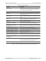
Connecting Data and Telecommunications Cables
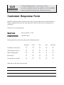
Data and telecommunication interfaces are classified according to their safety status.
The following table lists the status of several standard interfaces. If the status of a given port
differs from the standard one, a notice will be given in the manual.
Ports
Safety Status
V.11, V.28, V.35, V.36, RS-530, X.21,
10 BaseT, 100 BaseT, Unbalanced E1,
E2, E3, STM, DS-2, DS-3, S-Interface
ISDN, Analog voice E&M
SELV
xDSL (without feeding voltage),
Balanced E1, T1, Sub E1/T1
TNV-1 Telecommunication Network Voltage-1:
FXS (Foreign Exchange Subscriber)
TNV-2 Telecommunication Network Voltage-2:
Ports whose normal operating voltage exceeds the
limits of SELV (usually up to 120 VDC or telephone
ringing voltages), on which overvoltages from
telecommunication networks are not possible. These
ports are not permitted to be directly connected to
external telephone and data lines.
FXO (Foreign Exchange Office), xDSL
(with feeding voltage), U-Interface
ISDN
TNV-3 Telecommunication Network Voltage-3:
Ports whose normal operating voltage exceeds the
limits of SELV (usually up to 120 VDC or telephone
ringing voltages), on which overvoltages from
telecommunication networks are possible.
Safety Extra Low Voltage:
Ports which do not present a safety hazard. Usually
up to 30 VAC or 60 VDC.
Ports whose normal operating voltage is within the
limits of SELV, on which overvoltages from
telecommunications networks are possible.
Always connect a given port to a port of the same safety status. If in doubt, seek the assistance
of a qualified safety engineer.
Always make sure that the equipment is grounded before connecting telecommunication cables.
Do not disconnect the ground connection before disconnecting all telecommunications cables.
Some SELV and non-SELV circuits use the same connectors. Use caution when connecting cables.
Extra caution should be exercised during thunderstorms.
When using shielded or coaxial cables, verify that there is a good ground connection at both
ends. The earthing and bonding of the ground connections should comply with the local codes.
The telecommunication wiring in the building may be damaged or present a fire hazard in case of
contact between exposed external wires and the AC power lines. In order to reduce the risk,
there are restrictions on the diameter of wires in the telecom cables, between the equipment
and the mating connectors.
Caution
To reduce the risk of fire, use only No. 26 AWG or larger telecommunication line
cords.
Attention
Pour réduire les risques s’incendie, utiliser seulement des conducteurs de
télécommunications 26 AWG ou de section supérieure.
Some ports are suitable for connection to intra-building or non-exposed wiring or cabling only. In
such cases, a notice will be given in the installation instructions.
Do not attempt to tamper with any carrier-provided equipment or connection hardware.
Electromagnetic Compatibility (EMC)
The equipment is designed and approved to comply with the electromagnetic regulations of
major regulatory bodies. The following instructions may enhance the performance of the
equipment and will provide better protection against excessive emission and better immunity
against disturbances.
A good earth connection is essential. When installing the equipment in a rack, make sure to
remove all traces of paint from the mounting points. Use suitable lock-washers and torque. If an
external grounding lug is provided, connect it to the earth bus using braided wire as short as
possible.
The equipment is designed to comply with EMC requirements when connecting it with unshielded
twisted pair (UTP) cables. However, the use of shielded wires is always recommended, especially
for high-rate data. In some cases, when unshielded wires are used, ferrite cores should be
installed on certain cables. In such cases, special instructions are provided in the manual.
Disconnect all wires which are not in permanent use, such as cables used for one-time
configuration.
The compliance of the equipment with the regulations for conducted emission on the data lines
is dependent on the cable quality. The emission is tested for UTP with 80 dB longitudinal
conversion loss (LCL).
Unless otherwise specified or described in the manual, TNV-1 and TNV-3 ports provide secondary
protection against surges on the data lines. Primary protectors should be provided in the building
installation.
The equipment is designed to provide adequate protection against electro-static discharge (ESD).
However, it is good working practice to use caution when connecting cables terminated with
plastic connectors (without a grounded metal hood, such as flat cables) to sensitive data lines.
Before connecting such cables, discharge yourself by touching earth ground or wear an ESD
preventive wrist strap.
Note
The following part is applicable to non-intentional radiation only.
FCC-15 User Information
This equipment has been tested and found to comply with the limits of the Class A digital device,
pursuant to Part 15 of the FCC rules. These limits are designed to provide reasonable protection
against harmful interference when the equipment is operated in a commercial environment. This
equipment generates, uses and can radiate radio frequency energy and, if not installed and used
in accordance with the Installation and Operation manual, may cause harmful interference to the
radio communications. Operation of this equipment in a residential area is likely to cause harmful
interference in which case the user will be required to correct the interference at his own
expense.
Note
The following part is applicable to non-intentional radiation only.
Canadian Emission Requirements
This Class A digital apparatus meets all the requirements of the Canadian Interference-Causing
Equipment Regulation.
Cet appareil numérique de la classe A respecte toutes les exigences du Règlement sur le matériel
brouilleur du Canada.
Note
The following part is applicable to non-intentional radiation only.
Warning per EN 55022 (CISPR-22)
Warning
Avertissement
Achtung
This is a class A product. In a domestic environment, this product may cause radio
interference, in which case the user will be required to take adequate measures.
Cet appareil est un appareil de Classe A. Dans un environnement résidentiel, cet
appareil peut provoquer des brouillages radioélectriques. Dans ces cas, il peut être
demandé à l’utilisateur de prendre les mesures appropriées.
Dieses ist ein Gerät der Funkstörgrenzwertklasse A. In Wohnbereichen können bei
Betrieb dieses Gerätes Rundfunkströrungen auftreten, in welchen Fällen der
Benutzer für entsprechende Gegenmaßnahmen verantwortlich ist.
Regulatory Considerations for Radio Sets
In order to protect wireless telecommunication systems, local spectrum authorities may impose
restrictions on the use of radio sets. The mains regulatory regimes are those of the European
Community, which is governed by the R&TTE Directive, and USA/Canada which is governed by
USA CFR Ch. 47 and the equivalent Industry Canada regulations.
European Community
Radio-sets for use within the EU and most other European states are marked by one of the
following signs:
CE Mark. Radio-sets marked with this sign alone comply with harmonized standards and
use harmonized frequency bands. There is no limitation on their use and they do not require a
license.
CE Mark with an exclamation mark. Radio-sets marked with this mark comply with
harmonized standards but may use frequency bands which are not fully harmonized in all
member countries. Certain spectrum or telecommunications authorities may impose restrictions
on their use or require notification on the intention to operate them.
NNNN
CE Mark with an exclamation mark with a Notified Body number.
Same as above, but with the addition of a survey conducted by a Notified Body (an expert
opinion on the compliance of the radio-set with the various regulations).
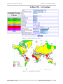
The following AirMux-200 systems comply with European regulations:
•
Airmux-200/F24E/ in the frequency range 2400-2485 MHz (RLAN). No restrictions on use.
•
Airmux-200/F54E/ in the frequency range 5470-5725 MHz (HIPERLAN). The following
restrictions (at the date of publication of this manual) are applicable:
Germany:
Frequency assignment by the Federal Network Agency is required
Italy:
General authorization required if used outside own premises
Luxemburg:
General authorization required for public service
Macedonia:
Frequency band not yet harmonized
Romania:
Frequency band not yet harmonized
Turkey:
Frequency band occupied.
The user is alerted that this list may be not complete and that in case of a doubt, the local
spectrum authorities should be consulted.
Radio-sets that use other frequency bands or with high output power, are always marked with
and their use may be restricted.
USA and Canada
Radio-sets for use in USA or Canada require certification. They are marked with an FCC Identifier
(USA) or a certificate number (Canada).
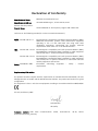
Declaration of Conformity
Manufacturer's Name:
RAD Data Communications Ltd.
Manufacturer's Address:
24 Raoul Wallenberg St., Tel Aviv 69719, Israel
declares that the product:
Product Name:
Airmux-200/F24E in the frequency range 2.400-2.4835 GHz
Conforms to the following standard(s) or other normative document(s):
Radio: EN 300 328 V1.4.1
EMC:
Electromagnetic compatibility and Radio spectrum Matters (ERM);
Wideband transmission systems; Data transmission equipment
operating in the 2.4 GHz ISM band and using wide band
modulation techniques; Harmonized EN covering essential
requirements under article 3.2 of the R&TTE Directive.
EN 301 489-1 V1.4.1 Electromagnetic compatibility and radio spectrum Matters (ERM);
ElectroMagnetic Compatibility (EMC) standard for radio equipment
and services; Part 1: Common technical requirements.
EN 301 489-4 V1.3.1 Electromagnetic compatibility and radio spectrum Matters (ERM);
ElectroMagnetic Compatibility (EMC) standard for radio equipment
and services; Part 4: Specific conditions for fixed radio links and
ancillary equipment and services.
Safety: EN 60950-1:2001
Information technology
requirements.
equipment
–
Safety
–
General
Supplementary Information:
The product herewith complies with the requirements of the EMC Directive 89/336/EEC, the Low
Voltage Directive 73/23/EEC and the R&TTE Directive 99/5/EC. The product was tested in a typical
configuration.
The equipment is Class 1 sub-class 22 equipment according to Commission Decision 2000/299/EC.
Tel Aviv, 08 February 2007
Haim Karshen
VP Quality
European Contact: RAD Data
Ottobrunn-Riemerling, Germany
Communications
GmbH,
Otto-Hahn-Str.
28-30,
85521
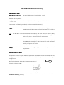
Declaration of Conformity
Manufacturer's Name:
RAD Data Communications Ltd.
Manufacturer's Address:
24 Raoul Wallenberg St. Tel Aviv 69719, Israel
declares that the product:
Product Name:
Airmux-200/F54E in the frequency range 5.470-5.725 GHz
Conforms to the following standard(s) or other normative document(s):
Radio: EN 301 893 V1.2.3
EMC:
Broadband radio Access Networks (BRAN); 5 GHz high performance
RLAN; Harmonized EN covering essential requirements of article 3.2
of the R&TTE Directive.
EN 301 489-1 V1.4.1 Electromagnetic compatibility and radio spectrum Matters (ERM);
ElectroMagnetic Compatibility (EMC) standard for radio equipment
and services; Part 1: Common technical requirements.
EN 301 489-4 V1.3.1 Electromagnetic compatibility and radio spectrum Matters (ERM);
ElectroMagnetic Compatibility (EMC) standard for radio equipment
and services; Part 4: Specific conditions for fixed radio links and
ancillary equipment and services.
Safety: EN 60950-1:2001
Information technology
requirements.
equipment
–
Safety
–
General
Supplementary Information:
The product herewith complies with the requirements of the EMC Directive 89/336/EEC, the Low
Voltage Directive 73/23/EEC and the R&TTE Directive 99/5/EC. The product was tested in a typical
configuration.
0891
Notified Body number: 0891 (TRL Compliance Services U.K)
Tel Aviv, 08 February 2007
Haim Karshen
VP Quality
European Contact: RAD Data
Ottobrunn-Riemerling, Germany
Communications
GmbH,
Otto-Hahn-Str.
28-30,
85521
Quick Start Guide
Installation of Airmux-200 should be carried out only by a qualified technician. If
you are familiar with Airmux-200, use this guide to prepare the units for
operation. If you are not familiar with Airmux-200, please read the Installation
and operation Manual carefully.
1.
Equipment Required
The following is a list of equipment required for installing an Airmux-200 link:
•
RJ-45 crimp tool (if pre-assembled cable is not used)
•
Drill (for wall mounting only)
•
IDU and ODU grounding cables
•
O-PoE 10AWG grounding cable
•
13 mm (½″) spanner/wrench
•
ODU to IDU cable if not ordered (outdoor class, CAT-5e, 4 twisted pairs)
•
ODU to O-PoE both cables (ETH and PoE) if not ordered (outdoor class,
CAT-5e, 4 twisted pairs)
•
Cable ties
•
Laptop running Windows 2000 or Windows XP.
2.
Before the Installation
1. Verify that all equipment and tools are available.
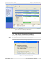
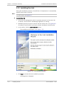
2. Install the Airmux-200 software on the laptop; the installation takes several
minutes.
The software installation leaves the Airmux-200 Manager icon on the
desktop.
3. BRS systems only - Activate the link.
Airmux-200 Ver. 1.750
Before the Installation
1
Quick Start Guide
Installation and Operation Manual
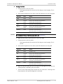
3.
Installing the Airmux-200 Units
To install the ODU:
1. At site A, route the ODU cable from the ODU location (on the roof) to the IDU
location (inside the building). The maximum length is 100m.
2. Mount the ODU unit to the mast or wall, using the mounting kit and mounting
instructions.
Note
Do not tightly secure the ODU until the alignment process is complete
When installing the ODU is important to check that there are no direct
obstructions in front of the ODU between the two link sites.
3. Verify that the ODU mounting brackets are connected to ground.
4. Connect the ODU chassis ground to ground.
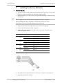
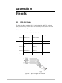
5. Connect the RJ-45 connectors to both ends of the cable using the pinout
table and diagram below:
IDU RJ-45
Wire Color
Function
ODU RJ-45
1
twisted
White/Green
Ethernet (RxN)
1
2
pair
Green
Ethernet (RxT)
2
3
twisted
White/Orange
Ethernet (TxT)
3
6
pair
Orange
Ethernet (TxN)
6
4
twisted
Blue
Power (+)
4
5
pair
White/Blue
Power (+)
5
7
twisted
White/Brown
Power (−)
7
8
pair
Brown
Power (−)
8
6. Secure the ODU and ground cables to the mast or brackets using cable ties.
7. Repeat the procedure at site B.
2
Installing the Airmux-200 Units
Airmux-200 Ver. 1.750
Installation and Operation Manual
Quick Start Guide
To align the ODU:
1. Connect power to the site A IDU.
After approximately 20 seconds the ODU beeper starts beeping. This is
normal.
2. Verify normal operation of the IDU by the LED indications on the front panel.
Caution
Indicator
Color
Status
PWR
Green
ON
IDU
Orange
Green
ON for short duration during startup
ON during normal operation
ODU
Green
ON shows normal operation
AIR I/F
Orange
Green
ON for short duration during startup
ON shows normal operation
SERVICE
Green
ON shows normal operation
OFF when Service is configured for Ethernet only
Do not stand in front of a live outdoor unit, see Appendix H .
3. Align the site A ODU in the direction of the site B ODU.
4. Connect power to the site B IDU.
After approximately 20 seconds the ODU beeper starts beeping. This is
normal.
5. Verify normal operation of the IDU by the LED indications on the panel.
Indicator
Color
Status
PWR
Green
ON IDU-E only
IDU
Orange
Green
ON for short duration during startup
ON during normal operation
ODU
Green
ON shows normal operation
AIR I/F
Orange
Green
ON for short duration during startup
ON shows normal operation
SERVICE
Green
ON shows normal operation
OFF when Service is configured for Ethernet only
6. Make an azimuth sweep with the site B ODU of 180 degrees so that the site
A ODU position is learned by the site B ODU.
7. Turn the site B ODU slowly back towards the site A direction, listening to the
beep sequence until optimal alignment is achieved.
Airmux-200 Ver. 1.750
Installing the Airmux-200 Units
3
Quick Start Guide
Note
Installation and Operation Manual
Three beeps and a pause is the best signal
Two beeps and a pause, signal quality increased
One beep and pause is no signal change
Any other signal detects no signal between ODUs.
8. Secure the site B ODU to the mast/wall.
9. At site A, adjust the ODU slowly while listening to the beeper sequence until
the best signal is attained.
10. Secure the site A ODU to the mast/wall.
11. Monitor the link quality for about 15 minutes to verify stability.
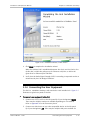
12. Connect the management station to one of the two IDUs in the link.
13. Double-click the Airmux-200 Manager icon to start the application.
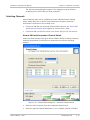
14. Click the Installation button to open the installation wizard and follow the
installation steps.
After selection of the radio channel and the link rate (as determined in the Link
Budget Calculator utility), verify that the link quality bar in the Airmux-200
manager is within the green range for TDM service and within the yellow range
for Ethernet service.
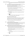
Note
Achieve the best possible link quality values. In case of radio link loss, verify the
ODU alignment, or change the radio channel in both sides of the link. When the
radio link resumes, continue the installation process.
To install the Outdoor PoE (O-PoE):
1. Route the ODU cable from the ODU location (on the roof) to the O-PoE
location (also on the roof). The maximum combined length of the ODU to
Outdoor PoE cable and the O-PoE to user hub/router (or any other
compatible device) cable is 100m.
2. Mount the O-PoE unit to the mast or wall, using the mounting kit and
mounting instructions.
3. Verify that the O-PoE mounting brackets are connected to ground.
4. Connect the O-PoE chassis to ground.
5. Route the O-PoE AC cable along the mast or wall to a protected/shielded AC
outlet.
4
Installing the Airmux-200 Units
Airmux-200 Ver. 1.750
Installation and Operation Manual
Quick Start Guide
Only UL Listed parts and components will be used for installation. Use UL Listed
devices having an environmental rating equal to or better than the enclosure
rating to close all unfilled openings
Warning
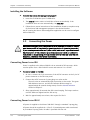
4.
Connecting the Power
Before connecting any cable, the protective earth terminals of the AC/DC adapter
must be connected to the protective ground conductor of the mains power cord.
If you are using an extension cord (power cable) make sure it is grounded as well.
Warning
Any interruption of the protective (grounding) conductor (inside or outside the
instrument) or disconnecting of the protective earth terminal can make this unit
dangerous. Intentional interruption is prohibited.
Connecting Power to an IDU
Power is supplied to the Airmux-200 via an external AC/DC converter, which
receives power from 100–240 VAC source and converts it to -48 VDC.
To connect power to the IDU:
1. At site A, connect the 2-pin connector of the AC/DC converter to the 2-pin DC
power connector on the IDU rear panel.
2. Connect the AC/DC converter 3-prong plug to a mains outlet.
The unit turns on automatically upon connection to the mains.
The green PWR indicator turns on, and the IDU indicator blinks orange for
approximately 40 seconds during startup. See Normal Indicators section
in Chapter 3.
3. After approximately 20 seconds the ODU starts beeping. The beeps continue
until the ODUs are aligned and the link set up.
4. Wait for approximately one minute, then repeat for Site B.
Connecting Power to an IDU-E
AC power to the Airmux-200 should be supplied via a 1.5m (5 ft) standard power
cable terminated by a standard 3-prong socket. A cable is provided with the unit.
To connect AC power to an IDU-E:
1. Connect the power cable socket to the power connector on the Airmux-200
front panel.
2. Connect the power cable plug to the mains outlet.
The unit will be turned on automatically upon connection to the mains.
To connect DC power to an IDU-E
A special IEC 60320 adapter for -48 VDC or -24 VDC power connection is supplied
with the unit.
Airmux-200 Ver. 1.750
Connecting the Power
5
Quick Start Guide
Installation and Operation Manual
Connecting Power to an O-PoE
AC power is supplied to the O-PoE via a 3m (10 ft) 3-prong AC cable attached to
the unit (pigtail). The AC cable is provided with no termination.
To connect AC power to an O-PoE:
Connect the power cable to a protected/shielded AC mains outlet.
The unit will be turned on automatically upon connection to the mains.
Warning
To maintain Overvoltage (Installation) Category II, install a suitable surge
suppressor device in the branch circuit to limit expected transients to Overvoltage
Category II values.
The limits are based on IEC60664 and are also located in Table 2H of UL60950.
For mains of 150V, the transient rating is 1500V. For mains between 150V and
300V, the transient rating is 2500V. For mains between 300V and 600V, the
transient rating is 4000V.
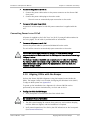
5.
Connecting the User Equipment
To connect user equipment to the IDU:
1. Connect the user equipment (such as PBX) to the IDU RJ-45 port designated
Trunk:
On the rear panel of the IDU
On the front panel of the IDU-E
2. Connect user hub/router or any other compatible device to the IDU RJ-45 port
designated LAN.
On the rear panel of the IDU
On the front panel of the IDU-E
To connect user equipment to the O-PoE:
1. Connect user hub/router or any other compatible device to the port
designated ETH via an outdoor shielded CAT-5e cable. To connect directly to
PC LAN port, refer to Appendix A.
• IDU-E has an integrated LAN switch that provides two 10/100BaseT ports. The
Note
Integrated LAN switch does not support spanning tree.
• The two LAN ports can be connected to two separate LAN segments.
6
Connecting the User Equipment
Airmux-200 Ver. 1.750
Installation and Operation Manual
Caution
Caution
Quick Start Guide
Do not connect both LAN ports to the same LAN segment, a loop will be created
that will flood the network.
For O-PoE only UL Listed parts and components are used for installation. Use UL
listed devices having an environmental rating equal to or better than the
enclosure rating to close all unfilled openings.
Airmux-200 Ver. 1.750
Connecting the User Equipment
7
Quick Start Guide
8
Connecting the User Equipment
Installation and Operation Manual
Airmux-200 Ver. 1.750
Contents
Chapter 1. Introduction
1.1
1.2
1.3
1.4
Overview....................................................................................................................1-1
Application .............................................................................................................1-1
Product Options......................................................................................................1-1
Features .................................................................................................................1-2
Wireless Link ......................................................................................................1-2
LAN Interface .....................................................................................................1-2
TDM Interface ....................................................................................................1-2
Advanced Encryption System..............................................................................1-2
Management......................................................................................................1-3
Diagnostics and Performance Monitoring............................................................1-3
Automatic Channel Select ...................................................................................1-3
Adaptive Modulation ..........................................................................................1-3
Transmit Power Control ......................................................................................1-3
Alarm Connector ................................................................................................1-3
Link Compatibility...............................................................................................1-4
Optional External Antenna..................................................................................1-4
Hub Site Synchronization ...................................................................................1-4
E1 Trunk Redundancy.........................................................................................1-4
VLAN Management .............................................................................................1-4
Physical Description ...................................................................................................1-5
IDU .........................................................................................................................1-5
IDU-E......................................................................................................................1-6
ODU .......................................................................................................................1-6
PoE-8 .....................................................................................................................1-6
O-PoE.....................................................................................................................1-7
Functional Description................................................................................................1-7
Technical Specifications..............................................................................................1-8
Chapter 2. Installation and Setup
2.1
2.2
2.3
2.4
2.5
2.6
2.7
2.8
2.9
2.10
2.11
2.12
2.13
Introduction...............................................................................................................2-1
Site Requirements and Prerequisites ..........................................................................2-1
Package Contents ......................................................................................................2-2
Additional Equipment Required...................................................................................2-3
Installation Sequence .................................................................................................2-3
Mounting the ODU or O-PoE.......................................................................................2-4
Connecting the ODU or O-PoE to the IDU ...................................................................2-5
Airmux-200 Management Software ............................................................................2-7
Minimum Requirements ..........................................................................................2-7
Installing the Software............................................................................................2-8
Connecting the Power ................................................................................................2-8
Connecting Power to an IDU ...................................................................................2-8
Connecting Power to an IDU-E ................................................................................2-8
Connecting Power to an O-PoE ...............................................................................2-9
Aligning ODUs with the Beeper...................................................................................2-9
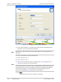
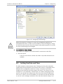
Starting the Airmux-200 Manager Software ..............................................................2-10
Over-the-Air Connection Indication...........................................................................2-13
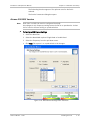
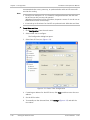
Installing the Link.....................................................................................................2-14
Selecting Channels................................................................................................2-17
Airmux-200 Ver. 1.750
i
Table of Contents
Installation and Operation Manual
Airmux-200 with Automatic Channel Select.......................................................2-17
Airmux-200 5.4 GHz ETSI Version......................................................................2-18
Airmux-200 BRS Version........................................................................................2-19
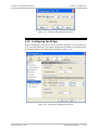
Selecting the Service Parameters ..........................................................................2-20
Setting the Clock Configuration .............................................................................2-21
Setting the T1 Line Code.......................................................................................2-23
Setting the TDM Backup........................................................................................2-23
2.14 Connecting the User Equipment ...............................................................................2-25
Chapter 3. Operation
3.1
3.2
3.3
3.4
3.5
Turning On Airmux-200 ..............................................................................................3-1
Controls and Indicators ..............................................................................................3-1
IDU Front Panel Indicators.......................................................................................3-1
WAN/LAN Indicators................................................................................................3-3
Normal Indications..................................................................................................3-3
Default Settings .........................................................................................................3-4
Managing Airmux-200 ................................................................................................3-4
Turning Off Airmux-200..............................................................................................3-7
Chapter 4. Configuration
4.1
4.2
4.3
4.4
4.5
4.6
4.7
4.8
4.9
4.10
4.11
4.12
4.13
4.14
4.15
4.16
4.17
4.18
ii
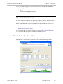
Configuring the System Parameters............................................................................4-1
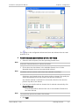
Selecting Channels .....................................................................................................4-3
Airmux-200 with Automatic Channel Select .............................................................4-3
Airmux-200 5.4 GHz ETSI Version ............................................................................4-4
Airmux-200 BRS Version..........................................................................................4-6
Configuring Service Parameters ..................................................................................4-7
Configuring TDM Operation ........................................................................................4-8
Setting the Clock Configuration ...............................................................................4-8
Setting the T1 Line Code.......................................................................................4-10
Setting the TDM Backup (IDU-R only) ....................................................................4-11
Editing the Configuration Parameters .......................................................................4-12
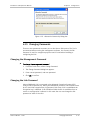
Changing the Transmit Power...................................................................................4-13
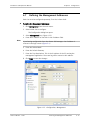
Defining the Management Addresses .......................................................................4-15
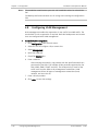
Configuring VLAN Management ................................................................................4-16
Setting the Date and Time .......................................................................................4-17
Configuring the Bridge .............................................................................................4-19
ODU Bridge Mode .................................................................................................4-20
IDU Aging time......................................................................................................4-20
Configuring Ethernet Mode.......................................................................................4-20
Setting the Maximum Information Rate ....................................................................4-21
Configuring the Jitter Buffer .....................................................................................4-22
Changing Community Values.....................................................................................4-23
Editing Community Strings ....................................................................................4-23
Forgotten Community String .................................................................................4-24
Changing Passwords ................................................................................................4-25
Changing the Management Password ....................................................................4-25
Changing the Link Password..................................................................................4-25
Forgotten the Link Password.................................................................................4-26
Muting the Beeper ...................................................................................................4-26
Setting External Alarm Inputs ...................................................................................4-27
Managing Configuration Files....................................................................................4-28
Saving the Airmux-200 Configuration in a File........................................................4-28
Airmux-200 Ver. 1.750
Installation and Operation Manual
4.19
4.20
4.21
4.22
Table of Contents
Restoring a Configuration File ...............................................................................4-28
Reinstalling the Link .................................................................................................4-28
Resetting Airmux-200 ..............................................................................................4-29
Displaying the Inventory...........................................................................................4-29
Configuration via Telnet ...........................................................................................4-30
Chapter 5. Diagnostics and Troubleshooting
5.1
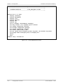
5.2
Automatic Link Data Collection (Get Link Information) ................................................5-1
Monitoring Performance.............................................................................................5-2
Saving the Monitor Log ...........................................................................................5-2
Setting the Events Preferences ...............................................................................5-3
Saving the Events Log .............................................................................................5-4
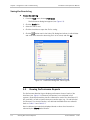
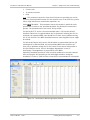
5.3 Viewing Performance Reports.....................................................................................5-4
5.4 Error Detection and Alarms ........................................................................................5-7
5.5 Remote Power Fail Indication .....................................................................................5-9
5.6 Link Compatibility.....................................................................................................5-10
5.7 Testing Airmux-200..................................................................................................5-11
Local External Loopback ........................................................................................5-12
Remote Internal Loopback ....................................................................................5-12
Remote External Loopback....................................................................................5-13
Local Internal Loopback ........................................................................................5-13
5.8 Troubleshooting.......................................................................................................5-14
5.9 Replacing an ODU ....................................................................................................5-15
5.10 Frequently Asked Questions .....................................................................................5-15
5.11 Technical Support ....................................................................................................5-18
Appendix A. Pinouts
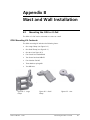
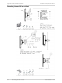
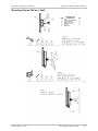
Appendix B. Mast and Wall Installation
Appendix C. Link Budget Calculator
Appendix D. AIND Antenna Alignment Procedure
Appendix E. Antenna Characteristics
Appendix F. Hub Site Synchronization
Appendix G. BRS Installation Procedure
Airmux-200 Ver. 1.750
iii
Table of Contents
iv
Installation and Operation Manual
Airmux-200 Ver. 1.750
Chapter 1
Introduction
1.1
Overview
Airmux-200 is a carrier-class, high capacity, point-to-point broadband wireless
transmission system. Airmux-200 combines legacy TDM and Ethernet services
over 2.3 to 2.7 and 4.0 to 5.9 GHz bands, and is suitable for deployment in FCC,
ETSI, CSA-regulated countries, and other regions. The system provides up to
48 Mbps wireless link and supports ranges of up to 80 km (50 miles) with an
external antenna.
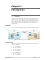
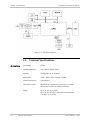
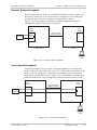
Application
Figure 1-1 illustrates a typical point-to-point application of two Airmux-200 units.
Figure 1-1. Typical Point-to-Point Application
Product Options
Airmux-200 is available in several different frequency ranges, with versions for
ETSI and FCC regulations;
•
F23, 2.300–2.400 GHz
•
F24, 2.400–2.4835 GHz
•
F25, 2.496–2.690 GHz
•
F49, 4.940–4.990 GHz
•
F53, 5.250–5.350 GHz
•
F54, 5.470–5.725 GHz
•
F58, 5.725–5.850 GHz
Airmux-200 Ver. 1.750
Overview
1-1
Chapter 1 Introduction
•
Installation and Operation Manual
F59, 5.865–5.935 GHz
Several special systems are also available;
•
AIRMUX-200-AIND, All Indoor unit, F58/FCC with 4T1 support.
AIRMUX-200-AIND integrates the ODU and the IDU-E into a single 19" IDU-E
box.
•
AIRMUX-200-L, Ethernet only units powered over the Ethernet via PoE unit.
Available in F23, F24, or F58 frequency ranges.
•
AIRMUX-200-LC, ODU is equipped with special hardware for the collocation of
several units, using Hub Site Synchronization (HSS).
Features
Wireless Link
Airmux-200 delivers up to 48 Mbps air rate for Ethernet and E1/T1 traffic. The
system supports a variety of spectrum bands and can be configured to operate in
any channel in the band with a carrier step resolution of 5, 10, or 20 MHz.
Airmux-200 operation complies with ETSI, CSA, CN, UK, and the FCC 47CFR Part
15 and subpart C and E requirements.
Airmux-200 employs Time Division Duplex (TDD) transmission. This technology
simplifies the installation and configuration procedure. There is no need to plan
and to allocate separate channels for the uplink and downlink data streams.
Operation over 2.4 GHz and 5.x GHz bands is not affected by harsh weather
conditions, such as fog and heavy rain.
LAN Interface
The Airmux-200 LAN port provides 10/100BaseT interfaces with autonegotiation
and transparent VLAN support. Traffic handling is provided by a MAC-level
self-learning bridge.
TDM Interface
The Airmux-200 TDM interface accepts E1 or T1 traffic, supporting the following:
•
Unframed operation (E1 and T1)
•
AMI and B8ZS zero suppression (T1).
Advanced Encryption System
Airmux-200 (version 1.500 and above) ensures user's data security with one of
the most sophisticated commercially available combined encryption and
authentication techniques, CCM/AES. This technique combines message
authentication (preventing antispoofing and replay protection) with commercial
encryption, and complies with the IEEE 802.11i (phase iii) security
recommendations.
CCM/AES uses a symmetric 128-bit encryption key (EK), and a nonce, and
provides both message encryption and authenticating signature. The nonce
mechanism enables the receiver to remember already received genuine messages
and reject all replayed messages.
1-2
Overview
Airmux-200 Ver. 1.750
Installation and Operation Manual
Chapter 1 Introduction
Initial encryption and authentication is based on a user-defined master key (Link
Password). While standard wireless LAN encrypts only the Ethernet payload,
Airmux-200 encrypts both the source and destination MAC addresses.
Management
Airmux-200 has full local and remote management capabilities. The user-friendly
SNMP-based management tool provides full end-to-end configuration, event log
and performance monitoring capabilities.
Alternatively each site can be configured or monitored via a Telnet terminal.
Diagnostics and Performance Monitoring
Airmux-200 supports activating local and remote loopbacks on E1/T1 links.
Airmux-200 constantly monitors the data transmission process, evaluates
received signal strength, and signal quality. It also monitors received traffic and
frame rate (FPS) for local and remote units.
Automatic Channel Select
Some versions of Airmux-200 have the Automatic Channel Select feature, which
operates via a Dynamic Frequency Selection (DFS) mechanism. This enables
coexistence with any radar system that may be active in the area. Airmux-200
performs channel monitoring and selects the channel with the lowest
interference for the transmission. Airmux-200 operation complies with ETSI
requirements where the ETSI version has been purchased.
Adaptive Modulation
Airmux-200 changes modulation automatically depending on channel
characteristics in order to guarantee continuation of service. The adaptive
modulation enables the user to maximize Ethernet throughput without
degradation of the TDM service quality. When Ethernet only service is used, the
adaptive modulation enables improving the Ethernet performance in case of air
performance degradation (periodical interference or RSS changes).
In case of interference at one site, there is no need to use a lower modulation at
the other site (as in previous versions). In such a case the actual rate changes
automatically only at the problematic site, while the second side of the link
maintains the highest possible rate (Asymmetric).
Adaptive modulation can be selected in both installation and configuration
wizards.
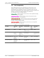
Transmit Power Control
The Transmit Power Control (TPC) function, provides the capability of defining the
transmit power in order to comply with the ETSI standard requirement of 30 dB
maximum. See Table 4-1 for full details of transmit power control.
Alarm Connector
The IDU-E has eight external alarm inputs and outputs in the form of dry-contact
relays. The Alarm interface is located on the front panel of the IDU-E. The user
enables or disables each of the alarms and configures the text that appears in
Airmux-200 Ver. 1.750
Overview
1-3
Chapter 1 Introduction
Installation and Operation Manual
the alarm trap. The ODU sends the alarm within less than a second from actual
alarm trigger.
The alarm connector is available as an ordering option for the IDU.
Link Compatibility
Airmux-200 indicates the version compatibility via software traps. As new
hardware is added to existing networks compatibility issues may arise. Trap
messages indicate the problem and suggest upgrades as appropriate.
Optional External Antenna
Airmux-200 supports configuration of an external antenna. In this configuration,
the outdoor unit is supplied with an N-type connector that connects through a
coax cable to the external antenna.
An external antenna can extend the range of the link, and in some cases, may
help to reduce environmental interferences. Various external antennas are
available for the Airmux-200 operating frequencies.
For example, an optional flat panel 28 dBi external antenna increases the
operation range of Airmux-200 up to 80 km (50 miles).
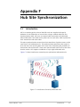
Hub Site Synchronization
When several Airmux-200 units are collocated at a common hub site interference
may occur from one unit to another. Airmux-200 ODU units are supplied with
special hardware for the collocation of up to eight units.
Using a method called Hub Site Synchronization (HSS) an external cable is
connected to all collocated Airmux-200 ODUs, this cable carries pulses sent to
each ODU, which synchronize their transmission with each other. (See Appendix F
for more details).
E1 Trunk Redundancy
IDU-R units have a secondary E1 input which may be connected to external
equipment other than the ODU. This provides backup in the event of failure of
either the air interface link of the Airmux-200, or the secondary E1 link.
The user configures which of the two links is the main link and which is the
backup link.
VLAN Management
VLAN management allows the separation of user traffic from NMS traffic. The
user decides if such a separation is required. Both the headquarters and remote
sites are configured with VLAN management.
1-4
Overview
Airmux-200 Ver. 1.750
Installation and Operation Manual
1.2
Chapter 1 Introduction
Physical Description
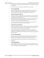
An Airmux-200 system may consist of an Outdoor Unit (ODU) and an Indoor Unit,
which may be an IDU or an IDU-E; an All Indoor Unit, AIND; or an all outdoor unit
O-PoE, housed in a weather proof enclosure.
Figure 1-2 shows the IDU, IDU-E carrier class unit, and an ODU with integrated
antenna.
Figure 1-2. Airmux-200 Units
Figure 1-3. Airmux-200 O-PoE Unit
IDU
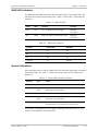
The front panel of the IDU includes five LEDs, which display the status of E1/T1
traffic, wireless link, self-test results, the ODU-to-IDU link, and power status. For
a detailed description of the front panel LEDs, see Chapter 3.
The rear panel of the IDU includes the connectors for power, WAN, LAN, E1/T1,
and the ODU. The wiring specifications are detailed in Appendix A. The rear panel
LEDs are described in Chapter 3.
Airmux-200 Ver. 1.750
Physical Description
1-5
Chapter 1 Introduction
Installation and Operation Manual
IDU-E
The IDU-E front panel includes four LEDs that display the status of E1/T1and,
wireless link, self-test results, and ODU-to-IDU link. For a detailed description of
the front panel LEDs, see Chapter 3.
ODU
ODU includes a power connector, which receives -48 VDC, and RJ-45 for Ethernet
traffic from the IDU. The ODU is attached to a mast using a special mounting kit,
which is supplied with the unit.
The ODU can be used with an integrated antenna, as illustrated in Figure 1-2, or
with an external antenna. If an external antenna is to be used, then the ODU is
supplied fitted with an N-type connector.
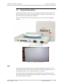
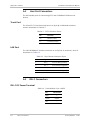
PoE-8
Airmux-200 PoE-8 is an IDU for collocated Ethernet applications. It features 8
Ethernet ports, 8 decoupled ports of ODU, 2 outputs of dry contact alarms, and
receives power by AC, DC, or both as either AC input or DC input – 20V - 60V.
Figure 1-3. Airmux-200 PoE-8
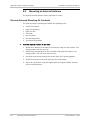
Table 1-1. PoE-8 Features
Features
Description
Number of ports
8 Ethernet ports
8 decoupled ODU ports
LEDs
Input power – red/green bicolor
Green – Input power is within range
Red – Input power is out of range
LEDs per each ODU port [RJ45]
Green – The ODU is connected and is normally operating
Red – Over-current (shorted)
When the red LED is On the green LED must be Off.
Alarms
2 Dry contact alarm outputs
Dry contact #1: A red ODU port LED is on.
Dry contact #2: The input power red LED is on (out of range).
1-6
Physical Description
Airmux-200 Ver. 1.750
Installation and Operation Manual
Chapter 1 Introduction
Features
Description
Power Source
100–240 VAC
20 to 60 VDC (protected against reverse polarity connection)
AC/DC or both
O-PoE
O-PoE (Outdoor Power over Ethernet) includes an AC power cable with no
termination which can be connected to100-220 VAC outlet. The designated PoE
connector is connected to an ODU via a shielded CAT-5e twisted pair cable and
delivers Ethernet traffic with 48 VDC power towards the ODU. The designated
ETH connector is connected via a shielded CAT-5e twisted pair cable which
receives and delivers Ethernet traffic. The wiring specification for the twisted pair
cable is detailed in Appendix A
The O-PoE is attached to a mast using a special mounting kit, which is supplied
with the unit.
Note
To connect the ETH port from O-PoE to a PC, a crossed LAN cable must me used.
See Appendix A.
1.3
Functional Description
Airmux-200 system comprises of the following units:
•
•
•
Airmux-200 Ver. 1.750
Outdoor Unit (ODU): An enclosed aluminum frame with a front sealed plastic
cover, containing an integrated transceiver with an antenna, RF module,
modem and standard interfaces. The ODU stores all the configuration
parameters of the Airmux-200 system. Figure 1-4 shows the ODU block
diagram.
Indoor Unit (IDU or IDU-E): The interface unit between the ODU and the user.
It converts 100–240 VAC to -48 VDC, and sends it on to the ODU. The IDU
does not store any configuration data. Therefore, there is no need for
additional configuration of the Airmux-200 system when replacing an IDU.
Outdoor PoE (O-PoE): An enclosed aluminum frame with a front sealed
aluminum cover, containing a 110-220 VAC to 48 VDC switching power supply
and an interface interconnecting an un-powered Ethernet infrastructure to
ODU.
Functional Description
1-7
Chapter 1 Introduction
Installation and Operation Manual
Figure 1-4. ODU Block Diagram
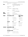
1.4
Air Interface
1-8
Technical Specifications
Technology
OFDM
Duplexing Method
Time Division Duplex (TDD)
Capacity
Configurable up to 48 Mbps
Modulation
OFDM - BPSK, QPSK, 16QAM, 64QAM
Channel Resolution
5/10/20 MHz
Transmitter Power
Specification is different per product, for further
details refer to the Link Budget Calculator
Range
Up to 41 km (25.5 miles)
Up to 80 km (50 miles) with an external antenna
L versions up to 20 km
Technical Specifications
Airmux-200 Ver. 1.750
Installation and Operation Manual
Frequency Bands
[GHz]
and Standards
Chapter 1 Introduction
2.300–2.483
FCC, ETSI
2.496–2.690
FCC part 27 (BRS)
4.940–4.990
FCC
5.150–5.350
FCC
5.470–5.725
ETSI
5.725–5.850
FCC
Antennas
(See Antenna Characteristics in Appendix E)
LAN Interface
PHY
Up to 2 × 10/100BaseT, auto-sensing
Framing/Coding
IEEE 802.3/U
Bridging
Self-learning, up to 2048 MAC addresses
Line Impedance
100Ω
VLAN Support
Transparent
Frame Size
1536 bytes max
Connector
RJ-45
Data Rate
Unframed (transparent) 2.048 MHz
(Specification may be different per ordering option)
Line Interface
HDB3
Connector
RJ-45
No. of Ports
IDU: 1 or 2
IDU-E: 4
Data Rate
Unframed (transparent) 1.544 MHz
(Specification may be different per ordering option)
Zero Suppression
AMI, B8ZS
Connector
RJ-45
No. Of Ports
IDU: 1 or 2
IDU-E: 4
PWR (green)
Power status (IDU only)
IDU (green)
IDU-E status
ODU (green/red)
ODU-to-IDU link status
LINK (green/red)
Link status
E1 Interface
T1 Interface
Indicators
Airmux-200 Ver. 1.750
Technical Specifications
1-9
Chapter 1 Introduction
Power
Alarm
Connector
Physical
Installation and Operation Manual
SERVICE (green/red)
E1/T1 signal status
Source
IDU: 100–240 VAC via external AC/DC converter
IDU-E: 100–240 VAC via AC cable
-48 VDC (-42 to –60 VDC), 24 VDC
Power Received by
the ODU
-48 VDC
Power Consumption
ODU plus IDU – 10W max
ODU plus IDU-E – 14W max
Connector
IDU 2-pin
IDU-E AC – 3-pin IEC connector
DC – 3-pin terminal block
Connector
DB-9 female
Electrical
Characteristics
Dry Contact, 30V/2A
Max input current, 0.01A at 0.5W (R=5K)
Outdoor Unit (ODU and O-PoE)
Environment
ODU with integrated
antenna
Height
24.5 cm (9.3 in)
30.5 cm (12 in)
Width
13.5 cm (5.13 in)
30.5 cm (12 in)
Depth
4.0 cm (1.57 in)
5.8 cm (2.3 in)
Weight
1.0 kg (2.2 lb)
1.5 kg (3.3 lb)
Indoor Unit
IDU
IDU-E
Height
4.5 cm (1.7 in) 1U
4.5 cm (1.7 in) 1U
Width
23.5 cm (9.3 in)
29 cm (11.5 in)
Depth
16.5 cm (6.7 in)
43 cm (17.7 in)
Weight
0.5 kg (1.1 lb)
1.5 kg (3.3 lb)
Outdoor Unit (ODU and O-PoE)
Enclosure
All-weather case
Temperature
-35° to 60°C (-31° to 140°F)
Indoor Unit (IDU and IDU-E)
1-10
Temperature
-0° to 50°C (32° to 122°F)
Humidity
Up to 90%, non-condensing
Technical Specifications
Airmux-200 Ver. 1.750
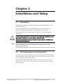
Chapter 2
Installation and Setup
2.1
Introduction
This section describes the installation, alignment, and setup procedures for an
Airmux-200 system.
After installing the hardware and establishing a link, refer to Chapter 3 for
operation instructions and Chapter 4 for configuration instructions.
In case a problem is encountered, refer to Chapter 5 for test and diagnostic
instructions.
Internal settings, adjustment, maintenance, and repairs may be performed only
by a skilled technician who is aware of the hazards involved.
Warning
Note
Always observe standard safety precautions during installation, operation, and
maintenance of this product.
Before installing the product, review Handling Energized Products at the
beginning of the manual.
2.2
Site Requirements and Prerequisites
For the IDU units, allow at least 90 cm (36 in) of frontal clearance for operating
and maintenance -Libility. Allow at least 10 cm (4 in) clearance at the rear of the
unit for signal lines and interface cables.
The ambient operating temperature should be –45° to 60°C (–49° to 140°F)
(ODU), or –5° to 45°C (23° to 113°F) (IDU) at a relative humidity of up to 90%,
non-condensing.
Airmux-200 Ver. 1.750
Site Requirements and Prerequisites
2-1
Chapter 2 Installation and Setup
2.3
Installation and Operation Manual
Package Contents
The Airmux-200 packages include the following items:
ODU package containing:
ODU
Mast/Wall mounting kit plus mounting instructions
CD-ROM [Airmux-200 Manager, Installation and Operation Manual, and
Link Budget Calculator]
Self adhesive label showing the MAC address and the alternative
community string KEY. Keep this label safe.
Spare RJ-45 connector
IDU or IDU-R package containing:
IDU or IDU-R
AC/DC Converter
IDU wall-mounting drilling template
Self adhesive label showing the IDU LED operation
Spare RJ-45 connector
Or
IDU-E Package Containing:
IDU-E
For AC model, 110/240 VAC with 3-prong connector cable
For DC model, 3-pin terminal block connector (green)
19” mounting kit
Spare RJ-45 connector
External antenna (if ordered)
1m connecting cable
Mounting kit
ODU/IDU cable at length ordered (optional)
O-PoE package contains:
O-PoE
Mast/Wall mounting kit plus mounting instructions
Spare RJ-45 connector
2-2
Package Contents
Airmux-200 Ver. 1.750
Installation and Operation Manual
2.4
Chapter 2 Installation and Setup
Additional Equipment Required
The following is a list of the equipment required for installing the Airmux-200
hardware:
•
RJ-45 crimp tool (if pre-assembled ODU/IDU cable is not used)
•
Drill (for wall mounting only)
•
IDU and ODU grounding cables
•
O-PoE 10AWG grounding cable
•
13 mm (½″) spanner/wrench
•
Cable ties
•
Laptop running Windows 2000 or Windows XP.
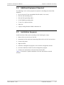
2.5
Installation Sequence
Install the Airmux-200 system according to the following the steps:
1. Mount ODUs at both sites of the link.
2. Assemble the ODU cable and connecting ODU to IDU or O-PoE at both sites.
3. Connect the power.
4. Align the ODUs.
5. Install the management program on the network management station.
6. Run the installation wizard from the management program.
7. Connect user equipment to the local and remote IDUs.
Figure 2-1 illustrates a typical installation of Airmux-200 with an external
antenna.
Airmux-200 Ver. 1.750
Installation Sequence
2-3
Chapter 2 Installation and Setup
Installation and Operation Manual
Figure 2-1. Typical Installation Diagram
2.6
Mounting the ODU or O-PoE
The ODU is the transmitting and receiving element of the Airmux-200 system. The
ODU or O-PoE can be mounted on a mast or a wall. In both installations, the
supplied mounting kit is used to secure the ODU. Appendix B describes the
mast/wall installation instructions.
An Airmux-200 link operates in pairs of two ODUs with the same configuration.
Both ODUs must be installed, and the antennas aligned for maximum throughput.
2-4
Mounting the ODU or O-PoE
Airmux-200 Ver. 1.750
Installation and Operation Manual
Warning
Chapter 2 Installation and Setup
Prior to connecting cables to the ODU, the protective earth terminal (screw) of
the ODU must be connected to an external protective ground conductor or to a
grounded mast. For an O-PoE the grounding cable must be connected to an
external protective ground conductor or to a grounded mast via the mounting ear
of the O-PoE.
Only a qualified person using the proper safety equipment should climb the
antenna mast. Only trained professional installers should be used when installing
or dismantling ODUs and masts.
To mount the ODU or O-PoE:
1. Verify that the ODU or O-PoE mounting brackets are properly grounded.
2. Mount the ODU unit onto the mast or wall. For ODU mounting instructions,
refer to Appendix B.
3. Connect the ground cable to the chassis point on the ODU.
4. Attach the ODU-IDU cable to the ODU RJ-45 connector. If making your own
ODU-IDU cable, refer to Appendix A for the connector pinout.
5. Secure the cable to the mast or brackets using UV-rated cable ties.
6. Repeat the procedure at the remote site.
Note
Do not tightly secure the ODU to its mounting brackets until the alignment
process of the antenna is complete.
When installing the ODU, check that there are no direct obstructions in front of
the ODU or interference from man-made obstacles.
Caution For O-PoE, UL listed parts and components must be used for installation. Use UL
listed devices having an environmental rating equal to or better than the
enclosure rating to close all unfilled openings.
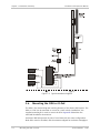
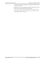
2.7
Connecting the ODU or O-PoE to the IDU
The ODU-IDU cable conducts all the user traffic between the IDU and the ODU or
O-PoE. The ODU-IDU cable also provides -48 VDC supply and Ethernet to the
ODU. The maximum length for one leg of the ODU-IDU cable is 100m (328 ft) in
accordance with 10/100BaseT standards. When using an O-PoE, the maximum
length for two legs of the O-PoE cable is 100m (328 ft) in accordance with
10/100BaseT standards.
The ODU-IDU cable is supplied with pre-assembled with RJ-45 connectors, at the
length specified when ordering. If the ODU-IDU cable was not ordered, use Cat.
5e shielded cable. Wiring specifications are given in Appendix A.
Airmux-200 Ver. 1.750
Connecting the ODU or O-PoE to the IDU
2-5
Chapter 2 Installation and Setup
Installation and Operation Manual
To connect the ODU or O-PoE to the IDU
1. ODU: Route the cable from the ODU to the IDU.
O-PoE: Route the cable from ODU to O-PoE along the mast or wall.
2. Secure the cable along its path.
3. ODU: Connect the ODU-IDU cable to the RJ-45 connector on the IDU
designated ODU or WAN.
O-PoE: Connect the ODU-IDU cable to the RJ-45 connector on the O-PoE
designated PoE.
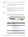
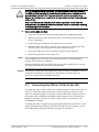
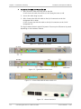
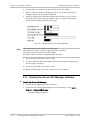
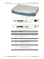
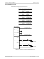
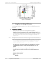
The figures below illustrate typical IDU panels. There may be differences in panels
depending on the hardware ordered.
DC IN
48-60V --- 1A
- +
ODU
LAN
TRUNK 1
TRUNK 2
Figure 2-2. Typical IDU Rear Panel
Figure 2-3. Typical IDU-E Front Panels
Figure 2-4. Airmux-200-AIND All Indoor Radio Unit
Figure 2-5. Airmux-200 PoE-8
2-6
Connecting the ODU or O-PoE to the IDU
Airmux-200 Ver. 1.750
Installation and Operation Manual
Chapter 2 Installation and Setup
Figure 2-6. Airmux-200 Outdoor PoE (O-PoE)
Note
Panels may be fitted with different connector combinations than shown,
depending on the model ordered.
2.8
Airmux-200 Management Software
Minimum Requirements
The Airmux-200 management application is distributed on CD-ROM as an
executable file. The application has the following PC requirements:
•
Memory: 128 MB RAM
•
Disk: 1 GB free hard disk space
•
Processor: Pentium 3 or higher
•
Network: 10/100BaseT NIC
•
Graphics: Card and monitor that support 1024×768 screen resolution
with 16 bit color
•
Operating system: Windows 2000/XP
•
Microsoft Explorer 5.01 or later.
Airmux-200 Ver. 1.750
Airmux-200 Management Software
2-7
Chapter 2 Installation and Setup
Installation and Operation Manual
Installing the Software
To install the Airmux-200 management program:
1. Insert the CD-ROM into your CD-ROM drive.
2. The autorun feature starts to install the software automatically. If the
installation does not start automatically, run setup.exe.
3. Follow the on-screen instructions of the installation wizard to complete setup
of the Airmux-200 management program in the desired location.
Any PC running the Airmux-200 management application can be used to configure
Airmux-200 units.
2.9
Connecting the Power
Before connecting any cable, the protective earth terminals of the AC/DC adapter
must be connected to the protective ground conductor of the mains power cord.
If you are using an extension cord (power cable) make sure it is grounded as well.
Warning
Any interruption of the protective (grounding) conductor (inside or outside the
instrument) or disconnecting of the protective earth terminal can make this unit
dangerous. Intentional interruption is prohibited.
Connecting Power to an IDU
Power is supplied to the Airmux-200 IDU via an external AC/DC converter, which
receives power from a 100–240 VAC source and converts it to -48 VDC.
To connect power to the IDU:
1. At site A, connect the 2-pin connector of the AC/DC converter to the 2-pin DC
power connector on the IDU rear panel.
2. Connect the AC/DC converter 3-prong plug to a mains outlet.
The unit turns on automatically upon connection to the mains. The green
PWR indicator turns on, and the IDU indicator blinks orange for
approximately 40 seconds during startup. See the Normal Indicators
section in Chapter 3.
3. After approximately 20 seconds the ODU starts beeping. The beeps continue
until the ODUs are aligned and the link set up.
4. Wait for approximately one minute, then repeat for Site B.
Connecting Power to an IDU-E
AC power is supplied to the Airmux-200 IDU-E through a standard 3-prong plug.
AC power should be supplied via a 1.5m (5 ft) standard power cable terminated
by a standard 3-prong socket. A cable is provided with the unit.
2-8
Connecting the Power
Airmux-200 Ver. 1.750
Installation and Operation Manual
Chapter 2 Installation and Setup
To connect AC power to an IDU-E:
1. Connect the power cable socket to the power connector on the Airmux-200
front panel.
2. Connect the power cable plug to the mains outlet.
The unit turns on automatically upon connection to the mains.
To connect DC power to an IDU-E
A special IEC 60320 adapter for-48 VDC power connection is supplied with the
unit.
Connecting Power to an O-PoE
AC power is supplied to the O-PoE via a 3m (10 ft) 3-prong AC cable attached to
the unit (pigtail). The AC cable is provided with no termination.
To connect AC power to an O-PoE:
Connect the power cable to a protected/shielded AC mains outlet.
The unit will be turned on automatically upon connection to the mains.
Warning
To maintain Overvoltage (Installation) Category II, install a suitable surge
suppressor device in the branch circuit to limit expected transients to Overvoltage
Category II values.
The limits are based on IEC60664 and are also located in Table 2H of UL60950.
For mains of 150V, the transient rating is 1500V. For mains between 150V and
300V, the transient rating is 2500V. For mains between 300V and 600V, the
transient rating is 4000V.
2.10 Aligning ODUs with the Beeper
Perform the Airmux-200 ODU alignment using the beepers located inside the
ODUs. The beeper facility is not suitable for aligning the All Indoor Units (AIND).
To align an AIND system see Appendix D.
To speed up the installation time, alignment of a Airmux-200 link can be
performed by two teams simultaneously, at site A and at site B.
To align the ODUs via ODU Beeper:
1. Verify that power is connected to the IDUs at both sites.
Do not stand in front of a live ODU.
Warning
2. The ODU starts beeping 20 seconds after power up, and continues beeping
until the ODUs are aligned, and the installation is complete.
3. Verify normal operation of the IDU by the LED indications on the front panel.
(See Normal Indications.)
Airmux-200 Ver. 1.750
Aligning ODUs with the Beeper
2-9
Chapter 2 Installation and Setup
Installation and Operation Manual
4. Coarsely align the site B ODU in the direction of the site A ODU.
5. Make an azimuth sweep of 180 degrees with the site A ODU. So that the
strongest signal from site B can be detected.
6. Slowly turning the site A ODU back towards the position of site B, listen to
the beeps until the best signal is reached. Figure 2-7 indicates the beeper
signals with the black representing the beeps.
Figure 2-7. Beeper Sequence for ODU Alignment
Note
Three beeps and a pause indicates the best signal.
Two beeps and a pause, indicates signal quality has increased.
One beep and pause indicates no signal change.
Any other sequence detects no signal between the ODUs.
7. Secure the site A ODU to the mast or wall.
8. At site B, adjust the ODU slowly while listening to the beeper sequence until
the best signal is attained.
9. Secure the site B ODU to the mast or wall.
10. Monitor the link quality for about 15 minutes to verify stability.
2.11 Starting the Airmux-200 Manager Software
To start the Airmux-200 Manager:
1. Connect the management station to the LAN.
2. Double-click the Airmux-200 Manager icon on the desktop, or click Start >
Programs > Airmux-200 Manager.
The login dialog box appears:
2-10
Starting the Airmux-200 Manager Software
Airmux-200 Ver. 1.750
Installation and Operation Manual
Chapter 2 Installation and Setup
Figure 2-8. Login Screen
3. Select the Connection Mode for the IP Address:
Local Mode:
Select Local Connection (Broadcast), if user is connected directly to the
IDU LAN port.
Network Mode
Enter IP address (of the ODU)
Default address: 10.0.0.120
The Subnet mask is 255.0.0.0. Versions 1.700 and up, any valid subnet
mask may be used.
Note
The actual IP address is defined during link configuration (see Defining the
Management Addresses).
4. Enter the password
Default password – admin (see the section on Changing the Management
Password)
5. Click the Read Only Mode check box if entering the system as a Read only
user.
6. If you are a user with Read-Write permission, click Options to enter the
community options.
Airmux-200 is protected with community passwords. A user may be defined
with read-only permission or with read-write permission. See the section
Changing Community Values for more detail.
Airmux-200 Ver. 1.750
Starting the Airmux-200 Manager Software
2-11
Chapter 2 Installation and Setup
Installation and Operation Manual
Figure 2-9. Login Screen with Community Options Visible
•
If using the system for the first time, leave the default community passwords,
netman for read-write, and public for read-only.
•
If community values have previously been defined, enter them in the readonly or read-write communities.
•
If you are a user with read-only permission, click the Read Only Mode check
box.
The Airmux-200 Manager main screen is displayed (see Figure 2-10).
Note
2-12
With BRS systems the link must be activated at both sites when installing for the
first time. A red Inactive Link box appears in the center of the Manager screen.
Activation is performed later.
Starting the Airmux-200 Manager Software
Airmux-200 Ver. 1.750
Installation and Operation Manual
Chapter 2 Installation and Setup
Figure 2-10. Airmux-200 Manager Main Screen
2.12 Over-the-Air Connection Indication
During the login the Manager reports on over the air connection.
Note
Over the Air connection to remote unit is not recommended
•
Select the relevant option for your login requirements.
Figure 2-11. Over the Air Connection
Airmux-200 Ver. 1.750
Over-the-Air Connection Indication
2-13
Chapter 2 Installation and Setup
Installation and Operation Manual
2.13 Installing the Link
During the installation procedure, the definition of all parameters is automatically
applied to both sides of the link.
Note
For HSS screens see Appendix F.
To install the link:
1. Verify that the management station is properly connected to the same LAN
as the IDU, and the Airmux-200 Manager application is running.
2. With BRS systems you need to activate the link at both sites, see Appendix G
for method. Once the link is activated, continue installation from this point.
3. In the toolbar, click the Link Installation button.
The Installation wizard opens, (see Figure 2-12).
Figure 2-12. Link Installation Wizard
4. Click Next to proceed with the installation procedure.
A message box is displayed.
2-14
Installing the Link
Airmux-200 Ver. 1.750
Installation and Operation Manual
Chapter 2 Installation and Setup
5. On the first installation the default link password must be changed.
Click OK in the message box.
The Change Link Password dialog box opens.
Note
Use the Hide Characters check box for maximum security.
Figure 2-13. Change Link Password Dialog Box
6. Enter the default link password wireless-bridge.
7. Enter a new password.
8. Retype the new password in the confirm field.
9. Click OK.
10. Click Yes when asked if you want to change the link password.
11. Click OK at the successful message.
The system dialog box opens (see Figure 2-14)
Airmux-200 Ver. 1.750
Installing the Link
2-15
Chapter 2 Installation and Setup
Installation and Operation Manual
Figure 2-14. Installation Wizard, System Dialog Box
12. Enter a SSID (System ID). The SSID must include at least eight alphanumeric
characters. Up to 24 characters are allowed.
Note
Both sides of a link must have the same SSID number for data transmission to
take place.
13. Enter a Link Name for the link identification.
14. Enter a name for site 1.
15. Enter a name for site 2.
16. Enter the Link Password (version 1.400 and after). See Changing the Link
Password for details on the Link Password.
Note
It the Link Password is incorrect a link is established but configuration cannot be
performed and no services are available. A new link password may be obtained
from Technical Support or use the alternative password supplied with the
product. See Changing the Link Password for more details.
17. Click Next.
The default link with a rate of 9 Mbps is evaluated.
2-16
Installing the Link
Airmux-200 Ver. 1.750
Installation and Operation Manual
Chapter 2 Installation and Setup
The Channel Setting dialog box appears. This dialog box may be different
according to the version that you have purchased.
Selecting Channels
Airmux-200 later than version 1.300 has a feature called Automatic Channel
Select, which allows you to define several alternative frequency channels if
interference is detected on the channel in use.
•
For Airmux-200 with the Automatic Channel Select feature, see Airmux-200
with Automatic Channel Select (applies to versions after 1.300).
•
For Airmux-200 5.4 GHz ETSI version, see Airmux-200 5.4 GHz ETSI Version.
Airmux-200 with Automatic Channel Select
Automatic Channel Select (ACS) gives Airmux-200 the ability to change frequency
channels automatically if interference is detected on the current operating
channel.
Figure 2-15. Channel Select dialog box - Automatic Channel Select
1. Select the main frequency from the Installation Channel menu.
2. Select the required Channel Bandwidth 5, 10, or 20 MHz. Default is 20 MHz.
Airmux-200 Ver. 1.750
Installing the Link
2-17
Chapter 2 Installation and Setup
Installation and Operation Manual
When changing the channel bandwidth Airmux-200 repeats evaluation of
the link.
Note
ACS is disabled if 5 or 10 MHz channel bandwidth are selected.
F2.x GHz versions with TDM services operate at 10 or 20 MHz steps only.
Ethernet Only also supports 5 MHz bandwidth.
3. Click the check box if Automatic Channel Selection is required.
4. Click the check boxes in the Available Channels List of all the allowable
channels that can be automatically selected.
Selecting a new channel causes the system quality to change. The quality bar
shows the adjustment until the system finds the best quality link.
5. If you are not satisfied with the channel that is selected automatically, click
Reselect Channel.
A new channel is selected from one of the Available Channels that has
been defined.
6. Click Next.
The Evaluating Rate box appears. When the optimum rate for the link is
selected the Service Parameters dialog box opens.
Airmux-200 5.4 GHz ETSI Version
In accordance with ETSI, if Airmux-200 detects Radar interference it changes the
frequency channel automatically. This feature is termed Dynamic Frequency
Selection (DFS). In this version, the Automatic Channel Selection is selected by
default and a minimum of two channels must be defined as available.
1. Select the main frequency from the Operating Channel menu.
2. Select the Bandwidth required.
Note
Automatic Channel Selection is selected by default.
3. Click at least two check boxes in the Available Channels List of all the
allowable channels that can be automatically selected.
Note
Installation will not continue until at least two channels are defined.
Selecting a new channel causes the system quality to change. The quality bar
shows the adjustment until the system finds the best quality link.
Any channel selected is evaluated for 60 seconds; therefore this selection
process may take a few minutes.
4. If you are not satisfied with the channel that is selected automatically, click
Reselect Channel.
A new channel will be selected from one of the Available Channels that
has been defined.
5. Click Next.
2-18
Installing the Link
Airmux-200 Ver. 1.750
Installation and Operation Manual
Chapter 2 Installation and Setup
The Evaluating Rate box appears. The optimum rate for the link is
selected.
The Service Parameters dialog box opens.
Airmux-200 BRS Version
Note
Both sites in a BRS Link must be configured identically.
Any changes to the frequency settings cause the link to re-synchronize. A short
loss of service will occur during re-synchronization.
To Configure BRS Channel Settings
1. Select the Band Plan.
2. Select the Bandwidth required: Single Band or Double Band.
3. Select the Frequency from the pull-down menu.
4. Click Next. The system is re-synchronized to the changes.
Figure 2-16. BRS Channel Settings Post-Transition
Airmux-200 Ver. 1.750
Installing the Link
2-19
Chapter 2 Installation and Setup
Installation and Operation Manual
Selecting the Service Parameters
The user defines the type of service required, Ethernet Only or Ethernet with
TDM. The bandwidth remaining available for Ethernet if TDM services are required
is shown in the dialog box.
Note
Airmux-200-L versions are Ethernet Only.
Figure 2-17. Installation Wizard, Services Dialog Box
To select the services:
1. In the Service dialog box, select one of the following:
E1/T1 – E1/T1 data and Ethernet data.
The Ethernet BW field shows the remaining bandwidth in Mbps available
for Ethernet. The available bandwidth depends on the number of E1/T1
ports selected.
Ethernet Only
2. Select the required transmission rate.
If Adaptive is selected Airmux-200 constantly monitors and adjusts the
transmission rate to ensure maximum throughput for the link at the highest
quality. Airmux-200-L versions are preset to adaptive and the rate selection is
disabled.
2-20
Installing the Link
Airmux-200 Ver. 1.750
Installation and Operation Manual
Chapter 2 Installation and Setup
3. Click Next.
If TDM services were selected, then the TDM parameters dialog box
appears, (see Figure 2-18).
4. The optimum transmission rate for the selected services is evaluated.
Table 2-1 shows the rates used by Airmux-200.
Note
Airmux-200-L versions do not have TDM services, they operate at a default rate
of 2 Mbps.
If Ethernet Only was selected, then the Finish screen appears
(see Figure 2-20) showing a summary of the link configuration, the
alignment is complete.
Table 2-1. Rates Per Bandwidth
Modulation/FEC
5 MHz
10 MHz
20 MHz
BPSK / ¾
2.25 Mbps
4.5 Mbps
9 Mbps
QPSK / ½
3 Mbps
6 Mbps
12 Mbps
QPSK / ¾
4.5 Mbps
9 Mbps
18 Mbps
16QAM / ½
6 Mbps
12 Mbps
24 Mbps
16QAM / ¾
9 Mbps
18 Mbps
36 Mbps
64QAM / /
12 Mbps
24 Mbps
48 Mbps
13.5 Mbps
27 Mbps
2
3
64QAM / ¾
Setting the Clock Configuration
If TDM services are selected then the TDM parameters dialog box appears. (TDM
is not relevant in Airmux-200-L versions.)
The TDM Parameters dialog box contains five working modes. Select the
appropriate clock mode according to your application. Choosing one of these
modes sets the TDM clock behavior on both sides of the link. The user equipment
must be configured as described Table 2-2.
Airmux-200 Ver. 1.750
Installing the Link
2-21
Chapter 2 Installation and Setup
Installation and Operation Manual
Table 2-2. TDM Clock Modes
Unit Clock Mode
User Equipment Side
Local Unit
Remote Unit
HQ Side
Branch Side
1
Transparent
Transparent
Internal/Recover
Internal/Recover
2
Loop Time
Recover
Internal
Recover
3
Recover
Loop Time
Recover
Internal
4
Internal
Recover
Recover
Recover
5
Recover
Internal
Recover
Recover
Transparent/Transparent
Airmux-200 transparently regenerates the clock from line clock
side to Tx clock on the opposite side of the link.
Loop time/Recover
The local unit receive clock is the transmit clock on both sides of
the link.
Recover/Loop time
The remote unit receive clock is the transmit clock on both sides.
Internal/Recover
The local unit internal oscillator generates the clock while the
remote unit recovers this clock.
Recover/Internal
The remote unit internal oscillator generates the clock while the
local unit recovers this clock.
Note
2-22
The Line code option is used with T1 Systems.
Installing the Link
Airmux-200 Ver. 1.750
Installation and Operation Manual
Chapter 2 Installation and Setup
Figure 2-18. TDM Parameters dialog box
Note
This dialog box is available only with IDU units, it is activated after TDM service
was chosen in the previous Service dialog box. In Ethernet only services, the TDM
dialog box does not appear.
Setting the T1 Line Code
The T1 line code can be set as B8Zs or AMI in the TDM Parameters dialog box.
The default is B8ZS.
To change the line code
•
In the TDM Parameters dialog box, set the line code to B8ZS or AMI.
Setting the TDM Backup
IDU-R units have two E1 trunk lines, one for Airmux-200 air interface via the
ODU, and the second external equipment such as a PBX. The TDM backup screen
is displayed in IDU-R systems only.
Figure 2-19 shows the TDM backup screen.
The external equipment status is displayed on the Main screen of the Manager in
IDU-R systems.
Airmux-200 Ver. 1.750
Installing the Link
2-23
Chapter 2 Installation and Setup
Installation and Operation Manual
To use the Backup Mode
1. Click Enabled Backup Mode.
2. Set which link is backup link; either Airmux-200 or the external equipment.
The second link becomes the main link.
To disable the Backup mode
1. Click Disable Backup Link
2. Set which link is the Main Link; either Airmux-200 or the external equipment.
Figure 2-19. TDM Backup, IDU-R units only
3. Click Next.
The Installation Wizard, Finish Screen appears:
2-24
Installing the Link
Airmux-200 Ver. 1.750
Installation and Operation Manual
Chapter 2 Installation and Setup
Figure 2-20. Installation Wizard, Finish Screen
4. Click Finish to complete the installation wizard.
When the wireless link is established between the site A and site B units, the
Quality bar is within the yellow area for Ethernet only links, or within the
green area for Ethernet plus TDM links.
5. Verify that the Radio Signal Strength (RSS) is according to expected results as
determined by the Link Budget Calculator.
2.14 Connecting the User Equipment
The IDU is a standalone desktop, wall-mounted or rack-installed unit. Figure 2-2
illustrates a typical rear panel of the IDU.
To connect user equipment to the IDU:
1. Connect user E1/T1 traffic to the IDU panel RJ-45 port designated TRUNK.
There may be multiple trunk ports available depending on unit ordered.
Refer to Appendix A for the connector pinout.
2. Connect user hub/router or any other compatible device to the IDU panel
RJ-45 port designated LAN. There may be multiple LAN ports available for
Airmux-200 Ver. 1.750
Connecting the User Equipment
2-25
Chapter 2 Installation and Setup
Installation and Operation Manual
connecting to different LANs depending on the IDU unit ordered.
Refer to Appendix A for the connector pinout.
Notes
2-26
Use a straight cable for router connection.
Do not connect two LAN ports to the same LAN, or flooding may occur.
Connecting the User Equipment
Airmux-200 Ver. 1.750
Chapter 3
Operation
This section provides the following information for Airmux-200:
•
Operating procedures (turning-on and turning-off)
•
IDU indicators
•
Normal Indications
•
Default settings
•
Managing the Airmux-200
3.1
Turning On Airmux-200
To turn on Airmux-200:
•
Connect the AC/DC converter to the IDU power connector and to the mains.
See Chapter 2 for full instructions on connecting the power.
The PWR indicator lights up (IDU only) and remains lit as long as the IDU
is receiving power.
Airmux-200 requires no operator attention once installed, with the exception of
occasional monitoring of front panel indicators and statistics data. Intervention is
only required when Airmux-200 must be configured to its operational
requirements, or diagnostic tests are performed.
3.2
Controls and Indicators
IDU Front Panel Indicators
The front panel of the IDU and IDU includes a series of LED indicators that show
the operating status of the unit. Figure 3-1 shows the IDU front panel, Figure 3-2
shows an IDU-E front panel. Table 3-1, Table 3-2, and Table 3-3 describe the
indicators.
Airmux-200 Ver. 1.750
Controls and Indicators
3-1
Chapter 3 Operation
Installation and Operation Manual
Figure 3-1. IDU Front Panel
Figure 3-2. Typical IDU-E Front Panel
Figure 3-3. Airmux-200-AIND All Indoor Radio Unit
Table 3-1. Front Panel LEDs
Name
Color
Function
PWR
Green
ON –Power supply is ON (IDU only)
IDU
Green
ON – IDU operational
Orange
ON – During power-up only
Red
ON – Failure
Green
ON – ODU-to-IDU communication link is operating
Red
ON – ODU-to-IDU communication link is disrupted
Green
ON – Wireless link is synchronized
Orange
ON – During installation only
Red
ON – Wireless link lost synchronization
Green
ON – E1 or T1 line is synchronized
Orange
ON – Alarm detected at the remote interface
ON – Local or Remote loopback
Red
ON – Alarm detected at the local interface
ODU
LINK
SERVICE
3-2
Controls and Indicators
Airmux-200 Ver. 1.750
Installation and Operation Manual
Chapter 3 Operation
WAN/LAN Indicators
The WAN/LAN and TDM connectors (IDU rear panel, IDU-E front panel) have LED
indicators that show the operating status. Table 3-2 and Table 3-3 describe the
indicators.
Table 3-2. WAN/LAN LEDs
Name
Color
Function
Location
LINK
Green
On – Good Ethernet link integrity
WAN/LAN
connectors
ACT
Yellow
Blinks according to the Ethernet traffic
WAN/LAN
connectors
Table 3-3. TDM Traffic Indicators
Function
Green LED
Red LED
OK
On
Off
AIS
Off
On
LOS
Off
On
Loopback
On
Blinking
Normal Indications
After turning on Airmux-200, the PWR LED in the IDU front panel lights to indicate
that Airmux-200 is on. Table 3-4 shows the correct status of the indicators at
power-up.
Table 3-4. Airmux-200 Indicators at Startup
Indicator
Color
Status
PWR
Green
ON (IDU only)
IDU
Orange
Green
ON for short duration during startup
ON during normal operation
ODU
Green
ON shows normal operation
LINK
Orange
Green
ON for short duration during startup
ON shows normal operation
SERVICE
Green
ON shows normal operation
OFF when Service is configured for Ethernet only
If the above LED indications do not appear following initial power turn-on, see
Chapter 5 for diagnostic test instructions.
Airmux-200 Ver. 1.750
Controls and Indicators
3-3
Chapter 3 Operation
Installation and Operation Manual
3.3
Default Settings
Table 3-5 lists the default settings of the Airmux-200 configuration parameters.
Table 3-5. Default Settings
Parameter
Default Value
ODU IP Address
10.0.0.120
Subnet Mask
255.0.0.0
SSID
–
Frequency
First Frequency in the range
Rate
Adaptive
Services
Ethernet
Ethernet Configuration
Auto Detect
Bridge
Hub Mode.
Aging time = 300 sec
Community values
Read-write – netman
Local – public-bru1
Remote – public-bru4097
3.4
Managing Airmux-200
Before starting a management session, make sure that a communication link
between local and remote units exists. The Link Status indication bar in the
middle of the Main menu must be green and the Radio Link - Sync message must
appear in the event log (see Figure 3-4).
3-4
Managing Airmux-200
Airmux-200 Ver. 1.750
Installation and Operation Manual
Chapter 3 Operation
Figure 3-4. Main Screen, Wireless Link is Active
The Airmux Manager main screen consists of the following elements:
•
Toolbar – includes buttons serving for:
Changing configuration parameters of operating wireless link; assigning
text files for storing alarms, statistics and configuration data (Link
Configuration button)
Performing preliminary configuration of the system (Link Installation
button). This button is disabled once a link is defined.
Clearing error counters (Clear Counters button)
Logging off Airmux Manager (Log Off button)
Exiting Airmux Manager (Exit button)
•
Menu Bar
File Menu – Log off, and exit
Configuration – use for link configuration, individual site configuration or
link installation
Tools – set preferences, event log handling, change password
Maintenance – Loopbacks, system reset.
•
Airmux-200 Ver. 1.750
Link details pane – summarizes information on the radio frequency, IP
bandwidth, type of TDM service, number of assigned E1 or T1 timeslots, and
IP details of the local and remote Airmux-200 units.
Managing Airmux-200
3-5
Chapter 3 Operation
•
Installation and Operation Manual
Monitor Pane – displays the link quality between local and remote devices
and the following statistics:
Radio signal strength (RSS) in dBm
Current Ethernet bandwidth in Mbps. This is not the actual traffic rate,
but the maximum capacity that can be supported currently, see
Figure 3-5.
The scale on the bar adjusts according the link distance and the link
budget.
Local/remote receive and transmit traffic rate, in Mbps or Fps (frames per
second).
TDM status
The Estimated Time Between Errors bar gives an indication of the TDM
quality. The ETBE constantly calculates the expected TDM Error second
ratio according to the current air interface conditions.
Link Status. Shows the channel frequency. The color of the box indicates
the status.
Green is an active link
Red is an inactive link
Magenta shows an authentication or compatibility problem
Brown shows severe compatibility problem.
•
Event Log – stores alarms generated by local and remote units.
•
Status Bar – displays the following ions:
Connectivity icon showing how the device is connected to the Ethernet.
Network mode to the local unit – using IP of the local unit
Over the Air connection - using IP address of the remote for over the
air connection
Local mode using broadcast - direct connection to IDU LAN port
without IP address. This mode is only recommended when the
managed PC is connected directly to the IDU (no network involved)
the managed PC must have a static IP configured. (No DHCP)
Encryption icon showing if the link is encrypted:
encrypted link
Link Password Validation failed. The link is encrypted with default
keys. Service and configuration is unavailable. Need to change the link
password in either site
No Encryption – An older release is used, no encryption is available.
3-6
Managing Airmux-200
Airmux-200 Ver. 1.750
Installation and Operation Manual
Chapter 3 Operation
Figure 3-5. Ethernet Bandwidth Indication
To change link configuration parameters:
1. In the Main menu, click Configure Link.
The Configure Link wizard appears. See Chapter 4 for configuration
details.
2. Click Next.
3. Continue through the configuration wizard and define the Link name and ID,
Channel, Rate and Services.
4. Once you finish changing configuration parameters, click Finish.
The system takes a few seconds to activate the link with the new
configuration.
3.5
Turning Off Airmux-200
To turn off Airmux-200:
1. Exit the management application.
2. Remove the AC/DC converter power cord from the mains.
Airmux-200 Ver. 1.750
Turning Off Airmux-200
3-7
Chapter 3 Operation
3-8
Turning Off Airmux-200
Installation and Operation Manual
Airmux-200 Ver. 1.750
Chapter 4
Configuration
This chapter describes configuration procedures, which are performed after the
physical installation of the local and remote Airmux-200 units and the Installation
Link wizard has been performed. A second wizard is used to redefine the
configuration parameters if necessary. Both sites in the link are defined
simultaneously.
The following parameters are configured via the Configuration Wizard:
•
System parameters
•
Frequency channel
•
Air interface rate
•
Service parameters
•
TDM
•
Hub Site Synchronization Settings.
The following parameters are configured via the Configuration dialog box.
Note
•
Transmit power
•
Management and trap addresses
•
Bridge mode
•
Ethernet mode
•
VLAN management
•
Community values.
For HSS screens see Appendix F.
4.1
Configuring the System Parameters
After installing the link, the system configuration can be modified.
Note
All parameter changes are automatically applied to both sides of the link.
To change general parameters:
1. In the Main menu, click the Link Configuration button.
2. The Configuration wizard opens (Figure 4-1).
Airmux-200 Ver. 1.750
Configuring the System Parameters
4-1
Chapter 4 Configuration
Installation and Operation Manual
Figure 4-1. Configuration Link Wizard
3. Click Next.
The Link Configuration dialog box appears (see Figure 4-2).
Figure 4-2. Link Configuration, System Dialog Box
4-2
Configuring the System Parameters
Airmux-200 Ver. 1.750
Installation and Operation Manual
Chapter 4 Configuration
4. In the System dialog box, enter the new data for the link. All fields with a
white background can be edited.
5. Click Next.
The Frequency dialog box appears.
4.2
Selecting Channels
The user is required to define the operating frequency channel. Newer versions
of Airmux-200 have a feature called Automatic Channel Select. This allows you to
define several allowable frequency channels that Airmux-200 can change to in
event that interference is detected on the channel in use.
•
For Airmux-200 with the Automatic Channel Select feature see Airmux-200
with Automatic Channel Select.
•
For Airmux-200 5.4 GHz ETSI version see Airmux-200 5.4 GHz ETSI Version.
•
For Airmux-200-BRS systems see Airmux-200 BRS Version.
Airmux-200 with Automatic Channel Select
Automatic Channel Select enables Airmux-200 to change frequency channels
automatically if interference is detected on the current operating channel.
Figure 4-3. Channel Select Dialog Box - Automatic Channel Select
Airmux-200 Ver. 1.750
Selecting Channels
4-3
Chapter 4 Configuration
Installation and Operation Manual
To define automatic channel selection:
1. Select the main frequency from the Operating Channel menu.
2. Select the required Bandwidth 5, 10, or 20 MHz.
Note
F2.x GHz versions operate at 10 or 20 MHz steps only.
3. Click the check box if Automatic Channel Selection is required.
4. Click the check boxes in the Available Channels List of all the allowable
channels that can be automatically selected.
5. If you are not satisfied with the channel that is selected automatically, click
Reselect Channel.
A new channel will be selected from one of the Available Channels that
have been defined.
Note
By clicking Reselect Channel, the ODU starts scanning all the channels from the
available channels list and looks for radio frequency activity in each of the
channels. It tries to select the optimal pure channel. If another channel is
required, the operating channel that the ODU finds most pure must be removed
from the available channel list.
6. Click Next.
The Rate Select box appears.
Airmux-200 5.4 GHz ETSI Version
In accordance with ETSI, unlicensed wireless data equipment is not allowed to
interrupt radar services. Therefore, if Airmux-200 detects Radar interference it
automatically changes the frequency channel. This feature is termed Dynamic
Frequency Selection (DFS). According to the standard, a channel with active
Radar is prohibited from use for 30 minutes. Before any transmission,
Airmux-200 probes a channel for Radar signals for a period of 60 seconds.
In the 5.4 GHz ETSI version, the Automatic Channel Selection is selected by
default and a minimum of two channels must be defined as available.
4-4
Selecting Channels
Airmux-200 Ver. 1.750
Installation and Operation Manual
Chapter 4 Configuration
Figure 4-4. Channel Select Dialog Box (DFS, ETSI Requirement)
The
sign on the configuration Wizard and Status bar indicates that the radar
detection is on.
To define automatic channel selection in the 5.4 ETSI version
1. Select the main frequency from the Operating Channel menu.
Note
Automatic Channel Selection is selected by default.
2. Click at least two check boxes in the Available Channels List of all the
allowable channels that can be automatically selected.
Note
Installation will not continue until at least two channels are defined.
Selecting a new channel causes the system quality to change. The quality bar
shows the adjustment until the system finds the best quality link.
Any channel selected is evaluated for 60 seconds; therefore this selection
process may take a few minutes.
3. If you are not satisfied with the channel that is selected automatically, click
Reselect Channel.
A new channel will be selected from one of the Available Channels that
have been defined.
Note
The reselection process may take a few minutes.
4. Click Next.
Airmux-200 Ver. 1.750
Selecting Channels
4-5
Chapter 4 Configuration
Installation and Operation Manual
The maximum rate is selected according to the link conditions
The quality bar shows the adjustment until the system finds the best
quality link.
5. Click Next.
The Service Parameters dialog box appears.
Airmux-200 BRS Version
Note
Both sites in a BRS Link must be configured identically.
Any changes to the frequency settings cause the link to re-synchronize. A short
loss of service will occur during re-synchronization.
To Configure BRS Channel Settings
1. Set the Band Plan.
2. Select the Bandwidth required: Single Band or Double Band.
3. Select the Frequency from the pull-down menu.
4. Click Next. The system is re-synchronized to the changes.
Figure 4-5. BRS Channel Settings Post-Transition
4-6
Selecting Channels
Airmux-200 Ver. 1.750
Installation and Operation Manual
4.3
Chapter 4 Configuration
Configuring Service Parameters
The user defines the type of service required, Ethernet Only or Ethernet with
TDM. The bandwidth remaining available for Ethernet if TDM services are required
is shown in the dialog box.
Note
Airmux-200-L versions are Ethernet Only.
In the Service Parameters dialog box select if Airmux-200 is to provide E1/T1,
(x1 or x2 for IDU, or x4 for IDU-E). Define the required transmission rate, and the
distance between the sites.
To configure E1/T1 and Ethernet services:
1. In the Service dialog box, select one of the following:
Ethernet plus a number of E1/T1 channels (see Figure 4-6).
Ethernet data only.
2. Select the transmission rate required.
Adaptive
12 Mbps
18 Mps
24 Mbps
The default rate is Adaptive. Airmux-200-L versions only operate in adaptive
mode.
Adaptive Modulation - The system changes modulation automatically
depending on channel characteristics in order to guarantee continuation of
service. The adaptive modulation enables the user to maximize Ethernet
throughput without degradation of the TDM service quality. When Ethernet
only service is used, the adaptive modulation enables improving the Ethernet
performance in case of air performance degradation (periodical interference
or RSS changes).
In event of interference at one site, there is no need to use a lower
modulation at the other site (as in previous versions). In such a case the
actual rate changes automatically only at the problematic site, while the
second side of the link maintains the highest rate possible (Asymmetric).
Adaptive modulation can be changed in both Installation and Configuration
wizards.
3. Type in the distance between the sites.
If TDM services are selected, then the Evaluate icon shows on the screen
whilst the maximum rate is evaluated.
When evaluation is complete the icon changes and the following message
is shown:
Service has been evaluated, click Next to continue.
4. Click Next.
Airmux-200 Ver. 1.750
Configuring Service Parameters
4-7
Chapter 4 Configuration
Installation and Operation Manual
The TDM Parameters dialog box or the Finish screen appears depending
on which services were selected.
Figure 4-6. Service Parameters Dialog Box, E1/T1 Interface
4.4
Configuring TDM Operation
Setting the Clock Configuration
The TDM clock feature is enabled in all carrier class IDU’s in addition to new
hardware IDU’s. A TDM dialog box will appear where IDU supports the clocking
configuration feature (see Figure 4-7 and Figure 4-8).
A new master clock configuration option is available in the Link Configuration
Wizard. The automatic mode selects the clock from the first trunk that is working
in normal mode (or is configured to loop-back maintenance). If a specific trunk is
selected, this trunk shall be used as the system master regardless of the trunks
state. The current master clock trunk is also displayed.
4-8
Configuring TDM Operation
Airmux-200 Ver. 1.750
Installation and Operation Manual
Chapter 4 Configuration
Figure 4-7. TDM Clock Dialog Box for T1 IDU
Figure 4-8. TDM Clock Dialog Box for E1 IDU
If TDM services are selected then the TDM parameters dialog box appears.
The TDM Parameters dialog box contains five working modes; select the
appropriate clock mode according to your application. Choosing one of these
Airmux-200 Ver. 1.750
Configuring TDM Operation
4-9
Chapter 4 Configuration
Installation and Operation Manual
modes sets the TDM clock behavior on both sides of the link. The user equipment
must be configured as described Table 4-1.
Table 4-1. TDM Clock Modes
Unit Clock Mode
User Equipment Side
Local Unit
Remote Unit
HQ side
Branch side
1
Transparent
Transparent
Internal/Recover
Internal/Recover
2
Loop Time
Recover
Internal
Recover
3
Recover
Loop Time
Recover
Internal
4
Internal
Recover
Recover
Recover
5
Recover
Internal
Recover
Recover
Transparent/Transparent
Airmux-200 transparently regenerates the clock from line clock
side to Tx clock on the opposite side of the link.
Loop time/Recover
The local unit receive clock is the transmit clock on both sides of
the link.
Recover/Loop time
The remote unit receive clock is the transmit clock on both sides.
Internal/Recover
The local unit internal oscillator generates the clock while the
remote unit recovers this clock.
Recover/Internal
The remote unit internal oscillator generates the clock while the
local unit recovers this clock.
Note
The Line code option is used with T1 Systems.
Setting the T1 Line Code
The T1 line code can be set as B8ZS or AMI in the TDM Parameters dialog box.
The default is B8ZS.
Note
This dialog box is available only when TDM service was selected in the previous
Services dialog box.
To change the line code
1. Run the Configuration wizard until you reach the Services dialog box.
2. Verify that T1 services have been selected.
3. Click Next to open the TDM Parameters dialog box.
4. Set the line code to B8ZS or AMI as required.
5. Click Next.
4-10
Configuring TDM Operation
Airmux-200 Ver. 1.750
Installation and Operation Manual
Chapter 4 Configuration
Setting the TDM Backup (IDU-R only)
IDU-R units have two E1 trunk lines, one for Airmux-200 air interface via the
ODU, and the second external equipment such as a PBX. The TDM backup screen
is displayed in IDU-R systems only.
The external equipment status is displayed on the Main screen of the Manager in
IDU-R systems.
To use the Backup Mode
1. Click Enabled Backup Mode.
2. Set which link is backup link; either Airmux-200 or the external equipment.
The second link becomes the main link.
3. Click Next to continue.
To disable the Backup mode
1. Click Disable Backup Link
2. Set which link is the Main Link; either Airmux-200 or the external equipment.
3. Click Next to continue.
Figure 4-9. Configuration Link, Finish Screen
The Finish screen appears, showing a summary of the link configuration (see
Figure 4-9).
Airmux-200 Ver. 1.750
Configuring TDM Operation
4-11
Chapter 4 Configuration
•
Installation and Operation Manual
Click Finish to complete the configuration wizard.
The Main screen is displayed.
4.5
Editing the Configuration Parameters
You can edit the configuration parameters for each site individually without
running a wizard.
From the Configuration dialog box, (see Figure 4-10) the following functions are
available by selecting the items on the left of the dialog box:
System
Edit the contact person and location details. View the system
details
Air Interface
Change the transmit power
Inventory
View the hardware and software inventory.
Management
Configure the IP address, Subnet Mask, Default Gateway, and
the Trap Destination.
Security
Change the Community Values and the Link Password
Date and Time
Set the date and time of the server and of the system.
Advanced
Configure the Bridge, define the LAN connection and set the
external alarm inputs.
From the Configuration dialog box, the following functions are available by
clicking the buttons at the top of the dialog box:
Backup
Save a backup.ini file with the current configuration.
Restore
Load the backup.ini file created by the backup.
Installation Mode Return to Installation Mode for the entire link.
Selecting the Mute check box before clicking the Install Mode
button mutes the Beeper.
Mute
Mutes the Beeper at startup. Reactivate the beeper during
alignment.
To edit the Configuration Parameters:
1. Click Configuration from the main menu.
2. Select which site to configure.
The Configuration dialog box opens. (See Figure 4-10)
4-12
Editing the Configuration Parameters
Airmux-200 Ver. 1.750
Installation and Operation Manual
Chapter 4 Configuration
Figure 4-10. Configuration Dialog Box
3. Select the appropriate item in the left hand list to open a dialog box.
4. Click Apply to save the changes.
4.6
Changing the Transmit Power
Each site can have a different transmit power level.
To change the Transmit Power:
1. Click Configuration from the main menu.
2. Select which site to configure.
The Configuration dialog box opens.
3. Select Air Interface. (See Figure 4-11)
4. Select the required Transmit Power Level. Table 4-2 shows the available
power limits for each Airmux-200 system.
5. Click Apply to save the changes.
Airmux-200 Ver. 1.750
Changing the Transmit Power
4-13
Chapter 4 Configuration
Installation and Operation Manual
Figure 4-11. Changing the Transmit Power
Table 4-2. Typical Transmit Power Limits
Regulation
FCC
ETSI
4-14
Version
Min Tx
Max Tx
MaxTx at
48 Mbps
[dB]
Power
Control
[dB]
MaxTx at
36 Mbps
[dB]
[dB]
F58
4
16
14
10
Yes
F58/EXT
4
16
14
10
Yes
F49
14
15
15
14
No
F53
-3
8
8
8
Yes
F53/EXT
3
3
3
3
No
F24
18
18
18
18
No
F53HP
10
16
14
10
Yes
F54
2
8
8
8
Yes
F54/ETSI
2
8
8
8
Yes
F54-HG/EXT
-3
3
3
3
Yes
Changing the Transmit Power
Airmux-200 Ver. 1.750
Installation and Operation Manual
4.7
Chapter 4 Configuration
Defining the Management Addresses
Each site must be configured separately, first site A then site B.
To define the Management Addresses:
1. Click Configuration from the main menu.
2. Select which site to configure.
The Configuration dialog box opens.
3. Select Management (see Figure 4-12).
4. Enter the IP address of the ODU in the IP address field.
Note
If performing configuration from the Airmux-200 manager, the IP address is
entered in the login screen (Figure 2-4)
5. Enter the Subnet Mask.
6. Enter the Default Gateway.
7. Enter the Trap Destination. This is the IP address of the PC running the
management application. The event log will be stored at this address.
8. Click Apply to save the changes.
Figure 4-12. Configuration, Management
Airmux-200 Ver. 1.750
Defining the Management Addresses
4-15
Chapter 4 Configuration
Notes
Installation and Operation Manual
The Installation mode button opens the Link Installation wizard to reinstall the
link.
The Backup and Restore buttons are for saving and restoring the configuration
files.
4.8
Configuring VLAN Management
VLAN management enables the separation of user traffic from NMS traffic. The
user decides if such a separation is required. Both the headquarters and remote
sites are configured with VLAN management.
To enable VLAN management:
1. Click Configuration from the main menu.
2. Select the site to configure: HQ or remote site.
3. Select Management.
4. Open the VLAN tab.
5. Check The Enabled box.
6. Enter a VLAN ID.
After entering the VLAN ID, only packets with the specified VLAN ID are
processed by the ODU. This includes all the protocols supported by the
ODU (ICMP, SNMP, TELNET and NTP). The VLAN priority is used for the
traffic sent from the ODU to the management workstation. VLAN
management affects all types of management connections (local,
network, and over-the-air).
7. Enter a Priority number.
8. Click <OK> to save the settings.
4-16
Configuring VLAN Management
Airmux-200 Ver. 1.750
Installation and Operation Manual
Chapter 4 Configuration
Figure 4-13: Configuring VLAN Settings
Warning
When this parameter is changed, it causes the management application to
immediately disconnect. In order to avoid problems, verify the change by setting
the VLAN on only one ODU. Only after proper VLAN network operation is verified,
the other VLAN setting can be changed.
To troubleshoot VLAN problems:
If the VLAN ID is forgotten or no VLAN network is connected to the ODU:
•
Reset the device.
In the first two minutes, neither the VLAN or any VLAN connections are
available.
4.9
Setting the Date and Time
The ODU maintains a date and time value. The date and time value should be
synchronized with any Network Time Protocol (NTP) version 3 compatible server.
(Windows XP is configured by default as a server.) On power-up the ODU
configures the initial date and time using an NTP server. If the server IP is not
configured or is not reachable, a default time is set. When configuring the NTP
server IP, you should also configure the offset from the Universal Coordinated
Time (UTC). If there is no server available, you can either set the date and time,
or you can set the manager workstation time. Note that manual setting is not
Airmux-200 Ver. 1.750
Setting the Date and Time
4-17
Chapter 4 Configuration
Installation and Operation Manual
recommended since reset, power up, or synchronization with an NTP server will
override the setting.
Note
• The NTP uses UDP port 123. If a firewall is configured between the ODU and
the NTP server this port must be opened.
(Windows XP command w32tm /stripchart /computer:<server IP> can be use to
check the NTP server connectivity).
• It can take up to 8 minutes for the NTP to synchronize the ODU date and time.
To set Date and time
1. Click Configuration from the main menu.
2. Select which site to configure.
The Configuration dialog box opens.
3. Select Date & Time (see Figure 4-14).
Figure 4-14. Date & Time Configuration
4. If entering an address for the NTP Server, click Clear, and then enter the new
address.
5. Set the Offset value.
6. To manually set the date and time, click Change (Figure 4-15) and edit the
new values.
4-18
Setting the Date and Time
Airmux-200 Ver. 1.750
Installation and Operation Manual
Chapter 4 Configuration
Figure 4-15. Manually Changing Date and Time
4.10 Configuring the Bridge
Bridge configuration is required in various network topologies, such as protection
(1+1) and ring application. The bridge configuration parameters are located under
the Advanced tab of the Configuration dialog box (Figure 4-16).
Figure 4-16. Advanced Configuration-Ethernet
Airmux-200 Ver. 1.750
Configuring the Bridge
4-19
Chapter 4 Configuration
Installation and Operation Manual
ODU Bridge Mode
This parameter controls the ODU mode with two optional values,
Note
•
Hub Mode – in Hub mode the ODU transparently forwards the all the packets
over the wireless link.
•
Bridge Mode – In Bridge mode the ODU performs both learning and aging, the
aging time of the ODU is fixed at 300 seconds.
Changing these modes requires system reset.
IDU Aging time
This parameter controls the IDU aging time.
The IDU has a 2047 MAC address-learning table. The aging time parameter
controls the time each MAC address is dropped from the table.
Default value is 300 seconds.
Notes
Any change to these parameters is effective immediately.
Each side of the link can be configured separately.
The following list details common configurations; both sides are must be
configured with the same parameter.
•
Standard (Default) Configuration for Ethernet Applications
Set IDU aging to 300 seconds, ODU set to Bridge mode, Figure 4-16.
•
Fast aging mode – for rapid network topology changes
Set IDU aging to one second, ODU set to Hub mode.
•
Hub Mode
The ODU is set to HUB mode. IDU aging is not applicable.
•
Ethernet Bridge
The ODU is set to Bridge mode. The IDU aging is not applicable.
4.11 Configuring Ethernet Mode
The Ethernet mode is configurable for line speed (10/100BaseT) and duplex mode
(half or full duplex). Airmux-200 provides an Auto detect feature where the line
speed and duplex mode are detected automatically using autonegotiation. Use
the manual configuration when external equipment does not support
autonegotiation. The default setting is Auto Detect. (See Figure 4-16).
The maximum Ethernet Information Rate can be limited via the pull down menu.
The default setting is Best Effort.
Note
4-20
It is not recommended to configure the port that is used for the management
connection, since a wrong configuration can cause management disconnection or
Ethernet services interruption.
Configuring Ethernet Mode
Airmux-200 Ver. 1.750
Installation and Operation Manual
Chapter 4 Configuration
To configure the Ethernet Mode:
1. From the Configuration menu, select the site to reconfigure.
The Site Configuration dialog box opens.
2. Click Advanced > Ethernet.
3. In the Ethernet Ports Configuration pane, use the drop-down menu to select
the LAN configuration.
4. Click Apply to save the changes.
Note
It is possible to close the Ethernet service by disconnecting the Ethernet port.
The user should be aware that it is possible to close the port and not have any
access to the device. If this should occur the workaround is as follows:
• Connect the system from the remote site
• Connect via other Ethernet port (IDU-E)
• Power down the equipment and connect immediately after the power up (the
fastest way is to enter install mode).
4.12 Setting the Maximum Information Rate
The maximum Ethernet throughput of the link can be limited. The default setting
is Best Effort, where the highest information rate available for the link conditions
and settings is used. (See Figure 4-16)
To set the Ethernet information rate:
1. From the Configuration menu, select the site to reconfigure.
The Configuration dialog box opens.
2. Click Advanced > Ethernet
3. In the Information Rate pane, use the drop-down menu to select the
maximum Information Rate.
Select Other to define the throughput with 8 Kbps resolution
Select Best Effort for the highest information rate possible for the link
conditions and settings.
4. Click Apply to save the changes.
Note
Airmux-200-L systems have a maximum rate of 2048 kbps.
Airmux-200 Ver. 1.750
Setting the Maximum Information Rate
4-21
Chapter 4 Configuration
Installation and Operation Manual
4.13 Configuring the Jitter Buffer
To increase system resistance to interference the Jitter buffer, the receiver jitter
buffer for each site can be enlarged by configuration. The larger the jitter buffer,
the longer the interference period that the system overcomes without TDM BER.
You can also decrease the jitter buffer to decrease the system delay.
The jitter buffer can be configured between 2.1 and 16.0 milliseconds.
To configure the Jitter Buffer:
1. In the Main menu click the Link Configuration button.
2. Run the Configuration wizard.
3. On the Services screen, select the TDM Jitter Buffer tab:
Figure 4-17: Jitter Buffer Configuration
4. Choose the desired values for HQ and Remote Site.
After setting the new value, the user must evaluate the expected quality.
During the evaluation the ETBE bar is displayed.
5. Click Next > to perform the change or < Back to cancel the change.
4-22
Configuring the Jitter Buffer
Airmux-200 Ver. 1.750
Installation and Operation Manual
Caution
Chapter 4 Configuration
Use extra caution when decreasing the value, since the service quality might be
affected during interference. In cases of asymmetric interference, the jitter buffer
can be set to different values per site. Latency is also asymmetric in these cases.
4.14 Changing Community Values
The ODU communicates with the management application using SNMPv1
protocol. The protocol defines three types of communities:
•
Read-Only for retrieving information from the ODU
•
Read-Write to configure and control the ODU
•
Trap used by the ODU to issue traps.
The community string must be entered at login. The user must know the
password and the correct community string in order to gain access to the system.
A user may have read-only privileges.
It is not possible to manage the ODU if the read-write or the read community
values are forgotten. A new community value may be obtained from technical
support for the purpose of setting new community; the serial number or the MAC
address of the ODU must be supplied.
Note
The manager application and the ODU use the community strings public-bru1 for
the local unit and public-bru4097 for the remote unit. These are the factory
defaults, but can only be used one time on the first installation.
A new community string must be set when entering the system for the first time.
The read-write community and read-only community have a minimum of five
alphanumeric characters. (Bru1 and bru4097 are not permitted). Changing the
trap community is optional by clicking the check box.
Editing Community Strings
The community change dialog box is available from the Configuration > Security
tab. Both read-write and read-only communities must be defined.
On entering for the first time, use netman as the current community. The
community string must be changed when entering the system for the first time,
and the community string netman cannot be used again.
To change a community:
1. From the Configuration dialog box, select the Security tab
2. Type the current read-write community (default is netman).
3. Select the communities to be changed by clicking the check box.
4. Type the new community and re-type to confirm.
5. Click OK to save.
Airmux-200 Ver. 1.750
Changing Community Values
4-23
Chapter 4 Configuration
Installation and Operation Manual
Figure 4-18. Changing the Community String
Forgotten Community String
If the read-write community string is unknown, an alternative community key can
be used. The alternative community key is unique per ODU and can be used only
in order to change the community strings. The alternative community key is
supplied with the product, and it is recommended to keep it safe.
If both the read-write community and the alternative community key are
unavailable, then an alternative community key can be obtained from customer
support using the ODU serial number or MAC address. The serial number is
located on the product, and the MAC address is displayed in the manager
inventory tab.
When you have the alternative community key, click the Forgot Community
button and enter the Alternative Community (Figure 4-19). Then reconfigure the
read-write community string.
4-24
Changing Community Values
Airmux-200 Ver. 1.750
Installation and Operation Manual
Chapter 4 Configuration
Figure 4-19. Alternative Community Dialog box
4.15 Changing Passwords
There are two passwords necessary to use the Airmux-200 system. The first is
encountered when running the management software, the second, the link
Password is used for encryption purposes and is found when installing or
configuring the link.
Changing the Management Password
To change the management password
1. From the Tools menu, select Change Password
2. The Change Password dialog box appears.
3. Enter current password, and new password.
4. Click OK to confirm.
Changing the Link Password
Airmux-200 Radio Link is encrypted using Advanced Encryption System (AES)
using a 128 bit dynamic key. During the installation process a Link Password must
be set. An Initial encryption key is generated. Each time a link is established the
Encryption key is validated. If the validation failed the link is established but no
service or configuration is allowed. In this state the user can change the link
password of each of the sites.
Airmux-200 Ver. 1.750
Changing Passwords
4-25
Chapter 4 Configuration
Installation and Operation Manual
To change the Link Password:
1. From the Configuration dialog box, select the Security tab
2. Click Change next to the Link Password field box.
The Change Link Password dialog box appears.
3. Enter the current link password.
4. Enter the new password.
5. Enter the new password again in the Confirm box.
Forgotten the Link Password
In case of a forgotten link password, the user may enter the key password
supplied with the product. The key password may be obtained from customer
support after validation of the device serial number or MAC address. The user
may change the link password of both sides of the link at any time using the Link
Configuration Wizard.
To enter the key password:
1. From the Configuration dialog box, select the Security tab.
2. Click Change next to the Link Password field box.
The Change Link Password dialog box appears.
3. Click the Forgot Link Password button.
The Key Link Password dialog box appears.
4. Type the key link password.
A new link password may now be set.
4.16 Muting the Beeper
The ODU beeper starts beeping as soon as power is supplied, and continues until
the ODUs are aligned and the link established.
It is possible to mute the beeper until the alignment procedure is to be
performed.
To mute the beeper:
1. Click on Configuration in the Menu bar and select the relevant site.
The Configuration dialog box opens.
2. In the Configuration dialog box, click the Buzzer button. The button toggles
between on and off.
The Beeper stops.
4-26
Muting the Beeper
Airmux-200 Ver. 1.750
Installation and Operation Manual
Chapter 4 Configuration
To restore the beeper:
1. Click Configuration in the Menu bar and select the relevant site.
The Configuration dialog box opens.
2. In the Configuration dialog box, click the Buzzer button. The button toggles
between on and off.
The Beeper starts.
4.17 Setting External Alarm Inputs
The IDU-E has two external alarm inputs in the form of dry-contact relays. The
alarm interface is located on the front panel of the IDU-E and is a 9-pin D-type
female connector, see Appendix A for the pinout. The user enables or disables
each of the alarms and can configure the text that appears in the alarm trap. The
ODU sends the alarm within less than a second from actual alarm trigger.
To set the external alarm inputs:
1. Open the Site Configuration Alarms configuration by clicking Configuration >
Advanced > External Alarms.
Figure 4-20. External Alarm Configuration
2. Enter a description of the alarms in the fields.
3. Click Apply to save.
Airmux-200 Ver. 1.750
Setting External Alarm Inputs
4-27
Chapter 4 Configuration
Installation and Operation Manual
4.18 Managing Configuration Files
Saving the Airmux-200 Configuration in a File
Airmux-200 management software allows you to save configuration parameters
of the local and remote units on the management station as an INI file. Each site
is saved in a separate INI file.
To save the configuration in a file:
1. Click Configuration from the main menu.
2. Select which site to backup.
The configuration dialog box opens.
3. Click Backup.
4. In the Save As dialog box, indicate in which folder and under what name
configuration file is to be saved, and click Save.
Restoring a Configuration File
Configuration files (*.ini) can be uploaded from the management station. Verified
configuration files can be distributed to other units that use the same
configuration.
To restore a configuration file:
1. From the Configuration menu, select the site to reconfigure.
The Configuration dialog box opens.
2. Click Restore.
3. From the Open dialog box select *.ini file to upload and click OK.
4.19 Reinstalling the Link
It may be necessary to reinstall the link if the ODUs should need to be
realigned.
Note
Activating Install Mode causes both sites to go into install mode, causing
disruption in service for approximately fifteen seconds.
To reinstall the link:
1. Click Configuration in the Menu bar and select any one of the sites.
The Configuration dialog box opens.
2. Click the Install Mode button in the Configuration dialog box.
A message box asking if you want to enter install mode appears.
3. Click Yes to continue.
4-28
Reinstalling the Link
Airmux-200 Ver. 1.750
Installation and Operation Manual
Chapter 4 Configuration
Airmux-200 enters install mode and the beeper starts beeping.
4. Realign the ODUs and complete the Installation wizard (see Chapter2).
4.20 Resetting Airmux-200
Note
Resetting the link causes service disconnection.
In order to maintain the link configuration, reset the remote Airmux-200 first.
To reset Airmux-200:
1. From Maintenance, reset the remote Airmux-200.
2. From Maintenance, reset the local Airmux-200.
To reset to Factory Defaults
1. Click Configuration in the Menu bar and select any one of the sites.
The Configuration dialog box opens.
2. Select Operations in the Configuration dialog box.
3. Click the Restore Defaults button.
A message box asking if you want to restore factory default appears.
4. Click the check box if you want to keep the current IP settings.
5. Click Yes to continue.
4.21 Displaying the Inventory
To view the inventory data
1. Click Configuration from the main menu.
2. Select which site to configure.
The configuration dialog box opens.
3. Select Inventory (Figure 4-21).
Note
This screen is for viewing purposes only.
Airmux-200 Ver. 1.750
Displaying the Inventory
4-29
Chapter 4 Configuration
Installation and Operation Manual
Figure 4-21. Inventory Screen
4.22 Configuration via Telnet
A Telnet terminal can be used to configure and monitor the ODU on site. Remote
configuration cannot be performed via Telnet.
The login password is identical to the communities' strings; read allows display
only, read/write allows display and set commands.
Table 4-3 depicts the Telnet commands that are supported:
4-30
Configuration via Telnet
Airmux-200 Ver. 1.750
Installation and Operation Manual
Chapter 4 Configuration
Table 4-4. Telnet Commands
Command
Explanation
display inventory
Displays ODU product name, Name, Location, hardware and
software revisions, uptime, MAC address, IDU product name,
IDU software and hardware revisions
display management
Displays IP, Subnet, Gateway, Traps table
display link
Displays State, SSID, Channel BW, RSS, TSL, Frequency/ACS,
DFS, Rate/ARA, Distance
display Ethernet
Displays Bridge Mode, Aging time, Port table (State, Status and
action)
display tdm
Displays Clock Mode, Master Clock Mode, Current Clock,
Quality[1], TDM table (Line status, Error Blocks)
display ntp
Displays Time, Server and Offset
set ip <ipaddr> <subnetMask>
<gateway>
Set the ODU IP address, subnet mask and gateway
The user must reset the ODU after the command completion
set trap <index:1-10> <ipaddr>
<port:0-65535>
Set a specific trap from the traps table (set trap 3 10.0.0.133
162)
set readpw <oldpasswd> <passwd>
Set the read access password (read community)
set writepw <oldpasswd> <passwd>
Set the read-write access password (read-write community)
set trappw <oldpasswd> <passwd>
Set the trap community string
set buzzer <mode:0=OFF,1 =ON>
Toggle the buzzer mode (0 – off, 1 – on)
set tpc<power:Value between minimal TX
power, and maximal TX power>
Set the ODU transmit power. If a wrong value is entered, both
min and max values shall be displayed in the error reply
set bridge <mode:0=Bridging OFF,
1= Bridging ON >
Set the ODU bridge mode (0 – off, 1 – on)
reboot
Reset both the IDU and the ODU. The user shall be prompt
that the command will reset the card and that he has to
reconnect the telnet session after TBD seconds.
help
Displays the available commands
Figure 4-22 shows the available Telnet commands via the Help command.
Airmux-200 Ver. 1.750
Configuration via Telnet
4-31
Chapter 4 Configuration
Installation and Operation Manual
Hello admin, welcome to ODU Management CLI!
+-----------------------------------------------------------+
Software Revision
1.700_b900_Feb 11 2007
+-----------------------------------------------------------+
[email protected]> help
display inventory
display management
display link
display ethernet
display tdm
display ntp
set ip <ipaddr> <subnetMask> <gateway>
set trap <index:1-10> <ipaddr> <port:0-65535>
set readpw <oldpasswd> <passwd>
set writepw <oldpasswd> <passwd>
set trappw <oldpasswd> <passwd>
set buzzer <mode:0=OFF,1 =ON>
set tpc <power:Value between minimal TX power, and maximal TX power>
set bridge <mode:0=Bridging OFF,1= Bridging ON >
reboot
help
Command "help" finished OK.
Figure 4-22. Telnet Management Screen
4-32
Configuration via Telnet
Airmux-200 Ver. 1.750
Chapter 5
Diagnostics and
Troubleshooting
This chapter describes the Airmux-200 diagnostic functions, which include:
•
Get Link Information
•
Monitoring Performance
•
Error detection and alarms including Link Compatibility
•
Diagnostic tests (local and remote loopbacks on E1 or T1 link)
•
Troubleshooting
•
Frequently asked questions.
5.1
Automatic Link Data Collection (Get Link
Information)
The Get Link Information feature collects all the link and Manager information
which can be used for diagnostics.
In the event of needing to contact technical support please send this file so as to
speed up the assistance.
To get link information
1. Click Help on the menu bar, select Link Information.
The Get Link Information dialog box appears. See Figure 5-1.
2. Select or deselect the data options. If the file is to be sent to Technical
Support leave all options checked.
3. Click File Path to get to the directory to save the file in.
4. Click Start to save the information.
The file is saved as Link Information.txt
Airmux-200 Ver. 1.750
Automatic Link Data Collection (Get Link Information)
5-1
Chapter 5 Diagnostics and Troubleshooting
Installation and Operation Manual
Figure 5-1. Get Link Information
5.2
Monitoring Performance
Airmux-200 constantly monitors traffic over the radio link and collects the
following statistics data:
•
Site 1/Site 2 received traffic rate (in Mbps)
•
Site 1/Site 2 received frames rate (in Mbps)
•
Radio signal strength (in dBm)
•
Error (Blocks).
The statistics (monitor) log and event log can be saved as TXT files. New alarms
are automatically added to the text file, as they enter the event log.
Saving the Monitor Log
To save the monitor log:
1. From the Tools menu, choose Preferences.
The Preferences dialog box appears (see Figure 5-2).
2. Click the Monitor Tab.
3. Select the file to save.
4. Click the check box to open the file for saving.
5. Click the
button and in the Select File dialog box indicate in which folder
and under what name the alarm log file is to be saved.
6. Set the time interval for adding data to the file.
7. Click OK to save the file
5-2
Monitoring Performance
Airmux-200 Ver. 1.750
Installation and Operation Manual
Chapter 5 Diagnostics and Troubleshooting
Figure 5-2. Preferences Dialog Box, Monitor Tab
Setting the Events Preferences
You can define a color that the traps are displayed in the monitor pane,
according to severity of the event. The severity is predefined.
To set the trap color:
1. From the Tools menu, choose Preferences.
The Preferences dialog box appears.
2. Click the Events Tab (see Figure 5-3).
3. Select the Event priority type and click on the
button.
A color chart opens.
4. Select the desired color.
5. Repeat for all the trap types.
To set the trap background color:
•
Click Background Color to change the text background.
To reset the trap colors:
•
Airmux-200 Ver. 1.750
Click Reset Settings to return to the default color settings.
Monitoring Performance
5-3
Chapter 5 Diagnostics and Troubleshooting
Installation and Operation Manual
Saving the Events Log
To save the event log:
1. From the Tools menu, choose Preferences.
The Preferences dialog box appears (see Figure 5-3).
2. Click the Events Tab.
3. Select the file to save.
4. Click the check box to open the file for saving.
5. Click the
button and in the Select File dialog box indicate in which folder
and under what name the alarm log file is to be saved, and click OK.
Figure 5-3. Preferences Dialog Box, Event Log Tab
5.3
Viewing Performance Reports
The Performance Monitor Report displays performance views of each of the
interfaces (see Figure 5-4) (Ethernet performance is not collected in PoE
systems.) Several performance data are collected for each of the interfaces (ES,
SES, and UAS), as well as Specific data per Interface type (e.g., TX and RX bytes
for Ethernet). For the Air Interface, user defined thresholds data are collected.
Refer to Table 5-1 and Table 5-2.
Data is collected and selectively displayed based on three time intervals as
selected by the Interval radio buttons:
5-4
Viewing Performance Reports
Airmux-200 Ver. 1.750
Installation and Operation Manual
•
Current (t=0)
•
15 minutes Intervals
•
Daily.
Chapter 5 Diagnostics and Troubleshooting
UAS – This parameter counts the time the air link was not providing any service.
There are several possible reasons for this situation; one of the sites has a power
failure, high interference, maintenance operation, etc.
Radio BBER Threshold – This parameter counts the seconds in which the radio
performance is below a user specified threshold. The threshold is measured in
percent. The threshold can be set from 0.1% up to 50%.
For links with E1/T1 service, the recommended value is 1% (system default).
Excellent TDM service is expected below the 1% threshold, meaning that for 1%
threshold, the expected BBER value should be 0 if there are no problems during
the 15 min interval. If the BBER threshold increases some degraded service might
be noticed.
For links with Ethernet only service, 8% threshold is recommended and not 1%
meaning that for 8% threshold, the recommended BBER value should be 0 if
there are no problems during the 15 min interval. Since Airmux-200 provides a
loss less Ethernet service, there is throughput degradation in case of
interference. The degradation is proportional to the BBER.
Radio RSS Threshold can also be used to indicate problems in the radio channel.
After verifying the RSS according to the link budget calculator during the
installation. A value of -5dB from the current RSS is recommended as a threshold.
Figure 5-4. Performance Monitoring Report Window
Airmux-200 Ver. 1.750
Viewing Performance Reports
5-5
Chapter 5 Diagnostics and Troubleshooting
Installation and Operation Manual
Table 5-1. Explanation Of Performance Data
Data type
Reported value
Explanation
Generic PM Data
UAS – Unavailable
Seconds
Seconds in which the interface was out of service.
ES – Error Second
The number of seconds in which there was at least an
error block. Note that notation of an error block is
different per interface.
SES – Severe Error
Second
The number of seconds in which the service quality is low
(the actual BBER ratio varies per interface).
BBE – Background
Block Error
The number of error block in an interval.
Integrity
A flag indicating that the data is valid. Note that the PM
data is not valid if not all the values were stored. (Possible
reasons are: clock changes within the interval and Power
up reset)
Max RSL
The maximum of the receive signal level (measured in
dBm).
Min RSL
The minimum of the receive signal level (measured in
dBm).
Max TSL
The maximum of the transmit signal level (measured in
dBm). (The transmit power is fixed. The value can be
changed only by user configuration)
Min TSL
The minimum of the transmit signal level (measured in
dBm).
RSL Threshold 1
This parameter counts the number of seconds in which
the RSL is below the specified threshold.
RSL Threshold 2
This parameter counts the number of seconds in which
the RSL is below the specified threshold.
TSL Threshold 1
This parameter counts the number of seconds in which
the RSL is above the specified threshold.
BBER Threshold
The BBER Threshold value counts the number of seconds
in which the Background Block Error Ratio (BBER) exceeds
the specified threshold. Note, that the system is design
for excellent quality of service with BBER of less then 1%.
(at 1% BBER expected TDM BER is less than 1E-6.
Received Bytes
The number of Mega bytes received in the specified port
within the interval
Transmitted Bytes
The number of Mega bytes received in the specified port
within the interval.
Air Interface PM Data
Ethernet Interface
PM Data
5-6
Viewing Performance Reports
Airmux-200 Ver. 1.750
Installation and Operation Manual
Chapter 5 Diagnostics and Troubleshooting
Table 5-2. Action Of The Tool Bar Button Commands
Button
Action
Get Data
Uploads the selected report from the ODU.
Save
Saves the data in a CSV or Text format for additional analysis.
Clear
Removes the current data from the window.
Selection pane
Selects the site, interface, and interval to be displayed.
Threshold
Opens the threshold configuration dialog box (Figure 5-5) to set the
Air Interface thresholds. Note that threshold change is effected
immediately, but it does not change any historical data.
Close
Closes the Performance Monitor Report window.
Figure 5-5. Threshold Configuration Dialog Box
5.4
Error Detection and Alarms
Airmux-200 detects compatibility problems, fault conditions of the radio or user
links, and initiates alarms to alert the user.
Note
To store the Event Log, first define the IP address, subnet mask, default gateway
and trap address of the management PC, see Chapter 4 for details.
Alarms (traps) are displayed in the Event Log in the lower panel of the Main Menu
screen. The event log may be saved as a TXT file.
The event log includes the following fields:
•
•
•
•
•
Airmux-200 Ver. 1.750
Sequential number (ID)
Date and time stamp
Message
Trap source
IP address of the ODU that initiated alarm.
Error Detection and Alarms
5-7
Chapter 5 Diagnostics and Troubleshooting
Installation and Operation Manual
Table 5-3. Airmux-200 Alarms and Information Messages
Message
Description
Radio Link – Sync
Radio link is synchronized
Radio Link – Out Of Sync
Radio link lost synchronization
Link Has Been Reset
ODU was reset due to internal problem
TDM Interface – Normal
TDM interface is operating properly
TDM Interface – LOS
Loss of Synchronization is reported by TDM interface
TDM Interface – LOS
Loss of Signal is reported by TDM interface
TDM Interface – AIS
Alarm Indication Signal is reported by TDM interface
TDM Interface – Loopback
A loopback is active on TDM interface
Link Resetting
Wireless link reset from the management station. This alarm is
caused by automatic reset after link configuration.
Local ODU Resetting
The local ODU reset from the management station.
Monitor was stopped since no
connection to the link
No ODU-to-IDU traffic was detected during the last 20 minutes.
TDM Service – Normal
TDM service is operating properly
TDM Service – Alarm
Error has been detected on a TDM line
Configuration problem detected
The link needs to be reinstalled
Channel Scanning in progress
The ODU is scanning the channels for the remote ODU
Transmitting on <frequency> GHz
The ODU is transmitting on the frequency channel listed
Radar activity was detected in <site>,
on channel <frequency> GHz
For DFS versions only. Radar is detected; the channel is prohibited
for 30 minutes.
Monitoring fo Radar activity on channel
<frequency> GHz
For DFS versions only. ODU is looking for Radar activity.
Bit Failed indication
Indicates ODU hardware problem. Send error code to Technical
Support.
Link Status
Indicates incorrect connection or incompatibility between
versions. Available in 1.620 versions and above.
Site Status
Indicates incorrect connection or operation at the site. Available in
1.620 versions and above.
To view summary of saved alarms
•
From the Tools menu, choose Active Alarm Summary.
The Active Alarms Summary window opens. See Table 5-4; for an
explanation of the command buttons.
5-8
Error Detection and Alarms
Airmux-200 Ver. 1.750
Installation and Operation Manual
Chapter 5 Diagnostics and Troubleshooting
Figure 5-6. Active Alarms Summary
Table 5-4. Active Alarms Command Buttons
Command
Action
Save
Saves the alarms in CSV or text format for further analysis.
Refresh
Reads the alarms from the ODU, and displays the alarms.
Site
Selects site for the active alarms.
Close
Closes the active alarm window.
5.5
Remote Power Fail Indication
Remote power fail indication indicates to one side that the other side has had a
power failure. The failed site sends a final trap indication about the power loss
just before powering off.
A Dying-Gasp circuit identifies the power failure at a minimum interval of 20
milliseconds before the IDU crash, during that interval a message notifying the
power failure is sent to the remote end.
Alarm output number 4 indicates link loss due to power failure at the remote end.
Airmux-200 Ver. 1.750
Remote Power Fail Indication
5-9
Chapter 5 Diagnostics and Troubleshooting
5.6
Installation and Operation Manual
Link Compatibility
Airmux-200 indicates the version compatibility via software traps. As new
hardware is added to existing networks compatibility issues may arise. An
incompatibility issue is indicated to the user via a change of color of the Link
Status box on the Main Menu screen. Trap messages in the Event Log indicate the
problems or limitations and suggest upgrades when appropriate.
The following Link Status messages are given:
fullCompatibility - different software versions that are fully compatible. Message
indicates that upgrade is available.
restrictedCompatibility - different software versions that operate correctly.
However, new features are not supported
softwareUpgradeRequired - different software versions with limited operation.
The link will operate as Ethernet only; a full service will not be available. The
message is software upgrade required.
versionsIncompatibility - different software versions that are not compatible.
User needs to perform local upgrades.
Table 5-5. Link Compatibility Trap Messages
Link State
Link State
Text
Link Status
Color
Site Description
Site
Desc.
Color
Link Status
Color
fullCompatibility
Active
Green
SW
Upgrade Available
Yellow
Green
restrictedCompatibility
Active - SW
Version
mismatch
Magenta
(Same as
authentication
error)
SW Upgrade
Recommended
Yellow
Magenta (Same
as authentication
error)
softwareUpgradeRequired
Active – SW
Upgrade
Required
Brown (Major)
SW Upgrade
Required
Yellow
Brown (Major)
versionsIncompatibility
Not Active SW Upgrade
Required
Red
Local SW Upgrade
Required
Yellow
Red
5-10
Link Compatibility
Airmux-200 Ver. 1.750
Installation and Operation Manual
5.7
Chapter 5 Diagnostics and Troubleshooting
Testing Airmux-200
Airmux-200 supports activation of the internal and external loopbacks on the
local and remote units.
To activate a loopback:
1. From the Maintenance menu, choose Set Loopbacks.
The Loopbacks dialog box appears (see Figure 5-7).
2. From the Local or Remote drop-down box, select a loopback that you intend
to run, and click OK.
A confirmation message appears.
3. Click OK to activate a loopback.
Airmux-200 activates selected loopback. A loopback status arrow in the
Main menu turns green to indicate an active loopback.
To deactivate a loopback:
•
From the From the Local or Remote drop-down box of the Loopbacks dialog
box, select None and click OK.
A loopback is deactivated and the corresponding status arrow in the Main
menu becomes dimmed.
Figure 5-7. Loopbacks Dialog Box
Airmux-200 Ver. 1.750
Testing Airmux-200
5-11
Chapter 5 Diagnostics and Troubleshooting
Installation and Operation Manual
Local External Loopback
Local Airmux-200 can be set to an external loopback to test the local E1/T1 port
and its connection to the local side user equipment. In this mode, data coming
from the local user equipment is looped back to it (see Figure 5-8). This loopback
is initiated from a management station connected to the local unit.
E1/T1
Interface
Testing
Equipment
Local ODU
Management
Station
Figure 5-8. Local External Loopback
Remote Internal Loopback
Remote Airmux-200 can be set to an internal loopback to test connection
between the local and remote units, the local E1/T1 port and its connection to
the local side user equipment. In this mode, data coming from the local Airmux200 is looped back to it (see Figure 5-9). This loopback is initiated from a
management station connected to the local unit.
E1/T1
Interface
E1/T1
Interface
Testing
Equipment
Remote ODU
Local ODU
Management
Station
Figure 5-9. Remote Internal Loopback
5-12
Testing Airmux-200
Airmux-200 Ver. 1.750
Installation and Operation Manual
Chapter 5 Diagnostics and Troubleshooting
Remote External Loopback
Remote Airmux-200 can be set to an external loopback to test the remote E1/T1
port and its connection to the remote side user equipment. In this mode, data
coming from the remote user equipment is looped back to it (see
Figure 5-10). This loopback is initiated by an inband command sent from a
management station connected to the local unit.
E1/T1
Interface
E1/T1
Interface
Inband Loopback
Activation Command
Testing
Equipment
Remote ODU
Local ODU
Management
Station
Figure 5-10. Remote External Loopback
Local Internal Loopback
Local Airmux-200 can be set to close an internal loopback to test connection
between the local and remote units, remote E1/T1 port and its connection to the
remote side user equipment. In this mode, data coming from the remote user
equipment is looped back to it (see Figure 5-11). This loopback is initiated by an
inband command sent from a management station connected to the local unit.
E1/T1
Interface
E1/T1
Interface
Inband Loopback
Activation Command
Testing
Equipment
Local ODU
Remote ODU
Management
Station
Figure 5-11. Local Internal Loopback
Airmux-200 Ver. 1.750
Testing Airmux-200
5-13
Chapter 5 Diagnostics and Troubleshooting
5.8
Installation and Operation Manual
Troubleshooting
Use Table 5-7 and Table 5-7 to diagnose any faults in the system.
Table 5-6. Troubleshooting
Symptom
Remedy
No power
Verify that AC power is connected to the IDU.
Verify that the ODU cable is properly wired and connected.
No signal
Complete the installation procedure from the management
software.
Verify the ODU alignment. Check that the radio configuration
of both site A and site B units are the same (channel and
SSID).
Weak signal
Verify the ODU alignment, reconfigure the link.
Verify the beeper sounds the Best Signal sequence.
The Airmux-200 LEDs show faults in the system or the link.
Table 5-7. Troubleshooting with Airmux-200 LEDs
LED
Status
Remedy
PWR
Off
Check that AC adapter is connected to the IDU-E and
the AC power outlet.
IDU
Orange
Check that the IDU/ODU cable is properly wired and
connected.
ODU
Red
Check that the IDU/ODU cable is properly wired and
connected.
AIR I/F
Orange
Complete the installation procedure from the
management software.
Red
Check the ODU Antenna alignment. Check that the
radio configuration of both site A and site B units are
the same (channel and SSID).
Off
Check the TDM service configuration in the NMS.
Orange
Check that the system is not in loopback mode.
Check the site B IDU ports and cables and site B
external equipment.
Red
Check the site A IDU ports, cables and external
equipment.
SERVICE
5-14
Troubleshooting
Airmux-200 Ver. 1.750
Installation and Operation Manual
5.9
Chapter 5 Diagnostics and Troubleshooting
Replacing an ODU
Prior to any action verify that both ODUs have the same software version
(Configuration > Configure site > Inventory). If one ODU has an old software
version, perform a software upgrade. It is important to configure the new ODU
exactly the same as the old ODU to avoid configuration mismatches, which will
disrupt the link.
An ODU may be replaced with a new ODU in one several ways.
•
Use the backup
If a backup of the configuration is available, restore that configuration using
Configuration > Configure site > Restore.
•
Manual Configuration
The new ODU can be configured manually according to the link configuration,
remember to use the same settings for SSID, channels, link password, IP
addresses, and names.
•
Restore Factory Setup
From version 1.6xx the feature of Restore Factory Setup is available. Using
this feature we recommend putting the remaining ODU back to factory setup
Configuration>Configure site>Advance option, and then activate the second
ODU reconfiguring the link from scratch.
Option number 3 is our recommended option preventing configuration
mismatches.
5.10 Frequently Asked Questions
Q: What performance issues will arise due to environmental conditions?
A: Airmux-200 is not sensitive to environmental conditions. However if heavy rain
or snowfall is expected ensure the performance by allowing a higher fade margin
in the link budget planning calculations.
Q: When using the Airmux-200, what is the potential for interference between
our system and other cellular or wireless Networks devices?
A: The Airmux-200 is a robust system. However since it operates in unlicensed
band there maybe some interference. Nevertheless, the fact that we can
manually set the frequency gives us the flexibility to find a clear channel. In
addition each Airmux-200 link uses unique user configurable SSID code.
Q: What protocol does the Airmux-200 use, i.e. 802.11?
A: Airmux-200 uses a proprietary protocol; this protocol contains improved
options that more efficiently support the clock reconstruction from the TDM
services.
Airmux-200 Ver. 1.750
Frequently Asked Questions
5-15
Chapter 5 Diagnostics and Troubleshooting
Installation and Operation Manual
Q: What type of security is offered on Airmux-200?
A: Airmux-200 has three levels of security:
1. AES hardware mechanism
2. Each unit uses a unique SSID link-specific code (up to 24 alphanumeric
characters)
3. Proprietary protocol protects from eavesdropping from other systems.
Q: Can we use horizontal and vertical polarization on the same frequency to
double the number of wireless links?
A: Installing two Airmux-200 systems in the same band with cross polarization
provides 20–25 dB separations. Nevertheless, since there are reflections, the
cross polarization separation is decreased and spatial separation is
recommended.
Q: Could you add the frequency of 5.735 to the manual selection in order to
increase the number of 20 MHz channels to six?
A: Currently the system provides fixed channels, with one manual frequency
setting. The manual setting provides flexibility of spectrum selection, including
5.735 MHz.
Q: Can we mange Airmux-200 using SNMPc other than the supplied management
software that comes with the units?
A: Yes. The Airmux-200 is SNMP-based. Airmux-200 can be managed when using
other SNMP software after implementing RAD MIBs.
Q: Can Airmux-200 be managed and configured via Telnet?
A: No. Use only the Airmux-200 software manager.
Q: Can I use Airmux-200 with any vendor’s external antenna?
A: Yes. RAD supplies the Airmux-200 external ODU with an N-type typical
connector. Any vendor’s external antenna that can be cascaded to our external
unit can be used without problem. Please note that dB losses in the cascading
cable between the external ODU and antenna should be taken into consideration.
(In the supplied cascading cable of one meter we have 1 dB loss)
Q: Do we need to add external arrestors on Airmux-200 cables?
A: The Airmux-200 ODU includes arrestors and lightning protection. Therefore
there is no need to add additional arrestors.
Q: What is the actual Ethernet data rate and maximum throughput?
A: The maximum net throughput of Airmux-200 is full duplex 18 Mbps.
Note
Airmux-200 is a symmetrical system
Q: What is the sensitivity for each rate of the Airmux-200?
A: The rate sensitivities are:
5-16
Frequently Asked Questions
Airmux-200 Ver. 1.750
Installation and Operation Manual
Chapter 5 Diagnostics and Troubleshooting
Rate
[Mbps]
Sensitivity
[dB]
12
-84
18
-81
36
-74
48
-68
Q: Does Airmux-200 withhold any MAC Addresses?
A: The Airmux-200 is a layer 2 Bridge (VLAN transparent). The built-in switch
contains a MAC Address table up to 2047.
Q: Can I use any category 5e cable in order to connect the IDU and ODU?
A: The cable should be suitable for outdoor use, and shielded Category 5e.
Q: What are the BER values expected in the Airmux-200 link?
A: 10-11 (according to BER sensitivity threshold)
Q: Does Airmux-200 use DSSS technique?
A: No, Airmux-200 uses the advanced OFDM technique.
Q: What are the main advantages of the Airmux-200 solution (e.g., wireline,
wireless, etc.) over other possible alternatives?
A:
•
Easy and intuitive installation using audio indication.
•
Easy configuration using the management software of overall link site-to-site,
there is no need to travel between the two sites in order to change the
configuration.
•
Easy migration between transition channels site-to-site.
•
Full backup option – backup and restore using ini files.
•
Very light ODU (1.5 kg).
•
No RF loses between IDU and ODU.
•
Robust Air Interface Layer 2 ARQ insures “error-free” Ethernet service even in
harsh conditions. Retransmit mechanism for TDM ensures low BER.
•
Integrated up to 4 E1/T1 and Ethernet radio over one single product.
•
Supports a variety of applications Voice and Data over single radio – no need
for external mediation device.
•
Smooth migration to VoIP applications.
•
Carrier class compliant with ITU standards for E1 and T1.
•
Low and constant TDM latency (8 msec).
•
Extremely accurate recovered clock low cost replacement to PDH radios.
Airmux-200 Ver. 1.750
Frequently Asked Questions
5-17
Chapter 5 Diagnostics and Troubleshooting
Installation and Operation Manual
5.11 Technical Support
Technical support for this product can be obtained from the local distributor from
whom it was purchased.
For further information, please contact the RAD distributor nearest you or one of
RAD's offices worldwide. This information can be found at www.rad.com (offices
– About RAD > Worldwide Offices; distributors – Where to Buy > End Users).
5-18
Technical Support
Airmux-200 Ver. 1.750
Appendix A
Pinouts
A.1
ODU-IDU Cable
The ODU-IDU cable is standard CAT-5, 4 twisted-pair 24 AWG FTP, terminated
with RJ-45 connectors on both ends. It is covered by a cable gland on the ODU
side for hermetic sealing.
Table A-1 shows the connector pinout.
Table A-1. ODU-IDU Cable Connector Pinout
IDU RJ-45
Wire Color
Function
ODU RJ-45
1
twisted
White/Green
Ethernet (RxN)
1
2
pair
Green
Ethernet (RxT)
2
3
twisted
White/Orange
Ethernet (TxT)
3
6
pair
Orange
Ethernet (TxN)
6
4
twisted
Blue
Power (+)
4
5
pair
White/Blue
Power (+)
5
7
twisted
White/Brown
Power (−)
7
8
pair
Brown
Power (−)
8
Figure A-1. RJ-45 wiring for IDU-ODU cable
Airmux-200 Ver. 1.750
ODU-IDU Cable
A-1
Appendix A Pinouts
Installation and Operation Manual
A.2
User Port Connectors
The IDU includes ports for connecting E1/T1 and 10/100BaseT Ethernet user
devices.
Trunk Port
The Trunk (E1/T1) interface terminates in an 8-pin RJ-45 balanced connector,
wired in accordance to Table A-2.
Table A-2. E1/T1 Connector Pinout
Pin
Function
4,5
Receive (input)
1,2
Transmit (output)
LAN Port
The LAN 10/100BaseT interface terminates in an 8-pin RJ-45 connector, wired in
accordance to Table A-3.
Table A-3. Fast Ethernet Connector Pinout
A.3
Pin
Signal
Function
1
TD (+)
Transmit Data (positive)
2
TD (–)
Transmit Data (negative)
3
RD (+)
Receive Data (positive)
6
RD (–)
Receive Data (negative)
IDU-C Connectors
IDU-C DC Power Terminal
Table A-4. Terminal Block 3-pin -48VDC
Pin
Right
Center
Left
A-2
IDU-C Connectors
Connection
+
Chassis
–
Airmux-200 Ver. 1.750
Installation and Operation Manual
Appendix A Pinouts
IDU-C Alarm Connector
Table Table A-5 lists the alarm connector pinout.
Table A-5. Alarm Connector (Dry-Contact)
Pin
Description
1
Input 1
Positive
6
Input 1
Negative
2
Input 2
Positive
7
Input 2
Negative
3
Output 1
Normally Closed
8
Output 1
Common
4
Output 1
Normally Open
9
Output 2
Common
5
Output 2
Normally Open
Alarm Connector
10 to 50 VDC alarm voltage
+ve 1
Input
1
-ve 6
+ve 2
Input
2
-10 to -50 VDC alarm voltage
- ve 7
N/C
3
1 N/O
4
Ext. current limit resistor
Output
Alarm LED
Ext. DC Power
COM 8
Ext. current limit resistor
N/O
Output
Alarm Buzzer
7
2
Ext. DC Power
COM 9
Figure A-2. Example for Connecting the Alarm Connector
Airmux-200 Ver. 1.750
IDU-C Connectors
A-3
Appendix A Pinouts
A-4
IDU-C Connectors
Installation and Operation Manual
Airmux-200 Ver. 1.750
Appendix B
Mast and Wall Installation
B.1
Mounting the ODU or O-PoE
The ODU or O-PoE can be mounted on a mast or a wall.
ODU Mounting Kit Contents
The ODU mounting kit includes the following items:
•
One Large Clamp (see figure B-1)
•
One Small Clamp (see figure B-2)
•
One Arm (see figure B-3)
•
Four Screw hex head M8x40
•
Two Screw hex head M8x70
•
Four Washer flat M8
•
Three Washer spring M8
•
Two M8 Nuts.
Figure B-1. Large
Clamp
Airmux-200 Ver. 1.750
Figure B-2. Small
Clamp
Figure B-3. Arm
Mounting the ODU or O-PoE
B-1
Appendix B Mast and Wall Installation
Installation and Operation Manual
Mounting Airmux-200 on a Mast
B-2
Mounting the ODU or O-PoE
Airmux-200 Ver. 1.750
Installation and Operation Manual
Appendix B Mast and Wall Installation
Mounting Airmux-200 on a Wall
Airmux-200 Ver. 1.750
Mounting the ODU or O-PoE
B-3
Appendix B Mast and Wall Installation
B.2
Installation and Operation Manual
Mounting an External Antenna
The optional external antenna can be mounted on a mast.
External Antenna Mounting Kit Contents
The external antenna mounting kit includes the following items:
•
•
•
•
•
•
•
Twelve flat washers
Eight spring washers
Eight hex nuts
Four bolts
One U-bracket
One pivoting bracket
Two metal strap clamps.
To install external antenna on the mast:
1. Attach the U-bracket to the back of the antenna using four flat washers, four
spring washers and four hex nuts.
2. Attach the pivoting bracket to the U-bracket using eight flat washers, four
spring washers, four hex nuts and four bolts.
3. Pass both strap clamps through the vertical slots in the pivoting bracket.
4. Attach the antenna to the mast using the two strap clamps.
5. Adjust the required tilt using the angular scale and tighten all bolts and nuts
at the required position.
B-4
Mounting an External Antenna
Airmux-200 Ver. 1.750
Appendix C
Link Budget Calculator
C.1
Overview
The Link Budget Calculator is a utility for calculating the expected performance of
the Airmux-200 wireless link and the possible configurations for a specific link
range.
The utility allows you to calculate the expected RSS of the link, and find the type
of services and their effective throughput as a function of the link range and
deployment conditions.
The Link Budget Calculator is supplied on the Airmux-200 Manager CD. After
installation, it may also be accessed from the menu bar of the Airmux-200
Manager (see Figure C-1).
Figure C-1. Accessing the Link Budget Manager Calculator
C.2
Description of Parameters
The parameters described in this section are indicated in Figure C-2.
A Fade Margin (FM) the margin taken in consideration as part of the parameters
needed as spare for high availability. Min level accepted by the LBC is 6dB.
B EIRP Tx Power + Antenna Gain (*) – in some products they are limited to a max
value due to local regulation and type approval.
Example 1:
10 x Log (Value in mW) = (Value in dBm)
1W is the maximum EIRP (Tx Power + Antenna Gain (*)) that is allowed in
5.4 GHz ETSI products by ETSI regulation, (*) considering cable loss.
Note: 3 dB = 2 x Power
1W = 1000 mW
Airmux-200 Ver. 1.750
10 x Log (1000) = 30 dBm
Description of Parameters
C-1
Appendix C Link Budget Calculator
Installation and Operation Manual
2W = 2000 mW
10 x Log (2000) =33 dBm
C Max/ Min range (distance) Airmux-200 sensitivity threshold in -60dB range
(-30 dBm < RSS (sensitivity) <-90 dBm, in addition Propagation Delay is also
considered 3.3uS / 1 km (refer to Throughput vs Distance guideline
Example 2:
RSS = Tx(power) + Ant(Tx) + Ant(Rx) – loss
loss = 32.5 + 20 Log (D) + 20 Log (f);
D – Distance in km, f – Center Frequency
D Climate/Terrain Factor see Figure C-3 and Figure C-4
E Expected FM and RSS, refer to A and B
F Required Antenna Height, this is the required antenna height considering the
Fresnel Zone, see Figure C-5. Refer to Airmux-200 site-survey guideline.
based on antenna beam
Considering LOS (clear Line of Site)
G Channel Bandwidth required with the available Radio Frame Pattern (RFP) for
collocated HSS systems.
Figure C-2. Link Budget Screen
C-2
Description of Parameters
Airmux-200 Ver. 1.750
Installation and Operation Manual
Appendix C Link Budget Calculator
Figure C-3. Climate and Terrain Factor
Figure C-4. Geographical Conditions
Airmux-200 Ver. 1.750
Description of Parameters
C-3
Appendix C Link Budget Calculator
Installation and Operation Manual
Figure C-5. Fresnel Zone
C.3
Using the Link Budget Calculator
The Link Budget Calculator comprises of one table where all the link parameters
are defined.
To calculate the link budget
1. Select your system product from the dropdown list of products.
2. Select the rate from the dropdown list. The rate defines the air-interface rate
in Mbps. The system operates in TDD mode and has overhead of the airinterface protocol and therefore the accurate actual throughput is provided in
the ‘Service’ Row and the effective Ethernet throughput is provided in the
‘Ethernet Rate’.
Note
Throughput can be decreased as a function of range due to propagation delay.
The remaining fields are completed automatically depending on the product
selected in the product field. Standard Airmux-200 system parameters are
entered as default. Fields in blue boxes may be edited if non-standard
antennas and cables are used.
The Fade margin is the minimum margin that is required for LOS conditions.
For degraded link conditions, a larger fade margin should be taken into
account.
The Tx power EIRP for the system is given in dBm and Watts.
3. Type the required link distance and select units of distance, kilometers or
miles.
4. Select the general conditions.
5. Select the services required.
6. Click Calculate.
C-4
Using the Link Budget Calculator
Airmux-200 Ver. 1.750
Installation and Operation Manual
Appendix C Link Budget Calculator
The Expected Performance parameters are calculated and displayed in the
lower part of the table.
Expected RSS – this is the number that the Airmux-200 Manager software
shows when the Airmux-200 ODUs are best aligned.
Ethernet Rate – Maximum throughput available with the chosen system.
If the expected performance is not suitable for your application, select a
different data rate and re-calculate.
Airmux-200 Ver. 1.750
Using the Link Budget Calculator
C-5
Appendix C Link Budget Calculator
C-6
Using the Link Budget Calculator
Installation and Operation Manual
Airmux-200 Ver. 1.750
Appendix D
AIND Antenna Alignment
Procedure
Use this procedure when using the all indoor system Airmux-200-AIND or
manually aligning two Airmux-200 units.
To achieve the best benefit and link budget from the Airmux-200 installation, the
link antennas must be aligned and the two antennas should exactly face each
other.
In order to achieve the best performance, the line of sight must be as clear as
possible with no obstructions between the two sites.
Prior to attempting alignment, install the hardware and software in accordance
with the Airmux-200 Installation and Operation Manual. Figure D-1 shows the link
setup. At least two people are needed to perform the alignment procedures.
Once the alignment is complete, you are able to evaluate the quality of the link.
Site A
AirMux
IDUx
Site B
IDUx
Figure D-1. Airmux-200 Link Setup
Airmux-200 Ver. 1.750
Expected Signal Level
D-1
Appendix D AIND Antenna Alignment Procedure
D.1
Installation and Operation Manual
Expected Signal Level
Based on the link budget parameters of the actual Airmux sites, you need to
calculate the expected signal level that will be received by the receiving site.
Use the Link Budget Calculator utility supplied on the Airmux-200 Manager
Software CD-ROM to calculate the expected performance of the Airmux-200
wireless link. The utility allows you to determine the RSS of the link, and find the
number of E1/T1 services available at various data rates, with the minimum and
maximum distance.
D.2
Performing Airmux-200-AIND Alignment
The supervisor of the antenna alignment is situated at the receive site with the
Spectrum Analyzer.
Setting Up the Equipment
To set up the antenna alignment equipment:
1. Coarsely align the two antennas. Use the compass readings taken during the
Site Survey to point the antennas in the correct direction.
2. Connect the equipment as shown in Figure D-1 but connect a spectrum
analyzer in place of the remote Airmux-200-AIND.
3. Turn on the CW transmit signal from site A (from the Airmux-200 NMS).
4. At site B, tune the SA to the frequency transmitted.
5.
Increase the SA sensitivity according to the expected receive signal.
Aligning the Antennas
Note
• When one antenna is moved, the opposite site is passive
• Move the antennas very slowly
1. Slowly move the site B antenna azimuth axis (the elevation axis should be
locked) until you see the best signal on the SA. Lock the azimuth axis.
2. Slowly move the site A antenna azimuth axis (the elevation axis should be
locked) until you see the best signal on the SA. Lock the azimuth axis.
3. Slowly move the site B antenna elevation axis (the azimuth axis should be
locked) until you see the best signal on the SA. Lock the elevation axis.
4. Slowly move the site A antenna elevation axis (the azimuth axis should be
locked) until you see the best signal on the SA. Lock the elevation axis.
5. Repeat steps 1 to 4 until the reading on the SA is equal or as close as
possible to the calculated receive signal (for Rx Power Level see Expected
Signal Level).
D-2
Performing Airmux-200-AIND Alignment
Airmux-200 Ver. 1.750
Installation and Operation Manual
Appendix D AIND Antenna Alignment Procedure
When the SA reads the expected receive signal, the antennas are aligned and
there is an indication of a good link between the sites.
6. Tighten the antenna azimuth axis and elevation axis.
7. Stop the CW function.
The NMS will restart the system.
8. Connect Airmux-200-AIND unit to external antenna. See Airmux-200
Installation and Operation Manual for details. The operational link is shown in
Figure 2-3.
9. Configure Airmux-200 NMS at both sites to operate at the pure channel
frequency found in the RF survey.
Airmux-200 is now ready for operation.
D.3
Configuring the Link
1. Run the Installation Wizard in the Airmux-200 Manager Software to set the
configuration of the link.
2. Configure the link in accordance with the parameters calculated in the Link
Budget Calculator.
3. Airmux-200 has a unique identification number, the SSID. Each side of the link
looks for its partner with the same SSID. Therefore both sides of the link
must be configured with the same SSID.
4. The Airmux-200 link is now ready for operation.
D.4
Evaluating the Link
With the link operating at a pure channel as determined by the RF survey
procedure, the recommended performance threshold of an Airmux-200 link is the
following:
RSS: –84 dBm minimum
There are cases when there is no line of sight, but still the link is of an acceptable
quality.
If the link is not within the acceptable limit, see Alignment Troubleshooting.
Airmux-200 Ver. 1.750
Evaluating the Link
D-3
Appendix D AIND Antenna Alignment Procedure
D.5
Installation and Operation Manual
Alignment Troubleshooting
If the link is not within the acceptable limit as defined in Evaluating the Link,
check the following:
•
Verify that both antennas have the same polarization (horizontal/vertical).
•
Check all the Airmux-200-AIND cable connectors for faulty connections.
•
Verify that there are no obstacles in the Fresnel zone of the antenna path
such as large buildings, trees, etc.
•
Use a spectrum analyzer with suitable sensitivity to measure the signal at the
distance between the sites.
If nothing improves the receive power level, check the overall link.
D-4
•
Reduce the distance of the link. Move the equipment from one site closer to
the other site where it is possible to actually see the antennas with the
naked eye.
•
If you now get the expected receive signal level, you can assume that the
equipment is operational, and the problem arises from interference between
the sites.
Alignment Troubleshooting
Airmux-200 Ver. 1.750
Appendix E
Antenna Characteristics
An antenna is the radiating and receiving element from which the radio signal,
in the form of RF power, is radiated to its surroundings and vice versa. The
transmission range is a function of the antenna gain and transmitting power.
These factors are limited by country regulations.
Airmux-200 may be operated with an integrated antenna attached to the ODU
unit, or with an external antenna wired to the ODU via an N-type connector. All
cables and connections must be connected correctly to reduce losses. The
required antenna impedance is 50Ω.
Table E-1. Antenna Characteristics
Type
Gain
Max Range
Beam
Dimensions
[dBi]
[km][mi]
[deg]
[mm]
[in]
Weight
[kg] [Ib]
Connector Lightning
Integrated Flat panel
22
40
25
9.0
305×305×58
12×12×2.3
0.5
1.1
External
Flat panel
28
80
50
4.5
600×600×51
23.6×23.6×2
5.0
11.0 N-type
No
Dish
32.5
80
50
4.5
Dia 900
Dia 35.4
10
22
N-type
No
External
Flat panel
21
24
15
9.0
305×305×58
12×12×2.3
0.5
1.1
N-type
Yes
External
Dish
27
80
50
5
Dia 600
Dia 23.6
5.0
11.0 N-type
Yes
Integrated Flat panel
17
40
25
20
305×305×58
12×12×2.3
0.5
1.1
NR
Yes
External
24
80
50
7.5
600×997×380
23.5×39.2×15
2.0
4.6
N-type
No
Protection
5.8, 5.4, 5.3 GHz
NR
Yes
5.8 GHz only
External
4.9 GHz
2.4 GHz
Grid
The Parabolic dish antenna is a high-gain, reflector antenna used for
radio, television, and data communications. The relatively short
wavelength of electromagnetic (radio) energy at these frequencies
allows reasonably sized reflectors to exhibit the very desirable highly
directional response for both receiving and transmitting.
Parabolic Dish Antenna
Airmux-200 Ver. 1.750
E-1
Appendix E Antenna Characteristics
Installation and Operation Manual
Used for 2.4 GHz applications. Due to the large size, the grid design
minimizes weight and windloading.
Grid Antenna
E-2
Airmux-200 Ver. 1.750
Appendix F
Hub Site Synchronization
F.1
Introduction
HSS is an ordering option, Airmux-200 ODU units are supplied with special
hardware for the collocation of several units, using a method called Hub Site
Synchronization (HSS). HSS uses an external cable connected to all collocated
Airmux-200 radios. This cable carries pulses sent to each radio, which synchronize
their transmission with each other.
This pulse synchronization ensures that the transmission of packets occurs at the
same time for all collocated units. This synchronized transmission also results in
all of the hub units receiving data at the same time, eliminating the possibility of
interference that could result if some units transmit while other units at the same
location receive. HSS supports installation of up to eight collocated units.
Figure F-1 shows interference caused by non-synchronized collocated units.
Figure F-1. Interference Caused by Collocated Units
Airmux-200 Ver. 1.750
Introduction
F-1
Appendix F Hub Site Synchronization
Installation and Operation Manual
Figure F-2. Collocated Units Using Hub Site Synchronization
F.2
Hardware Installation
HSS supports installation of up to eight collocated units. In addition to each unit
being connected to its IDU or PoE device, the collocated unit has an additional
cable that is connected to the HSS Unit. The HSS Unit is a compact, weatherproof
(IP67) connector box that is installed on the same mast as the ODUs. All
collocated units connect to this box via CAT 5e cable. Prepared lengths are
available for purchase.
The HSS is supplied with ten protective covers; any port not in use must be
closed with a protective cover.
F-2
Hardware Installation
Airmux-200 Ver. 1.750
Installation and Operation Manual
Appendix F Hub Site Synchronization
SYNC 1
SYNC 2
SYNC 3
SYNC 4
SYNC 5
HSS Unit connector instructions:
Ports must be connected continuously
When disconnecting a radio unit shift
used ports to maintain continuous connectivity
SYNC 10
SYNC 9
SYNC 8
SYNC 7
SYNC 6
Figure F-3. HSS Interconnection Unit
Note
Ensure that the collocated units are connected in sequence from SYNC 1. If an
ODU is removed form the hub site, then all remaining ODUs must be reconnected
to maintain the connectivity.
To connect an ODU to the HSS
1. Unscrew the protective cover from the port marked SYNC 1.
2. Connect the RJ-45 connector from one end of the prepared CAT 5e cable to
SYNC 1.
3. Connect the other end of the CAT 5e cable to the ODU connector labeled
SYNC.
4. Tighten the protective seal that is on the prepared cable over the RJ-45
connector.
5. Repeat for all ODUs that are to be collocated at the hub site. The next ODU
to be connected is inserted to SYNC 2, followed by SYNC 3 and so on.
F.3
Architecture
One of the collocated ODUs at the hub site acts as the Hub Sync Master (HSM);
all the other collocated units are Hub Sync Clients. The Hub Sync Master
generates the pulses that synchronize the timing of the Hub Sync Clients.
A Hub Sync Client can be configured to be two different types:
Hub Sync Client–Continue Transmission (HSC-CT): In the event that the unit loses
synchronization with the Hub Sync Master, the link remains active. However,
without synchronization pulses, it is possible that this unit will cause
interference.
Hub Sync Client–Disable Transmission (HSC-DT): In the event that the unit loses
synchronization with the Hub Sync Master, the link is dropped until the
synchronization pulses resume. This setting prevents the unit from causing
interference.
Airmux-200 Ver. 1.750
Architecture
F-3
Appendix F Hub Site Synchronization
Installation and Operation Manual
The remote ODUs that are not located at the hub site, are called Independent
Units and do not require HSS hardware.
Figure F-4. HSS Typical Application
F.4
Radio Frame Pattern Table
The synchronization pulse is termed Radio Frame Pattern (RFP). Four RFP pulses
are available. The RFP is selected depending on the type of services that the
complete system is to provide (see Table F-1.) Select the RFP that gives you the
Best Fit for the system services and select the Channel Bandwidth accordingly.
Note
The RFP must be the same for each link within the collocated system.
Table F-1. Radio Frame Pattern Table
Channel Bandwidth
20 MHz
10 MHz
RFP
TDM & EDO
TDM
A
Best fit
Non Optimal
B
Not Available
Best fit
Non Optimal
Best fit
Non Optimal
C
Not Available
Not Available
Best fit
Not Available
Non Optimal
D
Not Available
Not Available
Not Available
Best fit
F-4
Radio Frame Pattern Table
5 MHz
EDO
TDM
EDO
Not Available
Airmux-200 Ver. 1.750
Installation and Operation Manual
F.5
Appendix F Hub Site Synchronization
HSS Link Configuration
For HSS-enabled units, the Hub Site Synchronization Settings dialog box appears
in the Link Configuration Wizard.
Figure F-5. Hub Site Synchronization Settings Dialog Box
The Synchronization Status dialog box displays the current status of each side of
the link.
•
Operation: Type of unit
Hub Sync Master (HSM)
Hub Sync Client – Disable Transmission (HSC-DT)
Hub Sync Client – Continue Transmission (HSC-CT)
Independent Unit
•
Synchronization:
N/A- for Master or Independent Units
Synchronized – for Hub Site Clients
Not Synchronized – for Hub Site Clients
•
Airmux-200 Ver. 1.750
External Pulses: The status of the pulses running through the HSS cable. The
Master generates such pulses. The severity of each of these states is
indicated by green, yellow or red text color. Possible states are described in
Table F-2.
HSS Link Configuration
F-5
Appendix F Hub Site Synchronization
Installation and Operation Manual
Table F-2. External Pulse Status
Status
Description
Text Color
Not Detected
Sync pulses not detected
Green
Generating
Unit is HSM and is generating RFP pulses
Green
Generating and Detected
Unit is HSM and generating RFP pulses
and is also receiving pulses from another
unit. Incorrect configuration.
Red
Generating and Improper
Detected
Unit is HSM and generating RFP pulses
and is also receiving incorrect pulses from
another unit. Incorrect configuration.
Red
Detected
HSC detecting pulses
Green
Improper Detected
Incorrect RFP and BW configuration
Red
Multiple Sources Detected
More than one HSM generating pulses.
Incorrect configuration.
Red
To configure the Operational States of the hub site unit
1. Click the Enabled check box
2. Click the Configure button
The Hub Site Configuration dialog box with the current status of the
ODUs is displayed.
3. Select the type of unit configuration from the drop-down list. Because only
the relevant options are displayed according to the hardware configuration of
each unit, usually the remote site will have only the Independent Unit option
available.
4. Select the appropriate RFP radio button. Some RFP options may be disabled
depending on the BW previously selected.
Note
F-6
Take care to avoid incorrect configuration of bandwidth, RFP or to set multiple
Hub Sync Masters, as system interference can occur. Airmux-200 gives error
messages and tool tips if the system is configured with mismatches.
HSS Link Configuration
Airmux-200 Ver. 1.750
Installation and Operation Manual
Appendix F Hub Site Synchronization
Figure F-6. Hub Site Configuration Dialog Box
F.6
Site Configuration
For units that support HSS, the Hub Site Sync option appears in the Air Interface
section and displays the current HSS of the unit. Configure the unit from the Link
Configuration Wizard according to the procedure described above.
Airmux-200 Ver. 1.750
Site Configuration
F-7
Appendix F Hub Site Synchronization
Installation and Operation Manual
Figure F-7. Site Configuration – Hub Site Sync Dialog Box
Figure F-8 is displayed when the hardware does not support HSS. These units
may be used as independent remote units.
F-8
Site Configuration
Airmux-200 Ver. 1.750
Installation and Operation Manual
Appendix F Hub Site Synchronization
Figure F-8. HSS Not Supported
Airmux-200 Ver. 1.750
Site Configuration
F-9
Appendix F Hub Site Synchronization
F-10
Site Configuration
Installation and Operation Manual
Airmux-200 Ver. 1.750
Appendix G
BRS Installation Procedure
G.1
BRS Link Activation
In accordance with 2.5 GHz standard, Airmux-200-BRS systems links must be
activated before use. This is done at both ODUs independently before installation
on site. Both ODUs must be configured the same.
To Activate a BRS Link
1. Install Airmux-200 Manager software as usual.
2. When the Manager Main Screen is displayed it appears with the Link Status
label red and showing Inactive. The Link Configuration and Link installation
buttons are disabled.
Figure G-1. Inactive Manager Screen
3. Click Configuration>Configure Location
The Air Interface dialog box opens, Figure G-2.
Airmux-200 Ver. 1.750
BRS Link Activation
G-1
Appendix G BRS Installation Procedure
Installation and Operation Manual
Figure G-2. BRS Air Interface Dialog Box
4. Set the appropriate Frequency Band Plan and Bandwidth.
5. Select the required frequency band, and click Apply.
6. Click Installation Mode
7. Repeat for the remote ODU.
G-2
BRS Link Activation
Airmux-200 Ver. 1.750
Installation and Operation Manual
Appendix G BRS Installation Procedure
Figure G-3. BRS Channel Settings Pre-Transition
8. Perform the remainder of the Installation procedure as defined in the
Installation section.
G.2
BRS Link Configuration
The BRS link is reconfigured during the Link Installation or the Link Configuration
wizards, or from the Air Interface screen.
Note
Both sites in a BRS Link must be configured identically.
Any changes to the frequency settings cause the link to re-synchronize. A short
loss of service will occur during re-synchronization.
To Configure BRS Channel Settings:
1. Set the Band Plan.
2. Select the Bandwidth required: Single Band or Double Band.
3. Select the Frequency from the pull-down menu.
4. Click Next. The system is re-synchronized to the changes.
Airmux-200 Ver. 1.750
BRS Link Configuration
G-3
Appendix G BRS Installation Procedure
Installation and Operation Manual
Figure G-4. BRS Channel Settings Post-Transition
G-4
BRS Link Configuration
Airmux-200 Ver. 1.750
Appendix H
RF Exposure
The antennas used for the following transmitters must be installed to provide a
separation distance as specified. They must not be co-located or operated in
conjunction with any other antenna or transmitter.
Product
FCC ID
F58A/HE/FCC
Q3KAMWL1580
22
109
F58A/HE/FCC
Q3KAMWL1580
28
217
Q3KAMWL1580
32.5
364
F24A/FCC
Q3KAMWL1240
16
16
F24A/FCC
Q3KAMWL1240
24
40
F24A/HE/FCC
Q3KAMWL1240H
24
71
F24A/HE/FCC
Q3KAMWL1240H
15.2
37
F58A/HE/FCC
F58A/FCC/AIND
Airmux-200 Ver. 1.750
Antenna gain [dBi]
Min. Safety Distance [cm]
H-1
Appendix H RF Exposure
H-2
Installation and Operation Manual
Airmux-200 Ver. 1.750
Index
—A—
AC power
connecting, 2-8
Active Alarm Summary, 5-8
Adaptive modulation, 1-3
Adaptive Modulation, 4-7
Advanced configuration, 4-12
Advanced Encryption System, 1-2
Advanced Tab, 4-19
Air Interface, 1-8
configuration, 4-12
rate, 4-7
Alarm connector, 1-4, 1-10, A-3
Alarms, 5-7
list of, 5-8
Antenna, 1-4
Antenna characteristics, E-1
Application, 1-1
—B—
Backup, 4-28
button, 4-12
Band Plan, G-2
Beeper
muting, 4-26
restore, 4-26
sequence, 2-10
Bridge configuration, 4-12, 4-19
BRS, G-1
BRS Link Activation, G-1
BRS Link Configuration, G-3
Buzzer. See Beeper
—C—
Change password, 4-25
Channel select, 2-17
Clear Counters, 3-5
Community String, 4-23
change dialog box, 4-23
forgotten string, 4-24
Read-Only, 4-23
Read-Write, 4-23
Trap, 4-23
types, 4-23
Community values, 4-12
Configuration
advanced, 4-12
air interface, 4-12
bridge, 4-12
community values, 4-12
contact details, 4-12
editing, 4-12
external alarms, 4-12
inventory, 4-12
LAN connection, 4-12
location details, 4-12
management, 4-12
restoring, 4-28
saving, 4-28
security, 4-12
system, 4-12
transmit power, 4-12, 4-13
wizard, 4-1
Configure
system parameters, 4-1
Connecting
AC power, 2-8
DC power, 2-9
user equipment, 2-25
Connectivity icon, 3-6
Connectors
Alarm, A-3
IDU-E, A-2
Contact person, 4-12
Contents, of package, 2-2
—D—
Date & Time synchronizing, 4-18
Date and Time, 4-12, 4-17
DC power
connecting, 2-9
Default Gateway, 4-12, 4-15
Default password
link password, 4-25
management, 2-12
Default settings, 3-4
Description, 1-5
DFS, 1-3, 2-18, 4-4
Diagnostics, 1-3, 5-1
Dynamic Frequency Selection (DFS), 1-3, 2-18, 4-4
—E—
E1/T1 Connector Pinout, A-2
Editing
configuration, 4-12
contact person, 4-12
location details, 4-12
Encryption icon, 3-6
Environment, 1-10
Equipment required, 2-3
Estimated Time Between Errors, 3-6
ETBE. See Estimated Time Between Errors
Event colors, 5-3
I-1
Index
Event log, 3-6, 5-7
save, 5-4
External antenna, 1-4
mounting, B-4
—F—
Factory default, 4-29
FAQ, 5-15
Fast Ethernet Pinout, A-2
Features, 1-2
—G—
Get Link Information, 5-1
Grid Antenna, E-2
—H—
HSS. See Hub Site Synchronization
Hub Site Synchronization, 1-4, F-1
Hub Sync Clients, F-3
Hub Sync Master, F-3
—I—
Icon
Connectivity, 3-6
Encryption, 3-6
IDU Aging time, 4-20
Ethernet Bridge, 4-20
Fast aging mode, 4-20
Hub Mode, 4-20
IDU-C, 1-6, 1-7
front panel, 2-6
IDU-E, 1-5, 1-7
rear panel, 2-6
Indicators, 1-9
Indoor Unit. See IDU
Information messages, 5-8
Information Rate, 4-21
Install mode, 4-12
button, 4-12
Installation, 2-1
management software, 2-8
sequence, 2-3
software, 2-7
wizard, 2-14
Inventory, 4-12
IP address, 4-12, 4-15
—L—
LAN connection, 4-12
LAN interface, 1-2, 1-9
LAN Port, A-2
LEDs
front panel, 3-2
rear panel, 3-3
Line code, 2-23, 4-10
Link Budget Calculator
overview, C-1
using, C-4
Link Compatibility, 1-4, 5-10
Link configuration, 4-1, 4-22
Link details, 3-5
Link Information, 5-1
I-2
Installation and Operation Manual
Link installation, 2-14
Link password, 4-12
Link Status, 3-6
Location details, 4-12
Loopback
activate, 5-11
deactivate, 5-11
external, 5-12
internal, 5-12
—M—
Main menu, 3-5
Management
addresses, 4-15
configuration, 4-12
Default Gateway, 4-12
definitions, 4-12
IP address, 4-12
options, 1-3
program, 2-8
Subnet Mask, 4-12
Trap Destination, 4-12
Monitor log
save, 5-2
Monitor pane, 3-6
Monitoring, 1-3
Monitoring Performance, 5-2
Mounting
mast, B-2
wall, B-3
Mute
button, 4-12
Muting the beeper, 4-12, 4-26
—O—
ODU, 1-6, 1-7
aligning, 2-9
beeper, 2-9
connecting, 2-5
mounting, 2-4
ODU Bridge Mode, 4-20
ODU-IDU cable
pinout, A-1
Operating temperature, 2-1
O-PoE, 1-5, 1-7
Outdoor PoE (O-PoE)
mounting, B-1
Outdoor Unit. See ODU
Outdoor Unit (ODU)
mounting, B-1
—P—
Package contents, 2-2
Panel
IDU-C, 2-6
IDU-E, 2-6
Parabolic dish antenna, E-1
Password
changing, 4-25
default, 2-11
PC requirements, 2-7
Performance Monitor Report, 5-4
commands, 5-7
Airmux-200 Ver. 1.750
Installation and Operation Manual
data, 5-6
time intervals, 5-4
Performance monitoring, 1-3
Physical description, 1-5
Physical dimensions, 1-10
Pinout
alarm connector, A-3
DC power connector, A-2
E1/T1 Connector, A-2
Fast Ethernet connector, A-2
Pinout ODU-IDU cable, A-1
Power
IDU, 2-8
IDU-C, 2-8
IDU-E, 2-8
O-PoE, 2-8
Power specifications, 1-10
Power supply, 2-9
AC, 2-8
Preferences, 5-2, 5-3, 5-4
event colors, 5-3
reset event colors, 5-3
Prerequisites, 2-1
—Q—
Quality bar, 2-18, 4-5
—R—
Radio signal strength, 3-6
Re-installing the Link, 4-28
Reselect Channel, 2-18, 4-4, 4-5
Reset, 4-29
factory defaults, 4-29
Restore
button, 4-12
Restoring configuration, 4-28
—S—
Saving, 4-28
Saving the Monitor Log, 5-2
Security configuration, 4-12
Service parameters, 4-7
Airmux-200 Ver. 1.750
Index
Setup, 2-1
Site requirements, 2-1
SSID, 2-16
Statistics, 3-6, 5-2
Status Bar, 3-6
Subnet Mask, 4-12, 4-15
System Configuration, 4-12
—T—
TDM
interface, 1-2, 1-9
Traffic LEDs, 3-3
TDM clock
automatic mode, 4-8
TDM status, 3-6
Technical Specifications, 1-8
Telnet, 4-30
Toolbar, 3-5
TPC, 1-3
Traffic rate, 3-6
Transmission Rate, 4-7
Transmit power, 4-13
limits, 4-14
Transmit Power Control, 1-3
Trap colors
background, 5-3
reset, 5-3
set, 5-3
Trap Destination, 4-12, 4-15
Troubleshooting, 5-1, 5-14
Trunk Port, A-2
Turning off, 3-7
Turning on, 3-1
Typical application, 1-1
Typical installation, 2-3
—U—
User equipment, 2-25
—W—
Wireless link, 1-2
I-3
Index
I-4
Installation and Operation Manual
Airmux-200 Ver. 1.750
24 Raoul Wallenberg Street, Tel Aviv 69719, Israel
Tel: +972-3-6458181, Fax +972-3-6483331, +972-3-6498250
E-mail: [email protected], Web site: http://www.rad.com
Customer Response Form
RAD Data Communications would like your help in improving its product documentation.
Please complete and return this form by mail or by fax or send us an e-mail with your
comments.
Thank you for your assistance!
Manual Name:
Airmux-200 Ver. 1.750
Publication Number:
199-200-10/07
Please grade the manual according to the following factors:
Excellent
Good
Fair
Poor
Very Poor
Installation instructions
Operating instructions
Manual organization
Illustrations
The manual as a whole
What did you like about the manual?
Error Report
Type of error(s) or
problem(s):
Incompatibility with product
Difficulty in understanding text
Regulatory information (Safety, Compliance, Warnings, etc.)
Difficulty in finding needed information
Missing information
Illogical flow of information
Style (spelling, grammar, references, etc.)
Appearance
Other
Please list the exact page numbers with the error(s), detail the errors you found (information missing,
unclear or inadequately explained, etc.) and attach the page to your fax, if necessary.
Please add any comments or suggestions you may have.
You are:
Who is your distributor?
Your name and company:
Job title:
Address:
Direct telephone number and extension:
Fax number:
E-mail:
Distributor
End user
VAR
Other
Publication No. 199-200-10/07
International Headquarters
24 Raoul Wallenberg Street
Tel Aviv 69719, Israel
Tel. 972-3-6458181
Fax 972-3-6498250, 6474436
E-mail [email protected]
North America Headquarters
900 Corporate Drive
Mahwah, NJ 07430, USA
Tel. 201-5291100
Toll free 1-800-4447234
Fax 201-5295777
E-mail [email protected]
www.rad.com
Innovative Access Solutions