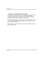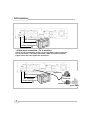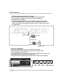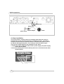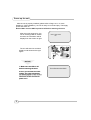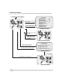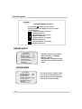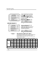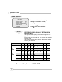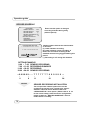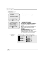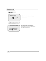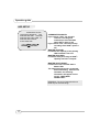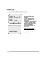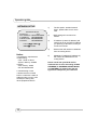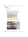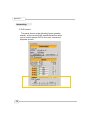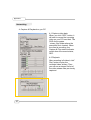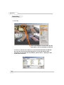
1
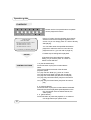
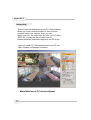
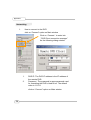
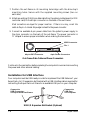
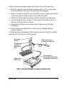
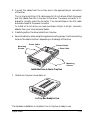
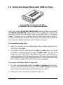
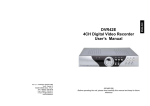
Digital Video Recorder The Networking model Index Introduction to Digital Video Recorder------------------2 Front panel buttons-------------------------------------------3 Rear panel buttons ------------------------------------------4 DVR installation:video output connection--------------5 DVR installation:video input connection----------------5 DVR installation:sensor installation----------------------6 DVR installation:alarm installation------------------------7 Power up the unit --------------------------------------------8 On-screen display--------------------------------------------9 Operation guide:Main menu-------------------------------10 Operation guide:Camera select---------------------------10 Operation guide:Record select----------------------------11 Operation guide:Record mode----------------------------11 Operation guide:Record frame-rate----------------------12 Operation guide:Video quality-----------------------------13 Operation guide:Record schedule------------------------14 Operation guide:Sub menu-password change--------15 Operation guide:Sub menu-time set---------------------16 Operation guide:Sub menu-display format-------------16 Operation guide:HDD setup -------------------------------17 Operation guide:Sensor setup ----------------------------18 Operation guide: How to start Motion detection recording------------------------------------------------------19 Operation guide:Networking setup-----------------------20 Operation guide:Playback ----------------------------------21 Appendix I Regulatory --------------------------------------22 Appendix II Networking ------------------------------------23 Introduction Introduction to Digital Video Recorder (DVR) The digital video recorder (DVR) is for recording/retrieving video streams from up to 4 channels at the same time. It adopts a digital image compression technology to compress the input channel video streams, and uses HDD to record the compressed video stream. The following operation guide explains how to operate/manage the DVR, and the following installation guide explains how to install DVR at your home or HDD into the DVR. Hope you enjoy it, use it to protect your home, and eventually make your home as SAFE HOME. 2 Front Panel 8 9 10 11 4 5 3 2 6 7 1 15 14 13 12 1. (Menu) button: press to display Operation menu option 2. z(Recording button): press to start recording. 3. (Stop recording/playback button):press stop recording/playback (the authorized password is requested upon stopping record; the default password is 111111) 4. (Fast forward button): press to play the recorded stream faster. 5. f (Playback button): press to start playback 6. (Pause button): press to pause the video playback 7. Reverse:press to playback backward 8. Channel 1 button: press to select channel 1 9. Channel 2 button: press to select channel 2 10. Channel 3 button: press to select channel 3 11. Channel 4 button: press to select channel 4 12. 田 All channels button: press to select all channels display 13,14. up down buttons: press to change menu field 15. (Select) button: press to change the setting value or enter into a sub menu 3 Rear Panel 2 1 3 1. 2. 3. 4. 5. 6. 7. 8. 9. 10. 11. 4 4 5 6 7 8 9 10 11 S Video Video output Monitor : Second Video output Video input Video loop-through Sensor input/alarm output: 4 sensor inputs and one alarm output NTSC/PAL switch DC-in (12Voltage) Audio input/output LAN Power switch DVR Installation BNC connection Or through S-Video connection 1.Video input connection ( TV or monitor) Please connect TV(monitor) to the unit over the Video output connector. The unit provides 1 x S-Video input and 2 x BNC connector.The above Figure shows the video signal line connection. Signal Line BNC connection Or through S-Video connection Camera Power line AC/DC adaptor power outlet 5 DVR Installation 2. Video output connection ( Camera) Please connect Camera to the unit over the Video input connector. The unit provides 4 x BNC connectors.The camera installation Procedures are as following: i. Connect the video signal line: connect the video signal line to the unit ii.Connect camera power line: Connect camera’s adaptor to camera, and plug in the adaptor. The complete connection with a camera will be shown as figure below Signal Line Sensor Power line AC/DC adaptor power outlet 3.Sensor Installation The unit provides 4 sensor input for 4 channels. The sensor Installation procedures are as follows. There are two simple steps For the installation of the sensors. i. Connect the sensor signal line: Connect the video signal line to the unit. The Sensor signal terminal is at the unit’s back panel ii.Connect the sensor adaptor jack into the sensor, and plug in the adaptor. CH1 6 CH2 CH3 CH4 Alarm out DVR Installation Signal Line Power line power outlet AC/DC adaptor Alarm 4. Alarm installation The unit provides 1 internal switch for sounding alarm when the sensor is Activated due to the unwanted entrance of anonymous visitor. The switch Is open at normal state, but, when the alarm is activated, the switch is closed So that the alarm gets the power. The circuitry is shown as above figure. There are two simple steps for the installation of the alarm i. Prepare the power supply:the alarm needs a power supply, the power supply comes with the alarm ii.Connect the alarm power line:the alarm power line is connected to the alarm switch terminal. 7 Power up the unit After the unit is properly installed ( please refer to Page 15-17 for more detailed on DVR installation.), the unit is ready to record and play. Then apply power and switch on. Notice: Make sure the HDD is powered off before removing the drive After the unit is powered on, the unit is checking HDD for several seconds, the information will be displayed on the screen as right: The unit will enter into real-time display mode shown as the right figure: HDD CHECKING OK CH1 CH3 CH3 CH4 NOTICE 1. Make sure the HDD is off before removing the drive 2.Once you resume the initial setting, the right information will be displayed on the screen. Then turn off the unit and rerepower on it. 8 Turn off and on the DVR! On-Screen Display 1. Power on the system Press button to open OSD menu as right CH1 CH3 CH3 CH4 Press button to exit OSD menu to real-time display MAIN MENU CAMERA SELECT 1234 RECORD SELECT 1234 RECORD MODE 田 RECORD FRAMERATE 30 VIDEO QUALITY HI RECORD SCHEDULE SUB MENU HARD DRIVE SETUP SENSOR SETUP NETWORK SETUP OSD Mode Display Pressz button to start recording Press button to stop recording( password is requested!) ● CH1 ● CH3 ● CH3 ● CH4 Recording Mode Display Pressf button to search time or event to playback Press button to exit the menu SEARCH TIME HDD: MASTER 04/03/24 13:24:21-04/03/24 13:44:54 >01 TIME 04/03/24 13:24:21 >02 TIME 04/03/24 13:30:55 >03 TIME 04/03/24 13:40:54 (¿À) MOVE,() CHANGE,(f)PLAY SEARCH MODE Press f button to start playing Press button to stop playback CH1 CH3 CH3 CH4 PLAYBACKMODE 9 Operation guide MAIN MENU MAIN MENU CAMERA SELECT 1234 RECORD SELECT 1234 RECORD MODE 田 RECORD FRAMERATE 30 VIDEO QUALITY HI RECORD SCHEDULE SUB MENU HARD DRIVE SETUP SENSOR SETUP NETWORK SETUP Press to display menu option shown as right figure. Operation Buttons --- press to display menu option. ST--- press to change menu field or change the unit’s configuration values. --- press to select menu item or confirm the selection. ¾Please stop recording or playback before you enter into OSD menu. ¾You will be requested to enter password, while stopping recording. CAMERA SELECT MAIN MENU ¾ CAMERA SELECT 1234 RECORD SELECT 1234 RECORD MODE 田 RECORD FRAMERATE 30 VIDEO QUALITY HI RECORD SCHEDULE SUB MENU HARD DRIVE SETUP SENSOR SETUP NETWORK SETUP The unit provides 4 camera inputs. You can use channel buttons on the front panel to select specified channel for real-time display. You can use “” button or channel buttons for different combinations for channel display. Example: 1. When you choose (----), all cameras are off 2. When you choose (1234), all cameras are displayed. 3. When you choose (---4), only the fourth channel is displayed. NOTICE VIDEO LOSS ! “VIDEO LOSS” signal will be displayed, and the built-in alarm buzzer will be triggered to sound, while no video connection or connection failure. 10 Operation guide NOTICE Channel Display Control In each mode(回) mode, you can use the following buttons to display Full-screen format of each channel. Channel 1 button: Full screen display of channel 1 Channel2 button: Full screen display of channel 2 Channel 3 button: Full screen display of channel 3 Channel 4 button: Full screen display of channel 4 RECORD SELECT MAIN MENU CAMERA SELECT 1234 ¾RECORD SELECT 1234 RECORD MODE 田 RECORD FRAMERATE 30 VIDEO QUALITY HI RECORD SCHEDULE SUB MENU HARD DRIVE SETUP Selecting channel on this menu option is same as “CAMERA SELECT” options. Only selected camera will record real-time events during recording period RECORD MODE ¾ 11 MAIN MENU CAMERA SELECT 1234 RECORD SELECT 1234 RECORD MODE 田 RECORD FRAMERATE 30 VIDEO QUALITY HI RECORD SCHEDULE SUB MENU HARD DRIVE SETUP The unit provides 4 camera inputs. You can use channel buttons on the front panel to select specified channel for real-time display. Operation guide There are two kinds of recording mode : 回(each mode; full screen mode)&田 (quad screen mode). when you set to 回mode, you can view the full-screen display of one specified channel. When you set to 田 mode, quadscreen will be displayed. Please use ¿À buttons of front panel to select mode and then enter to confirm the selection MAIN MENU CAMERA SELECT 1234 RECORD SELECT 1234 ¾RECORD MODE 田 RECORD FRAMERATE 30 VIDEO QUALITY HI RECORD SCHEDULE SUB MENU HARD DRIVE SETUP RECORD FRAMRATE There are 9 different frame rate settings for operation: (30fps,15fps,10fps,7fps,5fps,4fps,3 fps,2fps,1fps; But the unit is set to 30fps in the factory ) MAIN MENU CAMERA SELECT 1234 RECORD SELECT 1234 RECORD MODE 田 ¾RECORD FRAMERATE 30 VIDEO QUALITY HI RECORD SCHEDULE SUB MENU HARD DRIVE SETUP NOTICE Please use ¿À buttons of front panel to select mode and then enter to confirm the selection RECORDING FRAME RATE TABLE The higher the record frame rate is, the more natural look will be displayed on the screen on playback mode. But the lower the record frame rate is, the more you can save the space on HDD. The following is the recording fps table for your reference 1 2 3 4 5 7 10 15 30 1CH 1 2 3 4 5 7 10 15 30 回 2CHs 0.5 1 1.5 2 2.5 3.5 5 7.5 15 MODE 3CHs 0.33 0.67 1 1.33 1.7 2.33 3.33 5 10 4CHs 0.25 0.5 0.75 1 1.25 1.75 2.5 3.75 7.5 1 2 3 4 5 7 10 15 30 Frame/Second 田MODE 12 Operation guide VIDEO QUALITY MAIN MENU CAMERA SELECT 1234 RECORD SELECT 1234 RECORD MODE 田 RECORD FRAMERATE 30 ¾VIDEO QUALITY HI RECORD SCHEDULE SUB MENU HARD DRIVE SETUP NOTICE There are 3 different video quality settings for operation: Normal, Low, High Please use ¿À buttons of front panel to select mode and then enter to confirm the selection DIFFERENT VIDEO QUALITY SETTINGS ON HDD CAPACITY The higher the video quality is, the clearer images the unit plays. But the lower the video quality is, the more you can save the space on HDD. The following is the recording time vs video quality settings table for your reference 1 2 3 4 5 7 10 15 30 HI 733 H 366 H 244 H 183 H 146 H 104 H 73H 48H 25H NORMAL 992 H 496 H 331 H 248 H 198 H 141 H 99H 66H 33H LO 115 3H 576 H 384 H 288 H 230 H 153 H 115 H 76H 39H HI 556 H 279 H 185 H 139 H 111 H 80H 56H 37H 19H NORMAL 763 H 382 H 255 H 190 H 152 H 110 H 76H 51H 25H LO 877 H 438 H 292 H 220 H 175 H 125 H 88H 58H 29H Frame/Second 回 MODE 田 MODE The recording hours on 80GB HDD 13 Operation guide RECORD SCHEDULE MAIN MENU CAMERA SELECT 1234 RECORD SELECT 1234 RECORD MODE 田 RECORD FRAMERATE 30 VIDEO QUALITY HI ¾RECORD SCHEDULE SUB MENU HARD DRIVE SETUP SENSOR SETUP PROGRAMMED RECORD +TTTSSTTTTTTTTT+ 0 3 6 9 12 15 18 21 24 PRESS (¿À), THEN ( ) PRESS() TO EXIT Enter into this option to change a recording schedule during a day (24-hour period) . Numbers above indicate the time duration of 24 hours. (T) Letter indicates recording. (S) Letter indicates sensor recording. It means the unit starts recording as the attached sensors being triggered during this period. (--) Recording is off during this duration. SETTING EXAMPLE: 0:00 ~ 7:00 SENSOR RECORDING 7:00 ~11:00 RECORDING DISABLED 11:00 ~18:00 RECORDING 18:00 ~24:00 SENSOR RECORDING +SSSSSS----T T T T T T T S S S S S S + : : : : : 0 6 11 18 24 NOTICE SENSOR RECORDING INSTALLATION The unit provides 4 alarm inputs which can be configured as normal close, normal open, motion detection +NC and motion detection+NO over “SENSOR SETUP” menu option. (Please refer to P. 18 for the sensor setup). After the sensor configuration, please go back to “ RECORD SCHEDULE” menu to enable sensor recording. 14 Operation guide SUB MENU SUB MENU ¾PASSWORD CHANGE TIME SET DATE DISPLAY FORMAT Enter into this option to change password, time /date setting, date format. PRESS (¿À), THEN ( ) PRESS() TO EXIT PASSWORD CHANGE CURRENT PASSWORD: ------NEW PASSWORD:------PASSWORD CONFIRM:-------PRESS (¿À), THEN ( ) PRESS() TO EXIT NOTICE 15 PASSWORD CHANGE . You enter into “PASSWORD CHANGE”, a password change input menu replaces the “SUB MENU” (The default password is 111111) When the new password is accepted, the board will flash the following screen message: PASSWORD changed!!! The message will blink 5 times. Then the display goes back to SUB MENU. If the password was not accepted, the unit will automatically return to SUB MENU. FRONT PANEL BUTTONS DEFINITION means “1” means “5” means “2” d means “6” means “3” means “7” means “8” means “4” means “9” means “0” Operation guide TIME SET TIME 2004/03/21 03:23:21 PRESS (¿À), THEN ( ) PRESS() TO EXIT Enter into this option to change date and hour. DATE DISPLAY FORMAT DATE DISPLAY FORMAT PRESS (¿À), THEN ( ) PRESS() TO EXIT 16 The unit provides yyyy/mm/dd or dd/mm/yyyy variant which depends on the regional preference. Operation guide HDD SETUP HARD DRIVE SETUP OVERWRITE ENABLED YES MASTER HDD SIZE 40000MB MASTER HDD USED 0MB 0% MASTER HDD FORMAT SLAVE HDD SIZE PRESS (¿À), THEN ( ) PRESS() TO EXIT OVERWRITE ENABLED: If you choose “YES”, the unit will continue recording and overwrite the recorded data when HDD’s space is full If you choose “NO”, the unit will stop recording while HDD’s space is full MASTER HDD SIZE: It indicates the capacity of the primary HDD installed in the unit MASTER HDD USED: It indicates how percentage of HDD’s capacity has been occupied. MASTER HDD FORMAT: It erases all of the recorded data in Master HDD The authorized password is requested before formatting, after the unit formatted, the following information will appear on the screen “HARD DISK FORMATTED” . REMARKS: The unit is featured with one HDD only for the time being! 17 Operation guide SENSOR SETUP SENSOR SETUP SENSOR RECORD TIME 15 ALARM OUT TIME 20 CHANNEL-1 TYPE:MOTION + N-C CHANNEL-2 TYPE:MOTION + N-O CHANNEL-3 TYPE:NORMAL CLOSE CHANNEL-4 TYPE:NOT INSTALLED PRESS (¿À), SENSOR RECORD TIME: Recording duration once sensor Being triggered. ALARM OUT TIME: It controls how long ( in second) the alarm sounds after being triggered. THEN ( ) PRESS() TO EXIT SENSOR TRIGGER MODES: The unit provides 5 different modes for variant uses: 1.Not installed. 2. Normal open. 3. Normal close. 4. Motion +N-C 5. Motion + N-O In normal open mode, the cable line Connected between the sensor and the unit is cut off by an intruder, the unit starts recording. In normal close mode, the cable line connected between the sensor and the Unit is cut off by an intruder , the unit stops recording 18 Operation guide How to operate Motion detection recording SENSOR SETUP SENSOR RECORD TIME 15 ALARM OUT TIME 20 CHANNEL-1 TYPE:MOTION + N-C CHANNEL-2 TYPE:MOTION + N-O CHANNEL-3 TYPE:NORMAL CLOSE CHANNEL-4 TYPE:NOT INSTALLED PRESS (¿À), THEN ( ) PRESS() TO EXIT PROGRAMMED RECORD +TTTSSTTTTTTTTT+ 0 3 6 9 12 15 18 21 24 PRESS (¿À), THEN ( ) PRESS() TO EXIT 19 Follow the steps as below to activate motion-detection recording. 1.Please go to “SENSOR SETUP” menu as the left figure shown. 2. Select out the motion option. 3. After the selection, please be back to MAIN MENU and go to “PROGRAMMED RECORD” to power on the alarm setting. Notice: The setting under “PROGRAMMED RECORD” is necessary for starting the operation of motion detection recording. Operation guide NETWORK SETUP NETWORK SETUP ACCEPT IP YES MAC ADDRESS 03:01:01:01:25:46 IP ADDRESS 192.168.000.090 SUBNET MASK 255,255,255,000 GATEWAY 192.168.000.001 PRESS (¿À), 1) The first option “enabled network client”, please make sure is set to YES 2) MAC setting will not need to be altered. 3) *IP address (a static IP address ) will need to be set to the DVR IP address you planning to allocate to, while you connect to Internet. 4) Subnet mask will need to be obtained from the routing device. 5) #Gateway IP address (IP address A) will need to be obtained from the routing device. THEN ( ) PRESS() TO EXIT Notice: 1.PC Minimum requirements of Networking : CPU: 1 GHZ or above System Memory: 256MB or above VGA memory: 32MB OS: Window2000/XP 2. Please assign 14337, 14338 to the Port to install DVR in a LAN with a static IP address under a router ( with firewall) for sharing with other equipments like PC. 20 Please check with your M.I.S staff or administrator to enter the setting of MAC ADDRESS, IP ADDRESS,SUBNET MASK and GATEWAY Or please refer the left figure as a example for your reference Operation guide PLAYBACK Please use the front panel buttons to operate various playback functions. SEARCH TIME HDD: MASTER 04/03/24 13:24:21-04/03/24 13:44:54 >01 TIME 04/03/24 13:24:21 >02 TIME 04/03/24 13:30:55 >03 TIME 04/03/24 13:40:54 (¿À) MOVE,() CHANGE,(f)PLAY NOTICE Press “f” button, then the playback time /events selection menu as the left figure appears on the screen. Or you can simply press “f” twice to directly start playing. You can either enter the specified time/date to playback or select the event or even view the playback over PC ( you can refer to page.13) 1. Please stop recording before playback. 2. Because the events selection is default setting, so you need to press “” button to switch to time selection. CONTROL BUTTONS 1. (fast forward button): Press this button to play the recorded stream faster. The unit provides three levels of fast forward playback speed: 1: play one time faster (x1), press “” button 2: play two times faster (x2) than the normal play 3: play four times faster (x4) than the normal play 4: play thirty-two times faster (x32) than the normal play 5: play sixty-four times faster (x64) than the normal play 2. (reverse button): Press this button to play the recorded stream backward. Remarks: the reverse playback speed depends on the fps, the number of the recorded channel, the video quality. 3. (pause button) : Press this button to pause the playback, or to advance one single frame upon pause mode. 21 Appendix I. Regulatory FCC Certification This equipment has been tested and found to comply with the limits for a class A digital device, pursuant to Part 15 of the FCC rules. These limits are designed to provide reasonable protection against harmful interference when the equipment is operated in a commercial environment. This equipment generates, uses, and can radiate radio frequency energy and, if not installed and used in accordance with the instruction manual, may cause harmful interference to radio communications. Operation of this equipment in a residential area is likely to cause harmful interference in which case the user will be required to correct the interference a the own expense. CE Mark This product is marked with the CE symbol and indicates compliance with all applicable directives. 22 Appendix II. Networking This Unit with the dedicated remote PC client software allows you from a remote location to view live and recorded video over Internet. Also, you can capture,convert the video from the unit into AVI file or JPEG file, or play the stored video later on. Please follow the instructions below to use PC client. After you install PC client software into your PC, the Main window will appear on screen: Main Window of PC client software 23 Appendix II. Networking 1. How to connect to the DVR click on “Connect” option on Main window Click on “Connect “ to enter into “DVR Client connection manager” As the following dialog window: 1. 2. DVR IP: The DVR iP address is the IP address of the remote DVR. Password : The password is same password used for formatting the DVR’s Hard Drive. The default value is 111111 click on “Connect” option on Main window 24 Appendix II. Networking 2. Connection Status: When successfully connected, you would see” Connected” sign. This window also displays DVR IP address and shows changes of connection speed. • To disconnect, simply click “ Disconnect “ • To close the application, click “ Close Window” button 25 Appendix II. Networking 3. DVR control The panel shown as the following figure operates exactly as the remote DVR operational button allow you to control remote DVR to live view, record and playback as well. 26 Appendix II. Networking 4. Capture & Playback on you PC 4-1 Capture video data When you click “REC” button, it will start to record the incoming video on your PC hard disk. The DVR client creates “ steam_files”folder where the execution file is located. When the client is recording, the Capture & Play status indicator would show the current status, REC. 4-2 Playback After recording is finished, click” Play” button to play the recorded video stream. Then you will see a stream file list of the video stream files previously captured. 27 Appendix II. Networking 5. DVR management This option enable you to just remote DVR’s operation setting : Video Quality, Record Frame rate, Alarm On Duration, Alarm record Duration, Input Channels, Record Channels, DVR system time setting and Record Schedule. All of settings operate as you do with DVR itself. Notice: For the record mode change can be made only on DVR, so the display shows the current DVR record mode on connection. 28 Appendix II. Networking 6. AVI file Click on this button to convert the real-time video data or the recorded data into AVI file 6. Click on “ AVI save as” button to convert the desirable data into AVI file, then you will see the following dialog box for saving the AVI file. After specifying the file name and confirmation, please click on “ Backup to AVI” to start the conversion. 23 Removable Docking Modules for IDE or USB Devices Super Rack Models: VP-10LSFU-100/133 VP-10KPFU-100/133 VP-410LS2FU-100/133 VP-410KP2FU-100/133 VP-15-100/133 Super Rack 1-1 1-1 Introduction ........................................................................ 1-3 Super Rack Features .................................................... 1-4 System Requirements ................................................... 1-4 Unpacking Your Super Rack ......................................... 1-5 IDE Basics .................................................................... 1-5 USB Basics ................................................................... 1-5 1-2 Hardware Installation .......................................................... 1-6 Super Rack Components .............................................. 1-5 Installing the Super Rack Out-Frame ............................. 1-7 Installation for USB Interface ......................................... 1-8 Mounting a Drive in the In-Tray Box (VP-15) ................ 1-10 1-3 Using the Super Rack with IDE Devices ........................... 1-12 1-4 Using the Super Rack with USB Devices .......................... 1-13 1-2 Super Rack 1-1 Introduction Congratulations on your purchase of an ATA 33/66/100/133 Super Rack Removable Docking Module. The Super Rack is a convenient, versatile solution for portable, interchangeable usage of both IDE and USB devices with your USB-equipped PC or Mac computer. The Super Rack is form-fitted for a standard 5.25" half-height bay. When installed in your computer, it provides the ATA 33/66/100/133 interface for hot-swapping any IDE in-tray box (with IDE devices such as 3.5”/2.5” HDD, LS-120, MO, TR-4 tape, ATA flash memory reader, and zip drives installed) or any USB in-tray box (such as hub, fax/modem, memory card readers and TV/FM/capture/cable models). The Super Rack includes an IDE interface in-tray (VP-15) which can accept most half-height 3.5" and 2.5" drives (with separately purchased adapter cables). Not being limited by memory size, you can install any capacity drive. USB interface in-tray box models must be purchased separately. This manual will guide you through the installation of the following Super Rack Removable Docking Modules. Super Rack Models: VP-10LSFU VP-10KPFU VP-410LS2FU VP-410KP2FU VP-15 IDE/USB interface, Latch-lock/Slide Switch with One Fan IDE/USB interface, Key-lock Power Switch with One Fan IDE/USB interface, Latch-lock/Slide Switch with Two Fans IDE/USB interface, Key-lock Power Switch with Two Fans IDE interface, In-Tray Box Super Rack Compatible USB In-tray Models: VP-15H VP-15H2 VP-15M VP-15CF VP-15SM VP-15MS VP-15MMC VP-15TV Super Rack USB 1.1 4-port Hub USB 2.0 4-port Hub (requires USB 2.0 equipped computer) USB Fax/Modem USB CompactFlash Memory Card Reader USB SmartMedia Memory Card Reader USB Memory Stick Memory Card Reader USB MMC Memory Card Reader USB TV/FM/Capture/Cable 1-3 Model Number Code Descriptions for Ordering Information: VP-1 0 L S F S 1 1 2 3 4 5 6 7 2 3 4 5 6 7 ViPowER .................. Interface Type .......... Body ........................ Lock Type ................ Power Switch ........... Cooling Fan ............. USB Solution ........... VP 1 = IDE, 2 = SCSI, 3 = Wide SCSI 2 = Out-Frame, 5 = In-Tray Box, 0 = Frame + Tray L = Latch-lock, K = Key-lock S = Latch Switch, P = Power IC Switch F = Fan U = USB Super Rack Features • Compatible with PC or Mac tower or desktop models, external subsystem & RAID system cases • Form-fitted for a standard 5.25-inch half-height bay • IDE in-tray box (VP-15) enables portable use of fixed 3.5-inch and 2.5-inch (with separately purchased adapter cables) hard disk drives, LS-120, MO, TR-4 tape, zip and other IDE and ATAPI devices • USB support for portable use of USB hub, fax/modem, CF/SM/MS/ MMC/Micro Drive/SD memory card readers and TV/FM/Capture in-tray modules • Convenient pull-out handle • Safety lock feature • Power on/off feature • LED indicator for power and drive activity • Built-in cooling fan • The in-tray box is interchangeable between all models • Fully compatible with Windows® 98 or later; Mac OS 8.6 or later • Dimensions: 8.4" (D) x 5.8" (W) x 1.6" (H) System Requirements • Tower or desktop models, external subsystem & RAID system cases with standard 5.25-inch half-height drive bay • USB feature requires a USB-equipped PC or Mac computer with available USB port 1-4 Super Rack Unpacking Your Super Rack Before installing the Super Rack, verify that the following items are included in the carton. If any parts are damaged or missing, please contact your local dealer or sales representative immediately. 1. 2. 3. 4. 5. One Super Rack Removable Docking Module Twelve mounting screws 2 keys (for key-lock models only) I/O expansion bracket with USB connectors One user’s guide IDE Basics IDE is an acronym for Integrated Device (Drive) Electronics and is sometimes referred to as an ATA (AT Attachment) interface. It is the most commonly used interface for hard disk drives installed on personal computers. Other devices like CD-ROM, tape, optical drives, and so on have adapted a variation called ATAPI (ATA Packet Interface) and can be intermixed with standard IDE drives because they use the same cabling and electrical interface. Most systems today have two IDE channel connectors that are typically referred to as primary and secondary ports. Each IDE port can have a maximum of two devices that must be uniquely identified, typically by the setting of a jumper as a ‘master’ or ‘slave’ device. USB Basics USB is an acronym for Universal Serial Bus, a standard developed to replace the aging serial and parallel ports on existing computers. Using only one IRQ and designed as a hub architecture, it can support up to 127 devices. After loading the appropriate device driver(s), USB offers true plug-n-play and hot-swapping capability. A USB device can be plugged and unplugged from most systems at any time and anywhere on the USB network. All connected devices on the bus can run simultaneously. First release version USB 1.1 is defined as an intermediate speed bus and operates at either 12 Mbps or 1.5 Mbps, depending on the attached device. Typical USB devices include printers, modems, pointing devices, scanners, cameras, keyboards, memory card readers, speakers and more. The latest release version USB 2.0 is designed to increase data throughput up to 480 Mbps... 40 times faster than USB 1.1. Supporting multiple high-speed peripherals without worrying about a bandwidth bottleneck, it is also backward compatible with all USB 1.1 hardware. Super Rack 1-5 1-2 Hardware Installation The Super Rack Docking Module is designed to install in any PC or Mac computer with an available 5.25-inch half-height drive bay. General instructions for installing the Super Rack are given since the design of computer cases varies. Refer to your computer’s manual whenever in doubt. Super Rack Components The Super Rack is comprised of two components: Out-Frame [VP-12LS (KP) FU] In-Tray Box (VP-15) Mounting Holes Power ON/OFF LED Indicator Latch-Lock/Power Switch Drive Activity LED Indicator Latch-Lock Super Rack Out-Frame Model (VP-12LSFU) Mounting Holes Key-Lock/Power Switch Power ON/OFF LED Indicator Drive Activity LED Indicator Key-Lock Super Rack Out-Frame Model (VP-12KPFU) 1-6 Super Rack Power Connector Data Interface Cable Bottom Mounting Holes Side Mounting Holes Handle Removable Front Panel for Removable Media Drives Super Rack In-Tray Box VP-15 (with cover removed) Installing the Super Rack Out-Frame 1. Turn OFF the power to your computer and any other connected peripheral devices. Follow the precautions for static electricity discharge: • Discharge any static electricity build up in your body by touching a grounded metal surface such as the computer case, if plugged in. • During installation procedures, avoid any contact with internal parts. 2. Unplug the power cord from the back of the computer. 3. Remove your computer’s cover. 4. Remove the computer’s front cover plate from the 5.25-inch drive bay you plan to install your Super Rack into. 5. Remove (separate) the Super Rack in-tray box from the out-frame by lifting the handle and pulling it out. 6. Slide the out-frame into the selected 5.25-inch drive bay of your computer. Mounting Screws Out-Frame (All Models) Mounting Screws Install the Super Rack Out-Frame into the Drive Bay Super Rack 1-7 7. Position the out-frame so its mounting holes align with the drive bay’s mounting holes. Secure with the supplied mounting screws (two on each side.) 8. Attach an existing IDE 40-pin data cable from the system motherboard (or IDE controller card) to the 40-pin connector on the back of the out-frame. Most connectors are keyed for proper insertion. If there is no key, orient the cable so the pin-1 colored stripe edge is closest to the power connector. 9. Connect an available 4-pin power cable from the system’s power supply to the 4-pin connector on the back of the out-frame. The power connector is ‘D’ shaped to ensure proper orientation when making the connection. USB Connector Pin 1 40-pin IDE Connector 4-pin Power Connector Out-Frame Data Cable and Power Connectors Continue to the next section before replacing the computer’s cover and reconnecting the power and other external cabling. Installation for USB Interface Your computer must be USB-ready in order to implement the USB feature of your Super Rack. An I/O expansion slot bracket with a USB interface cable is supplied for connecting the Super Rack out-frame to an available USB port on your computer. Connect to USB Connector on Super Rack Out-Frame Connect to USB Port on Computer USB I/O Expansion Slot Bracket (Optional) 1-8 Super Rack Perform the following steps to enable the USB function of the Super Rack. 1. With the computer cover removed, ensure the power is OFF, and all power cords and cables from the back of the computer are unplugged. 2. Select an unused I/O expansion slot at the back of your computer and remove its slot cover. Save its screw for securing the USB slot bracket. 3. Install the USB slot bracket and secure with the previously removed screw. 4. Connect the small 5-pin connector on the bracket to the USB connector on the back of the Super Rack out-frame. 5. Replace the computer’s cover and reconnect the power and other cable connections. 6. Plug the bracket mounted USB connector into any available USB port on your computer. The following figure illustrates the USB connectors used to connect the installed Super Rack to the USB port on the computer. Mounting Screw USB Connector to Computer’s USB Port USB Bracket Installed in Expansion Slot Super Rack Out-Frame Connection to Super Rack Out-Frame (Installed in Computer) USB Connections Between Computer and Super Rack Super Rack 1-9 Mounting a Drive in the In-Tray Box (VP-15) Proceed with the following steps to install a 3.5-inch drive device in the in-tray box. (Note: a special adapter kit is required in order to install a 2.5-inch drive.) 1. Remove the in-tray box cover by sliding it towards the back of the unit. Slide Cover Off Remove the In-Tray Box Cover 2. If you plan to install a drive that features removable media such as a zip, TR-4 tape, MO, LS-120 drive, or ATA Flash memory reader, remove the center part of the front panel. Center Part of Front Panel Removed Remove Front Panel for Removable Media Drives IMPORTANT 3. If you are installing a new hard drive into the in-tray box, you may need to configure the drive before you install it. Refer to the drive manufacturer’s documentation and configure the drive as ‘Master’, ‘Cable Select’, or ‘Slave’ depending on the configuration of your computer. After you complete this installation, you may also need to re-configure the computer’s BIOS Setup to make the drive functional in the system. 1-10 Super Rack 4. Connect the cables from the in-tray box to the appropriate pin connectors of the drive. The in-tray box’s 40-pin IDE cable supports 3.5-inch drives. Attach the power and IDE cables from the in-tray box to the drive. The power connector is ‘D’ shaped to correctly orient the connector. The colored stripe on the IDE cable should be closest to the power connector. To install a 2.5-inch drive, you must purchase a ‘44-pin to 40-pin’ connector adapter from your local computer dealer. 5. Carefully position the drive inside the in-tray box. 6. Secure the drive in place using the supplied mounting screws. Use the mounting holes on the sides or bottom, depending on the design of the drive. Power Cable Colored Stripe Mounting Screws Data Cable Mounting Screws Install the Drive in the In-Tray Box 7. Slide the in-tray box’s cover back on. In-Tray Box Ready for Use The hardware installation is complete. Your in-tray box is ready to use. Super Rack 1-11 1-3 Using the Super Rack Latch-Lock models VP-10LSFU/VP-410LS2FU, and Key/Power Lock models VP-10KPFU/VP-410LS2FU support hot-swapping. The power to your computer can be ON when the drive is inserted or removed. Use the Latch-Lock switch or Key/ Power Lock keyswitch to turn power to the drive ON after inserting it, and OFF before removing it. To insert the in-tray box: 1. Insert the in-tray box (with drive installed) into the installed Super Rack out-frame and push firmly until the drive is seated. 2. For Latch-Lock models, slide the latch-lock left, to the lock position. For Key/ Power Lock models, insert the key and turn key to the right to lock. The LED on the Super Rack should light after a slight delay. The installed in-tray’s device is ready to use. Slide-lock Lock Position Key-lock Lock Position To remove the Super Rack in-tray box: 1. For Latch-Lock models, slide the latch-lock right, to the unlock position. For Key/ Power Lock models, insert the key and turn key to the left to unlock. Note that the power LED on the Super Rack’s out-frame should now be OFF. 2. Gently pull on the out-frame box’s handle to slide it out. Slide-lock Unlock Position 1-12 Key-lock Unlock Position Super Rack 1-4 Using the Super Rack with USB In-Trays Example USB 1.1 4-port Hub ( VP-15H ) (Comes with USB I/O Expansion Slot Bracket) Latch-Lock models VP-10LSFU/VP-410LS2FU, and Key/Power Lock models VP-10KPFU/VP-410LS2FU support plug-n-play, hot-swapping of USB in-tray devices such as USB hub, fax/modem, memory card readers and TV/FM/capture models. The power to your computer can be ON when the in-tray is inserted or removed. Use the Latch-Lock switch or Key/Power Lock keyswitch to turn power to the in-tray box ON after inserting it, and OFF before removing it. To insert the in-tray box: 1. Insert the in-tray box into the installed Super Rack out-frame and push firmly until the in-tray is seated. 2. For model VP-10LSFU, slide the latch-lock left, to the lock position. For model VP-10KPFU, insert the key and turn key to the right to lock. The LED on the Super Rack should light after a slight delay and you may be prompted for a onetime installation of its USB device driver when first used. Follow the prompts and the device is ready for plug-n-play use from then on. Note that any device used with a USB Hub model (VP-15H/VP-15H2) is hot-swappable. To remove the Super Rack in-tray box: 1. For Latch-Lock models, slide the latch-lock right, to the unlock position. For Key/ Power Lock models, insert the key and turn key to the left to unlock. Note that the power LED on the Super Rack’s out-frame should now be OFF. 2. Gently pull on the out-frame box’s handle to slide it out. Super Rack 1-13 1-14 Super Rack