1
US006642852B2
(12)
(54)
United States Patent
(10) Patent N0.:
Dresti et al.
(45) Date of Patent:
REMOTE CONTROL DEVICE WITH
OTHER PUBLICATIONS
(75) Inventors? Mauro Dresti, West covina, CA (Us);
Patrick H. Hayes, Mission Viejo, CA
(Us)
_
Dataprobe, “Serial Controlled A/C Power Strips Operation
Manual”, Oct 16, 2002*
AMX Instruction Manual, PC Presenter, Aug. 2001, pp.
_
i—35, AMX, Richardson, Texas.
(73) Asslgnee: Umversal Electromcs Inc” Cypress’
IntelliControl, Home Theater Automation System, 1999, 4
CA (Us)
_
pgs., Niles Audio Corporation, Miami Florida.
_
( 4 ) Notice:
Nov. 4, 2003
6,496,927 B1 * 12/2002 McGrane et a1. ............ .. 713/1
APPLIANCE POWER AWARENESS
_
US 6,642,852 B2
_
_
_
120V AC PoWer Switching Systems, 2001, 3 pgs., Niles
Sub]ect' to any diisglaimecri, the tiermgf I21;
Audio Corporation, Miami, Florida'
{ftsenct liszxéenbe 0‘: a Juste 11“ er
AMX Instruction Manual, AXB—TC and AXB—TCR Tele
' ' '
( )
y
ays'
vision Controllers, Jul. 2001, pp. 1—33, AMX , Richardson,
Texas.
(21) Appl- No-3 10/087,078
(
22
-
)
_
Fld.
M
16
(65)
AMX, Instruction Manual, PCS and PCS2 PoWer Current
Sensors Jul. 2001 pp. i—13 AMX Richardson Texas.
.12002
ar
’
’
Prior Publication Data
Cl-7
Primary Examiner_Brian
(52)
H02] 3/00
US. Cl. .......................... .. 340/825.72; 340/310.08;
(58)
Field of Search .......................... .. 340/825, 825.71,
340/825.52; 307/38; 307/40
340/825.72, 310.01, 310.08, 825.52, 10.1,
10-2; 713/1
_
U.S. PATENT DOCUMENTS
*
5,051,720 A
5,097,249 A
5,642,101 A
5,815,086
4/1975 Kobayashi et a1. ....... .. 340/448
9/1991 Kittirutsunetorn
3/1992 Yamamoto
*
’
Jarosik
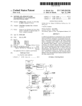
(57)
ABSTRACT
Acontrolling device having programming Which ensures an
not correspond to the desired poWer state, the controlling
device transmits a command to the appliance to effect a
6/1997 Stirk et al. ............... .. 340/3.51
.....
Zimmerman
Assistant Examiner—Clara Yang
(74) Attorney, Agent, or Firm—Mark R. Galis; Gary R.
appliance Will be placed into a desired poWer state. The
controlling device transmits a query message to a power
monitor associated With the appliance to obtain the current
poWer state of the appliance. If the current poWer state does
References Cited
3,878,512 A
’
* cited by examiner
. . . . . . . . . . . . . . . . . . . . . ..
(56)
’
tial), Jan. 23, 2002, 25 pgs.
US 2003/0164787 A1 Sep. 4, 2003
IIlt.
’
Smart PoWer Keys, Universal Electronics Inc. (Con?den
A
*
9/1998
Ivie et al.
5,943,228 A
*
8/1999
Kim .................... .. 340/825.72
. . . ..
change in the current poWer state of the appliance.
340/825.52
22 Claims, 14 Drawing Sheets
OTHER A/V
v EQUIPMENT
MONIIORED
14
,
RF QUERY
8t RESPONSE
/
,I’
U.S. Patent
>\<5E0
Nov. 4, 2003
Sheet 1 0f 14
552(\8v? 2
mu,
¥\(9
5261
>58km $a2 81
US 6,642,852 B2
U.S. Patent
Nov. 4, 2003
Sheet 3 0f 14
US 6,642,852 B2
310
33nd
320
@@ ©® ©@ @@
I-f’
@@.®QTQ
@@@@®
350
6
FIG. 3
U.S. Patent
Nov. 4, 2003
4-20
430
Sheet 4 0f 14
440
US 6,642,852 B2
450
$$$$
Device
RF Unit #
TV
0
Yes
0N
VCR
3
Yes
ON
None
Yes
Unknown
% CBL
Con?gured? Power status
410 4
AUX
4
Yes
OFF
2
SAT
None
No
Unknown
\
CD
1
Yes
Unknown
AMP
2
Yes
0N
TUN
None
No
Unknown
EXAMPLE DEVICE
STATUS TABLE
FIG. 4
\400
U.S. Patent
Nov. 4, 2003
Sheet 5 0f 14
US 6,642,852 B2
Setup code "979"
entered
+
.
Set RF unit 5 at table
=
entry"DeVi¢e-t)‘£>e"
Set DEW-‘We
to digit entered. with
Pressad
"Unknown"
device key
power siotus=
"Setup" key
pressed?
.<—
1!
Col! "Get
power Siam"
USER saw or
to upd?ie?"
DEVICE smus TABLE
table entnes-
uurr NUMBER-DEVICE
RElATIONSHIPS IN
REMOTE CONTROL
FIG. 5
U.S. Patent
Nov. 4, 2003
Sheet 6 6f 14
US 6,642,852 B2
Get system
power status
Transmit power
status enquiry
message
t
Enable receiver,
start timer
(N-1) registered
in table’?
Set statue of RF
m'tttg'é'go-t'éuitgius
”
'
OFF oslrepmed
sezustogus of RtF
unit
—1
in stu us
tobte to"Unknown"
N=N+1
N
Y
Shut down
receiver, stop
timer
@
REMOTE CONTROL "GET POWER STATUS" LOGIC FLOW
FIG. 6
U.S. Patent
Nov. 4, 2003
Sheet 7 0f 14
US 6,642,852 B2
"ALL 0N"key
- ressed
CoI|"Get
power status"
to update
table entries.
Set ?rst
device type
h 8 i
have discrete
power ON/OFF
codes?
Scan power
Status Table for
this device
Step to
next device
Power stctus=
"0N"?
Y
Transmit discrete
"Power 0N”
command
Transmit "Power
Toggle" IR code
+
REMOTE CONTROL "ALL ON" LOGIC
FIG. 7
U.S. Patent
Nov. 4, 2003
Sheet 8 0f 14
US 6,642,852 B2
Power"0N"
Look up Power
Status Table entry
for this device
Cail”(;et
power status"
to update
table entries.
Power status=
DIONII?
Y
‘rm-98m“ d‘sc?ete
Power
command
Transmit "Power
To ‘en
99
code
i
2
REMOTE CONTROL INDIVIDUAL "UNIT ON" LOGIC
FIG. 8
U.S. Patent
Nov. 4, 2003
;o._
‘:2m1Eew0z.aro8m:
imw?.t
Sheet 9 0f 14
US 6,642,852 B2
Emzg>o6Im
m
.QE
U.S. Patent
Nov. 4, 2003
Sheet 10 0f 14
US 6,642,852 B2
5?his5%=2868Eu>o
:Euo
%
NM
u
1mulit.
2!:
E3552+5:mVAv
\_I
1n
J
mm
J
5
w
V...
26
o_\f
a
xPnm
.svuI!
M
9:?cm
o
m
P
in‘n_?a
\\+
mm
N1
JL
%
N5m _o¢mnN__b)?
>w3
a;
c;
m9
a;
“RF5Ehg s
n.I\/@2231i
U.S. Patent
Nov. 4, 2003
Sheet 11 0f 14
US 6,642,852 B2
( Power on reset )
To set power threshold. _user
switches monitored device
7
°"- pl'essefsetup'lbuum-
Set default current
then switches monitored
dmw [hfgshgtd
device on and presses
"Setup"again(withln 20
seconds)
Y
Setup switch
activated?
1L=Current power
Message
draw value
received?
l
Start feedback
L£D flashing
‘
Power Status
enquiry?
Start timer
Read current
power draw
Set up
switch activated
again?
Power
draw threshold
value?
20 seconds
Set power
$totus=“0FF"
Set power
stotus="0N"
elapsed?
t
t
Read uni address
lH=current power
N(0 thru 7) from
draw value
switches
Threshold value:
j
‘
delautt
Threshokd vmue:
T-(N"lO0)+20mS
I
(tL+lH)/2
‘
Start timer
Stop timer
Stop flashing LED
RF POWER MONITOR
MODUtI LOGIC FLOW
FIG. I l
Stop timer
J
Transmit power
status message.
l
U.S. Patent
Nov. 4, 2003
Sheet 12 0f 14
86m9.3E:0o.9c:wnPm
b2“£5é0ar2%:o?zu5s.o6w%m
me\.Iiiow ,
g“E:n
@35205:8“
F N
=5
#5
0 =5
as”.
US 6,642,852 B2
6EN_
U.S. Patent
Nov. 4, 2003
Sheet 13 0f 14
US 6,642,852 B2
US 6,642,852 B2
1
2
REMOTE CONTROL DEVICE WITH
APPLIANCE POWER AWARENESS
poWered on television to turn off and the tune to channel 3
command Would not be capable of being operated upon by
the noW poWered off television.
To solve this problem, it is possible for users to program
BACKGROUND OF THE INVENTION
a macro Which omits the transmission of poWer commands.
The present invention relates generally to home appliance
This, hoWever, defeats the purpose of providing a remote
control and, more particularly, to a remote control device
With appliance poWer aWareness.
In the art it is knoWn to monitor poWer supplied to home
control With macro command capabilities as the user must
appliances. For example, Niles currently markets a poWer
10
another function command also causes an appliance to turn
sensor under the “AFC-2” brand name. Similarly, Panja
on (e.g., most Sony AV receivers Will turn on if not already
markets a poWer sensor under the “AMX” “PCS” and
“PCS2” brand names. These poWer sensors are particularly
used to monitor the state of a home appliance, i.e., Whether
the home appliance is poWered on or in a standby mode of
on When an input select command is received) a macro can
be programmed using these function commands to place the
15
operation (also referred to as off). More particularly, the
poWer sensors are used in connection With a system that
further comprises a central controller. The poWer sensors
home appliances.
requiring the consumer to add further steps to a programmed
macro). Accordingly, the need also exists for a system and
25
consumers for the reason that they suffer numerous draW
method for controlling appliances that an average consumer
can easily use and Which Will ensure that the desired
backs. In this regard, the systems are expensive to purchase
operations Will be performed.
and installation (e.g., Wiring of the components) often
requires the assistance of a professional. Programming the
central controller also requires a high-level of programming
SUMMARY OF THE INVENTION
In accordance With these needs a controlling device is
skill that most consumers ?nd intimidating or are simply
provided having programming Which ensures an appliance
unable to comprehend. For example, the Niles system cen
tral controller is programmable only by authoriZed dealers/
installers. Thus, the need exists for a system and method for
controlling appliances having a poWer aWareness compo
appliance in a desired state. This solution is also not accept
able as it requires the user to have a knoWledge of the
intricacies of the operation of an appliance Which is knoWl
edge that most consumers fail to posses. Furthermore, even
if the consumer had such knoWledge of appliance operation,
this solution requires that the appliance be placed in a state
that might not be desired by the consumer thereby creating
a further problem that needs to be addressed (e.g., by
communicate state information to the central controller, via
a hard Wired connection, and the central controller is pro
grammable to use the state information to effect control of
While these knoWn systems Work for their intended
purpose, they have not been Widely adopted for use by
then control poWer to an appliance by conventionally acti
vating keys on the remote control or by manually turning
on/off the appliances. Alternatively, in limited cases Where
35
nent that an average consumer can afford to purchase and
can easily use.
Will be placed into a desired poWer state. To this end, the
controlling device transmits a query message to a power
monitor associated With the appliance to obtain the current
poWer state of the appliance. If the current poWer state does
not correspond to the desired poWer state, the controlling
device transmits a command to the appliance to effect a
For simply controlling the operation of home appliances,
change in the current poWer state of the appliance. In this
it is also knoWn to provide a remote control With macro
regard, if the appliance is responsive to discrete poWer
command capabilities. For example, commonly oWned US.
Pat. No. 5,959,751, Which is incorporated herein by refer
commands, the controlling device transmits a discrete poWer
command to effect the change in the current poWer state (i.e.,
turn the device on or turn off). If the appliance is responsive
ence in its entirety, describes a method of programming a
remote control to respond to activation of a macro key to
to poWer toggle commands, the poWer toggle command
cause the transmission of command codes that have been
appropriate for the appliance is transmitted to cause the
assigned to the macro key. Programming of a macro key can 45 appliance to change its current poWer state to the desired
be accomplished by a consumer simply entering a macro
poWer state.
setup mode, activating keys on the remote control in the
A better understanding of the objects, advantages,
features, properties and relationships of the invention Will be
same manner that the consumer Would normally activate
keys to cause one or more appliances to perform one or more
obtained from the folloWing detailed description and accom
panying draWings Which set forth an illustrative embodiment
and Which are indicative of the various Ways in Which the
operations, and exiting the macro setup mode. Macro keys
can also be preprogrammed.
While remote controls having macro command capabili
principles of the invention may be employed.
ties have been Widely accepted and used by consumers, there
is a particular problem associated With the use of macros.
When a macro is programmed to transmit poWer control 55
commands to an appliance (e.g., a macro programmed to
turn on a VCR, turn on a television, and tune the television
BRIEF DESCRIPTION OF THE DRAWINGS
For a better understanding of the invention, reference may
be had to a preferred embodiment shoWn in the folloWing
draWings in Which:
to channel 3), there is no easy Way to ensure that the
appliance is in a knoWn state When the macro is executed.
Thus, there is no easy Way to ensure that the desired
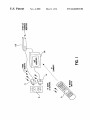
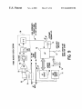
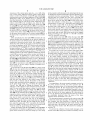
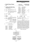
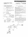
FIG. 1 illustrates an exemplary system for providing a
remote control With appliance poWer aWareness;
operations Will be performed When the macro is executed. In
the example provided, if the television Were already poW
plary remote control of the system of FIG. 1;
ered on prior to executing the macro, executing the macro
might send a poWer toggle command to the television that
Would not have the desired effect of turning the television
on. Rather, to the frustration of a user, the poWer toggle
command in the executing macro Would cause the already
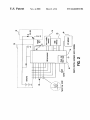
FIG. 2 illustrates a block diagram schematic of an exem
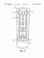
FIG. 3 illustrates a top vieW of the remote control of the
system of FIG. 1;
65
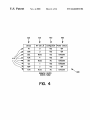
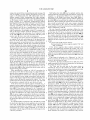
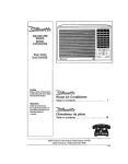
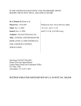
FIG. 4 illustrates an exemplary table in Which poWer state
information is maintained by the remote control of the
system illustrated in FIG. 1;
US 6,642,852 B2
3
4
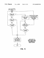
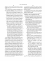
FIG. 5 illustrates an exemplary method for setting up the
table of FIG. 4 to enable the remote control of the system of
FIG. 1 to receive poWer state information;
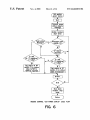
FIG. 6 illustrates an exemplary method for executing an
update of the poWer state information table of FIG. 4;
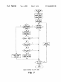
FIG. 7 illustrates an exemplary method for commanding
multiple appliances Within the system of FIG. 1 to be turned
The ROM memory 26 includes executable instructions
that are intended to be executed by the processor 24 to
control the operation of the remote control 10. In this
manner, the processor 24 may be programmed to control the
various electronic components Within the remote control 10,
e.g., to monitor the poWer supply 38, to cause the transmis
sion of signals, etc. MeanWhile, the non-volatile read/Write
memory 34, for example an EEPROM, battery-backed up
RAM, Smart Card, memory stick, or the like, is provided to
to the on state;
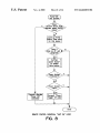
FIG. 8 illustrates an exemplary method for commanding
single appliances Within the system of FIG. 1 to be turned to
10
the on state;
FIG. 9 illustrates a block diagram schematic of an exem
store user entered setup data and parameters as necessary.
While the memory 26 is illustrated and described as a ROM
memory, memory 26 can be comprised of any type of
readable media, such as ROM, RAM, SRAM, FLASH,
plary poWer monitoring unit of the system of FIG. 1;
EEPROM, or the like. Preferably, the memory 26 is non
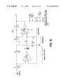
FIG. 10 illustrates a schematic of an exemplary poWer 15 volatile or battery-backed such that data is not required to be
reloaded after battery changes. In addition, the memories 26
monitoring module of the poWer monitoring unit of FIG. 9;
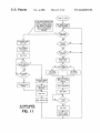
FIG. 11 illustrates an exemplary method for setting up a
and 34 may take the form of a chip, a hard disk, a magnetic
poWer monitoring unit of FIG. 9 and for providing poWer
disk, and/or an optical disk.
For commanding the operation of home appliances of
different makes, models, and types, the memory 26 also
state information to the remote control of the system of FIG.
1;
20
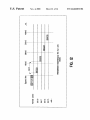
FIG. 12 illustrates an exemplary transmission sequence
betWeen the poWer monitoring units and the remote control
includes a command code library. The command code
of the system of FIG. 1;
may be transmitted from the remote control 10 for the
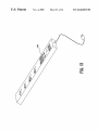
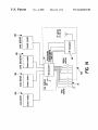
FIG. 13 illustrates a further poWer monitoring unit in the
form of a poWer strip; and
FIG. 14 illustrates a schematic diagram of the exemplary
library is comprised of a plurality of command codes that
purpose of controlling the operation of the home appliances
25
poWer monitoring unit of FIG. 13.
recogniZed by the target home appliance 12. Similarly, the
DETAILED DESCRIPTION
Turning noW to the ?gures, Wherein like reference numer
als refer to like elements, there is illustrated in FIG. 1 a
12. The memory 26 also includes instructions Which the
processor 24 uses in connection With the transmission circuit
32 to cause the command codes to be transmitted in a format
30
memory 26 also includes instructions Which the processor
24 uses in connection With the communications module 40
to cause communications to be transmitted in a format
recogniZed by the poWer monitor units 14.
system for providing a remote control With appliance poWer
aWareness. Generally, the system includes a remote control
To identify home appliances 12 by type and make (and
10 capable of commanding the operation of home appliances
sometimes model) such that the remote control 10 is adapted
to transmit recogniZable command codes in the format
appropriate for such identi?ed home appliances 12, data
12, such as television 12a and set-top box 12b. It Will be
appreciated that the home appliances 12 can be of different
35
may be entered into the remote control 10. Since methods
for setting up a remote control to control the operation of
types (such as, by Way of example only, televisions, VCRs,
DVD players, set-top boxes, ampli?ers, CD players, game
consoles, home lighting, drapery, etc.) manufactured by
different manufacturers. The home appliances 12 receive
40
poWer from an electrical outlet 16 using an intermediate
poWer monitor unit 14 having a socket for receiving the plug
of an appliance 12 and a plug for insertion into a socket of
the electrical outlet 16. As Will be described in greater detail,
the poWer monitor unit 14 bi-directionally communicates
With the remote control 10 to provide the remote control 10
To cause the remote control 10 to perform an action, the
45
remote control 10 is adapted to be responsive to events, such
as a sensed user interaction With one or more keys on the key
With aWareness of the poWer state of a home appliance 12.
In this manner, the remote control 10 can consider the poWer
state of the home appliances When executing a macro or
other commands.
For communicating With the consumer appliances 12 as
Well as the poWer monitor units 14, the remote control 10
preferably includes a processor 24 coupled to a ROM
speci?c home appliances is Well-knoWn, it Will not be
described in greater detail herein. Nevertheless, for addi
tional information pertaining to remote control setup, the
reader may turn to US. Pat. Nos. 5,614,906 and 4,959,810
Which are incorporated herein by reference in their entirety.
matrix 28. More speci?cally, in response to an event appro
priate instructions Within the memory 26 are executed. For
example, When a command key is activated on the remote
50
control 10, the remote control 10 may read the command
code corresponding to the activated command key from
memory 26 and transmit the command code to a home
appliance 12 in a format recogniZable by the home appliance
12. It Will be appreciated that the instructions Within the
memory 26, a key matrix 28 (in the form of physical buttons,
a touch screen, or the like), an internal clock and timer 30, 55 memory 26 can be used not only to cause the transmission
of command codes to home appliances 12 but also to
an IR (or RF) transmission circuit 32 (for sending signals to
perform local operations. While not limiting, local opera
tions that may be performed by the remote control 10
a home appliance 12), an RF (or IR) bi-directional commu
nications module 40 (for sending and receiving signals from
a poWer monitor unit 14), a non-volatile read/Write memory
34, a visible LED 36 (to provide visual feedback to the user
of the remote control 20), and a poWer supply 38 as
illustrated in FIG. 2. As Will be appreciated, the transmission
circuit 32 and communications module 40 perform opera
tions that could be performed by a single device.
Accordingly, the transmission circuit 32 and communica
tions module 40 need not be separate and distinct compo
nents.
include favorite channel setup, macro button setup, com
60
65
mand function key relocation, etc. Since examples of local
operations can be found in US. Pat. Nos. 5,481,256, 5,959,
751, 6,014,092, Which are incorporated herein by reference
in their entirety, they Will not be discussed in greater detail
herein.
By Way of further example, an exemplary remote control
10 is illustrated in FIG. 3. While illustrated as a conventional
hand-held remote control, the remote control can include
US 6,642,852 B2
5
6
other devices such as PDAs, personal computers, or the like.
to cause communications to be transmitted in a format
recogniZed by the remote control 10. In this regard, RF
Accordingly, the description that follows need not be lim
iting. As illustrated, the remote control 10 includes a “Setup”
key 310, a “PoWer” key 320, “Device” keys 330 (for
selecting the mode of operation—i.e., the home appliance/
device to control), “Numeric” keys 340 (corresponding to
transmissions can be made using a custom-designed proto
col operating in one of the frequency bands allocated by
national regulatory agencies for use in control and status
monitoring, or alternatively by a standardiZed conventional
the digits 0—9), and a group of “Macro” keys 370 to Which
protocol such as Bluetooth, etc., using off-the-shelf compo
preprogrammed or user programmable macros can be
nents. The construction and operation of such RF transceiv
ers is Well knoW in the art. Instructions may also be provided
for alloWing the poWer monitor unit 14 to provide status
assigned. Additional, optional keys may include a pair of
keys 350 to command “All On” or “All Off” operations
and/or a pair of keys 360 to command “On” and “Off”
operations for a currently selected device. The operation of
the special keys 350 and 360, Which comprise a smart poWer
feature, Will be described in greater detail in the paragraphs
that folloW. The remaining keys illustrated in FIG. 3 perform
conventional remote control functions that Will be Well
10
information to a consumer by means of, for eXample, one or
more LEDs 70, a display, etc. Once the poWer monitor unit
is initialiZed, the poWer monitor unit enters a loop Wherein
it continually searches for one of at least tWo events, namely,
15
understood by those of ordinary skill in the art.
For monitoring poWer supplied to a home appliance 12
and, accordingly, the state of the home appliance 12 (e.g.,
poWered on or off/in standby mode), the poWer monitoring
unit 12 includes a current sensing device 50 as illustrated in
FIG. 9. The current sensing device 50 may be in the form of
a transformer having a primary Winding 52 Which is inserted
in the path of current ?oW going from the outlet 16 to the
home appliance 12. In this manner, the transformer second
ary Winding 54 Will thus have a current ?oW Which is
25
representative of the current ?oW passing through the trans
former primary Winding 52. In the illustrated current sensing
activation of a user setup sWitch or receipt of a status enquiry
message from the remote control 10.
To con?gure the poWer monitor unit 14 for use in the
system, illustrated in FIG. 11, the poWer monitor unit 14 is
set to recogniZe the “standby/off” and “on” load currents for
the home appliance 12 associated With the poWer monitor
unit 14. To this end, a consumer Would place the appliance
12 to be monitored in the standby state and instruct the
poWer monitor unit 14 to capture a signal representative of
the current How of the home appliance 12 in this standby
state. The instruction to capture a signal representative of the
standby current How of the home appliance 12 can be
entered by activation of a setup sWitch 74. In response to this
instruction, the processor 66 monitors the DC voltage signal
from the conditioning circuitry 58 and stores this voltage
signal as the representation of the standby current ?oW.
device 50, a dropping resistor 56 is inserted as a load to
covert the secondary Winding 54 current to a voltage. It Will
be appreciated that other current sensing devices 50 for
generating a signal representative of the current being draWn
by the home appliance 12 may be used such as, by Way of
eXample only, any Hall Effect device.
To setup the poWer monitor unit 14 to recogniZe the
appliance on current ?oW, a consumer Would place the
appliance 12 to be monitored in the on state and instruct the
poWer monitor unit 14 to capture a representation of the
For conditioning the signal generated by the current 35 resulting current ?oW. The instruction to capture a repre
sentation of the on current How can be entered by, for
sensing device 50, the poWer monitor unit 14 may also be
eXample, a second activation of the setup sWitch 74. In
provided With a signal conditioning circuit 56. For eXample,
the voltage drop across the resistor 56 can be sent though a
response to this instruction, the processor 66 monitors the
signal conditioning circuit 56 comprised of an ampli?er
DC voltage signal from the conditioning circuitry 58 and
recti?er 60/62 and a loW-pass ?lter 64. In this manner, the
AC voltage representation of the AC load current can be
transformed to a DC voltage signal Which can be interfaced
to a processor 66 through an Analog-Digital
converter
stores this voltage signal as the representation of the on
current ?oW. A threshold value may then be determined as
the average of the on and off current ?oW representation
or Voltage to Frequency Oscillator (VFO). Further eXamples
of such circuitry can be seen in “analog-digital CONVER
45
appreciated that the setup procedure can be performed by the
SION HANDBOOK,” Copyright 1972 & 1976 by Analog
Devices, Inc.; Second Edition, June, 1976 and “IC Op-Amp
Cookbook,” by Walter G. Jung; 1974, 1980, and 1986 by
poWer monitor unit prompting the user to place the appli
ance in a given state and automatically monitoring the
resulting current ?oW.
HoWard W. Sams & Co., A Division of Macmillan, Inc.;
Third Edition—Fourth Printing, 1988. pp. 252 and 253,
Which are incorporated herein by reference in their entirety.
For use in establishing an address for the poWer monitor
unit 14, Which address is used to facilitate communications
With the remote control 10, address setting device 76 is
The ampli?er, recti?er and loW pass ?lter are shoWn in
greater detail in FIG. 10.
For poWering the components of the poWer monitor unit
14, a voltage supply 72 is provided. By Way of eXample, the
values. It Will be appreciated that these setup procedures can
be timed to prevent the poWer monitor unit 14 from being
locked in the setup mode of operation. It Will be further
provided and accessible by the processor 66. The address
setting device 76 may include dip sWitches, jumpers, means
55
voltage supply 72 can be circuitry that converts the AC
voltage from the outlet 16 to a voltage level that can directly
poWer the components of the poWer monitor unit 14.
Alternatively, the voltage supply 72 can be batteries. Still
for keying in an address, or the like. In the case of dip
sWitches or jumpers, the address setting device Would be
used to set a bit pattern that Would serve as the address (e. g.,
three sWitches Would alloW the poWer monitor 14 to be set
to one of eight unique addresses). Preferably, the address
further, the poWer monitor unit 14 may include a small
non-volatile memory (such as an EEPROM) to maintain
setting device 76 is accessible to the consumer although the
setting through poWer failures, broWn outs, etc.
eXtra sWitches 76 may be provided in cases Where it is
desired to set a unique system address to alloW multiple
remote controllers 10 to operate independently in the same
address setting device can be factory preset. Additionally,
The processor 66 has associated instructions for accepting
the DC signal supplied from the conditioning circuit 58 and
for performing operations based on the value of the signal.
The processor 66 also has associated instructions Which the
processor 66 uses in connection With an RF (or IR) module
65
vicinity.
During the operation of the system, the poWer monitor
units 14 are used to provide the remote control 10 With
US 6,642,852 B2
7
8
awareness of the current power state (i.e., on or off) of the
one or more home appliances 12 the remote control 10 is
setup to control. The remote control 10 may maintain the
current power state of the home appliances 12 in a table 400,
illustrated in FIG. 4, for further use in a manner to be
in this conteXt is with reference to the initial input by the user
described hereinafter. As illustrated in FIG. 4, the table 400
may maintain data for each device mode supported by the
remote control 10. In the exemplary case, since the illus
trated remote control includes eight device mode keys 330
the table 400 has eight data ?eld rows 410. For each device
mode 420 data may be maintained that is indicative of: 1) an
ID (430) assigned to the power monitor 14 associated with
the device 12 to be controlled in the given device mode; 2)
a status of the device setup (440) within the remote control
for the given device mode; and 3) a power status (450) for
the device 12 as reported by its associated power monitor
unit 14.
to identify the speci?c brand/model of home appliance to be
controlled when the corresponding “Device” button 330 is
activated (See for example US. Pat. Nos. 5,614,906 and
10
device mode is setup. When a data ?eld 440 indicates that a
device mode has not been setup it may be assumed that the
user does not have a home appliance to be controlled in this
15
More speci?cally, the data ?eld (430) maintains the unit
address number that corresponds to the user-set address of
the power monitor unit 14 associated with the device to be
controlled in the given device mode. For example, in the
illustrative table of FIG. 4, the remote control has been setup
to control an appliance in the VCR device mode which has
been indicated to be plugged into a power monitor unit 14
having an address of “3” and to control an appliance in the
TV device mode which has been indicated to be plugged into
a power monitor unit 14 having an address of “0.” It is to be
understood that not all of the appliances 12 that the remote
control 10 may control need a power monitor unit 14 and, in
the case where an appliance in a given device mode is
indicated to be operating without a power monitor unit 14,
the table 400 would maintain an entry of “none.” Preferably
the table 400 is initialiZed when the remote control is ?rst
placed in service such that “none” is maintained in the data
?eld 430 for each device mode 420 until such time as the
device mode is, in fact, setup to indicate an address for a
power monitor unit.
To set the data in the ID data ?eld 430 for a device mode
an “unknown” state. Likewise, if communications with the
25
associated power monitor 14 have failed, the data ?eld 450
again maintains data indicative of an “unknown” state.
To poll the one or more power monitor units 14 to gather
the current power status, he remote control 10 issues a
broadcast status enquiry message, as illustrated in FIG. 6,
via its RF module 40. The power module units 14 respond
to the status enquiry message by transmitting a status
response message having data indicative of the status of the
device associated with the respective power monitor unit 14.
Preferably the status response messages from the one or
more power monitor units 14 are transmitted in an orderly
35
fashion to avoid collisions at the remote control 10. Upon
receiving a status response message from a power monitor
unit 14, received via the RF module 40, the remote control
10 strips the data from the status response message (i.e., the
address of the responding power monitor unit 14 and the
state of the device 12 associated with that power monitor
in FIG. 5. By way of eXample, a user might enter a general
setup mode (e.g., by activating the “Setup” key 310) fol
unit 14) and updates the appropriate status data ?eld 450 in
lowed by an indication to the remote control that the user
the data table 400 to re?ect the received status information.
speci?cally desires to setup the power module unit ID ?eld
In the case where no response is received from a power
45
time the user may indicate to the remote control 10 the
device mode of interest and the ID number of the power
monitor unit associated with the appliance to be controlled
in the given device mode (e.g., by hitting the appropriate
“Device” key 330 and by hitting the numeric key 340
indicative of the address of the associated power monitor
unit). The user could then indicate a desire to eXit the setup
monitor unit 14 or an invalid/untimely response is received,
the power status of the data ?eld corresponding to the
missing or failed power monitor unit 14 is preferably set to
“unknown.”
In responding to the status enquiry message received at
the power monitor unit 14, the power monitor unit 14
measures the power draw of its associated home appliance
as illustrated in FIG. 11. The measured power draw is then
compared to the previously established threshold value. If
mode (e.g., by again hitting the “Setup” key 310) at which
time the indicated ID number would be stored in the data
?eld 430 for the indicated device 420. This process can be
repeated as often as needed to de?ne the ID number of the
power monitor unit for each device mode. This procedure
may also be timed to prevent the remote control 10 from
being locked in a setup mode. By way of an illustrative
eXample, to setup the remote control such that the table 400
illustrated in FIG. 4 results, the user might hit the “Setup”
device mode and, as such, this device mode can be skipped
during processing of an “All On” or “All Off” command
which is described hereinafter.
A still further data ?eld 450 within the data table 400
holds the current power status (i.e., “on” or “off”) of a device
as reported by its associated power monitor unit 14. If a
device is not equipped with a power monitor unit 14 (i.e., the
ID data ?eld 430 has data indicative of “none”) the data ?eld
450 preferably maintains data indicating the appliance is in
420, the user may perform the method generally illustrated
of the table 400 (e.g., by entering a predetermined key
sequence using the numeric keys 340, such as “979”). At this
4,959,810). If no device setup has been performed for a
given device mode the data ?eld 440 for that device main
tains data indicative of this fact, e.g., it maintains data
representative of a state “No.” Preferably, upon initialiZation
of the remote control 10, all of the data ?elds 440 are
provided with a default value of “No” until such time as the
55
the measured power draw is above the established threshold
value, the status of the home appliance 12 is determined to
be “on.” If, however, the measured power draw is not above
the established threshold value, the status of the home
appliance 12 is determined to be “off.”
The determined status is returned to the remote control 10
as data in the status reply message. The status reply message
also includes data that functions to identify the power
data indicative of whether an appliance to be controlled in a
monitor unit 14 transmitting the status reply message. Pref
erably this data is the address of the power monitor unit 14
which the power monitor unit 14 retrieves by reading the
switches 76.
To prevent the collision of status reply messages at the
given device mode has, in fact, been setup by a user. Setup
remote control 10, each power monitor unit 14 may wait an
key, enter the setup code “979,” and active the following
keys: TV-0-AMP-2-VCR-3-CD-1-AUX-4. The setup mode
would be eXited by again hitting the “Setup” key.
Further maintained with the table 400 in data ?eld 440 is
65
US 6,642,852 B2
10
unique time period before transmitting its reply message. By
Way of example, a poWer monitor unit 14 may Wait a time
equal to 20 milliseconds plus 100 milliseconds times its
address number before transmitting the reply message.
Using a pre-transmit delay based on the unit address number
in this manner results in each monitor 14 transmitting its
status response in a sequential, predetermined manner
(starting With unit 0 and ending With unit 7) as illustrated in
FIG. 12. This further provides an additional level of error
checking capability to the receiving remote control since
each monitor unit 14 has a predetermined time WindoW
during Which the remote control may expect to receive a
10
basis as illustrated in FIG. 8.
By Way of speci?c example, assuming a Macro key Was
reply transmission. Accordingly, receipt of a message out
side of this time WindoW Would be indicative of an error
condition resulting in the indication of an “unknown” state
in the table 400 for the device associated With the poWer
monitor unit 14 that is late With its transmission.
The polling of the poWer monitor units 14 may be initiated
in response to the user activating one of the special poWer
keys, one of the macro keys, in response to activation of a
programmed to turn the VCR device on, turn the TV device
on, and tune the TV device to channel 3, activation of the
15
setup):
For each of the VCR and TV devices:
25
It is determined if the device supports explicit “On” and
“Off” commands.
If the device supports these explicit commands, the
remote control 10 merely transmits the explicit “On” com
mand for the device and the macro continues to the next step.
If the device does not support explicit commands (i.e., it
supports a poWer toggle command), the current status of the
device is retrieved from the poWer status ?eld 450 of the data
table 400.
(i.e., a poWer status monitor address Was setup in the remote
control and the poWer status monitor has reported a current
If the status is indicated to be “Unknown” or “On,” no
status) to enter the “On” state. In this regard, the transmis
sion of the appropriate command signals to the appliances
12 (if necessary) may be performed in a sequential order
folloWing the order in Which the devices are maintained
Within the table 400. Within this sequential order, if a device
mode has not been setup by the user (indicated by a “no” in
the data ?eld 440 for that device) this device mode Will be
Macro key Would result in the updating of the table 400 (in
the manner described above) and the processing of the
macro command steps as folloWs (assuming the table 400
indicates that the VCR and TV devices Were setup and the
addresses of their respective poWer monitor units Were also
given setup mode, at timed intervals, etc. Without limitation
For example, When the “All On” key is activated, the remote
control transmits the status enquiry message and retrieves
the poWer status of the devices from the poWer monitor units
14 as described above. Once the table 400 has been updated
With the status of the devices, as illustrated in FIG. 7, the
remote control 10 performs processing to command each
device that has been identi?ed to the remote control (i.e.,
setup) and Which has a functioning poWer monitor unit 14
Still further, the table 400 can be updated and the data
contained therein considered in the performance of the steps
assigned to a programmed Macro key or in response to
activation of the single unit poWer keys 360. Again, a
transmission of a status enquiry message and the updating of
the table 400 can be performed in response to activation of
these keys. The processing in response to activation of these
keys Would be performed in the same manner described
above With respect to the “All On”/“All Off” procedures
excepting that it Would be performed on an individual device
35
further processing for the device is performed and the macro
moves to the next step (if any).
If, hoWever, the status is indicated to be “Off,” the poWer
toggle command for the device is transmitted for the purpose
of causing the device to enter the
“On” state and the next step in the macro chain is
executed (if any). In this manner, the remote control 10
skipped during the procedure.
ensures that execution of a macro or the single poWer on key
More speci?cally, to initiate an “All On” procedure, for
each device mode that has been setup, it is determined if a
Will not place an appliance in an undesired state.
speci?c device supports explicit “On” and “Off” commands.
This is determined by reference the command code library
for the speci?ed device using conventional look-up tech
niques. If the device supports these explicit commands, the
While speci?c embodiments of the present invention have
been described in detail, it Will be appreciated by those
skilled in the art that various modi?cations and alternatives
to those details could be developed in light of the overall
45
teachings of the disclosure. For example, it is contemplated
remote control 10 merely transmits the explicit “On” com
mand for that device to place the device in the “On” state and
that several current monitor modules 990 may be combined
With a single microprocessor and RF transceiver 980 into a
the procedure continues With the next device (if any).
If the device does not support explicit commands (i.e., it
smart poWer strip 900 for use in an entertainment center, as
supports a poWer toggle command), the current status of the
device is retrieved from the poWer status ?eld 450 of the data
operation and the processing logic is essentially the same as
described previously excepting that, in this case, upon
table 400. If the status is indicated to be “Unknown” or
receipt of a poWer status query from the remote control 10
“On,” no further processing for this device is performed and
the procedure moves to the next device (if any). If, hoWever,
the microprocessor 66 Will poll each poWer outlet and
transmit a corresponding number of sequential status reply
illustrated in FIGS. 13 and 14. In this case, the method of
the status is indicated to be “Off” in the poWer status ?eld 55 messages to the remote control 10. Each poWer outlet in the
strip 900 can be assigned a unique address by the user or the
ted for the purpose of causing the device to enter the “On”
user can set one number for the poWer strip Which causes the
state. In this manner, activation of the “All On” key avoids
outlets to be automatically assigned sequential addresses
the inadvertent placing of a home appliance in an unWanted
starting With the user set number. This approach alloWs
“Off” state.
poWer strips 900 and individual monitor modules 14 to be
450, the poWer toggle command for that device is transmit
In a similar fashion, activation of the “All Of’ key avoids
the inadvertent placing of a home appliance in an unWanted
“On” state. In this regard, activation of the “All Of’ key
causes the transmission of an explicit “Off” command, the
transmission of a poWer toggle command, or no action in
accordance With the logic set forth above With respect to the
“All On” procedure.
65
intermixed transparently to the remote control logic. Still
further, it Will be appreciated that a single poWer monitor
module 990 could be sWitched betWeen multiple poWer
outlets using triacs or similar poWer sWitching apparatus
under control of the microprocessor 66. Accordingly, it Will
be understood that the particular arrangements and proce
dures disclosed are meant to be illustrative only and not