1
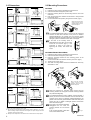
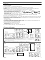
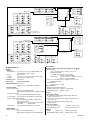
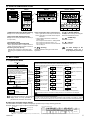
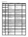
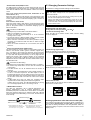
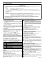
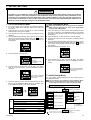
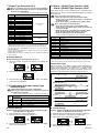
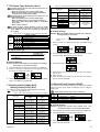
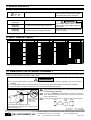
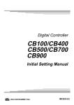
Digital Controller CB100/CB400/CB500/CB700/CB900 1. PRODUCT CHECK INSTRUCTION MANUAL CB100 CB400 CB500 CB700 (1) (2) CB900 IMCB25-E3 Thank you for purchasing the RKC instrument. In order to achieve maximum performance and ensure proper operation of your new instrument, carefully read all the instructions in this manual. Please place this manual in a convenient location for easy reference. NOTICE • This manual assumes that the reader has a fundamental knowledge of the principles of electricity, process control, computer technology and communications. • The figures, diagrams and numeric values used in this manual are only for purpose of illustration. • RKC is not responsible for any damage or injury that is caused as a result of using this instrument, instrument failure or indirect damage. • Periodic maintenance is required for safe and proper operation of this instrument. Some components have a limited service life, or characteristics that change over time. • Every effort has been made to ensure accuracy of all information contained herein. RKC makes no warranty expressed or implied, with respect to the accuracy of the information. The information in this manual is subject to change without prior notice. • No portion of this document may be reprinted, modified, copied, transmitted, digitized, stored, processed or retrieved through any mechanical, electronic, optical or other means without prior written approval from RKC. All Rights Reserved, Copyright 1998, RKC INSTRUMENT INC. ® (4) (5) * (6) (7) - / /Y (8) (9) (10) F: PID action with autotuning (Reverse action) D: PID action with autotuning (Direct action) 1 W: Heat/cool PID action with autotuning (Water cooling) 1 A : Heat/cool PID action with autotuning (Air cooling) (2) Input type, (3) Range code: See “9. INPUT RANGE TABLE.” (4) First control output [OUT1] (Heat-side) M: Relay contact T: Triac 8: Current (4 to 20 mA DC) V: Voltage pulse G: Trigger (for triac driving) (5) Second control output [OUT2] (Cool-side) No symbol: When control action is F or D. M: Relay contact T: Triac V: Voltage pulse 8: Current (4 to 20 mA DC) (6) Alarm 1 [ALM1], (7) Alarm 2 [ALM2] N: A: B: C: D: E: No alarm H: Process high alarm Deviation high alarm J: Process low alarm Deviation low alarm K: Process high alarm with hold action Deviation high/low alarm L: Process low alarm with hold action 2 Band alarm P: Heater break alarm (CTL-6) 2 ( ) Deviation high alarm S: Heater break alarm CTL-12 3 with hold action R: Control loop break alarm F: Deviation low alarm V: SV high alarm with hold action W: SV low alarm G: Deviation high/low alarm with hold action CAUTION • This is a Class A instrument. In a domestic environment, this instrument may cause radio interference, in which case the user may be required to take adequate measures. • This instrument is protected from electric shock by reinforced insulation. Provide reinforced insulation between the wire for the input signal and the wires for instrument power supply, source of power and loads. • Be sure to provide an appropriate surge control circuit respectively for the following: - If input/output or signal lines within the building are longer than 30 meters. - If input/output or signal lines leave the building, regardless the length. • This instrument is designed for installation in an enclosed instrumentation panel. All high-voltage connections such as power supply terminals must be enclosed in the instrumentation panel to avoid electric shock by operating personnel. • All precautions described in this manual should be taken to avoid damage to the instrument or equipment. • All wiring must be in accordance with local codes and regulations. • All wiring must be completed before power is turned on to prevent electric shock, instrument failure, or incorrect action. The power must be turned off before repairing work for input break and output failure including replacement of sensor, contactor or SSR, and all wiring must be completed before power is turned on again. • To prevent instrument damage of failure, protect the power line and the input/output lines from high currents with a protection device such as fuse, circuit breaker, etc. • Prevent metal fragments or lead wire scraps from falling inside instrument case to avoid electric shock, fire or malfunction. • Tighten each terminal screw to the specified torque found in the manual to avoid electric shock, fire or malfunction. • For proper operation of this instrument, provide adequate ventilation for heat dispensation. • Do not connect wires to unused terminals as this will interfere with proper operation of the instrument. • Turn off the power supply before cleaning the instrument. • Do not use a volatile solvent such as paint thinner to clean the instrument. Deformation or discoloration will occur. Use a soft, dry cloth to remove stains from the instrument. • To avoid damage to instrument display, do not rub with an abrasive material or push front panel with a hard object. • Do not connect modular connectors to telephone line. - (1) Control action WARNING • An external protection device must be installed if failure of this instrument could result in damage to the instrument, equipment or injury to personnel. • All wiring must be completed before power is turned on to prevent electric shock, fire or damage to instrument and equipment. • This instrument must be used in accordance with the specifications to prevent fire or damage to instrument and equipment. • This instrument is not intended for use in locations subject to flammable or explosive gases. • Do not touch high-voltage connections such as power supply terminals, etc. to avoid electric shock. • RKC is not responsible if this instrument is repaired, modified or disassembled by other than factory-approved personnel. Malfunction can occur and warranty is void under these conditions. (3) (8) Communication function N: No communication function 5: RS-485 (2-wire system) (9) Waterproof/dustproof N: No waterproof/dustproof 1: Waterproof/dustproof (10) Case color N: White 1 2 3 A: Black No self-tuning function is provided in the W or A control action type. Heater break alarm cannot be specified in case of ALM1. Also, it isn’t possible to specify when control output is current output. As control loop break alarm, only either the ALM1 or ALM2 is selected. Check that power supply voltage is also the same as that specified when ordering. <Accessories> Mounting frame (CB100): 1 Mounting brackets (CB400/CB500/CB700/CB900): 2 * Instruction manual (IMCB25-E3): 1 *CB900 waterproof/dustproof option: 4 pieces 2. MOUNTING 2.1 Mounting Cautions (1) This instrument is intended to be used under the following environmental conditions. (IEC61010-1) [OVERVOLTAGE CATEGORY II, POLLUTION DEGREE 2] (2) Use this instrument within the following ambient temperature and ambient humidity. • Allowable ambient temperature: 0 to 50 °C • Allowable ambient humidity: 5 to 95 % RH 3 (Absolute humidity: MAX. W. C 29 g/m dry air at 101.3 kPa) (3) Avoid the following when selecting the mounting location. • Rapid changes in ambient temperature which may cause condensation. • Corrosive or inflammable gases. • Direct vibration or shock to the mainframe. • Water, oil, chemicals, vapor or steam splashes. • Excessive dust, salt or iron particles. • Excessive induction noise, static electricity, magnetic fields or noise. • Direct air flow from an air conditioner. • Exposure to direct sunlight. • Excessive heat accumulation. RKC INSTRUMENT INC. 2.2 Dimensions 2.3 Mounting Procedures Individual mounting 45 0 +0.6 25 45 0 9.2 25 25 48 1. Prepare the panel cutout as specified in 2.2 Dimensions. 2. Insert the instrument through the panel cutout. 3. Insert the mounting frame into the mounting from the rear of the instrument. 4. Push the mounting frame forward until the frame is firmly secured to the panel. (Fig.1) 5. Fix the instrument to the panel by using the two screws. (Fig.2) +0.6 44.8 (Unit: mm) CB100 25 CB100 61.6 +0.6 L1 0 1* ( 45 0 +0.6 48 44.8 Close horizontal mounting 1) 8.2 L1=(48×n-3) n:Number of controllers (2 ≦n≦6) 100 Mounting frame Individual mounting CB400 +0.8 0 Fig.1 Close horizontal mounting 110.8 +0.6 L1 0 92 0 +0.8 96 91.8 30 92 9.2 48 Screw +0.6 0 25 45 44.8 (Unit: mm) 1(* 1) 8.2 L1=(48 ×n-3) n:Number of controllers (2≦n≦6) 100 9.2 CB500 Individual mounting +0.8 0 30 When using the mounting screws, only turn one full revolution after the screw touches the panel. 92 The waterproof/dustproof option on the front of the instrument conforms to IP66 when mounted on the panel. For effective waterproof/dustproof, the gasket must be securely placed between instrument and panel without any gap. If the gasket is damaged, please contact RKC sales office or the agent. If the hook in the mounting frame is disengaged from the case, the mounting frame can be removed (Fig.3). If the instrument is fixed to the panel by tightening the screws, first loosen the screw. Fig. 3 25 45 110.8 91.8 +0.6 0 (Unit: mm) Fig.2 Close vertical mounting 8.2 92+0.8 0 100 L1 48 44.8 +0.6 0 96 1(* 1) L1=(48 ×n-3) n:Number of controllers (2≦n≦6) CB400/CB500/CB700/CB900 1. Prepare the panel cutout as specified in 2.2 Dimensions. 2. Insert the instrument through the panel cutout. 3. Insert the mounting bracket into the mounting groove of the instrument. (Fig.1) 4. Pull till click sounds to the direction shown by the arrow. (Fig.2) 5. Tighten up the screw. (Fig.3) 6. The other mounting bracket should be installed the same way described in 3. to 5. Mounting bracket Individual mounting CB700 68 +0.7 0 67.8 25 +0.7 68 0 (Unit: mm) 9.2 Close horizontal mounting Fig.2 Fig.1 +0.7 L1 0 When using the mounting screws, only turn one full revolution after the screw touches the panel. 68 0 +0.7 86.8 72 67.8 30 72 1(* 1) L1=(72 ×n-4) n:Number of controllers (2≦n≦6) 100 8.2 *2 92 +0.8 0 When the instrument is mounted, always secure with two mounting brackets so that upper and lower mounting brackets are positioned diagonally. +0.8 92 0 91.8 25 (Unit: mm) 9.2 91.8 Close horizontal mounting +0.8 L1 0 92 0 +0.8 96 110.8 30 96 Fig. 3 Individual mounting CB900 1(* 1) 8.2 100 L1=(96 ×n-4) n: Number of controllers (2≦n≦6) *1 Rubber (option) *2 Up to four mounting brackets can be used. For mounting of the instrument, panel thickness must be between 1 to 10 mm. (When mounting multiple instruments close together, the panel strength should be checked to ensure proper support.) Waterproof and dustproof are not effective when instruments are closely spaced. 2 The waterproof/dustproof option (CB900: mounting bracket 4 pieces) on the front of the instrument conforms to IP65 when mounted on the panel. For effective waterproof/dustproof, the gasket must be securely placed between instrument and panel without any gap. If gasket is damaged, please contact RKC sales office or the agent. If the hook in the mounting bracket is disengaged from the case, the mounting bracket can be removed (Fig. 4). If the mounting bracket is fixed with screw, loosen these screws. Fig. 4 IMCB25-E3 3. WIRING 3.1 Wiring Cautions • For thermocouple input, use the appropriate compensation wire. • For RTD input, use low resistance lead wire with no difference in resistance between the three lead wires. • To avoid noise induction, keep input signal wire away from instrument power line, load lines and power lines of other electric equipment. • If there is electrical noise in the vicinity of the instrument that could affect operation, use a noise filter. - Shorten the distance between the twisted power supply wire Instrument power Twist these leadwires pitches to achieve the most effective noise reduction. Instrument IN OUT - Always install the noise filter on a grounded panel. Minimize power Noise filter terminals the wiring distance between the noise filter output and the Shorten distance between Minimize pitches instrument power supply terminals to achieve the most distance effective noise reduction. - Do not connect fuses or switches to the noise filter output wiring as this will reduce the effectiveness of the noise filter. • Power supply wiring must be twisted and have a low voltage drop. • About four seconds are required as preparation time for contact output every time the instrument is turned on. Use a delay relay when the output line, is used for an external interlock circuit. • This instrument is not furnished with a power supply switch or fuses. Therefore, if a fuse or power supply switch is required, install close to the instrument. - Fuse type: Time-lag fuse - Recommended fuse rating: Rated voltage 250 V Rated current: 1 A • For the current input specification, a resistor of 250 Ω (±0.02 % ±10 ppm, 0.25 W or more) must be connected between the input terminals. This resistor must be provided by the customer. • Use the solderless terminal appropriate to the screw size. - Screw size: M3 x 6 - Recommended tightening torque: 0.4 N m [4 kgf cm] • For an instrument with 24 V power supply, supply power from a SELV circuit. 3.2 Terminal Configuration Power supply CB100 AC L N OUT1 T1 OUT1 4 5 Voltage pulse Relay contact Current 3 2 N OUT1 + 5 4 − 6 F, D action types OUT1 5 5 Triac out NO NC 6 + + 5 NO Alarm 1 Communication 4 8 ALM1 9 CT input 5 RS-485 T/R(A) 6 T/R(B) RTD input 10 Current transformer input 13 SG OUT1 RTD 12 18 (Option) (Option) + 11 B TC CT1 15 TC input A 11 17 14 NO − 6 W, A action types 7 ALM2 Input 3 OUT1 6 NO Alarm 2 (Option) NO 4 Alarm output 7 8 9 10 11 12 OUT2 3 − 13 14 15 16 17 18 Relay contact OUT2 Triac out 4 OUT1 6 G 2 Voltage pulse Current OUT2 Triac out 5 1 2 3 4 5 6 1 100 to 240V − Triac Triac 4 2 L Control output NO: Normally open NC: Normally closed T2 AC 1 24V 24V Trigger + DC 1 * Cautions for Communication terminal wiring: Conduct wiring so that the power supply terminals (screw heads) do not touch the communication terminal lugs. Especially when two lugs are connected to one communication terminal for the use of multidrop connection, much care should be exercised not to touch the power supply terminals with the lugs. 12 − B Current input Voltage input 0 to 20 mA DC 4 to 20 mA DC 0 to 5 V DC 1 to 5 V DC 11 + + 11 IN 12 − 12 − It is recommended that the host computer communication line be isolated from the power supply and earth. Power supply CB400 AC L DC 1 24V + 1 24V N 2 AC L Communication 1 100 to 240V − 2 N 2 Control output NO: Normally open NC: Normally closed Trigger T2 T1 OUT2 Triac 4 OUT1 5 OUT1 4 Triac out 5 Voltage pulse Current + Relay contact 6 5 − 6 F, D action types 3 4 OUT1 5 5 Triac out NO NC 6 The terminal arrangement of CB500 is as shown in the following diagram, but the terminal configuration of CB500 is the same as that of CB400. + Relay contact 4 + 5 Alarm 2 4 OUT1 OUT1 6 3 NO − − 6 W, A action types Alarm output OUT2 3 OUT2 Triac out 4 OUT1 OUT1 G Voltage pulse Current Triac 5 Alarm 1 NO NO 7 ALM2 8 ALM1 9 13 14 15 16 5 6 7 8 17 18 19 20 9 10 11 12 21 22 23 24 RS-485 T/R(A) 14 T/R(B) 15 (Option) CT input Current transformer input 23 CT1 24 6 13 14 15 16 17 18 19 20 21 22 23 24 13 SG (Option) NO (Option) Input RTD input 10 TC input A RTD 1 2 3 4 5 6 7 8 9 10 11 12 11 B 11 + Current input Voltage input 0 to 20 mA DC 4 to 20 mA DC 0 to 5 V DC 1 to 5 V DC 11 + B 12 − 11 + IN TC 12 IMCB25-E3 1 2 3 4 12 − 12 − 3 Power supply CB700 AC L 24V Triac OUT2 3 4 OUT1 5 Triac out Triac OUT1 4 OUT1 T1 5 G 6 4 Triac out 5 + 5 − 2 OUT1 5 NO − 6 W, A action types Voltage pulse Current 6 T/R(B) 9 10 11 12 13 14 15 16 17 18 12 CT input Current transformer input CT1 15 (Option) Input RTD input 16 17 6 0 to 20 mA DC 4 to 20 mA DC RTD NO Current input TC input A 5 NC 3 B 17 + 17 L 18 4 OUT1 5 Triac out Triac 4 OUT1 + 3 3 OUT1 4 Triac out 4 OUT1 5 5 5 NO − 6 W, A action types + Relay contact 4 5 Alarm 2 Alarm 1 B + NO 18 − NO 7 8 ALM1 RTD input TC input A RTD B 11 + B 12 − K, J, R, S, B, E, T, N, PLII, W5Re/W26Re, U, L Input impedance: Approx. 1 MΩ Pt100, JPt100 0 to 5 V DC, 1 to 5 V DC, 0 to 10 V DC (Z-1010) 0 to 20 mA DC, 4 to 20 mA DC 0.5 seconds See Input range table Control method: PID control ON/OFF, P, PI, or PD actions is available Control output: Relay contact output: 250 V AC, 3A (Resistive load) Electrical life: 300,000 times or more (Rated load) Voltage pulse output: 0/12 V DC (Load resistance 600 Ω or more) 4 to 20 mA DC (Load resistance 600 Ω or less) Trigger output (for triac driving): Zero cross method for medium capacity triac driving (100 A or less) Load voltage used: 100 V AC line, 200 V AC line Load used: Resistive load Triac output: NO: Normally open NC: Normally closed Current input Voltage input 0 to 20 mA DC 4 to 20 mA DC 0 to 5 V DC 1 to 5 V DC 11 + SG 13 RS-485 T/R(A) 14 T/R(B) 15 (Option) CT input Current transformer input 23 0.5 A (Ambient temperature: 40 °C or less) Alarm output: Relay contact output: 250 V AC, 1A (Resistive load) Electrical life: 50,000 times or more (Rated load) 11 24 (Option) + IN TC 12 18 − CT1 6 Input range: 13 14 15 16 17 18 19 20 21 22 23 24 Input 11 NO NC Sampling cycle: Current output: 2 ALM2 Specifications Input: RTD: Voltage: Current: N + 17 IN 18 − 1 2 3 4 5 6 7 8 9 10 11 12 100 to 240V (Option) 10 0 to 5 V DC 1 to 5 V DC Communication 1 9 5 OUT1 Input type: Thermocouple: L − 2 6 OUT1 − 6 F, D action types 2 AC Alarm output NO 4 Voltage pulse Current 1 OUT2 OUT1 6 Trigger − + DC 1 24V N Voltage input TC NO: Normally open NC: Normally closed Relay contact OUT2 Triac out 11 ALM1 (Option) Power supply + NO Alarm 1 10 ALM2 14 4 5 Voltage pulse Current NO Alarm 2 (Option) AC OUT2 4 8 OUT1 − 6 F, D action types Triac 6 RS-485 T/R(A) Relay contact Control output G 7 SG 24V 5 2 N Communication 4 CB900 T1 1 2 3 4 5 6 7 8 9 3 OUT1 T2 Alarm output 1 100 to 240V NO 4 L OUT2 3 − + 2 AC Relay contact OUT1 6 T2 + OUT2 Triac out Trigger Voltage pulse Current 1 24V N Control output + DC 1 12 − 12 − Performance: Display accuracy (at the ambient temperature 23 °C ± 2 °C): Thermocouple: ± (0.3 % of display value + 1 digit) or ± 2 °C [4 °F] Whichever is greater R, S and B input: 0 to 399 °C [0 to 799 °F] Accuracy is not guaranteed. T and U input: −199.9 to −100.0 °C [−199.9 to −158.0 °F] Accuracy is not guaranteed. RTD: ± (0.3 % of display value + 1 digit) or ± 0.8 °C [1.6 °F] Whichever is greater Voltage/Current: ± (0.3 % of span + 1 digit) Memory backup: Backed up by Nonvolatile Memory Number of write times: Approx. 1,000,000 times Data storage period: Approx. 10 years Power: Power supply voltage: 85 to 264 V AC (Power supply voltage range), 50/60 Hz Rating: 100 to 240 V AC 21.6 to 26.4 V AC (Power supply voltage range), 50/60 Hz Rating: 24 V AC 21.6 to 26.4 V DC (Power supply voltage range) Rating: 24 V DC Power consumption: 7 VA max. (at 100 V AC) 5 VA max. (at 24 V AC) 10 VA max. (at 240 V AC) 160 mA max. (at 24 V DC) Weight: CB100: Approx. 170 g CB400/CB500: Approx. 250 g CB700: Approx. 290 g CB900: Approx. 340 g IMCB25-E3 4. PARTS DESCRIPTION CB400 CB100 PV (1) AT OUT1 OUT2 ALM1 ALM2 PV CB700, CB900 SV (2) (1) AT (3) SV SET (2) R/S SET RKC (1) PV (2) SV CB500 (4) (5) (6) (7) OUT1 OUT2 ALM1 SET ALM2 OUT2 ALM1 (3) (4) (1) (3) ALM2 R/S SV RKC CB500 CB100 AT OUT1 PV (5) (6) (2) (7) AT R/S OUT1 SET RKC CB400 OUT2 ALM1 ALM2 (3) R/S RKC CB900 (4) (4) (5) (6) (7) (1) Measured value (PV) display [Green] Displays PV or various parameter symbols. (2) Set value (SV) display [Orange] Displays SV or various parameter set values (or CT input value). (3) Indication lamps Alarm output lamps (ALM1,ALM2) [Red] ALM1: Lights when alarm 1 output is turned on. ALM2: Lights when alarm 2 output is turned on. Autotuning (AT) lamp [Green] Flashes when autotuning is activated. (After autotuning is completed: AT lamp will become OFF) (5) (6) (7) Control output lamps (OUT1, OUT2) [Green] (5) R / S (Shift & R/S key) OUT1: Lights when control output is turned on.* Shift digits when settings are changed. Select the RUN/STOP function. OUT2: Lights when cool-side control output is turned on.* (4) (DOWN key) (6) * Lamp indication becomes as follows for current output. For an output of less than 0 %: Extinguished For an output of more than 100 %: Lit For an output of more than 0 % but less than 100 %: Dimly lit. Decrease numerals. (UP key) (7) Increase numerals. (Set key) SET To avoid damage to the instrument, never use a sharp object to press keys. Used for parameter calling up and set value registration. 5. SETTING 5.1 Operation Menu Power ON Parameter Setting Mode This mode is used to set the parameters such as alarms, PID constants, etc. (See page 6.) The following parameter symbols are displayed as the SET key is pressed. Input type and Input range Display Automatically (in 4 sec) PV/SV Display Mode (CT1) The controller will display the measured Press the SET key value (PV) and the set value (SV). The controller can be switched to RUN or for 2 seconds. STOP mode (Factory set value: RUN). PV SV PV/SV monitor (RUN mode) Press the <R/S key for 1 second. SV STOP character display (STOP mode) Press the <R/S key while pressing the SET key. Press the SET key Current transformer (CT) input value 1 monitor SET key Alarm 1 set value (ALM1) (AL1) (AL2) PV SV SET key SET key PV bias Derivative time (Pb) (D) SET key (Ar) SET key SET key Anti-reset windup Set data lock (LCK) SET key SET key Return to the first parameter SV setting Factory set value: Cool-side proportioning cycle (t) (I) LBA deadband (Lbd) SET key Integral time SET key This is the mode used to set the SV. Deadband (db) (P) SET key SV Setting Mode SET key Proportional band SET key Control loop break alarm (LBA) time Cool-side proportioning band (Pc) (STU) SET key Heater break alarm (HBA) 1 set value (LbA) SET key Self-tuning (ST) SET key (HbA1) (T) SET key SET key Alarm 2 set value (ALM2) Heat-side proportioning cycle Autotuning (AT) (ATU) Parameters which are not related to existing functions on the controller are not displayed. 0 °C [°F] or 0.0 °C [°F] This instrument returns to the PV/SV display mode if no key operation is performed for more than one minute. Communication Setting Mode This mode is used to set the communication parameters when specified. For details on protocol, identifiers and communication setting mode, see the Communication Instruction Manual (IMCB03-E ). Input type and input range display This instrument immediately confirms the input type symbol and input range following power ON. Example: When sensor type of input is K thermocouple. * Input Type Symbol Table Symbol PV SV Automatically PV Input range high SV Input range low Input type symbol * Unit for input and SV display (Celsius: °C, Fahrenheit: °F, Voltage/current input: no character shown) IMCB25-E3 Symbol RTD Thermocouple (TC) Input type K J R S B E T N PL II (∗) W5Re/ W26Re U L JPt 100 Pt 100 Voltage (Current) (∗) (∗): This input type is not displayed in the Z-1021 specification. 5 5.2 Parameter List Parameter symbols which are not related to existing functions on the controller are not displayed. Symbol Name Setting range Description Temperature input: Deviation alarm, Process alarm, SV alarm: −1999 to +9999 °C [°F] or −199.9 to +999.9 ° C [°F] Voltage/current inputs: Deviation alarm: −span to +span (Within 9999) Process alarm, SV alarm: Same as input range Set the alarm 1 set value and alarm 2 set Temperature input: 50 (50.0) value. Heater break alarm (HBA) 1 set value 1 0.0 to 100.0 A Alarm value is set by referring to input value from the current transformer (CT). Used only for single-phase. 0.0 Control loop break alarm (LBA) time 2 0.1 to 200.0 minutes Set control loop break alarm set value. 8.0 LBA deadband 3 Temperature input: 0 to 9999 °C [°F] Voltage/current inputs: 0 to 100 % of span Set the area of not outputting LBA. No LBA deadband functions with 0 set. Differential gap : Temperature input: 0.8 °C [°F ] Voltage/current inputs: 0.8 % of span 0 Autotuning (AT) 0: AT end or cancel 1: AT start or execution Turns the autotuning ON/OFF. 0 Self-tuning (ST) 0: Self-tuning OFF 1: Self-tuning ON Turns the self-tuning ON/OFF. 0 Proportional band Temperature input: 1 (0.1) to span or 9999 (999.9) °C [°F] Voltage/current inputs: 0.1 to 100.0 % of span Set when PI, PD or PID control is performed. Temperature input: Heat/cool PID action: Proportional band 30 (30.0) setting on the heat-side. Voltage/current inputs: ON/OFF action control when set to 0 (0.0). 3.0 ON/OFF action differential gap: Temperature input: 2 (0.2) °C [°F ] Voltage/current inputs: 0.2 % of span Integral time 1 to 3600 seconds (0 second: PD action) Set the time of integral action to eliminate the offset occurring in proportional control. 240 Derivative time 1 to 3600 seconds (0 second: PI action) Set the time of derivative action to improve control stability by preparing for output changes. 60 Anti-reset windup (ARW) 1 to 100 % of heat-side proportional Overshooting and undershooting are band restricted by the integral effect. (0 %: Integral action OFF) Heat-side proportioning cycle 1 to 100 seconds (Not displayed if the control output is current output.) Cool-side proportional band Deadband 1 to 1000 % of heat-side proportional Set cool-side proportional band. heat/cool PID action. Alarm 1 set value (ALM1) Alarm 2 set value (ALM2) See *1. Cool-side proportioning cycle PV bias Set data lock (LCK) For the alarm action type, see page 10 Voltage/ current inputs: and 11. 5.0 Alarm differential gap: Temperature input: 2 or 2.0 °C [°F] Voltage/current inputs: 0.2% of span See *2. See *3. 6 Factory set value Display input value from the current transformer. [Displayed only when the instrument has the heater break alarm ] Current transformer 0.0 to 100.0 A [Display only] (CT) input value 1 monitor Temperature input: −10 to +10 °C [°F] or −10.0 to +10.0 °C [°F] Voltage/current inputs: −10.0 to +10.0 % of span 100 Set control output cycle. Heat/cool PID action: Heat-side proportioning cycle Relay contact output: 20 Voltage pulse output/ Trigger output for triac driving/Triac output: 2 band when Set control action deadband between heat-side and cool-side proportional bands. Minus (−) setting results in overlap. 100 0 or 0.0 1 to 100 seconds Set control cool-side output cycle for Relay contact output: 20 (Not displayed if the control output is heat/cool PID action. Voltage pulse output/ Triac output: 2 current output.) Temperature input: 0 or 0.0 Sensor correction is made by adding bias −1999 to +9999 °C [°F] or value to measured value (PV). −199.9 to +999.9 °C [°F] Voltage/current inputs: −span to +span Performs set data change enable/disable. 0000 Parameters other than SV and Alarms 0: Unlock 1: Lock Alarms 0: Unlock 1: Lock SV 0: Unlock 1: Lock Initialization mode 0: Lock 1: Unlock IMCB25-E3 1 Heater Break Alarm (HBA) function The HBA function monitors the current flowing through the load by a dedicated current transformer (CT), compares the measured value with the HBA set value, and detects a fault in the heating circuit. Low or No current flow (Heater break, malfunction of the control device, etc.): When the control output is ON and the current transformer input value is equal to or less than the heater break determination point for the preset number of consecutive sampling cycle, an alarm is activated. Over current or short-circuit: When the control output is OFF and the current transformer input value is equal to or greater than the heater break determination point for the preset number of consecutive sampling cycle, an alarm is activated. 5.3 Changing Parameter Settings Procedures to change parameter settings are shown below. To store a new value for the parameter, always press the SET key. The display changes to the next parameter and the new value will be stored. − A new value will not be stored without pressing SET key after the new value is displayed on the display. − After a new value has been displayed by using the UP and DOWN keys, the SET key must be pressed within one minute, or the new value is not stored and the display will return to the PV/SV monitor screen. Change the set value (SV) Change the set value (SV) from 0 °C to 200 °C Precaution for HBA setting: • Displayed only for when HBA is selected as Alarm 2. • HBA is not available on a current output. • Set the set value to approximately 85 % of the maximum reading of the CT input. • Set the set value to a slightly smaller value to prevent a false alarm if the power supply may become unstable. • When more than one heater is connected in parallel, it may be necessary to increase the HBA set value to detect a single heater failure. • When the current transformer is not connected, the HBA is turned on. 1. Select the SV setting mode Press the SET key at PV/SV monitor screen until SV setting screen is displayed. PV PV SV SV AT OUT1 SET OUT2 ALM1 ALM2 R/S AT PV/SV monitor display (PV/SV display mode) ALM1 ALM2 SV setting display (SV setting mode) 2. Shift the high-lighted digit Press the <R/S key to high-light the hundreds digit. The high-lighted digit indicates which digit can be set. PV PV SV SV AT OUT1 SET Precaution for LBA setting: • Displayed only for when LBA is selected as Alarm 1 or Alarm 2. • No control loop break alarm can be used at heat/cool PID control action. • The LBA function can not be activated when AT function is turned on. • The LBA function is activated when control output reaches 0 % or 100 %. The time required for the LBA output to turn on includes both the time from the initial occurrence of loop failure and the LBA setting time. Recommended setting for LBA is for the set value of the LBA to be twice the value of the integral time (I). • If LBA setting time does not match the controlled object requirements, the LBA selling time should be lengthened. If setting time is not correct, the LBA will malfunction by turning on or off at inappropriate times or not turning on at all. OUT2 R/S CB100 2 Control Loop Break Alarm (LBA) function The LBA function is used to detect a load (heater) break or a failure in the external actuator (power controller, magnet relay, etc.), or a failure in the control loop caused by an input (sensor) break. The LBA function is activated when control output reaches 0 % (low limit with output limit function) or 100 % (high limit with output limit function). LBA monitors variation of the measured value (PV) for the length of LBA time. When the LBA time has elapsed and the PV is still within the alarm determination range, the LBA will be ON. OUT1 SET CB100 OUT2 ALM1 ALM2 R/S AT OUT1 SET CB100 OUT2 ALM1 ALM2 ALM1 ALM2 R/S CB100 3. Change the set value Press the UP key to change the number to 2. PV PV SV SV AT OUT1 SET OUT2 ALM1 ALM2 R/S AT OUT1 SET CB100 OUT2 R/S CB100 4. Store the set value Press the SET key to store the new set value. The display returns to the PV/SV monitor screen. 3 LBA Deadband function The LBA may malfunction due to external disturbances. To prevent malfunctioning due to external disturbance, LBA deadband (LBD) sets a neutral zone in which LBA is not activated. When the measured value (PV) is within the LBD area, LBA will not be activated. If the LBD setting is not correct, the LBA will not work correctly. PV PV SV SV AT OUT1 SET CB100 OUT2 R/S ALM1 ALM2 AT OUT1 SET OUT2 ALM1 ALM2 R/S CB100 PV/SV monitor display (PV/SV display mode) LBD differential gap* Alarm area A Non-alarm area B Alarm area Low High Set value (SV) A: During temperature rise: Alarm area During temperature fall: Non-alarm area B: During temperature rise: Non-alarm area * TC and RTD inputs: 0.8 °C [°F] (fixed) IMCB25-E3 LBD set value B: During temperature rise: Non-alarm area During temperature fall: Alarm area Voltage/Current inputs: 0.8 % of span (fixed) Change parameters other than the set value (SV) The changing procedures are the same as those of example 2 to 4 in the above " Change the set value (SV)". Pressing the SET key after the setting end shifts to the next parameter. When no parameter setting is required, return the instrument to the PV/SV display mode. 7 6. OPERATIONS CAUTIONS All mounting and wiring must be completed before the power is turned on. If the input signal wiring is disconnected or short-circuited (RTD input only), the instrument determines that burnout has occurred. − Displays: • Upscale: • Downscale Thermocouple input, RTD input (when input break) Thermocouple input (specify when ordering), RTD input (when short-circuited), Voltage input (1 to 5 V DC), Current input (4 to 20 mA DC) • For the voltage (0 to 5 V DC, 0 to 10 V DC*) or current (0 to 20 mA DC) input, the display becomes indefinite (display of about zero value). * Z-1010 specification − Outputs: • Control output: OFF (Heat/Cool control: the control output on both heat-side and cool-side is turned off) • Alarm output: Both of the Alarm 1 and Alarm 2 outputs of this instrument are turned on when burnout occurs regardless of any of the following actions taken (High alarm, low alarm, etc.). In addition, when used for any purposes other than these alarms (event, etc.), specify the Z-124 specification (not to be forcibly turned on). A power failure of 20 ms or less will not affect the control action. When a power failure of more than 20 ms occurs, the instrument assumes that the power has been turned off. When power returns, the controller will retain the conditions that existed prior to shut down. The alarm hold action is activated when not only the power is turned on, but also the SV is changed. 6.1 Operation Procedures Caution for using the Autotuning (AT) When a temperature change (UP and/or Down) is 1°C or less per minute during Autotuning, Autotuning may be cancelled before calculating PID values. In that case, adjust the PID values manually. It is possible to happen when the set value is around the ambient temperature or is close to the maximum temperature achieved by the load. 1. Prior to starting operation, check that the mounting and wiring have been finished, and that the SV and various parameters have been set. 2. A power supply switch is not furnished with this instrument. It is ready to operate as soon as the power is turned on. (Factory set value: RUN). This instrument holds the conditions that exist just before the power is turned on. For example, if the power is turned off in STOP mode, the instrument starts in STOP mode when the power is turned on again. RUN/STOP Each time the <R/S key is pressed for 1 second, RUN/STOP mode changes from RUN to STOP or STOP to RUN. If the instrument is switched to STOP mode, its display, output, etc. become as follows. • Display: The PV display shows (STOP). • Output: Control output OFF, Alarm output OFF • Autotuning: AT canceled (The PID constants are not updated.) RUN/STOP display (Z-1018 specification) When operation is changed to the STOP mode by RUN/STOP selection, a parameter symbol to indicate the STOP mode is displayed on the SV display. Pressing the SET key with the STOP mode displayed can also check and change the set value (SV). 6.2 Set Data Lock (LCK) Function The set data lock restricts parameter setting changes by key operation. This function prevents the operator from making errors during operation. There are 8 set data lock levels. (see below) Set value Parameters which can be changed 0000 All parameters [Factory set value] 0001 SV, Alarms (ALM1, ALM2) 0010 All parameters except for Alarms (ALM1, ALM2) 0011 SV 0100 All parameters except for SV 0101 Alarms (ALM1, ALM2) 0110 All parameters except for SV and Alarms (ALM1, ALM2) 0111 No parameters (All Locked) HBA, LBA and LBD can be locked when any of 0001, 0011, 0101 and 0111 is set. Set Data Lock can be changed in both RUN and STOP mode. Parameters protected by Set Data Lock function are still displayed for monitoring. 6.3 Autotuning (AT) Function Autotuning (AT) automatically measures, calculates and sets the optimum PID and LBA constants. The following conditions are necessary to carry out autotuning and the conditions which will cause the autotuning to stop. 8 Requirements for AT start Start the autotuning when all following conditions are satisfied: • Prior to starting the AT function, end all the parameter settings other than PID and LBA. • Confirm the LCK function has not been engaged. When the autotuning is finished, the controller will automatically returns to PID control. Requirements for AT cancellation The autotuning is canceled if any of the following conditions exist. • • • • • • • When the set value (SV) is changed. When the PV bias value is changed. When the RUN/STOP mode is changed to the STOP mode. When the PV becomes abnormal due to burnout. When the power is turned off. When power failure longer than 20 ms occurs. When the AT does not end in 9 hours after autotuning started. If the AT is canceled, the controller immediately changes to PID control. The PID values will be the same as before AT was activated. When AT is completed, the controller immediately changes to PID control. If the control system does not allow the AT cycling process, set each PID constant manually to meet the needs of the application. 6.4 Self-tuning (ST) Function The ST function is used to automatically calculate and set adaptive PID constants anytime the power is turned on, the SV is changed or the controller detects unstable control conditions. The ST function should be turned off when the controlled system is affected by rippling that occurs due to periodic external disturbances. The power to the controlled system must be turned on before the power to the instrument is turned on or SV is changed. This is required when ST function is on. To activate the ST function, the following parameters must not be set to zero: P≠0, I≠0, D≠0, ARW≠0. When heat/cool PID action is selected, the ST function can not be activated. When the AT function is activated, the ST function can not be turned on. When the ST function is activated, the PID and ARW settings can be monitored, but not changed. IMCB25-E3 7. INITIAL SETTING WARNING ! Parameters in the Initialization mode should be set according to the application before setting any parameter related to operation. Once the Parameters in the Initialization mode are set correctly, those parameters are not necessary to be changed for the same application under normal conditions. If they are changed unnecessarily, it may result in malfunction or failure of the instrument. RKC will not bear any responsibility for malfunction or failure as a result of improper changes in the Initialization mode. 7.1 Go to Initialization Mode 7.2 Exit Initialization Mode 1. Turn on the power to this controller. The instrument goes to the PV/SV display after confirming input type symbol and input range. 2. Press the SET key for two seconds to go to the Parameter Setting Mode from the PV/SV display. 3. Press the SET key until “LCK” (Set Data Lock display) will be displayed. 4. The high-lighted digit indicates which digit can be set. Press <R/S key to high-light the thousands digit. (The section in each image of the controller shows the digits which are not high-lighted.) PV SV AT OUT1 SET OUT2 ALM1 ALM2 When any parameter setting is changed in the Initialization Mode, check all parameter set values in SV Setting Mode and Parameter Setting Mode. 1. Press the <R/S key for two seconds while pressing the SET key from any display in the Initialization Mode. The controller goes back to the operation mode and the PV/SV display will be displayed. 2. Press the SET key for two seconds in the PV/SV display. 3. Press the SET key until “LCK” (Set Data Lock display) will be displayed. 4. The high-lighted digit indicates which digit can be set. Press section in <R/S key to high-light the thousands digit. (The each image of the controller shows the digits which are not high-lighted.) 5. Press the DOWN key to change 1 to 0. R/S PV CB100 Set data lock function display SV 5. Press the UP key to change 0 to 1. AT OUT1 SET OUT2 ALM1 ALM2 R/S CB100 PV Set value 0: Initialization mode locked 1: Initialization mode unlocked SV AT OUT1 SET OUT2 ALM1 ALM2 R/S CB100 Set data lock function display 6. Press the SET key to store the new set value. The display goes to the next parameter, and the Initialization mode is locked. PV 6. Press the SET key to store the new set value. The display goes to the next parameter, and the Initialization mode is unlocked. SV AT OUT1 SET OUT2 ALM1 ALM2 R/S CB100 PV The parameter displayed varies on the instrument specification. CT1 input value display SV AT OUT1 SET OUT2 ALM1 The parameter displayed varies on the instrument specification. ALM2 R/S CB100 CT1 input value display 7. Press the <R/S key for two seconds while pressing the SET key to go to the Initialization Mode. When the controller goes to the Initialization Mode, “Cod” will be displayed. PV PV SV SV 7.3 Initial Setting Menu The “Cod” display will be displayed when the controller goes to the Initialization Mode. Do not change to any parameter in the Initialization Mode which is not described in the initial setting menu above. It may result in malfunction or failure of the instrument. PV/SV display mode or Parameter setting mode Press the <R/S key while pressing the SET key for 2 seconds with the unlocked. Initialization code selection Set Cod to 0000. AT OUT1 SET OUT2 ALM1 ALM2 AT R/S CB100 CT1 input value display OUT1 SET OUT2 ALM1 Input type selection (SL1) Initialize code selection display of initialization mode (SL2) Cod SL1 (Input type selection) 0000 SL2 (Temperature unit and cooling type selection) See P. 10 See P. 10 SL11 (SV alarm type selection) See P. 11 SLH (Setting limiter [high]) See P. 11 0001 SLL (Setting limiter [low]) See P. 11 PGdP (Decimal point position) See P. 11 Temperature unit and cooling type selection (SL4) (SLL) (PGdP) Setting limiter [high] Setting limiter [low] Decimal point position Alarm2 type selection See P. 10 SL5 (Alarm 2 type selection) (SLH) Alarm1 type selection See P. 10 Cod IMCB25-E3 Set Cod to 0001. ALM2 R/S CB100 SL4 (Alarm 1 type selection) (Cod) (SL5) To PV/SV display mode SV alarm type selection (SL11) To PV/SV display mode Initialization code selection : Press the SET key, or press the SET key several times. : Press the <R/S key while pressing the SET key for 2 seconds. 9 7.4 Input Type Selection (SL1) When any parameter setting is changed in the Initialization Mode, check all parameter set values in SV Setting Mode and Parameter Setting Mode. Factory set value varies depending on the input type. Set value Input type 0000 0001 0010 0011 0100 0111 1000 1001 1010 1011 0101 0110 1100 1101 1110 1110 1111 1110 1111 1 2 3 4 K J L E N R S B4 W5Re/W26Re 4 PL II T U Pt100 Ω (JIS/IEC) JPt100 Ω (JIS) 0 to 5 V DC 0 to 10 V DC 2 1 to 5 V DC 0 to 20 mA DC 4 to 20 mA DC Thermocouple 1 (TC) RTD 1 Voltage Current 1, 3 Change Settings 1. Set “Cod” to 0000, and press the SET key. The display will go to SL1. PV SV Input type selection Initialize code selection display SL5 is set to 0000 in the following cases. • When the instrument does not have ALM2 output • When Control Loop Break Alarm (LBA) is provided and assigned to ALM2 • When the SV alarm is provided and assigned to ALM2 • When the Heater Break Alarm (HBA) is provided • When the instrument has Z-168 specification Factory set value varies depending on the instrument specification. 1 Example: Change the input type from “K” to “J” SV If the alarm function is not provided with the instrument when shipped from the factory, no alarm output is available by changing SL4 and/or SL5. SL4 is set to 0000 in the following cases. • When the instrument does not have ALM1 output • When Control Loop Break Alarm (LBA) is provided and assigned to ALM1 • When the SV alarm is provided and assigned to ALM1 Any input change in TC&RTD Group is possible. Any input change in voltage¤t Group except for 0 to 10 V DC input is possible. No input change between TC&RTD Group and voltage¤t Group is possible. The input type of Z-1010 specification is fixed to 0 to 10 V DC due to the hardware difference. For the current input specification, a resistor of 250 Ω must be connected between the input terminals. W5Re/W26Re and B are not available with Z-1021 specification (Modbus communication). PV 7.6 Alarm 1 [ALM1] Type Selection (SL4) Alarm 2 [ALM2] Type Selection (SL5) 2. Press the UP key to change the number to 1. PV Set value Details of setting 0000 0001 0101 0010 0110 0011 0111 1001 1101 1010 1011 1111 No alarm Deviation high alarm Deviation low alarm Deviation high/low alarm Band alarm Process high alarm Process low alarm Deviation high alarm with hold action * Deviation low alarm with hold action * Deviation high/low alarm with hold action * Process high alarm with hold action * Process low alarm with hold action * * Hold action: When Hold action is ON, the alarm action is suppressed at start-up or the control set value change until the measured value enters the non-alarm range. Alarm action type Both of the Alarm 1 and Alarm 2 outputs of this instrument are turned on when burnout occurs regardless of any of the following actions taken (High alarm, low alarm, etc.). In addition, when used for any purposes other than these alarms (event, etc.), specify the Z-124 specification (not to be forcibly turned on). Deviation high alarm ( : SV : Alarm set value) *(Alarm set value is greater than 0.) OFF SV ON Low High PV *(Alarm set value is less than 0.) 3. Press the SET key to store the new set value. The display goes to the next parameter. OFF ON Low High PV Deviation low alarm *(Alarm set value is greater than 0.) 7.5 Temperature Unit and Cooling Type Selection (SL2) Inappropriate settings may result in malfunction. Control type between Heat Only and Heat/Cool cannot be changed by this parameter. Factory set value varies depending on the instrument specification. Set value Description Temperature unit Cooling type selection °C °F °C °F Air cooling (A type) or Heat only type (F, D type) Air cooling (A type) or Heat only type (F, D type) Water cooling (W type) Water cooling (W type) 0000 0001 0010 0011 Change Settings OFF High PV *(Alarm set value is less than 0.) ON OFF Low High PV Deviation high/low alarm ON OFF ON Low High PV Band alarm OFF ON OFF Low High PV Process high alarm OFF ON Low High PV Process low alarm ON OFF Low High PV Change Settings Example: Change the temperature unit of the Heat only type from “°C (0000)” to “°F (0001)” 1. Press the SET key until SL2 is displayed. 2. Press the UP key to change the number to 1. PV PV SV SV 3. Press the SET key to store the new set value. The display goes to the next parameter. 10 ON Low Example: Change the ALM1 type from “Deviation high alarm (0001)” to “Deviation low alarm (0101)” 1. Press the SET key three times at SL1 until SL4 is displayed. 2. Press the <R/S key to high-light the hundreds digit. 3. Press the UP key to change the number to 1. PV PV SV SV 4. Press the SET key to store the new set value. The display goes to the next parameter. IMCB25-E3 7.7 SV Alarm Type Selection (SL11) Factory set value varies depending on the instrument specification. For ALM1 setting, the first digit from the right is set to “0” in the following cases. • When the instrument does not have ALM1 output. • When the ALM1 output is used for process/deviation/ band alarm or Loop Break Alarm (LBA). For ALM2 setting, the third digit from the right is set to “0” in the following cases. • When the instrument does not have ALM2 output. • When the ALM1 output is used for process/deviation/ band alarm, Heater Break Alarm (HBA) or Loop Break Alarm (LBA). • When Z-168 is specified. To make SV alarm setting effective, set SL4 to “0000” when using ALM1 for SV alarm, or set SL5 to “0000” when using ALM2 for SV alarm. SL4 and SL5 have priority to SL11 setting. Factory set value varies depending on the instrument specification. Alarm Details of setting 0 1 Alarm 1 [ALM1] 0 1 0 1 Alarm 2 [ALM2] 0 1 U TC L RTD Voltage Current Change Settings Example: When the display range is scaled to 0.0 to 400.0 for a voltage input of 1 to 5 V DC. 5V 100.0 400.0 High SV PV PV SV SV Initialize code selection display : Alarm set value) SV low alarm ON −1999 to SLH (Programmable scale) 1. Set Cod to 0001, and press the SET key. The display will go to SLH. ( Setting limiter [high] display 2. The high-lighted digit indicates which digit can be set. Press <R/S key to high-light the first digit from the left. PV OFF Low SLL to 9999 (Programmable scale) Factory set value → 0.0 Scaling → 0.0 ON Low −199.9 to SLH °C −199.9 to SLH °F 0 to SLH °C 0 to SLH °F −199.9 to SLH °C −199.9 to SLH °F * Z-1010 specification SV alarm action type OFF Pt100 JPt100 0 to 5 V DC 0 to 10 V DC * 1 to 5 V DC 0 to 20 mA DC 4 to 20 mA DC SLL to 600.0 °C SLL to 999.9 °F SLL to 900 °C SLL to 1652 °F SLL to 649.0 °C SLL to 999.9 °F 1V SV alarm not provided SV alarm provided SV high alarm SV low alarm SV alarm not provided SV alarm provided SV high alarm SV low alarm SV high alarm Setting range Setting limiter Setting limiter [high] [low] Input type High SV SV Change Settings Example: Change the SV alarm type of the ALM1 from “SV high alarm (0001)” to “SV low alarm (0011)” 1. Press the SET key ten times at SL1 until SL11 is displayed. 2. Press the <R/S key to high-light the tens digit. Next, press the UP key to change the number to 1. PV PV SV SV High-light 3. Press the SET key to store the new set value. The display goes to the initialize code parameter. For voltage or current input, set scaling within the input range. See Input range table (P. 12) Factory set value varies depending on the instrument specification. K J R S B TC E N T W5Re/W26Re PLII IMCB25-E3 Setting range Setting limiter Setting limiter [high] [low] SLL to 1372 °C SLL to 2502 °F SLL to 1200 °C SLL to 2192 °F SLL to 1769 °C SLL to 3216 °F SLL to 1820 °C SLL to 3308 °F SLL to 1000 °C SLL to 1832 °F SLL to 1300 °C SLL to 2372 °F SLL to 400.0 °C SLL to 752.0 °F SLL to 2320 °C SLL to 4208 °F SLL to 1390 °C SLL to 2534 °F PV SV 4. Press the SET key to store the new set value. The display goes to SLL. 5. Set SLL to 0.0. 6. Press the SET key to store the new set value. The display goes to the next parameter. 7.9 Decimal Point Position (PGdP) 7.8 Setting Limiter [High] (SLH) Setting Limiter [Low] (SLL) Input type 3. Press the UP key to change the number to 4. 0 to SLH °C 0 to SLH °F 0 to SLH °C 0 to SLH °F 0 to SLH °C 0 to SLH °F 0 to SLH °C 0 to SLH °F 0 to SLH °C 0 to SLH °F 0 to SLH °C 0 to SLH °F −199.9 to SLH °C −199.9 to SLH °F 0 to SLH °C 0 to SLH °F 0 to SLH °C 0 to SLH °F Use to select a decimal point position of the input range (voltage input and current input). PGdP is displayed only for voltage or current input. Inappropriate settings may result in malfunction. Set value Description 0000 0001 0002 0003 No decimal place One decimal place Two decimal places Three decimal places ( ) ( . ) ( . ) ( . ) [Factory set value] Change Settings Example: Change the decimal point position from “One decimal place (0001)” to “No decimal place (0000)” 1. Press the SET key two times at SLH until PGdP is displayed. 2. Press the DOWN key to change the number to 0. PV PV SV SV 3. Press the SET key to store the new set value. The display goes to the next parameter. 11 8. ERROR DISPLAYS Error display Turn off the power once. If an error occurs after the power is turned on again, please contact RKC sales office or the agent. RAM failure (Incorrect set data write, etc.) Overscale and Underscale Measured value (PV) [Flashing] PV is outside of input range. [Flashing] [Flashing] WARNING ! Overscale: PV is above the high input display range limit. To prevent electric shock, always turn off the power before replacing the sensor. Underscale: PV is below the low input display range limit. Check input type, input range, sensor and sensor connection. 9. INPUT RANGE TABLE Input type K 0 0 0 to to to 200 400 0 0 to to 800 1000 0 to 1200 0 to 1372 0 to 100 0 to 300 0 to to 0 to 800 0 0 to to 1600 2502 20 to 70 0 to 200 0 to 400 0 to 600 0 to 800 0 to 1000 0 to 1200 0 to 450 0 J 600 450 500 C C C C C C C C C C C F F F F C C C C C C C Model code K 01 K 02 K 03 K 04 Input type J K 05 K 06 K 13 K 14 R K 17 K 20 K A1 K A2 K A3 J 02 J 03 04 J J J 05 J 10 06 0 to 1600 0 to 2192 0 to 400 to 300 1600 *1 *1 0 to 1769 0 to 1350 *1 0 to 3200 *1 *1 0 0 to to 3216 1600 0 to 1769 *1 0 to 3200 *1 0 400 to to 3216 1800 K A9 J 01 800 to *1 S to 0 0 *1 K 07 0 B *1 ( *3 ) 0 to 1820 800 to 3200 *1 0 to 3308 0 to 0 to 1000 0 0 to 1600 to 1832 E 800 * 1 0 to 399 C /0 to 799 F: Accuracy is not guaranteed. * 3 This input type can not be selected in the Z-1021 specification. F F F F F C C C F F C C F F C C F F C C F F Model code J A1 Model code Input type J A2 N 0 to 1200 0 to 1300 J A3 0 to 2300 J A6 0 to 2372 A7 *2 -199.9 to +400.0 R 01 *2 -199.9 to +100.0 R 02 R 04 -100.0 to +200.0 R A1 R A2 T *2 -199.9 -100.0 to +752.0 to +200.0 S 01 -100.0 to +400.0 S 02 S A1 S A2 B 01 0.0 J 0.0 to 350.0 450.0 0.0 to to 0 to 2000 0 to 2320 0 to 4000 B A1 0 to 1300 B A2 0 to 1390 B 02 W5Re/ W26Re ( *3 ) E 01 PLⅡ 0 752.0 to 1200 E 02 0 to 2400 E A1 0 to 2534 U *2 -199.9 E A2 to +600.0 C C F F C C C C F F F F F C C F C C C F F C Input type to +100.0 *2 -199.9 N 01 N 02 N A1 0.0 U to 400.0 *2 -199.9 to +999.9 -100.0 0.0 to +200.0 to 999.9 N A2 T 01 T 02 0 to 400 T 03 0 to 800 0 to 800 0 to 1600 L T 04 T A1 T A2 -199.9 to T A3 -199.9 to T A4 -100.0 to T A5 -100.0 to W 01 W 02 -100.0 0.0 to to 0.0 to to W A1 Pt100 + 649.0 +200.0 + 50.0 + 100.0 + 200.0 50.0 100.0 A 02 0.0 0.0 to 200.0 300.0 0.0 to 500.0 A 01 A 03 A A1 -199.9 A A2 -199.9 to + 999.9 to + 400.0 U 01 -199.9 to + 200.0 C C F F F C C F F C C C C C C C C C C F F F Model code U 02 U A2 U A3 L 01 to +100.0 - 100.0 to + 300.0 0.0 to 100.0 -100.0 U 03 U A1 Model code Input type Pt100 0.0 to 0.0 to 200.0 0.0 to 500.0 400.0 L 02 -199.9 to +649.0 L A1 L A2 -199.9 to +200.0 -100.0 to + 50.0 D 01 D 02 -100.0 to +100.0 JPt100 -100.0 to +200.0 D 03 0.0 to 50.0 D 04 0.0 to 100.0 D 05 0.0 to 200.0 D 06 0.0 to 0.0 to 300.0 D 07 D 08 D 09 D 10 D A1 D A2 0 to 5 V DC 0 to 10 V DC to 1 5 V DC 0 to 20 mA DC ** 500.0 D A4 D A5 D A6 D A7 D A8 D A9 P 01 P 02 P 03 P 04 P 05 P 06 P 07 P 08 P 09 P 10 4 01 0.0 to 5 01 6 01 100.0 7 01 8 01 4 to 20 mA DC D A3 F F F F F F C C C C C C C C C C **Z-1010 specification * 2 -199.9 to -100.0 C /-199.9 to -158.0 F: Accuracy is not guaranteed. 10. REMOVING THE INTERNAL ASSEMBLY Usually, this instrument is not necessary to remove the internal assembly from the case. When removing the internal assembly without disconnecting the external wiring, take the following steps. WARNING ! To prevent electric shock or instrument failure, only qualified personnel should be allowed to pull out the internal assembly. To prevent electric shock or instrument failure, always turn off the power before pulling out the internal assembly. To prevent injury or instrument failure, do not touch the internal printed wiring board. Apply pressure very carefully when removing internal assembly to avoid damage to the frame. Lock (upper) To conform to IEC61010-1 requirements for protection from electric shock, the internal assembly of this instrument can only be removed with an appropriate tool. Lock (lower) Recommended tool: Blade screwdriver (Blade width: 6 mm or less) Unlocking points (marked with “ ”) depend on the model as follows: CB400 CB500 Unlock using such a blade screwdriver. Gently press down on handle for the upper lock and lift up for the lower lock. CB100 CB700 CB900 The first edition: The third edition: DEC. 2002 [IMQ00] AUG. 2004 [IMQ00] HEADQUARTERS: 16-6, KUGAHARA 5-CHOME, OHTA-KU TOKYO 146-8515 JAPAN ® RKC INSTRUMENT INC. IMCB25-E3 PHONE: 03-3751-9799 (+81 3 3751 9799) FAX: 03-3751-8585 (+81 3 3751 8585) E-mail: [email protected] AUG. 2004