1
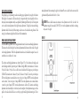
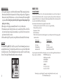
Model: 53-0021
Lit. #: 98-0579/04-05
Instruction Manual
INTRODUCTION
The Bushnell® Holosight® XLP is based on advanced holographic technology. The Bushnell®
Holosight® XLP enhances target acquisition, improves accuracy, and provides a high level of control
within the shooting environment. This user manual describes the features of the Bushnell® Holosight®
XLP and provides information on its use and maintenance. Please read the instructions carefully before
mounting and using the sight and always practice proper firearm safety.
Included:
• Assembled Holographic Diffraction Sight including mounting hardware
• 7/64” hex wrench (Weaver Base mount)
• 1/8” hex wrench (12 gauge model 1100, 870 or 1187 Remington® or similar)
BASIC OPERATION
The Bushnell® Holosight® XLP uses a laser to create an illuminated hologram in the display window
which appears as a virtual image of a reticle pattern. The reticle pattern appears to the user as a bright
red image which is projected onto the target plane. No laser light is projected onto the target. Note that
the Bushnell® Holosight® XLP has no magnification properties. Refer to Figure 1 for the user control
or adjustment features locations. Refer to the MOUNTING section for installation instructions and
correct placement on the gun.
1
FIGURE 1
2
BATTERIES
Two (2) Type AAA alkaline 1.5 V batteries are required to operate the Bushnell® Holosight® XLP. The
Bushnell® Holosight® XLP is designed to maintain constant brightness at a particular setting even as the
batteries drain through normal use. The reticle brightness will not fade gradually as the batteries drain,
but will shut down abruptly. The first indication of the batteries draining is the reticle image blinking
when the unit is turned on (see Electronic Features Section). Another indication of low batteries is the
reticle image blinking off and on during recoil. With high recoil guns, this can occur before the battery
check indicates low battery condition. If the reticle image blinks during recoil or turns off suddenly,
replace the batteries. Read and follow the battery replacement and battery check procedures described
in this Manual. Alkaline batteries are constructed differently by manufacturers. Tests show some brands
are more susceptible to degradation by the shock of recoil. The use of Eveready Energizer® batteries with
the Bushnell® Holosight® XLP is recommended.
INSTALLING OR REPLACING BATTERIES
To remove the battery compartment
cover, rotate the battery cover knurled
screw counterclockwise and carefully
pull the cover away from the sight
housing (Figure 2). After the battery
cover is removed, slide the batteries out
and replace them with a fresh set. The
plus and minus signs next to the battery
insertion area indicates the correct
FIGURE 2
3
polarity of the exposed contact of the battery. Check the polarity of the battery to be installed and insert
the battery so that the opposite polarity end goes into the battery compartment. To re-install the battery
cover, reverse the steps taken to remove the cover. DO NOT OVERTIGHTEN THE KNURLED
SCREW. Secure it with finger tightness only. Verify correct battery installation by turning on the sight
and checking that the reticle image appears. If the batteries are left in the sight backwards, they will be
drained of their power.
ELECTRONIC FEATURES
The Bushnell® Holosight® XLP controls are push-button switches located at the top of the unit as
shown in Figure 1. To ensure proper operation of the push button switches, press the switch firmly.
Audible and tactile feedback is provided when properly actuated.
1. ON/ Auto Battery Check
Pressing either the Up or Down push-button switch will turn the sight ON. If the Up arrow is used
to turn the sight ON it will be set at an 8 hour shutdown mode. That is, if the unit is not re-adjusted
for brightness for a period of 8 hours, it will turn off. If the Down arrow is used to turn the
sight ON it will be set at a 4 hour shutdown mode. See step 4 under this section for description of
Auto shutdown. The sight will automatically perform a battery check every time it is turned on. If
the batteries have less than 20% of life left, the sight will turn on with the reticle image blinking on
and off for 5 seconds. If the remaining battery life is more than 20%, the sight will turn on with a
steady reticle pattern. The battery condition can be checked any time by turning the sight off and on.
4
2. OFF
To turn the sight off press both UP and DOWN push-button switches simultaneously. Verify that
the unit is off by looking through the display window.
3. Brightness Adjustment
Push-button switches vary the brightness intensity of the holographic reticle image. Pressing and
releasing the push-button switch moves the brightness level UP or DOWN one (1) step from the
previous setting. Pressing and holding the Up or Down push-button switch will change the
brightness level up or down continuously. There are fifteen (15) brightness settings providing a
dynamic range of 100,000:1 from the lowest setting to the highest setting. When the sight is turned
ON, the brightness intensity level is at Level 10.
4. Auto Shutdown
The Bushnell® Holosight® XLP is equipped with an auto shutdown feature and will automatically
shut itself OFF 8 or 4 hours after the last push-button control is used. This is determined by the
method used to turn it ON in step 1.
MOUNTING
The Bushnell® Holosight® XLP is equipped with mounting hardware to attach to a Weaver-style rail or
to a 12 gauge model 1100, 870 or 1187 Remington® shotgun. To achieve the best results and accuracy,
the Bushnell® Holosight® XLP must be mounted properly. For the Weaver-style rail mount, the base
must be parallel to the bore to achieve the maximum elevation and windage adjustments.
5
To mount the sight to a Weaver-style rail, follow these steps, refer to Figure 3:
1. Loosen the 7/64” hex retainer screw that secures the clamp.
2. Place the sight onto the rail such that the unthreaded portion of the cross bolt is fitted into a groove on
the top of the Weaver-style rail. The user’s preference and the firearm will determine the optimal front
to back position on the rail.
3. With the cross bolt inserted fully into the rail’s groove, push the sight as far forward as possible.
4. Tighten the hex retainer screw to draw the retainer nut into secure and fully seated contact with the
opposite side of the rail.
FIGURE 3
NOTE: Loosen the retaining screw just enough to mount or remove the sight. It is not necessary to remove
the screw completely, as the lock hardware will not be retained in the sight and could be lost.
To mount the sight to a 12 gauge Remington model 870, 1100 or 1187 shotgun, follow these steps, refer
to Figure 4:
1. Remove the two through-pins from the shotgun.
2. Remove the two 1/8” hex retainer screws from the sight.
3. Place the sight onto the shotgun.
4. Re-install the two hex head screws through the sight and shotgun.
5. Tighten the two hex retainer screws to secure the sight to the shotgun.
FIGURE 4
6
7
BORE SIGHTING AND ZEROING
Bore sighting is a good preliminary procedure in achieving proper alignment of your sight to the firearm.
If the sight is to be mounted to a Weaver-style rail, it is imperative that the base be parallel to the bore.
Any major elevation adjustments may be accomplished by shimming the Weaver-style rail. It is important
not to use the elevation adjustment of the sight for major adjustments. The sight’s elevation and windage
adjustments should be used only for fine-tuning to achieve zero at the desired shooting distance. Final
zeroing of your firearm and sight should be done with live ammunition.
WINDAGE AND ELEVATION ADJUSTMENTS
The Bushnell® Holosight® XLP has rotating adjustment features for elevation and windage adjustments.
The feature at the back of the sight is the elevation adjustment and the feature at the front side of the sight
is the windage adjustment. Both of the adjustment features have a slotted head that requires the use of a
screwdriver, coin, or similar tool to rotate.
make adjustments before mounting the sight on the firearm. Be sure to check that the mount and the
sight remain fully secured after the first 2 to 3 shots.
CAUTION-When a sudden increase in resistance in the adjustment screw is felt, the end of the
adjustment range has been reached. DO NOT try to turn the adjustments any further or damage
may occur to the sight.
FIGURE 5
The elevation and windage adjustments are shown in Figure 5. For both elevation and windage, each
click will change the bullet’s point of impact 1/2 Minute of Angle (MOA), which translates to 1/4 inch at
50 yards, 1/2 inch at 100 yards. Also, one full rotation of either knob will change your point of impact
15 MOA. This translates into 8 inches at 50 yards, 15 inches at 100 yards. To move the point of impact
UP, turn the adjustment counterclockwise; to move the point of impact DOWN, turn the adjustment
screw clockwise. To move the point of impact RIGHT, turn the adjustment screw counterclockwise;
to move the point of impact LEFT, turn the adjustment screw clockwise. The elevation and windage
adjustments have been initially set at the factory near the midpoint of their adjustment ranges as well as
parallel to the rail, and should be close to zero with a properly installed sight and mounting rail. Do not
8
9
MAINTENANCE AND CARE
1. The holographic image glass is coated with anti-reflection material. When cleaning the glass surfaces,
first remove any dirt and dust with compressed air or by blowing on the glass surfaces. Fingerprints or
lubricants can be wiped off with lens tissue or a soft cotton cloth, moistened with lens cleaning fluid
or glass cleaner. Never clean the glass surface with a dry cloth or paper towel; always dampen the glass
surfaces prior to cleaning.
2. All moving parts of the sight are permanently lubricated. Do not try to lubricate them.
3. No maintenance is needed on the sight’s surface, except to occasionally wipe off with a soft cloth. Use
only a water-based cleaner such as glass cleaner, ammonia, or soap and water. Never use any solventtype cleaner such as alcohol or acetone.
4. Never disassemble the sight. The optical cavity is nitrogen filled and sealed. Disassembly will void the warranty.
LASER SAFETY
The Bushnell® Holosight® XLP is a Class II laser product. The laser’s illuminating beam, however, is
contained within the housing. The only laser light accessible to the eye is at a power level within the limit
of a Class IIa laser product. The laser’s illuminating beam can become accessible to the eye if the housing
is broken. Turn the sight off immediately and discontinue use until repaired.
10
WARRANTY / REPAIR
TWO-YEAR LIMITED WARRANTY
Your Bushnell® product is warranted to be free of defects in materials and workmanship for two years after the date of purchase. In
the event of a defect under this warranty, we will, at our option, repair or replace the product, provided that you return the product
postage prepaid. This warranty does not cover damages caused by misuse, improper handling, installation, or maintenance provided by
someone other than a Bushnell Authorized Service Department.
Any return made under this warranty must be accompanied by the items listed below:
1) A check/money order in the amount of $15.00 (USD) to cover the cost of postage and handling
2) Name and address for product return
3) An explanation of the defect
4) Proof of Date Purchased
5) Product should be well packed in a sturdy outside shipping carton, to prevent damage in transit, with return postage prepaid to
the address listed below:
IN U.S.A. Send To:
Bushnell Performance Optics
Attn.: Repairs
8500 Marshall Drive
Lenexa, Kansas 66214
IN CANADA Send To:
Bushnell Performance Optics
Attn.: Repairs
25A East Pearce Street, Unit 1
Richmond Hill, Ontario L4B 2M9
For products purchased outside the United States or Canada please contact your local dealer for applicable warranty information. In
Europe you may also contact Bushnell at:
BUSHNELL Performance Optics
Gmbh European Service Centre
MORSESTRASSE 4
D- 50769 KÖLN
GERMANY
Tél: +49 (0) 221 709 939 3
Fax: +49 (0) 221 709 939 8
This warranty gives you specific legal rights. You may have other rights which vary from country to country.
© 2005 Bushnell Performance Optics
11
ENGLISH
FCC COMPLIANCE
The Bushnell® Holosight® XLP complies with Part 15b of the FCC Rules. Operation is subject to the
following conditions: (1) this device may not cause harmful interference and (2) this device must accept
any interference received, including interference that may cause undesired operation.
12
13
©2005 Bushnell Performance Optics
www.bushnell.com


![SS HNBL-018 Owners manual HN1004-5 [EN] A3.indd - Jouef](http://vs1.manualzilla.com/store/data/006909007_1-61f91df4c9e84909195a3d6de9b86041-150x150.png)