1
SINAMICS G120
Power Module PM240
Hardware Installation Manual · 07/2009
SINAMICS
Answers for industry.
SINAMICS
SINAMICS G120
Power Module PM240
Introduction
1
Safety notes
2
Installing/Mounting
3
Connecting
4
Service and maintenance
5
Technical specifications
6
Accessories
7
Appendix
A
Hardware Installation Manual
Edition 07/2009
07/2009
A5E00807525B AD
Legal information
Warning notice system
This manual contains notices you have to observe in order to ensure your personal safety, as well as to prevent
damage to property. The notices referring to your personal safety are highlighted in the manual by a safety alert
symbol, notices referring only to property damage have no safety alert symbol. These notices shown below are
graded according to the degree of danger.
DANGER
indicates that death or severe personal injury will result if proper precautions are not taken.
WARNING
indicates that death or severe personal injury may result if proper precautions are not taken.
CAUTION
with a safety alert symbol, indicates that minor personal injury can result if proper precautions are not taken.
CAUTION
without a safety alert symbol, indicates that property damage can result if proper precautions are not taken.
NOTICE
indicates that an unintended result or situation can occur if the corresponding information is not taken into
account.
If more than one degree of danger is present, the warning notice representing the highest degree of danger will
be used. A notice warning of injury to persons with a safety alert symbol may also include a warning relating to
property damage.
Qualified Personnel
The device/system may only be set up and used in conjunction with this documentation. Commissioning and
operation of a device/system may only be performed by qualified personnel. Within the context of the safety notes
in this documentation qualified persons are defined as persons who are authorized to commission, ground and
label devices, systems and circuits in accordance with established safety practices and standards.
Proper use of Siemens products
Note the following:
WARNING
Siemens products may only be used for the applications described in the catalog and in the relevant technical
documentation. If products and components from other manufacturers are used, these must be recommended
or approved by Siemens. Proper transport, storage, installation, assembly, commissioning, operation and
maintenance are required to ensure that the products operate safely and without any problems. The permissible
ambient conditions must be adhered to. The information in the relevant documentation must be observed.
Trademarks
All names identified by ® are registered trademarks of the Siemens AG. The remaining trademarks in this
publication may be trademarks whose use by third parties for their own purposes could violate the rights of the
owner.
Disclaimer of Liability
We have reviewed the contents of this publication to ensure consistency with the hardware and software
described. Since variance cannot be precluded entirely, we cannot guarantee full consistency. However, the
information in this publication is reviewed regularly and any necessary corrections are included in subsequent
editions.
Siemens AG
Industry Sector
Postfach 48 48
90026 NÜRNBERG
GERMANY
Ordernumber: A5E00807525B AD
Ⓟ 07/2009
Copyright © Siemens AG 2006,
2007, 2009.
Technical data subject to change
Table of contents
1
Introduction................................................................................................................................................ 7
2
Safety notes............................................................................................................................................. 13
3
Installing/Mounting................................................................................................................................... 19
4
5
3.1
Air cooling requirements ..............................................................................................................20
3.2
Dimensions and drill pattern ........................................................................................................22
3.3
Control Unit installation ................................................................................................................32
Connecting .............................................................................................................................................. 35
4.1
Power distribution systems ..........................................................................................................36
4.2
Operation with ungrounded (IT) supplies.....................................................................................37
4.3
Operation with Residual Current Devices (RCD).........................................................................38
4.4
Motor cable length and cross section ..........................................................................................39
4.5
Access to power and motor terminals..........................................................................................42
4.6
Power and motor connections .....................................................................................................44
4.7
DC 24V power supply connection (FSGX) ..................................................................................46
4.8
Adjusting the fan voltage (FSGX) ................................................................................................47
4.9
Line contactor control (FSGX) .....................................................................................................48
4.10
ESD guidelines ............................................................................................................................49
Service and maintenance ........................................................................................................................ 51
5.1
Maintenance.................................................................................................................................51
5.2
5.2.1
5.2.2
5.2.3
5.2.4
Replacing components ................................................................................................................52
Replacing the cooling fan.............................................................................................................53
Replacing the cooling fan fuses and the cooling fan relay (FSGX) .............................................56
Power block replacement (FSGX) ...............................................................................................57
Control Interface Module replacement (FSGX) ...........................................................................61
6
Technical specifications........................................................................................................................... 65
7
Accessories ............................................................................................................................................. 75
7.1
7.1.1
7.1.2
7.1.3
7.1.4
Reactor and filter..........................................................................................................................76
Line reactor ..................................................................................................................................79
Line filter.......................................................................................................................................85
Output reactor ..............................................................................................................................89
Sine-wave filter.............................................................................................................................95
7.2
7.2.1
7.2.2
Brake chopper (FSGX) ..............................................................................................................101
Installing the Brake chopper (FSGX) .........................................................................................102
Connecting the brake chopper to the PM ..................................................................................104
Power Module PM240
Hardware Installation Manual, 07/2009, A5E00807525B AD
5
Table of contents
A
7.3
7.3.1
7.3.2
7.3.3
7.3.4
Braking Resistor........................................................................................................................ 107
Mounting the braking resistors.................................................................................................. 107
Connecting the braking resistor ................................................................................................ 113
Protecting the braking resistor .................................................................................................. 115
Technical specifications of the braking resistor ........................................................................ 116
7.4
7.4.1
7.4.2
7.4.3
Brake Relay............................................................................................................................... 118
Mounting the Brake Relay......................................................................................................... 118
Connecting the Brake Relay ..................................................................................................... 120
Technical specifications of the Brake Relay ............................................................................. 122
7.5
DIN rail mounting kit.................................................................................................................. 123
7.6
Screen termination kit ............................................................................................................... 123
Appendix................................................................................................................................................ 125
A.1
Electromagnetic Compatibility................................................................................................... 125
A.2
Definition of the EMC Environment and Categories ................................................................. 126
A.3
EMC Overall Performance ........................................................................................................ 128
A.4
Standards .................................................................................................................................. 130
A.5
Abbreviations ............................................................................................................................ 131
Index...................................................................................................................................................... 133
6
Power Module PM240
Hardware Installation Manual, 07/2009, A5E00807525B AD
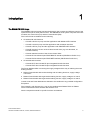
1
Introduction
The SINAMICS G120 range
The SINAMICS G120 inverter has been designed for the accurate and efficient control of the
speed and torque for three-phase motors. The SINAMICS G120 system comprises two basic
modules, the Control Unit (CU) and the Power Module (PM).
The Control Units are divided into the following:
● CU without fail-safe functions
– CU230P-2 HVAC for pump and fan applications with Modbus RTU interface
– CU230P-2 CAN for pump and fan applications with CANopen interface
– CU230P-2 DP for pump and fan applications with PROFIBUS DP interface
– CU240E economic version of the CU240 Control Units (e.g. less terminals, no
encoder interface)
– CU240S standard version of the CU240 Control Units
– CU240S DP like CU240S plus PROFIBUS DP interface (PROFIdrive Profile V4.1)
– CU240S PN like CU240S plus PROFINET interface (PROFIdrive Profile V4.1)
● CU with fail-safe functions
– CU240S DP-F like CU240S DP plus integrated fail-safe functions
– CU240S PN-F like CU240S PN plus integrated fail-safe functions
The Power Modules differ concerning the supply voltage and the way of realizing the motor
braking function:
● PM240 Power Module with resistor braking and dc braking functions, supply voltage
3 AC 400 V
● PM250 Power Module with regenerative braking function, supply voltage 3 AC 400 V
● PM260 Power Module with regenerative braking function, supply voltage 3 AC 690 V
Control Units and Power Modules are allowed to be combined in any possible configuration.
Exceptions:
The CU230P-2 with firmware V4.2 can not be combined with PM240 FSGX or PM260.
These combinations will be allowed with firmware V4.3.
See the respective manual for specific functions and features.
Power Module PM240
Hardware Installation Manual, 07/2009, A5E00807525B AD
7
Introduction
Available Power Modules PM240
There are the following types of PM240 Power Modules with braking capacity (resistor
braking). The given power rating values are defined for "high overload" operation.
● Unfiltered PM240 Power Modules
380 V … 480 V, IP20 or IPXXB, Frame size A … frame size GX, 0,37 kW … 200 kW
● PM240 Power Modules with integrated filter Class A
380 V … 480 V, IP20, Frame sizes B … F, 2,2 kW … 75 kW.
8
Power Module PM240
Hardware Installation Manual, 07/2009, A5E00807525B AD
Introduction
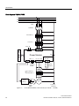
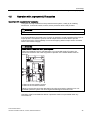
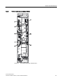
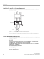
Block diagram PM240, FSA … FSF
/
/
/
3(
)XVH
&RQWDFWRU
/LQHUHDFWRU
/LQHILOWHU
&RQWURO8QLW
([WHUQDORULQWHJUDWHGLQ
WKH3RZHU0RGXOH
89:
///
3RZHU0RGXOH
89:
3(
'&3
5 5
%UDNLQJ
UHVLVWRU
2XWSXWUHDFWRU
RU
VLQHZDYHILOWHU
%UDNH
5HOD\
3(
0
a
3RZHU
VXSSO\
EUDNH
Figure 1-1
RSWLRQDO
DFFHVVRU\
Power Module PM240, frame size A … frame size F (HO 0.37 kW … 110 kW)
Power Module PM240
Hardware Installation Manual, 07/2009, A5E00807525B AD
9
Introduction
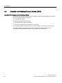
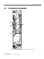
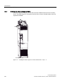
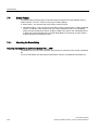
Block diagram PM240, FSGX
/
/
/
3(
)XVH
&RQWDFWRU
/LQHUHDFWRU
/LQHILOWHU
&RQWURO8QLW
390
89:
///
;
3RZHU0RGXOH
3(
%UDNHFKRSSHU
;
89:
2SWLRQDO
FRQWDFWRU
FRQWURO
5 5
%UDNLQJ
UHVLVWRU
2XWSXWUHDFWRU
RU
VLQHZDYHILOWHU
%UDNH
5HOD\
3(
0
a
3RZHU
VXSSO\
EUDNH
Figure 1-2
10
RSWLRQDO
DFFHVVRU\
Power Module PM240, frame size GX (HO 132 kW … 200 kW)
Power Module PM240
Hardware Installation Manual, 07/2009, A5E00807525B AD
Introduction
Available technical documentation
Comprehensive information and support tools are available from the Service and Support
internet site
● http://support.automation.siemens.com
You find there the following types of documentation:
● Getting Started
● Operating Instructions
● Hardware Installation Manual
● Function Manual
● Parameter Manual
● Product Information
Further internet addresses
You can download the respective documents for your inverter under the following links:
● SINAMICS G110
http://www.siemens.com/sinamics-g110
● SINAMICS G120
http://www.siemens.com/sinamics-g120
● SINAMICS G120D
http://www.siemens.com/sinamics-g120d
● SIMATIC ET 200S FC
http://www.siemens.com/et200s-fc
● SIMATIC ET 200pro FC
http://www.siemens.com/et200pro-fc
Application examples
You find various application examples to the inverters under the following link:
● http://support.automation.siemens.com/WW/view/en/20208582/136000
Power Module PM240
Hardware Installation Manual, 07/2009, A5E00807525B AD
11
Safety notes
2
Safety Instructions
The following Warnings, Cautions and Notes are provided for your safety and as a means of
preventing damage to the product or components in the connected machines. This section
lists Warnings, Cautions and Notes, which apply generally when handling the inverter,
classified as General, Transport and Storage, Commissioning, Operation, Repair and
Dismantling and Disposal.
Specific Warnings, Cautions and Notes that apply to particular activities are listed at the
beginning of the relevant sections in this manual and are repeated or supplemented at
critical points throughout these sections.
Please read the information carefully, since it is provided for your personal safety and will
also help prolong the service life of your inverter and the equipment to which it is connected.
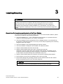
Common Instructions
It has to be ensured by the machine manufacturer, that the line-side overcurrent protection
equipment interrupts within 5 s (immovable equipment and modules in immovable
equipment) in the case of minimum fault current (current on complete insulation failure to
accessible conductive parts that are not live during operation and maximum current loop
resistance).
It has to be ensured by the machine manufacturer, that the voltage drop between the
beginning of the load system and the power drive system during operation with rated values
does not exceed 4 %.
Power Module PM240
Hardware Installation Manual, 07/2009, A5E00807525B AD
13
Safety notes
General
WARNING
This equipment contains dangerous voltages and controls potentially dangerous rotating
mechanical parts. Non-compliance with the warnings or failure to follow the instructions
contained in this manual can result in loss of life, severe personal injury or serious damage
to property.
Protection in case of direct contact by means of SELV / PELV is only permissible in areas
with equipotential bonding and in dry indoor rooms. If these conditions are not fulfilled,
other protective measures against electric shock must be applied e.g. protective insulation.
Only suitably qualified personnel should work on this equipment, and only after becoming
familiar with all safety notices, installation, operation and maintenance procedures
contained in this manual. The successful and safe operation of this equipment is dependent
upon its proper handling, installation, operation and maintenance.
As the earth leakage for this product can be greater than 3.5 mA a.c., a fixed earth
connection is required and the minimum size of the protective earth conductor shall comply
with the local safety regulations for high leakage current equipment.
The power supply, DC and motor terminals, the brake and thermistor cables can carry
dangerous voltages even if the inverter is inoperative. Wait at least five minutes to allow the
unit to discharge after switching off the line supply before carrying out any installation work.
It is strictly prohibited for any mains disconnection to be performed on the motor-side of the
system; any disconnection of the mains must be performed on the mains-side of the
Inverter.
When connecting the line supply to the Inverter, make sure that the terminal case of the
motor is closed.
This equipment is capable of providing internal motor overload protection according to
UL508C. Refer to P0610 and P0335, i²t is ON by default.
When changing from the ON to OFF-state of an operation if an LED or other similar display
is not lit or active; this does not indicate that the unit is switched-off or powered-down.
The inverter must always be grounded.
Isolate the line supply before making or changing connections to the unit.
Ensure that the inverter is configured for the correct supply voltage. The inverter must not
be connected to a higher voltage supply.
Static discharges on surfaces or interfaces that are not generally accessible (e.g. terminal
or connector pins) can cause malfunctions or defects. Therefore, when working with
inverters or inverter components, ESD protective measures should be observed.
Take particular notice of the general and regional installation and safety regulations
regarding work on dangerous voltage installations (e.g. EN 50178) as well as the relevant
regulations regarding the correct use of tools and personal protective equipment (PPE).
14
Power Module PM240
Hardware Installation Manual, 07/2009, A5E00807525B AD
Safety notes
CAUTION
Children and the general public must be prevented from accessing or approaching the
equipment!
This equipment may only be used for the purpose specified by the manufacturer.
Unauthorized modifications and the use of spare parts and accessories that are not sold or
recommended by the manufacturer of the equipment can cause fires, electric shocks and
injuries.
NOTICE
Keep this manual within easy reach of the equipment and make it available to all users.
Whenever measuring or testing has to be performed on live equipment, the regulations of
Safety Code BGV A2 must be observed, in particular § 8 "Permissible Deviations when
Working on Live Parts". Suitable electronic tools should be used.
Before installing and commissioning, please read these safety instructions and warnings
carefully and all the warning labels attached to the equipment. Make sure that the warning
labels are kept in a legible condition and replace missing or damaged labels.
Transport and storage
WARNING
Correct transport, storage as well as careful operation and maintenance are essential for
the proper and safe operation of the equipment.
CAUTION
Protect the equipment against physical shocks and vibration during transport and storage. It
is important that the equipment is protected from water (rainfall) and excessive
temperatures.
Commissioning
WARNING
Working on the equipment by unqualified personnel or failure to comply with warnings can
result in severe personal injury or serious damage to material. Only suitably qualified
personnel trained in the setup, installation, commissioning and operation of the product
should carry out work on the equipment.
Power Module PM240
Hardware Installation Manual, 07/2009, A5E00807525B AD
15
Safety notes
CAUTION
Cable connection
The control cables must be laid separately from the power cables. Carry out the
connections as shown in the installation section in this manual, to prevent inductive and
capacitive interference from affecting the correct function of the system.
Mechanical Installation
WARNING
To ensure the safe operation of the equipment, it must be installed and commissioned by
qualified personnel in full compliance with the warnings laid down in this manual.
Take particular note of the general and regional installation and safety regulations
regarding work on dangerous voltage installation (e.g. EN 61800-5-1) as well as the
relevant regulations regarding the correct use of tools and personal protective equipment
(PPE).
Electrical Installation
WARNING
Power and motor connections
A fixed location, non varying connection is necessary because of a leakage current
> 3.5 mA.
The inverter must always be grounded. If it is not grounded correctly, extremely dangerous
conditions may arise which could prove potentially fatal.
Isolate the mains electrical supply before making or changing connections to the unit.
The terminals of the Inverter can carry dangerous voltages even if the inverter is
inoperative. Wait at least 5 minutes to allow the unit to discharge after switching off the line
supply before carrying out any installation work.
When connecting the line supply to the inverter, make sure that the terminal case of the
motor is closed.
When changing from the ON to OFF-state of an operation if an LED or other similar display
is not lit or active; this does not indicate that the unit is switched-off or powered-down.
Ensure that the inverter is configured for the correct supply voltage – it must not be
connected to a higher voltage supply.
WARNING
Filtered drives can only be used on power systems with grounded starpoint.
16
Power Module PM240
Hardware Installation Manual, 07/2009, A5E00807525B AD
Safety notes
Operation
WARNING
The inverter operates at high voltages. When operating electrical devices, it is impossible to
avoid applying hazardous voltages to certain parts of the equipment.
The power supply and motor terminals - and if available the DC terminals - can carry
dangerous voltages even if the inverter is inoperative. Wait five minutes to allow the unit to
discharge after switching off the line supply before carrying out any installation work.
Emergency Stop facilities according to EN 60204, IEC 204 (VDE 0113) must remain
operative in all operating modes of the control equipment. Any disengagement of the
Emergency Stop facility must not lead to an uncontrolled or an undefined restart of the
equipment.
Wherever faults occurring in the control equipment can lead to substantial material damage
or even grievous bodily injury (that is, potentially dangerous faults), additional external
precautions must be taken or facilities provided to ensure or enforce safe operation, even
when a fault occurs (e.g. independent limit switches, mechanical interlocks, etc.).
Certain parameter settings may cause the inverter to restart automatically after an input
power failure, for example, the automatic restart function.
Motor parameters must be accurately configured for motor overload protection to operate
correctly.
This equipment is suitable for use in a power system up to 10,000 symmetrical amperes
(rms), for the maximum rated voltage + 10 % when protected by an appropriate standard
fuse (refer to the catalogue for the type of fuse).
The Power Modules are components with a high leakage current!
Use of mobile radio device (e.g. telephones, walky-talkies) with a transmission power > 1 W
in the immediate vicinity of the devices (< 1.5 m) can interfere with the functioning of the
equipment!
CAUTION
The line filter conducts a high leakage current via the PE conductor. Due to the high
leakage current a permanent PE connection for the line filter is required.
Furthermore, the following measures must be taken in accordance with EN 61800-5-1:
Either protective ground conductor cross-sections ≥ 10 mm2 (8 AWG) Cu or installation of a
second protective ground conductor with both having the same cross-section as the line
input cable.
Power Module PM240
Hardware Installation Manual, 07/2009, A5E00807525B AD
17
Safety notes
Repair
WARNING
Repairs on equipment may only be carried out by Siemens Service, by repair centers
authorized by Siemens or by authorized personnel who are thoroughly acquainted with all
the warnings and operating procedures contained in this manual.
Any defective parts or components must be replaced using parts contained in the relevant
spare parts list.
Disconnect the power supply before opening the equipment for access.
Dismantling and disposal
CAUTION
The packaging of the inverter is re-usable. Retain the packaging for future use.
Easy-to-release screw and snap connectors allow you to break the unit down into its
component parts. You can recycle these component parts, dispose of them in accordance
with local requirements or return them to the manufacturer.
18
Power Module PM240
Hardware Installation Manual, 07/2009, A5E00807525B AD
Installing/Mounting
3
WARNING
To ensure the safe operation of the equipment, it must be installed and commissioned by
qualified personnel in full compliance with the warnings laid down in this manual.
Take particular note of the general and regional installation and safety regulations
regarding work on dangerous voltage installation (e.g. EN 61800-5-1) as well as the
relevant regulations regarding the correct use of tools and personal protective equipment
(PPE).
General rules for the environmental protection of the Power Modules
To ensure that the power module is installed in the correct environmental conditions, please
ensure that you adhere to the following guidelines:
● The Power Module FSA … FSF is designed for IP20 protection. It is protected from the
ingress of solid foreign objects ≥ 12.5 mm (≥ 0.49 inches)
● The Power Module FSGX is designed for IP20 or IPXXB protection. It is protected from
the ingress of solid foreign objects ≥ 12.5 mm (≥ 0.49 inches) respectively from accessing
dangerous parts with a finger
● The Power Module is not protected against the ingress of water
● The Power Module is designed to be installed in an electrical cabinet
● Keep the Power Module free from dust and dirt
● Keep the Power Module away from water, solvents and chemicals
Take care to site the inverter away from potential water hazards, for example, do not
install the inverter beneath pipes that are subject to condensation. Avoid installing the
inverter where excessive humidity and condensation may occur
● Keep the Power Module within the maximum and minimum operating temperatures
● Ensure that the correct level of ventilation and air flow is provided
● Ensure that earthing and grounding practices for each Power Module and the cabinet
follows the guidelines given in this document (Page 49)
CAUTION
The SINAMICS G120 Power Module MUST NOT be mounted horizontally.
Power Module PM240
Hardware Installation Manual, 07/2009, A5E00807525B AD
19
Installing/Mounting
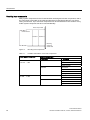
3.1 Air cooling requirements
3.1
Air cooling requirements
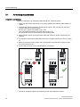
Installation and cooling
Make sure that there is an adequate airflow through the cubicle as follows:
1. Add the air flow values required for every Power Module (see following table) within the
cubicle
2. Calculate the airflow required by components as reactor, filter, Control Unit and other
electronic devices using the formula
Air flow (l/s) = (Power loss (Watt) / ΔT) x 0.86
(ΔT = Allowable temperature rise within the cubicle in °C).
For the power losses of components see the following table
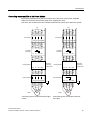
3. Add the airflow values of all components within the cubicle to get the complete air flow
required
4. No equipment should be installed that could have a negative effect on the flow of cooling
air
5. Make sure that the cooling vents in the Power Module are positioned correctly to allow
the free movement of air
6. Avoid cooling air short circuit using air barriers, if necessary
&RROLQJDLUIORZ
&RROLQJDLUIORZ
$LU
EDUULHU
$LUEDUULHU
Figure 3-1
Air barriers for avoiding cooling air short circuits
7. Provide an adequate cubicle with sufficient air vent and suitable air strainer
20
Power Module PM240
Hardware Installation Manual, 07/2009, A5E00807525B AD
Installing/Mounting
3.1 Air cooling requirements
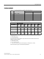
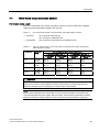
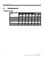
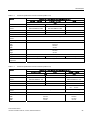
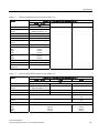
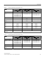
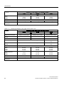
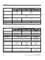
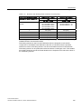
Air cooling requirements
Table 3- 1
Air cooling requirements for operation with rated power (LO)
Frame
size
LO power rating
FSA
FSB
FSC
Required cooling air flow
I/s
CFM
0.37 kW ... 1.5 kW
4.8
10
2.2 kW ... 4 kW
24
50
7.5 kW ... 15 kW
55
120
FSD
18.5 kW ... 30 kW
55
120
FSE
37 kW ... 45 kW
110
240
FSF
55 kW ... 132 kW
150
320
FSGX
160 kW ... 250 kW
360
760
Table 3- 2
Power losses of Power Module components in Watt
For Power Module
Power losses of …
FSA
FSB
FSC
FSD
FSE
FSF
FSGX
Power Module
100 …
110
140 …
180
240 …
400
440 …
720
1000 …
1300
1500 …
2500
3900 …
5500
170
210 …
280
230 …
310
Control Unit
<40
Line reactor
6 … 12
9 … 27
37
90
Line filter
0.5 …
1.5
2.0 …
4.0
7.5 … 15 -
-
60
60
Output reactor
5
20
60
200
200 …
270
500
470 …
500
Sine-wave filter
32 … 60
65 …
110
120 …
200
235 …
190
305
350 …
575
250 …
380
The power losses of line reactor and line filter are valid for the following operating conditions:
● Rated input current
● 50 Hz line frequency
The power losses of Power Module, output reactor and sine-wave filter are valid for the
following operating conditions:
● Rated output current
● 50 Hz output frequency
● 4 kHz pulse frequency (2 kHz pulse frequency for rated power > 75 kW)
Further information is given in the technical specifications.
Power Module PM240
Hardware Installation Manual, 07/2009, A5E00807525B AD
21
Installing/Mounting
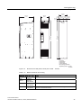
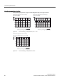
3.2 Dimensions and drill pattern
3.2
Dimensions and drill pattern
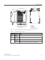
Dimensions, drill patterns and minimum distances
The dimension drawings for all frame sizes for the SINAMICS G120 Power Module PM240
are shown in the figures and not true to scale.
PP
PP
PP
+HLJKWLQFRPELQDWLRQZLWKWKH
VFUHHQWHUPLQDWLRQNLWZR%UDNH
5HOD\
PPLQFK
22
Figure 3-2
Dimensions and drill pattern, FSA (HO 0.37 kW ... 1.5 kW)
Table 3- 3
Minimum distances for mounting
PP
PP
PP
)RUIL[LQJ
[0EROWV
[0QXWV
[0ZDVKHUV
7LJKWHQLQJWRUTXH1P
OEILQ
Minimum distances FSA
Note
side by
side
30 mm
1.18 inches
At max. environmental temperature of 40° C (104° F) and with max. HO
load the Power Modules can be mounted adjacent to each other
above
100 mm
3.93 inches
below
100 mm
3.93 inches
front
40 mm
1.57 inches
Additional distance to the front with Control Unit CU240E
65 mm
2.56 inches
Additional distance to the front with Control Units CU240S,
CU240S DP, CU240S PN, CU240S DP-F and CU240S PN-F
Power Module PM240
Hardware Installation Manual, 07/2009, A5E00807525B AD
Installing/Mounting
3.2 Dimensions and drill pattern
PP
PP
PP
PP
+HLJKWLQFRPELQDWLRQZLWKWKHVFUHHQ
WHUPLQDWLRQNLWZR%UDNH5HOD\
PPLQFK
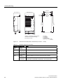
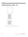
Figure 3-3
Dimensions and drill pattern, FSB (HO 2.2 kW ... 4 kW)
Table 3- 4
Minimum distances for mounting
PP
PP
PP
)RUIL[LQJ
[0EROWV
[0QXWV
[0ZDVKHUV
7LJKWHQLQJWRUTXH1P
OEILQ
Minimum distances FSB
Note
side by
side
30 mm
1.18 inches
At max. environmental temperature of 40° C (104° F) and with max. HO
load the Power Modules can be mounted adjacent to each other
above
100 mm
3.93 inches
below
100 mm
3.93 inches
front
40 mm
1.57 inches
Additional distance to the front with Control Unit CU240E
65 mm
2.56 inches
Additional distance to the front with Control Units CU240S,
CU240S DP, CU240S PN, CU240S DP-F and CU240S PN-F
Power Module PM240
Hardware Installation Manual, 07/2009, A5E00807525B AD
23
Installing/Mounting
3.2 Dimensions and drill pattern
PP
PP
PP
PP
+HLJKWLQFRPELQDWLRQZLWKWKHVFUHHQ
WHUPLQDWLRQNLWZR%UDNH5HOD\
PPLQFK
24
PP
PP
PP
)RUIL[LQJ
[0EROWV
[0QXWV
[0ZDVKHUV
7LJKWHQLQJWRUTXH1P
OEILQ
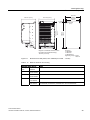
Figure 3-4
Dimensions and drill pattern, FSC (HO 5.5 kW ... 11 kW)
Table 3- 5
Minimum distances for mounting
Minimum distances FSC
Note
side by
side
50 mm
1.96 inches
At max. environmental temperature of 40° C (104° F) and with max. HO
load the Power Modules can be mounted adjacent to each other
above
125 mm
4.92 inches
below
125 mm
4.92 inches
front
40 mm
1.57 inches
Additional distance to the front with Control Unit CU240E
65 mm
2.56 inches
Additional distance to the front with Control Units CU240S,
CU240S DP, CU240S PN, CU240S DP-F and CU240S PN-F
Power Module PM240
Hardware Installation Manual, 07/2009, A5E00807525B AD
Installing/Mounting
3.2 Dimensions and drill pattern
PPರ
+HLJKWLQFRPELQDWLRQZLWKWKHVFUHHQ
WHUPLQDWLRQNLWZR%UDNH5HOD\
PPLQFK
PP
PP
PPರ
PP
PP
PP
PP
PPರ
)RUIL[LQJ
[0EROWV
[0QXWV
[0ZDVKHUV
7LJKWHQLQJWRUTXH1P
OEILQ
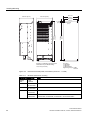
Figure 3-5
Dimensions and drill pattern, FSD unfiltered (HO 15 kW ... 22 kW)
Table 3- 6
Minimum distances for mounting
Minimum distances FSD
Note
side by
side
0 mm
0 inches
above
300 mm
11.81 inches
below
300 mm
11.81 inches
front
40 mm
1.57 inches
Additional distance to the front with Control Unit CU240E
65 mm
2.56 inches
Additional distance to the front with Control Units CU240S,
CU240S DP, CU240S PN, CU240S DP-F and CU240S PN-F
Power Module PM240
Hardware Installation Manual, 07/2009, A5E00807525B AD
25
Installing/Mounting
3.2 Dimensions and drill pattern
+HLJKWLQFRPELQDWLRQZLWKWKH
VFUHHQWHUPLQDWLRQNLWZR%UDNH
5HOD\
PPLQFK
)RUIL[LQJ
[0EROWV
[0QXWV
[0ZDVKHUV
7LJKWHQLQJWRUTXH1P
OEILQ
Figure 3-6
Dimensions and drill pattern, FSD filtered (HO 15 kW ... 22 kW)
Table 3- 7
Minimum distances for mounting
Minimum distances FSD
26
PP
PP
PPರ
PP
PP
PP
PP
PPರ
PPರ
Note
side by
side
0 mm
0 inches
above
300 mm
11.81 inches
below
300 mm
11.81 inches
front
40 mm
1.57 inches
Additional distance to the front with Control Unit CU240E
65 mm
2.56 inches
Additional distance to the front with Control Units CU240S,
CU240S DP, CU240S PN, CU240S DP-F and CU240S PN-F
Power Module PM240
Hardware Installation Manual, 07/2009, A5E00807525B AD
Installing/Mounting
3.2 Dimensions and drill pattern
PPರ
PPರ
+HLJKWLQFRPELQDWLRQZLWKWKHVFUHHQ
WHUPLQDWLRQNLWZR%UDNH5HOD\
PPLQFK
PP
PP
PP
PPರ
PP
PP
PP
)RUIL[LQJ
[0EROWV
[0QXWV
[0ZDVKHUV
7LJKWHQLQJWRUTXH1P
OEILQ
Figure 3-7
Dimensions and drill pattern, FSE unfiltered (HO 30 kW ... 37 kW)
Table 3- 8
Minimum distances for mounting
Minimum distances FSE
Note
side by
side
0 mm
0 inches
above
300 mm
11.81 inches
below
300 mm
11.81 inches
front
40 mm
1.57 inches
Additional distance to the front with Control Unit CU240E
65 mm
2.56 inches
Additional distance to the front with Control Units CU240S,
CU240S DP, CU240S PN, CU240S DP-F and CU240S PN-F
Power Module PM240
Hardware Installation Manual, 07/2009, A5E00807525B AD
27
Installing/Mounting
3.2 Dimensions and drill pattern
PPರ
+HLJKWLQFRPELQDWLRQZLWKWKHVFUHHQ
WHUPLQDWLRQNLWZR%UDNH5HOD\
PPLQFK
)RUIL[LQJ
[0EROWV
[0QXWV
[0ZDVKHUV
7LJKWHQLQJWRUTXH1P
OEILQ
Figure 3-8
Dimensions and drill pattern, FSE filtered (HO 30 kW ... 37 kW)
Table 3- 9
Minimum distances for mounting
Minimum distances FSE
28
PP
PP
PPರ
PP
PP
PP
PP
PPರ
Note
side by
side
0 mm
0 inches
above
300 mm
11.81 inches
below
300 mm
11.81 inches
front
40 mm
1.57 inches
Additional distance to the front with Control Unit CU240E
65 mm
2.56 inches
Additional distance to the front with Control Units CU240S,
CU240S DP, CU240S PN, CU240S DP-F and CU240S PN-F
Power Module PM240
Hardware Installation Manual, 07/2009, A5E00807525B AD
Installing/Mounting
3.2 Dimensions and drill pattern
PP
PP
PPರ
PPರ
+HLJKWLQFRPELQDWLRQZLWKWKHVFUHHQ
WHUPLQDWLRQNLWZR%UDNH5HOD\
PPLQFK
PP
PP
PP
PP
)RUIL[LQJ
[0EROWV
[0QXWV
[0ZDVKHUV
7LJKWHQLQJWRUTXH1P
OEILQ
Figure 3-9
Dimensions and drill pattern, FSF unfiltered (HO 45 kW ... 110 kW)
Table 3- 10
Minimum distances for mounting
Minimum distances FSF
Note
side by
side
0 mm
0 inches
above
350 mm
13.77 inches
below
350 mm
13.77 inches
front
40 mm
1.57 inches
Additional distance to the front with control unit CU240E
65 mm
2.56 inches
Additional distance to the front with Control Units CU240S,
CU240S DP, CU240S PN, CU240S DP-F and CU240S PN-F
Power Module PM240
Hardware Installation Manual, 07/2009, A5E00807525B AD
29
Installing/Mounting
3.2 Dimensions and drill pattern
PPರ
+HLJKWLQFRPELQDWLRQZLWKWKHVFUHHQ
WHUPLQDWLRQNLWZR%UDNH5HOD\
PPLQFK
PP
PP
PP
PP
)RUIL[LQJ
[0EROWV
[0QXWV
[0ZDVKHUV
7LJKWHQLQJWRUTXH1P
OEILQ
Figure 3-10
Dimensions and drill pattern, FSF filtered (HO 45 kW ... 110 kW)
Table 3- 11
Minimum distances for mounting
Minimum distances FSF
30
PP
PP
PPರ
Note
side by
side
0 mm
0 inches
above
350 mm
13.77 inches
below
350 mm
13.77 inches
front
40 mm
1.57 inches
Additional distance to the front with control unit CU240E
65 mm
2.56 inches
Additional distance to the front with Control Units CU240S,
CU240S DP, CU240S PN, CU240S DP-F and CU240S PN-F
Power Module PM240
Hardware Installation Manual, 07/2009, A5E00807525B AD
Installing/Mounting
3.2 Dimensions and drill pattern
PP
PP
PP
PP PP
PP
PP
PP
PP
PP
PP
)RUIL[LQJ
[0EROWV
[0QXWV
[0ZDVKHUV
8VHORFNLQJHOHPHQWV
7LJKWHQLQJWRUTXH1P
OEILQ
Figure 3-11
Dimensions and drill pattern, FSGX (HO 132 kW ... 200 kW)
Table 3- 12
Minimum distances for mounting
Minimum distances FSGX
side by
side
0 mm
0 inches
above
250 mm
9.84 inches
below
150 mm
5.91 inches
front
50 mm
1.97 inches
Note
The CU is mounted inside the Power Module housing and does not
influence the PM dimensions
Power Module PM240
Hardware Installation Manual, 07/2009, A5E00807525B AD
31
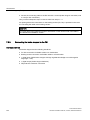
Installing/Mounting
3.3 Control Unit installation
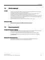
3.3
Control Unit installation
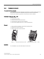
Fitting the CU to the PM FSA ... FSF
The Control Unit is snapped onto the Power Module as shown in the figure below. To
disconnect the CU push the release button on top of the PM.
The process of fitting the Control Unit to the Power Module is the same technique
independent from the type of Control Unit or Power Module.
Figure 3-12
32
Fitting the Control Unit CU240S to the Power Module FSC
Power Module PM240
Hardware Installation Manual, 07/2009, A5E00807525B AD
Installing/Mounting
3.3 Control Unit installation
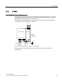
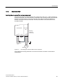
Fitting the CU to the Power Module FSGX
The Control Unit is snapped inside the Power Module housing behind the front plate.
1. Unscrew the two fixing screws at the bottom of the
front cover.
2. Push the cover upwards and remove it.
3. and 4. Snap the Control Unit onto the Power Module.
5HOHDVHEXWWRQ
To disconnect the CU push the release button.
Power Module PM240
Hardware Installation Manual, 07/2009, A5E00807525B AD
33
Installing/Mounting
3.3 Control Unit installation
Adapting the CU frame of the Power Module front cover
A plastic frame in the front cover of the Power Module ensures the IP20 or IPXXB protection
class of the inverter. This plastic frame has to be adapted to the Control Unit:
● The frame can be adapted by removing its bottom
● The plastic insert can be reduced or removed
Control Unit
Actions to take
CU240S
CU240S DP
CU240S DP-F
CU240S PN
CU240S PN-F
① Reduce the insert
② Remove the bottom of the frame
Frame adaptation
(view from behind)
IP20 protection is ensured with a
correctly adapted frame and with
the Control Units listed above.
CU240E
① Use the insert as it is
② Remove the bottom of the frame
IPXXB protection is ensured with a
correctly adapted frame and with
the Control Unit CU240E
34
Power Module PM240
Hardware Installation Manual, 07/2009, A5E00807525B AD
4
Connecting
Electrical Installation
WARNING
Power and motor connections
A fixed location, non varying connection is necessary because of a leakage current
> 3.5 mA.
The inverter must always be grounded. If it is not grounded correctly, extremely dangerous
conditions may arise which could prove potentially fatal.
Isolate the mains electrical supply before making or changing connections to the unit.
The terminals of the Inverter can carry dangerous voltages even if the inverter is
inoperative. Wait at least 5 minutes to allow the unit to discharge after switching off the line
supply before carrying out any installation work.
When connecting the line supply to the inverter, make sure that the terminal case of the
motor is closed.
When changing from the ON to OFF-state of an operation if an LED or other similar display
is not lit or active; this does not indicate that the unit is switched-off or powered-down.
Ensure that the inverter is configured for the correct supply voltage – it must not be
connected to a higher voltage supply.
WARNING
Filtered drives can only be used on power systems with grounded starpoint.
Power Module PM240
Hardware Installation Manual, 07/2009, A5E00807525B AD
35
Connecting
4.1 Power distribution systems
4.1
Power distribution systems
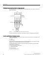
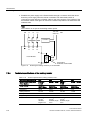
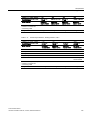
Overview of Power Distribution Systems
The power distribution systems described below, as defined in EN 60950 , have been
considered in the design of the inverter. In the next figures three phase systems are outlined.
The three phase inverter must be connected to L1, L2 and L3. PE must always be
connected. The inverter will operate with most supply systems.
Table 4- 1
Power distribution systems
TN-S Power System
TN-C-S Power System TN-C Power System
TT Power System
IT Power System
/
/
/
1
3(
/
/
/
/
/
/
1
/
/
/
1
1
3(
1
3(
/
/
/
1
3(
/ / /
/ / /
/ / /
Exposed
Conductive Parts
Exposed
Conductive Parts
Exposed
Conductive Parts
A TN-S power system
has separate neutral
and protective ground
conductors throughout
the system.
In a TN-C-S power
system, the neutral
and protective
functions are
combined in a single
part of the system.
/ / /
Exposed
Conductive
Parts
In a TN-C power
system, the neutral
and protective
functions are
combined in a single
conductor throughout
the system.
/ / /
3(
A TT power system
has one point directly
grounded, the
exposed conductive
parts of the installation
being connected to a
ground, which is
electrically
independent of the
ground of the power
system.
Exposed
Conductive
Parts
3(
An IT power system
has no direct
connection to ground instead the exposed
parts of the electrical
installation are
grounded.
WARNING
Filtered drives can only be used on power systems with grounded starpoint.
Note
For fulfilling the protection class I according to EN 61140 the input and output supply
voltages have to be earthed.
36
Power Module PM240
Hardware Installation Manual, 07/2009, A5E00807525B AD
Connecting
4.2 Operation with ungrounded (IT) supplies
4.2
Operation with ungrounded (IT) supplies
Operation with ungrounded (IT) supplies
IT supplies are fully isolated from the protective earth system, usually by an isolating
transformer. It should be noted, however, that a protective earth is still provided.
WARNING
Power Modules with built-in filters or external filters must not be used with IT supplies.
If the Power Module connected to an IT supply is required to remain operational if an input or
output phase is connected to ground, then an output reactor must be fitted to prevent
overcurrent tripping. The probability of overcurrent tripping without output reactor increases
with the size of the IT supply.
WARNING
Power Module FSGX from an IT power system
If the Power Module FSGX is operated from a non-grounded supply/IT system, the
connection bracket for the noise suppression capacitor of the Power Module must be
removed.
1: Remove the two retaining screws
2: Remove the connection bracket
Failing to remove the connection bracket for the noise suppression capacitor on a nongrounded system/IT system can cause significant damage to the built-in unit.
Operation of the Power Modules without a protective earth is not permitted under any
circumstances.
Power Module PM240
Hardware Installation Manual, 07/2009, A5E00807525B AD
37
Connecting
4.3 Operation with Residual Current Devices (RCD)
4.3
Operation with Residual Current Devices (RCD)
Operation with Residual Current Devices (RCD)
If an RCD (also referred to as an ELCB or a RCCB) is fitted, the Power Module will operate
without nuisance tripping provided that:
● A type B RCD is used.
● The trip limit of the RCD is 300 mA.
● The neutral of the supply is grounded.
● Only one Power Module is supplied from each RCD.
● The output cables are less than 50 m (164 ft) screened or 100 m (328 ft) unscreened.
If no RCD is used, the touch protection can be achieved by double insulation or by
separating the Power Module from the mains system using a transformer.
38
Power Module PM240
Hardware Installation Manual, 07/2009, A5E00807525B AD
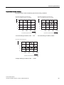
Connecting
4.4 Motor cable length and cross section
4.4
Motor cable length and cross section
Permissible Cable Length
The use of unshielded motor cables is possible. However to meet C2 EMI class, shielded
cables with appropriate EMI installation are required.
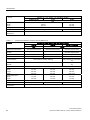
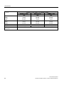
Table 4- 2
The inverters will operate at full specification with cable lengths as follows
• Screened
25 m (80 ft) for filtered drives
50 m (160 ft) for unfiltered drives
• Unscreened
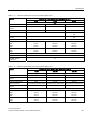
Table 4- 3
Frame size
100 m (330 ft) for both filtered and unfiltered drives
Using an output reactor or a sine-wave filter as specified in the catalog, the following
cable lengths are possible
Max. permissable motor cable length using …
HO power
rating
… an output reactor with …
… screened
cables
… unscreened
cables
… a sine-wave filter with …
… screened
cables
… unscreened
cables
FSA
0.37 kW ...
1.5 kW
100 m
110 yd.
100 m
110 yd.
200 m
220 yd.
300 m
330 yd.
FSB … FSC
2.2 kW ...
11 kW
100 m
110 yd.
150 m
160 yd.
200 m
220 yd.
300 m
330 yd.
FSD … FSF
15 kW ...
110 kW
200 m
220 yd.
300 m
330 yd.
200 m
220 yd.
300 m
330 yd.
FSGX
132 kW ...
200 kW
300 m
330 yd.
450 m
490 yd.
300 m
330 yd.
450 m
490 yd.
CAUTION
The control cables must be laid separately from the power cables. The connection must be
carried out as shown in the installation section in this manual, to prevent inductive and
capacitive interference from affecting the correct function of the system.
Note
Ensure that the appropriate circuit-breakers or fuses with the specified current rating are
connected between the power supply and the inverter. The technical specifications contain
information about the circuit breaker and fuses. See Technical specifications (Page 65).
Power Module PM240
Hardware Installation Manual, 07/2009, A5E00807525B AD
39
Connecting
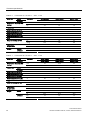
4.4 Motor cable length and cross section
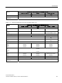
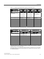
Table 4- 4
Cable cross section
Frame size
Cable cross section
kW
mm2
AWG
Tightening torques
Nm
lbf in
0.37:
1.0 … 2.5
18 … 14
1.1
9.7
0.55:
1.0 … 2.5
18 … 14
1.1
9.7
0.75:
1.0 … 2.5
18 … 14
1.1
9.7
1.1:
1.0 … 2.5
18 … 14
1.1
9.7
1.5:
1.0 … 2.5
18 … 14
1.1
9.7
2.2:
1.5 … 6.0
16 … 10
1.5
13
3:
1.5 … 6.0
16 … 10
1.5
13
4:
2.5 … 6.0
14 … 10
1.5
13
5.5:
4.0 … 10
12 … 8
2.3
20
7.5:
4.0 … 10
12 … 8
2.3
20
11:
6.0 … 10
10 … 8
2.3
20
15:
10 … 35
7…2
6
53
18.5:
10 … 35
7…2
6
53
22:
16 … 35
5…2
6
53
30:
25 … 35
3…2
6
53
37:
25 … 35
3…2
6
53
45:
35 … 120
2 … 4/0
13
115
55:
70 … 120
2/0 … 4/0
13
115
75:
95 … 120
3/0 … 4/0
13
115
90:
95 … 120
3/0 … 4/0
13
115
110:
95 … 120
3/0 … 4/0
13
115
132
95 ... 2 x 240
3/0 … 2 x 600
14
120
160
120 ... 2 x 240
4/0 … 2 x 600
14
120
200
185 ... 2 x 240
6/0 … 2 x 600
14
120
FSA
FSB
FSC
FSD
FSE
FSF
FSGX
40
Power Module PM240
Hardware Installation Manual, 07/2009, A5E00807525B AD
Connecting
4.4 Motor cable length and cross section
CAUTION
Cable cross section for grounding
For power cables up to 10 mm² (Cu) or 16 mm² (Al) the earth cable must be at least as big
as the power cables.
For power cables larger than 10 mm² (Cu) or 16 mm² (Al) the earth cable must be at least
10 mm² (Cu) or 16 mm² (Al), but need not exceed these sizes.
Power Module PM240
Hardware Installation Manual, 07/2009, A5E00807525B AD
41
Connecting
4.5 Access to power and motor terminals
4.5
Access to power and motor terminals
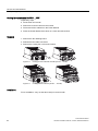
Accessing the power and motor terminals
Frame sizes A … C have no terminal covers.
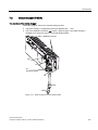
Frame sizes D … F terminal covers are accessed by the following steps, as shown in the
figure below:
1. Release the latch on each side of the terminal covers with a suitable flat-bladed
screwdriver
2. Push the cover upwards
3. Lock the cover into position
Figure 4-1
42
Access the power and motor terminals on FSD … FSF
Power Module PM240
Hardware Installation Manual, 07/2009, A5E00807525B AD
Connecting
4.5 Access to power and motor terminals
The terminals of FSGX are accessed by removing the front cover:
1. Unscrew the two fixing screws at the bottom of the
front cover
2. Push the cover upwards and remove it
Power Module PM240
Hardware Installation Manual, 07/2009, A5E00807525B AD
43
Connecting
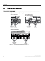
4.6 Power and motor connections
4.6
Power and motor connections
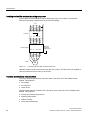
Power and motor terminal layout
The figures below show the layout of the power and motor terminals of the Power Module.
The figure also includes the tightening torques for the terminals.
)6$1POEILQ
6XSSO\YROWDJH 0RWRU
FRQQHFWLRQ FRQQHFWLRQ
)6%1POEILQ
)6&1POEILQ
6XSSO\YROWDJH
FRQQHFWLRQ
0RWRU
FRQQHFWLRQ
)6'(01POEILQ
)6)01POEILQ
6XSSO\YROWDJH
FRQQHFWLRQ
Figure 4-2
44
0RWRU
FRQQHFWLRQ
Power and motor terminal layout for the FSA ... F
Power Module PM240
Hardware Installation Manual, 07/2009, A5E00807525B AD
Connecting
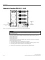
4.6 Power and motor connections
6XSSO\YROWDJHFRQQHFWLRQ
3(
%UDNHFKRSSHU
FRQQHFWLRQ
:
9
8
'&3$
'&1$
3(89:
0RWRUFRQQHFWLRQ
Figure 4-3
Power and motor terminal layout for the FSGX
M10 tightening torque: 25 Nm/18.4 lbf.ft
Power Module PM240
Hardware Installation Manual, 07/2009, A5E00807525B AD
45
Connecting
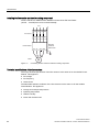
4.7 DC 24V power supply connection (FSGX)
4.7
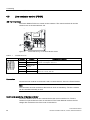
DC 24V power supply connection (FSGX)
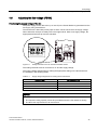
-X9: Terminal block
The Power Module FSGX requires a separate DC 24V power supply. The power supply is
connected to the X9 terminal block of the Power Module.
Figure 4-4
Table 4- 5
-X9 terminal block ① on the Power Module FSGX
Terminal block -X9
Terminal
Function
1
P24V
2
M
3
Reserved, do not use
4
Reserved, do not use
Technical specifications
Voltage: 24 V DC (20.4 V - 28.8 V)
Current consumption: max. 4 A
5
HS1
Line contactor control
6
HS2
Line contactor control
Max. connectable cross-section: 1.5 mm²
Connection
Connect the external DC 24 V supply to terminals 1 (P 24 V) and 2 (Mext) of terminal
block -X9 on the Power Module.
NOTICE
Not connected 24V power supply lead to a fault message of the inverter as soon as the
400V power supply is disconnected from the Power Module.
46
Power Module PM240
Hardware Installation Manual, 07/2009, A5E00807525B AD
Connecting
4.8 Adjusting the fan voltage (FSGX)
4.8
Adjusting the fan voltage (FSGX)
Fine-tuning the supply voltage of the fan
The power supply for the device fan (1 AC 230 V) in the Power Module is generated from the
line supply using a transformer.
The transformer is fitted with primary taps so that it can be fine-tuned to the supply voltage.
When delivered, the taps are always set to the highest level. With a low supply voltage, the
appropriate transformer tap must be activated.
Figure 4-5
99 99
Setting terminals for the fan transformer PM240 FSGX
The setting terminals must be connected to "0" and the supply voltage.
The supply voltage assignments for making the appropriate setting on the fan transformer
are indicated in the following tables.
Table 4- 6
Supply voltage assignments for setting the fan transformer
Supply voltage
Fan transformer tap
380 V ± 10%
380 V
400 V ± 10%
400 V
440 V ± 10%
440 V
480 V ± 10%
480 V
NOTICE
If the terminals are not reconnected to the actual supply voltage:
• The required cooling capacity cannot be provided because the fan rotates too slowly;
• The fan fuses may blow due to an overcurrent.
Power Module PM240
Hardware Installation Manual, 07/2009, A5E00807525B AD
47
Connecting
4.9 Line contactor control (FSGX)
4.9
Line contactor control (FSGX)
-X9: Terminal block
The Power Module FSGX can control its line contactor. The control terminals for the line
contactor are on the terminal block -X9.
Figure 4-6
Table 4- 7
-X9 terminal block ① on the Power Module FSGX
Terminal block -X9
Terminal
1
Function
P24V
Technical specifications
Voltage: 24 V DC (20.4 V - 28.8 V)
Current consumption: max. 4 A
2
M
3
4
Reserved, do
not use
5
HS1
Line contactor control
6
HS2
230 V AC ± 15 %, 400 mA
Max. connectable cross-section: 1.5 mm²
Connection
Connect the line contactor to terminals 5 and 6 of terminal block –X9 on the Power Module.
Note
The connection of a line contactor to the terminal -X9 is not mandatory. The line contactor
can be controlled externally as well.
Control and monitoring of the line contactor
The Power Module closes its line contactor before the motor is switched on. The line
contactor is opened after the motor is switched off. The Power Module monitors the line
voltage after a tolerance time if the motor is switched on.
48
Power Module PM240
Hardware Installation Manual, 07/2009, A5E00807525B AD
Connecting
4.10 ESD guidelines
4.10
ESD guidelines
Avoiding Electromagnetic Interference (EMI)
The inverters are designed to operate in an industrial environment where a high level of EMI
can be expected. Most installations do not give problems. However, it is good engineering
practice to conform to the following guidelines - this will reduce the likelyhood of problems
during operation.
Actions to take
● Ensure that all equipment in the cubicle is well grounded using short, thick grounding
cable connected to a common star point or busbar.
● Make sure that any control equipment (such as a PLC) connected to the inverter is
connected to the same ground or star point as the inverter using a short thick link.
● Connect the return ground from the motors directly to the ground connection (PE) on the
associated inverter.
● Flat conductors are preferred as they have lower impedance at higher frequencies.
● Terminate the ends of the cable neatly, ensuring that unscreened wires are as short as
possible.
● Separate the control cables from the power cables as much as possible, using separate
trunking, if the cables cross they should cross at 90º to each other.
● Whenever possible, use screened leads for the connections to the control circuitry.
● Ensure that the contactors in the cubicle are suppressed, either with R-C suppressors for
AC contactors or 'flywheel' diodes for DC contactors fitted to the coils. Varistor
suppressors are also effective. This is important when the contactors are controlled from
the inverter relay.
● Use screened or armored cables for the motor connections and ground the screen at
both ends using the cable clamps.
WARNING
Safety regulations must not be compromised when installing inverters!
Screening methods
For all frame sizes the Screen Termination Kit is supplied as an optional extra. It allows easy
and efficient connection of the necessary screening. For further details on the Screen
Termination Kit, please refer to the SINAMICS G120 catalog.
Power Module PM240
Hardware Installation Manual, 07/2009, A5E00807525B AD
49
Connecting
4.10 ESD guidelines
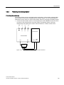
Screening without a Screen Termination Kit
In order to meet radiated emissions a screen termination kit must be used. Screening without
a screen termination kit is only suitable for installation in a metal cabinet.
Should a Screen Termination Kit not be available, the inverter then can be screened using
the methodology shown in the figure below. This diagram shows both methodologies of
screening.
Note
The EMI illustration below is not to scale. The terminal cover on Frame Size D cannot be
removed. It has been removed to show the correct cable connection for the terminals.
①
Line power input
②
Motor cable
③
Metal back plate
④
Use suitable clips to fix motor and power cable screen securely to metal back plate
⑤
Screen cables
⑥
Screen Termination Kit
⑦
Gromments
Figure 4-7
50
Example of wiring to minimize the effect of EMI
Power Module PM240
Hardware Installation Manual, 07/2009, A5E00807525B AD
Service and maintenance
5.1
5
Maintenance
The purpose of maintenance is to preserve the specified condition of the Power Module. Dirt
and contamination must be removed regularly and parts subject to wear replaced. The
Power Module comprises mostly electronic components. Apart from the fan(s), the unit,
therefore, contains hardly any components that are subject to wear or that require
maintenance or servicing.
The following points must generally be observed.
Dust deposits
Dust deposits inside the Power Module must be removed at regular intervals by qualified
personnel in line with the relevant safety regulations. The unit must be cleaned using a brush
and vacuum cleaner, and dry compressed air (max. 1 bar) for areas that cannot be easily
reached.
Ventilation
When installing the devices in a cabinet, make sure that the cabinet ventilation slots are not
obstructed. The fan must be checked to make sure that it is functioning correctly.
Cable and screw terminals
Cable and screw terminals must be checked regularly to ensure that they are secure in
position, and if necessary, retightened. Cabling must be checked for defects. Defective parts
must be replaced immediately.
Note
The actual intervals at which maintenance procedures are to be performed depend on the
installation conditions and the operating conditions.
Siemens offers its customers support in the form of a service contract. For further details,
contact your regional office or sales office.
Power Module PM240
Hardware Installation Manual, 07/2009, A5E00807525B AD
51
Service and maintenance
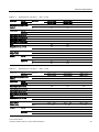
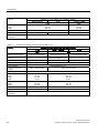
5.2 Replacing components
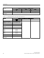
5.2
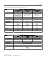
Replacing components
Power Module spare parts
Spare part
available (✓) or not available (-) for Power Module ...
FSA
0.37 kW
...
1.5 kW
52
FSB
2.2 kW
...
4 kW
FSC
5.5 kW
...
11 kW
FSD
15 kW
...
22 kW
FSE
30 kW
...
37 kW
FSF
45 kW
...
110 kW
FSGX
132 kW
...
200 kW
Fan
✓
✓
✓
✓
✓
✓
✓
Fan transformer
-
-
-
-
-
-
✓
Fan fuses
-
-
-
-
-
-
✓
Fan relay
-
-
-
-
-
-
✓
CIM (Control Interface
Module)
-
-
-
-
-
-
✓
Power block
-
-
-
-
-
-
✓
Front cover
-
-
-
-
-
-
✓
Power Module PM240
Hardware Installation Manual, 07/2009, A5E00807525B AD
Service and maintenance
5.2 Replacing components
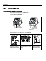
5.2.1
Replacing the cooling fan
The service life of the cooling fan
The average service life of the cooling fans is 50,000 hours. In practice, however, the service
life may deviate from this value. Especially a dusty environment can occlude the fan.
The fan must be replaced in good time to ensure that the inverter is available.
Replacing the cooling fan FSA … FSC
Preparatory steps
● Power-down the inverter
● Remove the Control Unit from the inverter
● Disconnect all the cables from the Power Module
● Place the Power Module face-down on a clean and safe surface
Removal
1. Using a posi-drive screwdriver, remove the fan retaining screws
2. Release the fan cable connector(s)
3. Slide the cooling fan out from the inverter
Figure 5-1
Cooling fan removal FSA (0.37 kW … 1.5 kW), FSB and FSC (2.2 kW … 11 kW)
Installation
For re-installation, carry out the above steps in reverse order.
Power Module PM240
Hardware Installation Manual, 07/2009, A5E00807525B AD
53
Service and maintenance
5.2 Replacing components
Cooling fan replacement for FSD … FSF
Preparatory steps
● Power-down the inverter
● Remove the Control Unit from the inverter
● Disconnect all the cables from the Power Module
● Place the Power Module face-down on a clean and safe surface
Removal
1. Remove the fan retaining board
2. Release the fan cable connectors
3. Remove the cooling fan out from the inverter
Figure 5-2
Cooling fan removal FSD and FSE (15 kW … 37 kW)
Figure 5-3
Cooling fan removal FSF (45 kW … 110 kW)
Installation
For re-installation, carry out the above steps in reverse order.
54
Power Module PM240
Hardware Installation Manual, 07/2009, A5E00807525B AD
Service and maintenance
5.2 Replacing components
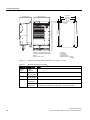
Replacing the cooling fan FSGX
Preparatory steps
● Disconnect the chassis unit from the power supply.
● Allow unimpeded access.
● Remove the protective cover.
1
2
Figure 5-4
Fan replacement, Power Module FSGX
Power Module PM240
Hardware Installation Manual, 07/2009, A5E00807525B AD
55
Service and maintenance
5.2 Replacing components
Removal
The steps for the removal procedure are numbered in accordance with the diagram.
1. Remove the retaining screws for the fan (3 screws).
2. Disconnect the supply cables (1 x "L", 1 x "N").
You can now carefully remove the fan.
CAUTION
When removing the fan, ensure that you do not damage any signal cables.
Installation
For re-installation, carry out the above steps in reverse order.
CAUTION
Carefully re-establish the plug connections and ensure that they are secure.
The screwed connections for the protective covers must only be tightened by hand.
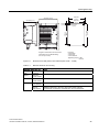
5.2.2
Replacing the cooling fan fuses and the cooling fan relay (FSGX)
Figure 5-5
Position of the cooling fan fuses ①and the fan relay ②
The cooling fan fuses and the cooling fan relay can be accessed after removing the front
cover of the Power Module FSGX.
56
Power Module PM240
Hardware Installation Manual, 07/2009, A5E00807525B AD
Service and maintenance
5.2 Replacing components
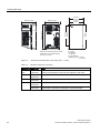
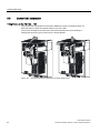
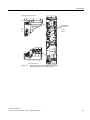
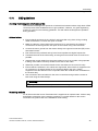
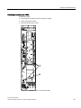
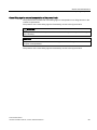
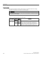
5.2.3
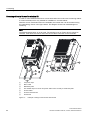
Power block replacement (FSGX)
Figure 5-6
Power block replacement, PM240 FSGX
Power Module PM240
Hardware Installation Manual, 07/2009, A5E00807525B AD
57
Service and maintenance
5.2 Replacing components
Preparatory steps
● Disconnect the built-in unit from the power supply.
● Allow unimpeded access to the power block.
● Remove the protective cover.
Removal
The steps for the removal procedure are numbered in accordance with the diagram.
1. Unscrew the connection to the outgoing motor section (3 screws on the right side).
Loose the 3 screws on the left side and turn the connection straps up.
2. Unscrew the connection to the line supply (3 screws).
3. Remove the retaining screws at the top (2 screws).
4. Remove the retaining screws at the bottom (2 screws).
5. Remove the Control Unit. If necessary, remove the communication plugs and terminal
wiring.
6. Disconnect the connectors for the fiber optic cables (3 plugs) and release the cable
connection for the signal cables (2 connectors).
Remove the IPD module by loosening two curled screws. The IPD module remains
connected to the current sensor cables.
7. Disconnect the plug for the thermocouple.
8. Unscrew the two retaining screws for the fan and attach the tool for de-installing the
power block at this position.
You can now remove the power block.
CAUTION
When removing the power block, ensure that you do not damage any signal cables.
Installation steps
For installation, carry out the above steps in reverse order.
CAUTION
The connectors of the fiber-optic cables have to be mounted on their original plug-in
position. The fiber-optic cables and the plug sockets are labelled accordingly (U11, U21,
U31).
Carefully establish the plug connections and ensure that they are secure.
The screwed union connections for the protective covers must only be tightened by hand.
58
Power Module PM240
Hardware Installation Manual, 07/2009, A5E00807525B AD
Service and maintenance
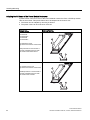
5.2 Replacing components
Crane lifting lugs for secure transportation of the power block
The power blocks are fitted with crane lifting lugs for transportation on a lifting harness in the
context of replacement.
The positions of the crane lifting lugs are illustrated by arrows in the figures below.
WARNING
A lifting harness with vertical ropes or chains must be used to prevent any risk of damage
to the housing.
CAUTION
The power block busbars must not be used to support or secure lifting harnesses for the
purpose of transportation.
The positions of the crane lifting lugs are illustrated by arrows in the figures below.
Power Module PM240
Hardware Installation Manual, 07/2009, A5E00807525B AD
59
Service and maintenance
5.2 Replacing components
Figure 5-7
60
Crane lifting lugs of the Power Block FSGX
Power Module PM240
Hardware Installation Manual, 07/2009, A5E00807525B AD
Service and maintenance
5.2 Replacing components
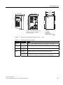
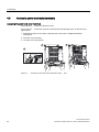
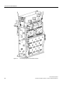
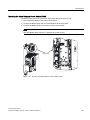
5.2.4
Control Interface Module replacement (FSGX)
Figure 5-8
Control Interface Module replacement, Power Module PM240 FSGX
Power Module PM240
Hardware Installation Manual, 07/2009, A5E00807525B AD
61
Service and maintenance
5.2 Replacing components
Preparatory steps
● Disconnect the Power Module from the power supply.
● Allow unimpeded access.
● Remove the front cover.
● Remove the Control Unit. If necessary, remove the communication plugs and terminal
wiring.
Removal
The steps for the removal procedure are numbered in accordance with the diagram.
1. Remove the two retaining screws for the Control Unit bracket.
2. Disconnect the cable from the Control Unit bracket to the CIM.
Remove the cables to the Brake Relay or Safe Brake Relay, if it is installed.
Remove carefully the Control Unit bracket.
Disconnect the connectors for the fiber optic cables (3 plugs) and release the cable
connection for the signal cables (2 connectors).
Remove the IPD module by loosening two curled screws. The IPD module remains
connected to the current sensor cables.
3. Remove the two retaining screws for the slide-in electronics unit.
When removing the slide-in electronics unit, you have to disconnect 5 further plugs one
after the other (2 at the top, 3 at the bottom).
CAUTION
When removing the electronics unit, ensure that you do not damage any signal cables.
The Control Interface Board can then be removed from the slide-in electronics unit.
CAUTION
When removing the connector of the ribbon cable, make sure that you actuate the locking
lever on the connector very carefully (e.g. with a screwdriver) otherwise the lock could be
damaged.
Installation
For re-installation, carry out the above steps in reverse order.
62
Power Module PM240
Hardware Installation Manual, 07/2009, A5E00807525B AD
Service and maintenance
5.2 Replacing components
CAUTION
The connectors of the fiber-optic cables have to be mounted on their original plug-in
position. The fiber-optic cables and the plug sockets are labelled accordingly (U11, U21,
U31).
Carefully re-establish the plug connections and ensure that they are secure.
When dealing with connectors with a lock, make sure that the locking lever is securely
engaged once connected.
The screwed connections for the protective covers must only be tightened by hand.
Power Module PM240
Hardware Installation Manual, 07/2009, A5E00807525B AD
63
6
Technical specifications
Common performance ratings of the Power Module
Table 6- 1
Performance ratings
Feature
Specification
Line operating voltage
3 AC 380 V … 480 V ± 10%
The permissible voltage depends on the operational altitude
Input frequency
47 Hz … 63 Hz
Power factor λ
0.7 ... 0.85
Overload capability for
base load (HO)
0.37 kW ... 75 kW
1.5 x Base-load output current (150% overload) for 57 s every 300 s
2 x Base-load output current (200% overload) for 3 s every 300 s
Overload capability for
base load (HO)
90 kW ... 200 kW
1.36 x Base-load output current (136% overload) for 57 s every 300 s
1.6 x Base-load output current (160% overload) for 3 s every 300 s
Overload capability for
base load (LO)
7.5 kW ... 90 kW
1.5 x Base-load output current (150% overload) for 3 s every 300 s
1.1 x Base-load output current (110% overload) for 57 s every 300 s
Overload capability for
base load (LO)
110 kW ... 250 kW
1.1 x Base-load output current (136% overload) for 59 s every 300 s
1.5 x Base-load output current (150% overload) for 1 s every 300 s
Inrush current
Less than rated input current
Pulse frequency
4 kHz standard for 0.37 kW ... 75 kW (HO)
2 kHz standard for 90 kW ... 200 kW (HO)
The pulse frequency can be changed manually in 2 kHz steps.
Increasing the pulse frequencies above standard leads to an output
current reduction.
Electromagnetic
compatibility
Optional Class A filters available according to EN 55011
Braking
DC braking, Compound braking, Dynamic braking with integrated chopper
Protection level
IP20 or IPXXB
IPXXB protection is ensured with the Power Module FSGX
(HO 132 kW … 200 kW) in conjunction with the Control Units CU240E
and CU230P-2.
Temperature range
without derating (HO)
0.37 kW ... 110 kW
0 °C … +50 °C (14 °F … 122 °F)
132 kW ... 200 kW
0 °C … +40 °C (32 °F … 104 °F)
Temperature range
without derating (LO)
0.37 kW ... 132 kW
0 °C … +40 °C (14 °F … 104 °F)
Power Module PM240
Hardware Installation Manual, 07/2009, A5E00807525B AD
65
Technical specifications
Feature
Specification
160 kW ... 250 kW
0 °C … +40 °C (32 °F … 104 °F)
Temperature range with
derating
Operational temperature up to 60° C (140° F) is possible with power
derating
Storage temperature
-40 °C … +70 °C (-40 °F … 158 °F)
Humidity
< 95% RH - non-condensing
In areas of high relative humidity, measures should be taken to ensure
that condensation does not form within or around the SINAMICS G120.
Anti-condensation heaters are commonly used to prevent the formation of
condensation.
Pollution
According pollution degree level 2
Do not install the SINAMICS G120 in an environment which contains
atmospheric pollutants such as dust and/or corrosive gases.
Shock and vibration
Do not drop the SINAMICS G120 or expose to sudden shock. Do not
install the SINAMICS G120 in an area where it is likely to be exposed to
constant vibration.
Electromagnetic radiation Do not install the SINAMICS G120 near sources of electromagnetic
radiation.
Operational altitude
without derating
0.37 kW ... 110 kW (HO)
Up to 1000 m (3300 ft) above sea level
132 kW ... 200 kW (HO)
Up to 2000 m (6500 ft) above sea level
Operational altitude with
derating
66
Higher operational altitude is possible with power derating
Power Module PM240
Hardware Installation Manual, 07/2009, A5E00807525B AD
Technical specifications
Relationship between pulse frequency and output base-load current reduction
Table 6- 2
LO base
load
Current reduction depending on pulse frequency
Output base-load current at pulse frequency of
2 kHz
4 kHz
6 kHz
8 kHz
10 kHz
12 kHz
14 kHz
16 kHz
kW
A
A
A
A
A
A
A
A
0.37
--
1.30
1.11
0.91
0.78
0.65
0.59
0.52
0.55
--
1.70
1.45
1.19
1.02
0.85
0.77
0.68
0.75
--
2.20
1.87
1.54
1.32
1.10
0.99
0.88
1.1
--
3.10
2.64
2.17
1.86
1.55
1.40
1.24
1.5
--
4.10
3.49
2.87
2.46
2.05
1.85
1.64
2.2
--
5.90
5.02
4.13
3.54
2.95
2.66
2.36
3.0
--
7.70
6.55
5.39
4.62
3.85
3.47
3.08
4.0
--
10.20
8.67
7.14
6.12
5.10
4.59
4.08
7.5
--
18.00
16.20
13.30
11.40
9.50
8.60
7.60
11.0
--
25.00
22.10
18.20
15.60
13.00
11.70
10.40
15.0
--
32.00
27.20
22.40
19.20
16.00
14.40
12.80
18.5
--
38.00
32.30
26.60
22.80
19.00
17.10
15.20
22
--
45.00
38.25
31.50
27.00
22.50
20.25
18.00
30
--
60.00
52.70
43.40
37.20
31.00
27.90
24.80
37
--
75.00
63.75
52.50
45.00
37.50
33.75
30.00
45
--
90.00
76.50
63.00
54.00
45.00
40.50
36.00
55
--
110.0
93.50
77.00
--
--
--
--
75
--
145.0
123.3
101.5
--
--
--
--
90
--
178.0
151.3
124.6
--
--
--
--
110
205.0
178.0
--
--
--
--
--
--
132
250.0
205.0
--
--
--
--
--
--
160
302.0
250.0
--
--
--
--
--
--
200
370.0
302.0
--
--
--
--
--
--
250
477.0
370.0
--
--
--
--
--
--
Power Module PM240
Hardware Installation Manual, 07/2009, A5E00807525B AD
67
Technical specifications
Operating temperature derating
The operating temperature range is shown diagramatically in the figures below:
Permissible output base load current [%]
High overload (HO)
Permissible output base load current [%]
Light overload (LO)
100
100
75
74
75
66
50
50
25
25
0
0
0
10
20
30
40
50
0
60
Ambient operating temperature [°C]
Figure 6-1
10
20
30
40
50
60
Ambient operating temperature [°C]
Current derating for temperature, FSA … FSF
Permissible output base load current [%]
High overload (HO) and light overload (LO)
100
85
75
50
25
0
0
10
20
30
40
50 55
Ambient operating temperature [°C]
Figure 6-2
68
Current derating for temperature, FSGX
Power Module PM240
Hardware Installation Manual, 07/2009, A5E00807525B AD
Technical specifications
Operational altitude derating
The figures below show the derating required according to altitude.
Permissible output base load current [%]
High overload (HO ) and light overload (LO)
Permissible output base load current [%]
High overload (HO) and light overload (LO)
100
100
90
80
90
85
80
70
70
60
60
0
1000
3300
2000
6600
3000
9800
4000
13000
0
Installation altitude above sea level [m]
[ft]
Current derating for altitude, FSA … FSF
1000
3300
2000
6600
3000
9800
4000
13000
Installation altitude above sea level [m]
[ft]
Current derating for altitude, FSGX
Permissible input voltage [%]
100
90
80
77
70
60
0
1000
3300
2000
6600
3000
9800
4000
13000
Installation altitude above sea level [m]
[ft]
Voltage derating for altitude, FSA … FSGX
Power Module PM240
Hardware Installation Manual, 07/2009, A5E00807525B AD
69
Technical specifications
Power Module specifications
CAUTION
High Overload (HO) and Light Overload (LO) input currents
The input current at the rated operating point - applies for the short-circuit voltage of the line
supply Vk = 1% referred to the rated Power Module power and a rated line supply voltage of
400 V without a line reactor. If a line reactor is used, the specified values are reduced.
NOTICE
UL certified Fuses must be used
In order that the system is in compliance with UL, UL certified fuses, circuit-breaker or self
protected combination motor controller must be used.
Table 6- 3
Order No.
Frame Sizes A, 3 AC 380 V … 480 V, ± 10%
unfiltered
6SL3224-
0BE13-7UA0
0BE15-5UA0
0BE17-5UA0
Rated power based on HOloading
kW
0.37
0.55
0.75
hp
0.5
0.75
1
Power loss
kW
0.097
0.099
0.102
Rated input current (HO)
A
1.6
2.0
2.5
Rated output current (HO)
A
1.3
1.7
2.2
Rated input current (LO)
A
1.7
2.1
2.6
Rated output current (LO)
A
1.3
1.7
2.2
Fuse
A
10
10
10
Required cooling air flow
l/s
4.8
4.8
4.8
CFM
10
10
10
Input cable /
Output cable
mm2
1.0 … 2.5
1.0 … 2.5
1.0 … 2.5
AWG
18 … 14
18 … 14
18 … 14
Weight
kg
1.2
1.2
1.2
lb
2.6
2.6
2.6
70
Power Module PM240
Hardware Installation Manual, 07/2009, A5E00807525B AD
Technical specifications
Table 6- 4
Order No.
Frame Sizes A, 3 AC 380 V … 480 V, ± 10%
unfiltered
6SL3224-
0BE21-1UA0
0BE21-5UA0
Rated power based on HOloading
kW
1.1
1.5
hp
1.5
2
Power loss
kW
0.108
0.114
Rated input current (HO)
A
3.8
4.8
Rated output current (HO)
A
3.1
4.1
Rated input current (LO)
A
3.9
4.9
Rated output current (LO)
A
3.1
4.1
Fuse
A
10
10
Required cooling air flow
l/s
4.8
4.8
CFM
10
10
mm2
1.0 … 2.5
1.0 … 2.5
AWG
18 … 14
18 … 14
kg
1.2
1.2
lb
2.6
2.6
0BE22-2AA0
0BE23-0AA0
0BE24-0AA0
0BE22-2UA0
0BE23-0UA0
0BE24-0UA0
Input cable /
Output cable
Weight
Table 6- 5
Order No.
Frame Sizes B, 3 AC 380 V … 480 V, ± 10%
filtered
6SL3224-
unfiltered
Rated power based on HOloading
kW
2.2
3
4
hp
3
4
5
Power loss
kW
0.139
0.158
0.183
Rated input current (HO)
A
7.6
10.2
13.4
Rated output current (HO)
A
5.9
7.7
10.2
Rated input current (LO)
A
7.6
10.2
13.4
Rated output current (LO)
A
5.9
7.7
10.2
Fuse
A
16
16
20
Required cooling air flow
l/s
24
24
24
CFM
50
50
50
Input cable /
Output cable
mm2
1.5 … 6.0
1.5 … 6.0
1.5 … 6.0
AWG
16 … 10
16 … 10
16 … 10
Weight
kg
4.3
4.3
4.3
lb
9.5
9.5
9.5
Power Module PM240
Hardware Installation Manual, 07/2009, A5E00807525B AD
71
Technical specifications
Table 6- 6
Order No.
Frame Sizes C, 3 AC 380 V … 480 V, ± 10%
filtered
6SL3224-
unfiltered
0BE25-5AA0
0BE27-5AA0
0BE31-1AA0
0BE25-5UA0
0BE27-5UA0
0BE31-1UA0
Rated power based on HOloading
kW
5.5
7.5
11
hp
7.5
10
15
Power loss
kW
0.240
0.297
0.396
Rated input current (HO)
A
16.7
23.7
32.7
Rated output current (HO)
A
13.2
19
26
Rated input current (LO)
A
21.9
31.5
39.4
Rated output current (LO)
A
18
25
32
Fuse
A
20
32
35
Required cooling air flow
l/s
55
55
55
CFM
120
120
120
mm2
4.0 … 10
4.0 … 10
4.0 … 10
AWG
12 … 8
12 … 8
12 … 8
Input cable /
Output cable
Weight
Table 6- 7
Order No.
filtered/
unfiltered
kg
6.5
6.5
6.5
lb
14.3
14.3
14.3
0BE31-5AA0
0BE31-8AA0
0BE32-2AA0
0BE31-5UA0
0BE31-8UA0
0BE32-2UA0
Frame Sizes D, 3 AC 380 V … 480 V, ± 10%
filtered
6SL3224-
unfiltered
Rated power based on HOloading
kW
15
18.5
22
hp
20
25
30
Power loss
filtered
kW
0.44
0.55
0.72
unfiltered
kW
0.42
0.52
0.69
A
40
46
56
Rated output current (HO)
A
32
38
45
Rated input current (LO)
A
46
53
72
Rated output current (LO)
A
38
45
60
Fuse
A
50
63
80
Required cooling air flow
l/s
55
55
55
CFM
120
120
120
mm2
10 … 35.0
10 … 35.0
10 … 35.0
AWG
7…2
7…2
7…2
Rated input current (HO)
Input cable /
Output cable
Weight
filtered
unfiltered
72
kg
16
16
16
lb
35.3
35.3
35.3
kg
13
13
13
lb
28.7
28.7
28.7
Power Module PM240
Hardware Installation Manual, 07/2009, A5E00807525B AD
Technical specifications
Table 6- 8
Order No.
Frame Sizes E, 3 AC 380 V … 480 V, ± 10%
filtered
6SL3224-
unfiltered
0BE33-0AA0
0BE33-7AA0
0BE33-0UA0
0BE33-7UA0
Rated power based on HOloading
kW
30
37
hp
40
50
Power loss
filtered
kW
1.04
1.2
unfiltered
kW
0.99
1.2
Rated input current (HO)
73
90
Rated output current (HO)
60
75
Rated input current (LO)
88
105
Rated output current (LO)
75
90
Fuse
100
125
Required cooling air flow
110
110
240
240
25.0 … 35.0
25.0 … 35.0
Input cable /
Output cable
Weight
AWG
filtered
unfiltered
Table 6- 9
Order No.
3…2
3…2
kg
23
23
lb
50.7
50.7
kg
16
16
lb
35.3
35.3
Frame Sizes F, 3 AC 380 V … 480 V, ± 10%
filtered
6SL3224-
unfiltered
0BE34-5AA0
0BE35-5AA0
0BE37-5AA0
0BE34-5UA0
0BE35-5UA0
0BE37-5UA0
Rated power based on HOloading
kW
45
55
75
hp
60
75
100
Power loss
filtered
kW
1.5
2.0
2.4
unfiltered
kW
1.4
1.9
2.3
Rated input current (HO)
108
132
169
Rated output current (HO)
90
110
145
Rated input current (LO)
129
168
204
Rated output current (LO)
110
145
178
Fuse
160
200
250
Required cooling air flow
150
150
150
Input cable /
Output cable
Weight
320
320
320
35.0 … 120
35.0 … 120
35.0 … 120
2 … 4/0
2 … 4/0
2 … 4/0
kg
52
52
52
lb
115
115
115
kg
36
36
36
lb
79.5
79.5
79.5
AWG
filtered
unfiltered
Power Module PM240
Hardware Installation Manual, 07/2009, A5E00807525B AD
73
Technical specifications
Table 6- 10
Order No.
Frame Sizes F, 3 AC 380 V … 480 V, ± 10%
unfiltered
6SL3224-
0BE38-8UA0
0BE41-1UA0
Rated power based on HOloading
kW
90
110
hp
125
150
Power loss
kW
2.4
2.5
Rated input current (HO)
A
205
235
Rated output current (HO)
A
178
205
Rated input current (LO)
A
234
284
Rated output current (LO)
A
205
250
Fuse
A
250
315
Required cooling air flow
l/s
Input cable /
Output cable
Weight
Table 6- 11
Order No.
150.0
150.0
CFM
320
320
mm2
35.0 … 120
35.0 … 120
AWG
2 … 4/0
2 … 4/0
kg
39
39
lb
90
90
0XE41-3UA0
0XE41-6UA0
0XE42-0UA0
Frame Sizes GX, 3 AC 380 V … 480 V, ± 10%
unfiltered
6SL3224-
Rated power based on HOloading
kW
132
160
200
hp
177
215
268
Power loss
kW
3.9
4.4
5.5
Rated input current (HO)
A
245
297
354
Rated output current (HO)
A
250
302
370
Rated input current (LO)
A
297
354
442
Rated output current (LO)
A
302
370
477
Fuse
A
355
400
630
Required cooling air flow
l/s
360
360
360
CFM
760
760
760
Input cable /
Output cable
mm2
95 ... 240
120 ... 240
185 ... 240
AWG
3/0 ... 600
4/0 ... 600
6/0 ... 600
Weight
kg
176
176
176
lb
388
388
388
74
Power Module PM240
Hardware Installation Manual, 07/2009, A5E00807525B AD
7
Accessories
Which accessory is available for which Power Module?
Accessory
available (✓) or not available (-) for Power Module …
FSA
0.37 k
W
...
1.5 kW
FSB
2.2 kW
...
4 kW
FSC
5.5 kW
...
11 kW
FSD
15 kW
...
22 kW
FSE
30 kW
...
37 kW
FSF
45 kW
...
110 kW
FSGX
132 kW
...
200 kW
Line reactor
✓
✓
✓
✓
✓
✓
✓
Line filter
✓
✓
✓
✓
✓
✓
✓
Output reactor
✓
✓
✓
✓
✓
✓
✓
Sine-wave filter
✓
✓
✓
✓
✓
✓
✓
Brake chopper
Integrated in the Power Module
✓
Braking resistor
✓
✓
✓
✓
✓
✓
✓
Brake Relay and Safe Brake
Relay
✓
✓
✓
✓
✓
✓
✓
DIN rail mounting kit
✓
✓
-
-
-
-
-
Screen termination kit
✓
✓
✓
✓
✓
✓
-
Power Module PM240
Hardware Installation Manual, 07/2009, A5E00807525B AD
75
Accessories
7.1 Reactor and filter
7.1
Reactor and filter
Line reactor
The purpose of a line reactor is to reduce line-side harmonic currents and harmonic effects.
This applies particularly in the case of weak power supplies (network short-circuit power uK
> 1 %).
Line filter
The Power Module complies with a higher radio interference class when an additional line
filter is used.
Output reactor
Output reactors reduce the voltage loading on the motor windings. At the same time, the
capacitive charge/discharge currents, which place an additional load on the power section
when long motor cables are used, are reduced.
Sine-wave filter
The sine-wave filter is designed to limit the rate of rise of voltage and the capacitive charge
or discharge currents which usually occur with inverter operation.
76
Power Module PM240
Hardware Installation Manual, 07/2009, A5E00807525B AD
Accessories
7.1 Reactor and filter
Connecting reactor and filter to the Power Module
The following drawings show the connecting order of the power components. Shielded
cables are necessary if a line filter (external or integrated) is used.
Line fuses and contactor have to be installed between line reactor input and mains system.
/LQH
/LQH
8 9 : 3(
8 9 : 3(
/LQHUHDFWRU
/LQHUHDFWRU
8 9 : 3(
L1
/
L3
8 9 : 3(
3(
/LQHILOWHU
H[WHUQDO
L1’
/ಬ
8 9
L3’ 3(ಬ
: 3(
3RZHU0RGXOH
8 9
/
L3
L1’
/ಬ
L3’ 3(ಬ
: 3(
8 9
0RXQWLQJ
VXUIDFHRU
FDELQHWZDOO
3(
: 3(
3RZHU0RGXOH
8 9
: 3(
0RXQWLQJ
VXUIDFHRU
FDELQHWZDOO
8 9 : 3(
8 9 : 3(
6LQHZDYHILOWHU
2XWSXWUHDFWRU
8 9 : 3(
8 9 : 3(
8 9 :
0RWRU
L1
/LQHILOWHU
H[WHUQDO
8 9 :
3(
0
Connecting power components with output
reactor
Power Module PM240
Hardware Installation Manual, 07/2009, A5E00807525B AD
0RWRU
3(
0
Connecting power components with sinewave filter
77
Accessories
7.1 Reactor and filter
Mounting base components
Many system components for the Power Modules are designed as base components, that is,
the component is mounted on the cabinet wall and the Power Module above it in a spacesaving construction. Up to two base components can be mounted above one another. Every
further system component has to be mounted laterally.
%DVHFRPSRQHQWV
3RZHU0RGXOH
3RVLWLRQ 3RVLWLRQ
0RXQWLQJ
VXUIDFHRU
FDELQHWZDOO
Figure 7-1
Mounting base components
Table 7- 1
Possible combinations of two base components
Power Module frame size
FSA and FSB
0.37 kW … 4 kW
Base component on …
… position 1
… position 2
Line reactor
Output reactor
Sine-wave filter
Braking resistor
Line filter
Line reactor
Output reactor
Sine-wave filter
Braking resistor
FSC
5.5 kW … 11 kW
Line reactor
Output reactor
Sine-wave filter
Line filter
Line reactor
Output reactor
Sine-wave filter
78
Power Module PM240
Hardware Installation Manual, 07/2009, A5E00807525B AD
Accessories
7.1 Reactor and filter
7.1.1
Line reactor
Installing the line reactor as base component
The line reactors for PM240 Power Modules of frame sizes FSA to FSE (0.37 kW … 37 kW)
are designed as base components. The line reactor is attached to the mounting surface and
the Power Module is mounted directly on the line reactor. The cables to the Power Module
are already connected to the line reactor. The line reactor is connected to the line supply
through terminals.
/
/
/
3(
/LQH
3RZHU0RGXOH
/LQH
UHDFWRU
0RWRU
Figure 7-2
0
8
9
:
3(
8
9
:
3(
0RXQWLQJ
VXUIDFHRU
FDELQHWZDOO
&RQQHFWLRQ
FDEOH
Connecting the line reactor as base component
The overall and mounting dimensions of the line reactor are written in the technical
specifications. For more information see
http://support.automation.siemens.com/WW/view/en/23623183
Power Module PM240
Hardware Installation Manual, 07/2009, A5E00807525B AD
79
Accessories
7.1 Reactor and filter
Installing the line reactor as lateral mounting component
The line reactors for PM240 Power Modules of frame sizes FSF and FSGX
(45 kW … 200 kW) have to be mounted laterally.
/LQH
8 9 : 3(
/LQHUHDFWRU
8 9 : 3(
8 9
: 3(
3RZHU0RGXOH
8 9
: 3(
8 9 :
0RWRU
Figure 7-3
0RXQWLQJ
VXUIDFHRU
FDELQHWZDOO
3(
0
Connecting the line reactor as lateral mounting component
Technical specifications of the line reactors
The major electrical specification of the line reactors is the same as for the suitable Power
Module. This applies to:
● line voltage
● line frequency
● rated current
The admissible ambient conditions of the line reactors are the same as for the suitable
Power Module. This applies to:
● storage and transport temperature
● operating temperature
● relative humidity
● shock and vibration load
80
Power Module PM240
Hardware Installation Manual, 07/2009, A5E00807525B AD
Accessories
7.1 Reactor and filter
Table 7- 2
Technical specifications of the line reactors (table 1 of 6)
Feature
Suitable for Power Module with rated power (HO) of
0.37 kW ... 0.55 kW
0.75 kW ... 1.1 kW
1.5 kW
FSA
MLFB of the line reactor
6SE6400-3CC00-2AD3
6SE6400-3CC00-4AD3
6SE6400-3CC00-6AD3
MLFB of the suitable Power
Module
6SL3224-0BE13-7UA0
6SL3224-0BE15-5UA0
6SL3224-0BE17-5UA0
6SL3224-0BE21-1UA0
6SL3224-0BE21-5UA0
11.5 mH
6.3 mH
3.2 mH
12.5/15 W
7.5/9 W
Inductance
Power loss at 50/60 Hz
6/7 W
Line connection
Screw terminals 1 … 2.5 mm²
Connection to Power
Module
Cable, 380 mm length
Degree of protection
IP20
Overall dimensions
Width
Height
Depth
75.5 mm
200 mm
50 mm
Fixing dimensions
Width
Height
187 mm
56 mm
Fixing screw
4 × M4
Weight
0.6 kg
0.8 kg
Possible as base
component
Table 7- 3
0.6 kg
yes
Technical specifications of the line reactors (table 2 of 6)
Feature
Suitable for Power Module with rated power (HO) of
2.2 kW ... 3 kW
4 kW
5.5 kW ... 7.5 kW
FSB
FSC
MLFB of the line reactor
6SL3203-0CD21-0AA0
6SL3203-0CD21-4AA0
6SL3203-0CD22-2AA0
MLFB of the suitable Power
Module
6SL3224-0BE22-2 . A0
6SL3224-0BE23-0 . A0
6SL3224-0BE24-0 . A0
6SL3224-0BE25-5 . A0
6SL3224-0BE27-5 . A0
Inductance
2.2 mH
1.3 mH
0.56 mH
Power loss at 50/60 Hz
9/11 W
27/32 W
98/118 W
Line connection
Connection to Power
Module
Screw terminals 1.5 … 6 mm²
Screw terminals
2.5 … 10 mm²
Cable, 460 mm length
Cable, 490 mm length
Degree of protection
Overall dimensions
Width
Height
Depth
Power Module PM240
Hardware Installation Manual, 07/2009, A5E00807525B AD
IP20
153 mm
290 mm
70 mm
189 mm
371 mm
50 mm
81
Accessories
7.1 Reactor and filter
Feature
Suitable for Power Module with rated power (HO) of
2.2 kW ... 3 kW
4 kW
5.5 kW ... 7.5 kW
FSB
FSC
Fixing dimensions
Width
Height
120 mm
200 mm
156 mm
232 mm
Fixing screw
4 × M4
4 × M5
Weight
3.4 kg
3.4 kg
Possible as base
component
Table 7- 4
5.2 kg
yes
Technical specifications of the line rectors (table 3 of 6)
Feature
Suitable for Power Module with rated power (HO) of
11 kW
15 kW ... 18.5 kW
22 kW
FSC
FSD
MLFB of the line reactor
6SL3203-0CD23-5AA0
6SL3203-0CJ24-5AA0
6SL3203-0CD25-3AA0
MLFB of the suitable Power
Module
6SL3224-0BE31-1 . A0
6SL3224-0BE31-5 . A0
6SL3224-0BE31-8 . A0
6SL3224-0BE32-2 . A0
Inductance
0.28 mH
0.41 mH
0.29 mH
Power loss at 50/60 Hz
37/44 W
Line connection
Connection to Power
Module
90/115 W
Screw terminals 16 mm²
Cable, 490 mm length
Degree of protection
Cable, 700 mm length
IP20
Overall dimensions
Width
Height
Depth
189 mm
371 mm
50 mm
275 mm
455 mm
84 mm
Fixing dimensions
Width
Height
156 mm
232 mm
235 mm
421 mm
Fixing screw
4 × M5
4 × M8
Weight
5.9 kg
13 kg
Possible as base
component
82
yes
Power Module PM240
Hardware Installation Manual, 07/2009, A5E00807525B AD
Accessories
7.1 Reactor and filter
Table 7- 5
Technical specifications of the line rectors (table 4 of 6)
Feature
Suitable for Power Module with rated power (HO) of
30 kW ... 37 kW
FSE
MLFB of the line reactor
6SL3203-0CJ28-6AA0
MLFB of the suitable Power
Module
6SL3224-0BE33-0 . A0
6SL3224-0BE33-7 . A0
Inductance
0.22 mH
Power loss at 50/60 Hz
Line connection
170/215 W
Screw terminals 50 mm²
Connection to Power
Module
Cable, 700 mm length
Degree of protection
IP20
Overall dimensions
Width
Height
Depth
275 mm
577 mm
94 mm
Fixing dimensions
Width
Height
235 mm
544 mm
Fixing screw
4 × M8
Weight
13 kg
Possible as base
component
Table 7- 6
yes
Technical specifications of the line rectors (table 5 of 6)
Feature
Suitable for Power Module with rated power (HO) of
45 kW ... 55 kW
75 kW
90 kW
MLFB of the line reactor
6SE6400-3CC11-2FD0
6SE6400-3CC11-7FD0
6SL3000-0CE32-3AA0
MLFB of the suitable Power
Module
6SL3224-0BE34-5 . A0
6SL3224-0BE35-5 . A0
6SL3224-0BE37-5 . A0
6SL3224-0BE38-8UA0
0.15 mH
90 µH
76 µH
280/360 W
280/360 W
240/270 W
FSF
Inductance
Power loss at 50/60 Hz
Line connection
Flat connector for M8 cable lug
Flat connector for M10 cable
lug
Connection to Power
Module
Flat connector for M8 cable lug
Flat connector for M10 cable
lug
Degree of protection
Overall dimensions
Width
Height
Depth
Power Module PM240
Hardware Installation Manual, 07/2009, A5E00807525B AD
IP00
240 mm
228 mm
141 mm
270 mm
200 mm
248 mm
83
Accessories
7.1 Reactor and filter
Feature
Suitable for Power Module with rated power (HO) of
45 kW ... 55 kW
75 kW
90 kW
FSF
Fixing dimensions
Width
Depth
95 mm
185 mm
101 mm
200 mm
Fixing screw
4 × M8
Weight
25 kg
24 kg
Possible as base
component
Table 7- 7
no
Technical specifications of the line rectors (table 6 of 6)
Feature
Suitable for Power Module with rated power (HO) of
110 kW
132 kW
FSF
160 kW and 200 kW
FSGX
MLFB of the line reactor
6SL3000-0CE32-8AA0
6SL3000-0CE33-3AA0
6SL3000-0CE35-1AA0
MLFB of the suitable Power
Module
6SL3224-0BE41-1UA0
6SL3224-0XE41-3UA0
6SL3224-0XE41-6UA0
6SL3224-0XE42-0UA0
Inductance
Power loss at 50/60 Hz
62 µH
52 µH
42 µH
210/250 W
270 W
365 W
Line connection
Flat connector for M10 cable lug
Flat connector for M12 cable
lug
Connection to Power
Module
Flat connector for M10 cable lug
Flat connector for M12 cable
lug
Degree of protection
IP00
Overall dimensions
Width
Height
Depth
270 mm
200 mm
248 mm
270 mm
248 mm
200 mm
300 mm
269 mm
212,5 mm
Fixing dimensions
Width
Depth
101 mm
200 mm
200 mm
101 mm
224 mm
118 mm
Fixing screw
Weight
Possible as base
component
84
4 × M8
24 kg
28 kg
38 kg
no
Power Module PM240
Hardware Installation Manual, 07/2009, A5E00807525B AD
Accessories
7.1 Reactor and filter
7.1.2
Line filter
Installing the line filter as base component
The line filters associated with the Power Modules of a rated power (HO) up to 11 kW are
designed as base components. The line filter is attached to the mounting surface and the
Power Module is mounted directly on the line filter.
The cables to the Power Module are already connected to the line filter. The line filter is
connected to the line supply through terminals.
/
/
/
3(
/LQH
3RZHU0RGXOH
/LQHILOWHU
0RWRU
Figure 7-4
0
8
9
:
3(
8
9
:
3(
0RXQWLQJ
VXUIDFHRU
FDELQHWZDOO
&RQQHFWLRQ
FDEOH
Connecting the line filter as base component
The overall and mounting dimensions of the line filter are written in the technical
specifications.
Power Module PM240
Hardware Installation Manual, 07/2009, A5E00807525B AD
85
Accessories
7.1 Reactor and filter
Installing the line filter as lateral mounting component
The line filters for Power Modules with a rated power (HO) of more than 11 kW and line
filters from third party suppliers have to be mounted laterally.
/LQH
L1
/
L3
3(
L1’
/ಬ
L3’ 3(ಬ
/LQHILOWHU
8 9
: 3(
3RZHU0RGXOH
8 9
: 3(
8 9 :
0RWRU
Figure 7-5
0RXQWLQJ
VXUIDFHRU
FDELQHWZDOO
3(
0
Connecting the line filter as lateral component
Shielded cables must be used from the line filter to the motor. The filter has to be installed as
close as possible to the line entry of the cubicle.
Technical specifications of the line filters
The major electrical specification of the line filters is the same as for the suitable Power
Module. This applies to:
● line voltage
● line frequency
● rated current
The admissible ambient conditions of the line filters are the same as for the suitable Power
Module. This applies to:
● storage and transport temperature
● operating temperature
● relative humidity
● shock and vibration load
86
Power Module PM240
Hardware Installation Manual, 07/2009, A5E00807525B AD
Accessories
7.1 Reactor and filter
Table 7- 8
Technical specifications of the line filters class A
Feature
Suitable for Power Module with rated power (HO) of
0.37 kW ... 1.5 kW
90 kW ... 110 kW
132 kW ... 200 kW
FSA
FSF
FSGX
MLFB of the line filter
6SE6400-2FA00-6AD0
6SL3203-0BE32-5AA0
6SL3000-0BE36-0AA0
MLFB of the suitable Power
Module
6SL3224-0BE13-7UA0
6SL3224-0BE15-5UA0
6SL3224-0BE17-5UA0
6SL3224-0BE21-1UA0
6SL3224-0BE21-5UA0
6SL3224-0BE38-8UA0
6SL3224-0BE41-1UA0
6SL3224-0XE41-3UA0
6SL3224-0XE41-6UA0
6SL3224-0XE42-0UA0
0.5 ... 1.5 W
60 W
55 W
Screw terminals 2.5 mm²
On housing via M8 screw
stud
M10 connecting lugs
Connection to Power
Module
Cable, 400 mm length
On housing via M8 screw
stud
M10 connecting lugs
Degree of protection
IP20
Overall dimensions
Width
Height
Depth
73 mm
200 mm
42.5 mm
240 mm
360 mm
116 mm
400 mm
265 mm
140 mm
Fixing dimensions
Width
Height
56 mm
187 mm
210 mm
220 mm
240 mm
250 mm
Fixing screw
4 × M4
4 × M8
4 × M10
Weight
0.6 kg
12.4 kg
Power loss at 50 Hz
Line connection
Possible as base
component
Table 7- 9
IP00
yes
19 kg
no
Technical specifications of the line filters class B
Feature
Suitable for Power Module with rated power (HO) of
0.37 kW ... 1.5 kW
2.2 kW ... 4 kW
5.5 kW ... 11 kW
FSA
FSB
FSC
MLFB of the line filter
6SE6400-2FB00-6AD0
6SL3203-0BE21-6SA0
6SL3203-0BD23-8SA0
MLFB of the suitable Power
Module
6SL3224-0BE13-7UA0
6SL3224-0BE15-5UA0
6SL3224-0BE17-5UA0
6SL3224-0BE21-1UA0
6SL3224-0BE21-5UA0
6SL3224-0BE22-2AA0
6SL3224-0BE23-0AA0
6SL3224-0BE24-0AA0
6SL3224-0BE25-5AA0
6SL3224-0BE27-5AA0
6SL3224-0BE31-1AA0
0.5 W ... 1.5 W
2.0 W ... 4.0 W
7.5 W ... 15 W
Screw terminals 2.5 mm²
Screw terminals 2.5 mm²
Screw terminals 4 mm²
Cable, 400 mm length
Cable, 400 mm length
Cable, 400 mm length
Power loss at 50 Hz
Line connection
Connection to Power
Module
Degree of protection
Power Module PM240
Hardware Installation Manual, 07/2009, A5E00807525B AD
IP20
87
Accessories
7.1 Reactor and filter
Feature
Suitable for Power Module with rated power (HO) of
0.37 kW ... 1.5 kW
2.2 kW ... 4 kW
5.5 kW ... 11 kW
FSA
FSB
FSC
Overall dimensions
Width
Height
Depth
73 mm
200 mm
42.5 mm
153 mm
296 mm
50 mm
190 mm
362 mm
55 mm
Fixing dimensions
Width
Height
56 mm
187 mm
120 mm
200 mm
156 mm
232 mm
Fixing screw
Weight
Possible as base
component
88
4 × M4
0.5 kg
4 × M5
1.5 kg
2.3 kg
yes
Power Module PM240
Hardware Installation Manual, 07/2009, A5E00807525B AD
Accessories
7.1 Reactor and filter
7.1.3
Output reactor
Installing the output reactor as base component
The output reactors for Power Modules with a rated power (HO) up to 11 kW are designed
as base components. The output reactor is attached to the mounting surface and the Power
Module is mounted directly on the output reactor.
The cables to the Power Module are already connected to the output reactor. The output
reactor is connected to the motor through terminals.
3RZHU0RGXOH
2XWSXW
UHDFWRU
8
9
:
3(
8
9
:
3(
8
9
:
3(
0RXQWLQJ
VXUIDFHRU
FDELQHWZDOO
/LQH
&RQQHFWLRQ
FDEOH
0
0RWRU
Figure 7-6
Connecting the output reactor as base component
The overall and mounting dimensions of the output reactor are written in the technical
specifications.
Power Module PM240
Hardware Installation Manual, 07/2009, A5E00807525B AD
89
Accessories
7.1 Reactor and filter
Installing the output reactor as lateral mounting component
The output reactors for Power Modules with a rated power (HO) of more than 11 kW have to
be mounted laterally.
/LQH
8 9
: 3(
3RZHU0RGXOH
8 9
: 3(
0RXQWLQJ
VXUIDFHRU
FDELQHWZDOO
8 9 : 3(
2XWSXWUHDFWRU
8 9 : 3(
8 9 :
0RWRU
Figure 7-7
3(
0
Connecting the output reactor as lateral component
For more information see http://support.automation.siemens.com/WW/view/en/22103628
Technical specifications of the output reactors
The major electrical specification of the output reactors is the same as for the suitable Power
Module. This applies to:
● voltage
● rated current
The maximum permissible output frequency of the Power Module is 150 Hz when an output
reactor is used – the pulse frequency must not exceed 4 kHz.
The admissible ambient conditions of the output reactors are the same as for the suitable
Power Module. This applies to:
● storage and transport temperature
● operating temperature
● relative humidity
● shock and vibration load
90
Power Module PM240
Hardware Installation Manual, 07/2009, A5E00807525B AD
Accessories
7.1 Reactor and filter
Table 7- 10
Technical specifications of the output reactors (table 1 of 6)
Feature
Suitable for Power Module with rated power (HO) of
0.37 kW ... 1.5 kW
2.2 kW … 4 kW
5.5 kW … 11 kW
FSA
FSB
FSC
MLFB of the line reactor
6SE6400-3TC00-4AD2
6SL3202-0AE21-0CA0
6SL3202-0AJ23-2CA0
MLFB of the suitable Power
Module
6SL3224-0BE13-7UA0
6SL3224-0BE15-5UA0
6SL3224-0BE17-5UA0
6SL3224-0BE21-1UA0
6SL3224-0BE21-5UA0
6SL3224-0BE22-2 . A0
6SL3224-0BE23-0 . A0
6SL3224-0BE24-0 . A0
6SL3224-0BE25-5 . A0
6SL3224-0BE27-5 . A0
6SL3224-0BE31-1 . A0
5W
20 W
60 W
Power loss at 50/60 Hz
Motor connection
Connection to Power
Module
Screw terminals 6 mm²
Cable, 300 mm length
Cable, 400 mm length
Degree of protection
Cable, 350 mm length
IP00
Overall dimensions
Width
Height
Depth
75.5 mm
200 mm
110 mm
154 mm
270 mm
70 mm
189 mm
334 mm
80 mm
Fixing dimensions
Width
Height
56 mm
187 mm
120 mm
200 mm
156 mm
232 mm
Fixing screw
4 × M4
Weight
4 × M5
2 kg
4.5 kg
Possible as base
component
Table 7- 11
9 kg
yes
Technical specifications of the output reactors (table 2 of 6)
Feature
Suitable for Power Module with rated power (HO) of
15 kW
18.5 kW
22 kW
FSD
MLFB of the line reactor
6SE6400-3TC05-4DD0
6SE6400-3TC03-8DD0
6SE6400-3TC05-4DD0
MLFB of the suitable Power
Module
6SL3224-0BE31-5 . A0
6SL3224-0BE31-8 . A0
6SL3224-0BE32-2 . A0
200 W
200 W
Power loss at 50/60 Hz
200 W
Motor connection
Flat connector for M6 cable lug
Connection to Power
Module
Flat connector for M6 cable lug
Degree of protection
IP00
Overall dimensions
Width
Height
Depth
225 mm
210 mm
150 mm
Power Module PM240
Hardware Installation Manual, 07/2009, A5E00807525B AD
91
Accessories
7.1 Reactor and filter
Feature
Suitable for Power Module with rated power (HO) of
15 kW
18.5 kW
22 kW
FSD
Fixing dimensions
Width
Height
70 mm
176 mm
94 mm
176 mm
Fixing screw
4 × M6
Weight
10.5 kg
16 kg
Possible as base
component
Table 7- 12
70 mm
176 mm
10.5 kg
no
Technical specifications of the output reactors (table 3 of 6)
Feature
Suitable for Power Module with rated power (HO) of
30 kW
37 kW
45 kW
FSE
FSF
MLFB of the line reactor
6SE6400-3TC08-0ED0
6SE6400-3TC07-5ED0
6SE6400-3TC14-5FD0
MLFB of the suitable Power
Module
6SL3224-0BE33-0 . A0
6SL3224-0BE33-7 . A0
6SL3224-0BE34-5 . A0
170 W
270 W
Power loss at 50/60 Hz
470 W
Motor connection
Flat connector for M6 cable lug
Flat connector for M8 cable
lug
Connection to Power
Module
Flat connector for M6 cable lug
Flat connector for M8 cable
lug
Degree of protection
IP00
Overall dimensions
Width
Height
Depth
225 mm
210 mm
150 mm
270 mm
248 mm
209 mm
350 mm
321 mm
288 mm
Fixing dimensions
Width
Height
70 mm
176 mm
101 mm
200 mm
138 mm
264 mm
Fixing screw
4 × M6
Weight
10.5 kg
Possible as base
component
92
4 × M8
25 kg
52 kg
no
Power Module PM240
Hardware Installation Manual, 07/2009, A5E00807525B AD
Accessories
7.1 Reactor and filter
Table 7- 13
Technical specifications of the output reactors (table 4 of 6)
Feature
Suitable for Power Module with rated power (HO) of
55 kW
75 kW
90 kW
FSF
MLFB of the line reactor
6SE6400-3TC15-4FD0
6SE6400-3TC14-5FD0
6SL3000-2BE32-1AA0
MLFB of the suitable Power
Module
6SL3224-0BE35-5 . A0
6SL3224-0BE37-5 . A0
6SL3224-0BE38-8UA0
250 W
470 W
490 W
Power loss at 50/60 Hz
Motor connection
Flat connector for M8 cable lug
Flat connector for M10 cable
lug
Connection to Power
Module
Flat connector for M8 cable lug
Flat connector for M10 cable
lug
Degree of protection
IP00
Overall dimensions
Width
Height
Depth
270 mm
248 mm
209 mm
350 mm
321 mm
288 mm
300 mm
285 mm
257 mm
Fixing dimensions
Width
Height
101 mm
200 mm
138 mm
264 mm
163 mm
224 mm
Fixing screw
4 × M8
Weight
52 kg
Possible as base
component
Table 7- 14
no
Technical specifications of the output reactors (table 5 of 6)
Feature
Suitable for Power Module with rated power (HO) of
110 kW
132 kW
FSF
160 kW
FSGX
MLFB of the line reactor
6SL3000-2BE32-6AA0
6SL3000-2BE33-2AA0
6SL3000-2BE33-8AA0
MLFB of the suitable Power
Module
6SL3224-0BE41-1UA0
6SL3224-0XE41-6UA0
6SL3224-0XE42-0UA0
500 W
470 W
500 W
Motor connection
Flat connector for M10 screw
Flat connector for M10 screw
Flat connector for M10 screw
Connection to Power
Module
Flat connector for M10 screw
Flat connector for M10 screw
Flat connector for M10 screw
Power loss at 50/60 Hz
Degree of protection
IP00
Overall dimensions
Width
Height
Depth
300 mm
315 mm
277 mm
300 mm
285 mm
257 mm
300 mm
285 mm
277 mm
Fixing dimensions
Width
Height
183 mm
224 mm
163 mm
224 mm
183 mm
224 mm
Power Module PM240
Hardware Installation Manual, 07/2009, A5E00807525B AD
93
Accessories
7.1 Reactor and filter
Feature
Suitable for Power Module with rated power (HO) of
110 kW
132 kW
FSF
FSGX
Fixing screw
4 × M8
Weight
52 kg
66 kg
Possible as base
component
Table 7- 15
160 kW
73 kg
no
Technical specifications of the output reactors (table 6 of 6)
Feature
Suitable for Power Module with rated power (HO) of
200 kW
FSGX
MLFB of the line reactor
6SL3000-2BE35-0AA0
MLFB of the suitable Power
Module
6SL3224-0XE41-3UA0
Power loss at 50 Hz
500 W
Motor connection
Flat connector for M12 screw
Connection to Power
Module
Flat connector for M12 screw
Degree of protection
IP00
Overall dimensions
Width
Height
Depth
300 mm
365 mm
277 mm
Fixing dimensions
Width
Height
183 mm
224 mm
Fixing screw
Weight
Possible as base
component
94
M10
100 kg
no
Power Module PM240
Hardware Installation Manual, 07/2009, A5E00807525B AD
Accessories
7.1 Reactor and filter
7.1.4
Sine-wave filter
Installing the sine-wave filter as base component
The sine-wave filters for Power Modules with a rated power (HO) up to 11 kW are designed
as base components. The sine-wave filter is attached to the mounting surface and the Power
Module is mounted directly on the sine-wave filter. The cables to the Power Module are
already connected to the sine-wave filter. The sine-wave filter is connected to the motor
through terminals.
3RZHU0RGXOH
6LQHZDYH
ILOWHU
8
9
:
3(
8
9
:
3(
8
9
:
3(
0RXQWLQJ
VXUIDFHRU
FDELQHWZDOO
/LQH
&RQQHFWLRQ
FDEOH
0
0RWRU
Figure 7-8
Connecting the sine-wave filter as base component
The overall and mounting dimensions of the sine-wave filter are written in the technical
specifications.
Power Module PM240
Hardware Installation Manual, 07/2009, A5E00807525B AD
95
Accessories
7.1 Reactor and filter
Installing the sine-wave filter as lateral mounting component
The sine-wave filter for Power Modules with a rated power (HO) of more than 11 kW has to
be mounted laterally.
/LQH
8 9
: 3(
3RZHU0RGXOH
8 9
: 3(
0RXQWLQJ
VXUIDFHRU
FDELQHWZDOO
8 9 : 3(
6LQHZDYHILOWHU
8 9 : 3(
8 9 :
0RWRU
Figure 7-9
3(
0
Connecting the sine-wave filter as lateral component
For more information see http://support.automation.siemens.com/WW/view/en/29522775
Technical specifications of the sine-wave filter
The major electrical specification of the sine-wave filter is the same as for the suitable Power
Module. This applies to:
● voltage
● current
The maximum permissible output frequency of the Power Module is 150 Hz when a sinewave filter is used – the pulse frequency must not exceed 8 kHz.
The admissible ambient conditions of the sine-wave filter are the same as for the suitable
Power Module. This applies to:
● storage and transport temperature
● operating temperature
● relative humidity
● shock and vibration load
96
Power Module PM240
Hardware Installation Manual, 07/2009, A5E00807525B AD
Accessories
7.1 Reactor and filter
Table 7- 16
Technical specifications of the sine-wave filters (table 1 of 5)
Feature
Suitable for Power Module with rated power (HO) of
0.37 kW ... 0.75 kW
1.1 kW … 1.5 kW
2.2 kW …3 kW
FSA
FSB
MLFB of the sine-wave
filter
6SL3202-0AE20-3SA0
6SL3202-0AE20-6SA0
6SL3202-0AE21-1SA0
MLFB of the suitable Power
Module
6SL3224-0BE13-7UA0
6SL3224-0BE15-5UA0
6SL3224-0BE17-5UA0
6SL3224-0BE21-1UA0
6SL3224-0BE21-5UA0
6SL3224-0BE22-2 . A0
6SL3224-0BE23-0 . A0
10 W
20 W
22 W
Power loss at 50 Hz
dv/dt limiting
≤ 500 V/µs
Motor connection
Screw terminals 6 mm²
Connection to Power
Module
Cable, 500 mm length
Degree of protection
IP20
Overall dimensions
Width
Height
Depth
75.5 mm
200 mm
110 mm
Installation clearance
Top
Bottom
Side
Fixing dimensions
Width
Height
153 mm
270 mm
100 mm
100 mm
100 mm
100 mm
56 mm
187 mm
56 mm
187 mm
Fixing screw
4 × M4
Weight
2.6 kg
4 × M4
3.0 kg
Possible as base
component
Table 7- 17
133 mm
258 mm
6.0 kg
yes
Technical specifications of the sine-wave filters (table 2 of 5)
Feature
Suitable for Power Module with rated power (HO) of
4 kW
5.5 kW
7.5 kW … 11 kW
FSB
FSC
MLFB of the sine-wave
filter
6SL3202-0AE21-4SA0
6SL3202-0AE22-0SA0
6SL3202-0AE23-3SA0
MLFB of the suitable Power
Module
6SL3224-0BE24-0 . A0
6SL3224-0BE25-5 . A0
6SL3224-0BE27-5 . A0
6SL3224-0BE31-1 . A0
dv/dt limiting
Power loss at 50 Hz
≤ 500 V/µs
36 W
40 W
65 W
Motor connection
Screw terminals 6 mm²
Screw terminals 10 mm²
Connection to Power
Module
Cable, 500 mm length
Cable, 500 mm length
Degree of protection
Power Module PM240
Hardware Installation Manual, 07/2009, A5E00807525B AD
IP20
97
Accessories
7.1 Reactor and filter
Feature
Suitable for Power Module with rated power (HO) of
4 kW
Overall dimensions
Width
Height
Depth
5.5 kW
FSB
FSC
153 mm
270 mm
100 mm
189 mm
336 mm
140 mm
Installation clearance
Top
Bottom
Side
Fixing dimensions
Width
Height
100 mm
100 mm
100 mm
133 mm
258 mm
Fixing screw
4 × M4
Weight
10.0 kg
167 mm
323 mm
4 × M5
12.0 kg
Possible as base
component
Table 7- 18
7.5 kW … 11 kW
23.0 kg
yes
Technical specifications of the sine-wave filters (table 3 of 5)
Feature
Suitable for Power Module with rated power (HO) of
15 kW … 18.5 kW
22 kW
30 kW … 37 kW
FSD
FSE
MLFB of the sine-wave
filter
6SL3202-0AE24-6SA0
6SL3202-0AE26-2SA0
6SL3202-0AE28-8SA0
MLFB of the suitable Power
Module
6SL3224-0BE31-5 . A0
6SL3224-0BE31-8 . A0
6SL3224-0BE32-2 . A0
6SL3224-0BE33-0 . A0
6SL3224-0BE33-7 . A0
dv/dt limiting
Power loss at 50 Hz
≤ 500 V/µs
80 W
65 W
100 W
Motor connection
Screw terminals 25 … 50 mm²
Screw terminals
25 … 95 mm²
Connection to Power
Module
Screw terminals 25 … 50 mm²
Screw terminals
25 … 95 mm²
Degree of protection
Overall dimensions
Width
Height
Depth
IP00 without terminal cover, IP20 with terminal cover
250 mm
305 mm
262 mm
250 mm
315 mm
262 mm
Installation clearance
Top
Bottom
Side
275 mm
368 mm
275 mm
100 mm
100 mm
Fixing dimensions
Width
Depth
230 mm
127 mm
250 mm
132 mm
Fixing screw
4 × M6
4 × M8
98
Power Module PM240
Hardware Installation Manual, 07/2009, A5E00807525B AD
Accessories
7.1 Reactor and filter
Feature
Suitable for Power Module with rated power (HO) of
15 kW … 18.5 kW
22 kW
30 kW … 37 kW
FSD
Weight
24 kg
FSE
34 kg
Possible as base
component
Table 7- 19
45 kg
no
Technical specifications of the sine-wave filters (table 4 of 5)
Feature
Suitable for Power Module with rated power (HO) of
45 kW … 55 kW
75 kW
90 kW … 110 kW
FSF
MLFB of the sine-wave
filter
6SL3202-0AE31-5SA0
6SL3202-0AE31-8SA0
6SL3000-2CE32-3AA0
MLFB of the suitable Power
Module
6SL3224-0BE34-5 . A0
6SL3224-0BE35-5 . A0
6SL3224-0BE38-8UA0
6SL3224-0BE41-1UA0
dv/dt limiting
Power loss at 50 Hz
≤ 500 V/µs
180 W
190 W
200 W
Motor connection
Screw terminals 50 … 150 mm²
Flat connector for M10 cable
lug
Connection to Power
Module
Screw terminals 50 … 150 mm²
Flat connector for M10 cable
lug
Degree of protection
IP00 without terminal cover, IP20 with terminal cover
IP00
Overall dimensions
Width
Height
Depth
350 mm
440 mm
305 mm
350 mm
468 mm
305 mm
Installation clearance
Top
Bottom
Side
Fixing dimensions
Width
Depth
100 mm
100 mm
320 mm
255 mm
Fixing screw
Weight
620 mm
320 mm
300 mm
320 mm
155 mm
4 × M8
63 kg
Possible as base
component
Power Module PM240
Hardware Installation Manual, 07/2009, A5E00807525B AD
225 mm and 150 mm
280 mm
6 × M10
80 kg
124 kg
no
99
Accessories
7.1 Reactor and filter
Table 7- 20
Technical specifications of the sine-wave filters (table 5 of 5)
Feature
Suitable for Power Module with rated power (HO) of
132 kW
160 kW
200 kW
FSGX
MLFB of the sine-wave
filter
6SL3000-2CE32-8AA0
6SL3000-2CE33-3AA0
6SL3000-2CE34-1AA0
MLFB of the suitable Power
Module
6SL3224-0XE41-6UA0
6SL3224-0XE42-0UA0
6SL3224-0XE41-3UA0
dv/dt limiting
Power loss at 50 Hz
≤ 500 V/µs
230 W
180 W
230 W
Motor connection
Flat connector for M10 cable lug
Connection to Power
Module
Flat connector for M10 cable lug
Degree of protection
IP00
Overall dimensions
Width
Height
Depth
620 mm
320 mm
300 mm
Installation clearance
Top
Bottom
Side
Fixing dimensions
Width
Depth
Possible as base
component
100
620 mm
370 mm
360 mm
100 mm
-100 mm
225 mm and 150 mm
280 mm
Fixing screw
Weight
620 mm
370 mm
360 mm
225 mm and 150 mm
320 mm
6 × M10
127 kg
136 kg
198 kg
no
Power Module PM240
Hardware Installation Manual, 07/2009, A5E00807525B AD
Accessories
7.2 Brake chopper (FSGX)
7.2
Brake chopper (FSGX)
The function of the brake chopper
The brake chopper controls the external braking resistor.
● The brake chopper is integrated in the Power Module FSA … FSF
● The Power Module FSGX does not contain a brake chopper. The brake chopper is
available as an accessory only for the Power Module FSGX
5HWDLQLQJVFUHZV
;
5
6
7KUHVKROGVZLWFK
5
'&3$
'&1$
Figure 7-10
Brake chopper for Power Module FSGX
Power Module PM240
Hardware Installation Manual, 07/2009, A5E00807525B AD
101
Accessories
7.2 Brake chopper (FSGX)
7.2.1
Installing the Brake chopper (FSGX)
The brake chopper is installed in a slot within the Power Module FSGX and force-cooled by
its fan. The brake chopper is connected to the DC link by means of flexible cables, which are
supplied as standard.
3
2
1
Figure 7-11
102
Installing the brake chopper in a Power Module FSGX - steps 1 - 3
Power Module PM240
Hardware Installation Manual, 07/2009, A5E00807525B AD
Accessories
7.2 Brake chopper (FSGX)
Figure 7-12
Installing the brake chopper in a Power Module FSGX – steps 4 - 6
Installing the brake chopper
The steps for the installation procedure are numbered in accordance with the figures in the
diagrams.
1. Unscrew the 2 M6 screws from the front cover and lift off the cover.
2. Unscrew the 4 screws from the upper cover plate.
Unscrew the 1 x M6 nut on the left-hand side and remove the front cover.
3. Unscrew the 4 screws from the upper cover plate.
Unscrew the 3 screws from the rear cut-out sections and remove the rear cover.
4. Unscrew the 3 screws for the blanking plate and remove the plate.
5. Insert the brake chopper where the cover used to be and secure it using the 3 screws
(from step 4).
Power Module PM240
Hardware Installation Manual, 07/2009, A5E00807525B AD
103
Accessories
7.2 Brake chopper (FSGX)
6. Secure the connecting cable to the DC link with 2 screws (brake chopper connection) and
2 nuts (DC link connection).
Carry out the subsequent steps in reverse order from steps 1 – 3.
An opening above the connections for the braking resistor (R1, R2) is provided in the cover
for connecting the cable to the braking resistor.
CAUTION
You must observe the tightening torques. Information on this can be found in the table in
the "Mechanical installation" section
7.2.2
Connecting the brake chopper to the PM
Interface overview
The brake chopper has the following interfaces:
● DC link connection via flexible cables or a fixed busbar
● Braking resistor connection via flexible cables or a fixed busbar
● 1 digital input (inhibit brake chopper with high signal/acknowledge error with negative
edge high -> low)
● 1 digital output (brake chopper defective)
● PE/protective conductor connection
104
Power Module PM240
Hardware Installation Manual, 07/2009, A5E00807525B AD
Accessories
7.2 Brake chopper (FSGX)
Connection overview
%UDNHFKRSSHU
9
)DXOWRXWSXW
9
,QKLELWLQSXW
)DXOW
9
,QKLELW
%UDNLQJUHVLVWRU
5
'&3$
&RQQHFWLRQDWWKH
'&OLQN
&RQQHFWLQJWKH
EUDNLQJUHVLVWRU
'&1$
Figure 7-13
5
Connection overview of the brake chopper
Digital input and output
The connection of the digital input and output is not required for the function of the brake
chopper.
Table 7- 21
Terminal block X21
Terminal
Designation
Technical specifications
1
Shield
Shield connection for terminals 2 ... 6
2
0V
3
Inhibit
(digital input)
High signal level: +15 V to 30 V
Current consumption: 2 mA to 15 mA
4
0V
5
Fault
(digital output)
6
+24 V
Low signal level: -3 V to 5 V
High signal: No fault
Low signal: Fault present
Voltage: 24 V DC
Load current: 0.5 mA to 0.6 mA
Voltage: +18 V to +30 V
Typical current consumption (induced current consumption):
10 mA at 24 V DC
Max. connectable cross-section 1.5 mm2
Note
Applying a high signal to terminal X21.3 inhibits the brake chopper. With a falling edge,
pending fault codes are acknowledged.
Power Module PM240
Hardware Installation Manual, 07/2009, A5E00807525B AD
105
Accessories
7.2 Brake chopper (FSGX)
Threshold switch
The response threshold at which the brake chopper is activated and the DC link voltage
generated during braking are specified in the following table.
WARNING
The threshold switch must only be used when the Power Module is switched off and the DC
link capacitors are discharged.
Table 7- 22
Response thresholds of the brake chopper
Rated voltage
3 AC
380 V … 480 V
Respons Switch
position
e
threshold
673 V
774 V
106
Comments
1
("top")
774 V is the default factory setting. With line voltages of
between 380 V and 400 V, the response threshold can be set
to 673 V to reduce the voltage stress on the motor and
2
converter.
This does, however, reduce the possible braking
(bottom
power
with
the square of the voltage (673/774)² = 0.75.
")
The maximum possible braking power is, therefore, 75%.
Power Module PM240
Hardware Installation Manual, 07/2009, A5E00807525B AD
Accessories
7.3 Braking Resistor
7.3
Braking Resistor
Braking resistor
The braking resistor is designed for the SINAMICS G120 inverters with an internal brake
chopper and enables loads with a large moment of inertia to be braked quickly. During
braking of the motor and the load, excess energy is fed back to the inverter. This causes the
voltage to rise in the DC link. The inverter transfers the excess energy to the externally
mounted braking resistor.
7.3.1
Mounting the braking resistors
The following points must be taken into account generally:
● Sufficient space must be available for dissipating the energy converted by the braking
resistor.
● A sufficient distance from flammable objects must be maintained.
● The braking resistor should not be installed underneath fire detection systems, since
these could be triggered by the resulting heat.
● For outdoor installation, a hood should be provided to protect the braking resistor against
precipitation (in accordance with degree of protection IP20).
Power Module PM240
Hardware Installation Manual, 07/2009, A5E00807525B AD
107
Accessories
7.3 Braking Resistor
Braking resistor for Power Modules FSA and FSB (0.37 kW … 4 kW)
'
:
/
/
:
Figure 7-14
108
Dimensions of the braking resistor, FSA and FSB
Power Module PM240
Hardware Installation Manual, 07/2009, A5E00807525B AD
Accessories
7.3 Braking Resistor
Table 7- 23
Dimension data: Braking resistor, all data in mm and (inches)
Order No. of the braking resistor
6SE6400-4BD11-0AA0
6SL3201-0BE12-0AA0
Suitable for Power Module (HO)
FSA
FSB
0.37 kW ... 1.5 kW
2.2 kW ... 4 kW
6SL3224-0BE13-7UA0
6SL3224-0BE15-5UA0
6SL3224-0BE17-5UA0
6SL3224-0BE21-1UA0
6SL3224-0BE21-5UA0
6SL3224-0BE22-2 . A0
6SL3224-0BE23-0 . A0
6SL3224-0BE24-0 . A0
L
230 (9.05)
239 (9.40)
L1
217 (8.54)
226 (8.89)
Order-No. of the suitable Power
Module
D
43.5 (1.71)
43.5 (1.71)
W
72 (2.83)
149 (5.86)
W1
56 (2.20)
138 (5.43)
The braking resistors can be installed horizontally or vertically. The connections on vertically
installed resistors must be at the bottom.
The braking resistors for the FSA and FSB frame sizes are designed as sub-chassis
components. If the PM240 Power Modules of the FSA or FSB frame size are operated
without line reactor, the braking resistors can also be installed under the Power Modules.
The braking resistor can be positioned outside the cabinet or switchgear room. This enables
the resulting heat loss around the Power Modules to be dissipated. This reduces the level of
air conditioning required.
Power Module PM240
Hardware Installation Manual, 07/2009, A5E00807525B AD
109
Accessories
7.3 Braking Resistor
Braking resistor for Power Modules FSC … FSF (5.5 kW … 110 kW)
Figure 7-15
110
Dimensions of the braking resistors, FSC ... FSF
Power Module PM240
Hardware Installation Manual, 07/2009, A5E00807525B AD
Accessories
7.3 Braking Resistor
Table 7- 24
Dimension data: Braking resistor, all data in mm and (inches), Part 1
Order No. of the braking
resistor
6SE6400-4BD165CA0
Suitable for Power Module
(HO)
FSC
FSD
FSE
5.5 kW ... 11 kW
15 kW ... 22 kW
30 kW ... 37 kW
Order-No. of the suitable
Power Module
Table 7- 25
6SE6400-4BD212DA0
6SE6400-4BD222EA0
6SL3224-0BE25-5 .
A0
6SL3224-0BE27-5 .
A0
6SL3224-0BE31-1 .
A0
6SL3224-0BE31-5 .
A0
6SL3224-0BE31-8 .
A0
6SL3224-0BE32-2 .
A0
6SL3224-0BE33-0 .
A0
6SL3224-0BE33-7 .
A0
L
285 (11.22)
515 (20.27)
645 (25.39)
L1
200 (7.87)
350 (13.77)
480 (18.89)
L2
145 (5.70)
205 (8.07)
205 (8.07)
L3
170 (6.69)
195 (7.67)
195 (7.67)
D
150 (5.90)
175 (6.88)
175 (6.88)
D1
217 (8.54)
242 (9.52)
242 (9.52)
D2
185 (7.28)
210 (8.26)
210 (8.26)
W
185 (7.28)
270 (10.62)
270 (10.62)
W1
230 (9.05)
315 (12.40)
315 (12.40)
Dimension data: Braking resistor, all data in mm and (inches), Part 2
Order No. of the braking
resistor
Suitable for Power Module
(HO)
Order-No. of the suitable
Power Module
6SE6400-4BD24-0FA0
6SE6400-4BD26-0FA0
FSF
45 kW ... 75 kW
90 kW ... 110 kW
6SL3224-0BE34-5 . A0
6SL3224-0BE35-5 . A0
6SL3224-0BE37-5 . A0
6SL3224-0BE38-8UA0
6SL3224-0BE41-1UA0
L
650 (25.59)
526 (20.71)
L1
510 (20.07)
-
L2
270 (10.62)
380 (14.96)
L3
335 (13.18)
500 (19.69)
D
315 (12.40)
301 (11.85)
D1
382 (15.03)
-
D2
382 (15.03)
-
W
400 (15.74)
483 (19.09)
W1
435 (17.12)
-
The braking resistors can be installed horizontally or vertically. The connections on vertically
installed resistors must be at the bottom.
The braking resistor can be positioned outside the cabinet or switchgear room. This enables
the resulting heat loss around the Power Modules to be dissipated. This reduces the level of
air conditioning required.
Power Module PM240
Hardware Installation Manual, 07/2009, A5E00807525B AD
111
Accessories
7.3 Braking Resistor
Braking resistor for Power Module FSGX (132 kW … 200 kW)
7\SHSODWH
[
7KUHDGHGEROW
0
0
0 Figure 7-16
*URXQGFRQQHFWLRQ
0
77
6FUHZWHUPLQDO
PPt
Dimensions of the braking resistor FSGX, order-no. 6SL3000-1BE32-5AA0
CAUTION
A ventilation clearance of 200 m must be maintained on all sides of the braking resistor
(with ventilation grilles).
The braking resistor FSGX is suitable for thePower Modules with the following order-no.:
6SL3224-0XE41-3UA0
6SL3224-0XE41-6UA0
6SL3224-0XE42-0UA0
The braking resistor should not be installed in the vicinity of the converter. The following
points must be taken into account:
● The braking resistors are only suitable for floor mounting.
● The maximum cable length between the Power Module and braking resistor is 100 m.
● The braking resistor must be installed as a free-standing unit.
● Objects must not be placed on or anywhere above the braking resistor.
112
Power Module PM240
Hardware Installation Manual, 07/2009, A5E00807525B AD
Accessories
7.3 Braking Resistor
7.3.2
Connecting the braking resistor
The braking resistor is connected at terminals DCP/R1 and R2.
FSA ... FSF: The braking resistor can be connected directly to the Power Module.
FSGX:
The connecting of a braking resistor requires the installation of a brake
chopper.
On FSA to access the R1/R2- terminals the cutout cover must be removed using a small pair
of cutters, ensuring that no plastics from the cutout fall into the inverter housing. On FSB and
FSC the R1/R2- terminals are located on the underside at the bottom of the unit (see
Figure). The terminal connection consists of up to three spades.
Figure 7-17
PM240 FSA spades
Figure 7-18
PM240 FSB spades
Power Module PM240
Hardware Installation Manual, 07/2009, A5E00807525B AD
113
Accessories
7.3 Braking Resistor
Figure 7-19
PM240 FSC spades
Note
With the cutout cover removed and no connections fitted to the spades, the inverter has only
IP00 protection.
114
Power Module PM240
Hardware Installation Manual, 07/2009, A5E00807525B AD
Accessories
7.3 Braking Resistor
7.3.3
Protecting the braking resistor
Protecting the resistance
The braking resistor must be protected against overheating. A thermostatic switch handles
the protective function (this is supplied with each break resistor). One of the following two
alternatives can be chosen to use this thermostatic switch for protecting the braking resistor:
1. Connect the thermostatic switch to a free digital input of the SINAMICS G120 so that the
converter is disconnected from the power supply if the braking resistor overheats.
Subsequently the digital input must be used as release for a switch-off with OFF2.
/
/
/
8
/
8
/
8
/
3(
&RQWURO8QLW
3RZHU0RGXOH
5
5
9
2II
',
EUDNLQJ
UHVLVWRU
7
Figure 7-20
7
Protecting the braking resistor by a OFF2 command
Power Module PM240
Hardware Installation Manual, 07/2009, A5E00807525B AD
115
Accessories
7.3 Braking Resistor
2. Establish the power supply to the Power Module through a contactor which then shuts
down the power supply when the resistor overheats. The thermostatic switch is
connected in series with the coil feeder cable for the main contactor. The contacts of the
thermostatic switch close again as soon as the resistor temperature has fallen below the
selected value.
Note
The contactor is not part of the braking resistor option.
3(
/
/
9'&
9$&
/
0D[
&RQWDFWRU
8
/
8
/
8
/
5
EUDNLQJ
UHVLVWRU
3RZHU0RGXOH
7
7
7HPSHUDWXUH
3URWHFWLYHFLUFXLWEUHDNHU
Protecting the braking resistor by a circuit breaker
5
Figure 7-21
7.3.4
Technical specifications of the braking resistor
Table 7- 26
116
Technical specifications, braking resistors, Part 1
Resistor for Power Module ... FSA
FSB
FSC
FSD
Nominal power (HO) of the
Power Module
0.37 kW ...
1.5 kW
2.2 kW ... 4 kW
5.5 kW ...
11 kW
15 kW ... 22 kW
Order number
6SE64004BD11-0AA0
6SE64004BD12-0BA0
6SE64004BD16-5CA0
6SE64004BD21-2DA0
Resistance
390 Ω
160 Ω
56 Ω
27 Ω
Rated power PDB
0.1 kW
0.2 kW
0.65 kW
1.2 kW
Peak power Pmax
1.7 kW
4.0 kW
13 kW
24 kW
Degree of protection
IP20 or IPXXB
IP20 or IPXXB
IP20 or IPXXB
IP20 or IPXXB
Power Connections
Cable 3 x
2.5 mm2
shielded,
length 0.5 m
Cable 3 x
2.5 mm2
shielded, length
0.5 m
Cable 3 x
2.5 mm2
shielded, length
0.9 m
M6 studs
Power Module PM240
Hardware Installation Manual, 07/2009, A5E00807525B AD
Accessories
7.3 Braking Resistor
Resistor for Power Module ... FSA
FSB
FSC
FSD
Nominal power (HO) of the
Power Module
0.37 kW ...
1.5 kW
2.2 kW ... 4 kW
5.5 kW ...
11 kW
15 kW ... 22 kW
Order number
6SE64004BD11-0AA0
6SE64004BD12-0BA0
6SE64004BD16-5CA0
6SE64004BD21-2DA0
Thermoswitch (NC contact)
maximum contact load
connecting cable
250 VAC / 2.5 A
250 VAC / 2.5 A
250 VAC / 2.5 A
250 VAC / 2.5 A
Weight
1.0 kg
1.6 kg
3.8 kg
7.4 kg
Table 7- 27
Technical specifications, braking resistors, Part 2
Resistor for Power Module ...
FSE
FSF
Nominal power (HO) of the
Power Module
30 kW ...
37 kW
45 kW ...
75 kW
90 kW ...
110 kW
132 kW ...
200 kW
Order number
6SE64004BD22-2EA0
6SE64004BD24-0FA0
6SE64004BD26-0FA0
6SL30001BE32-5AA0
Resistance
15 Ω
8.2 Ω
5.5 Ω
2.2 Ω
Rated power PDB
2.2 kW
4.0 kW
6.0 kW
50 kW
Peak power Pmax
44 kW
80 kW
120 kW
300 kW
Degree of protection
IP20 or IPXXB
IP20 or IPXXB
IP20 or IPXXB
IP20
Power Connections
M6 studs
M6 studs
M6 studs
M10 bolt-type
screw terminal
Thermoswitch (NC contact)
maximum contact load
connecting cable
250 VAC / 2.5 A
250 VAC / 0.2 A
250 VAC / 0.2 A
250 VAC / 10 A
Weight
10.6 kg
16.7 kg
21 kg
120 kg
Power Module PM240
Hardware Installation Manual, 07/2009, A5E00807525B AD
FSGX
117
Accessories
7.4 Brake Relay
7.4
Brake Relay
The Brake Relay is designed to provide the interface between the Power Module and the
brake solenoid of a motor. There are two types of Brake Relays:
● Brake Relay – this provides the basic braking control function.
● Safe Brake Relay – this provides for the braking control function within a safety integrated
system. To adhere to the requirements of a safety integrated system, the Safe Brake
Relay has been designed to allow a variable voltage to be given to the Safe Brake Relay
to allow the system to determine if the Safe Brake Relay is functioning correctly without
actually activating the braking function.
7.4.1
Mounting the Brake Relay
Mounting the Brake Relay on Power Module FSA … FSF
The Brake Relay can be panel mounted, wall mounted or mounted on the screen termination
kit.
For more information see http://support.automation.siemens.com/WW/view/en/23623179
118
Power Module PM240
Hardware Installation Manual, 07/2009, A5E00807525B AD
Accessories
7.4 Brake Relay
Mounting the Brake Relay on Power Module FSGX
The Brake Relay has to be mounted on the bracket above the Control Unit.
1. Mount the Brake Relay to the Control Unit bracket.
2. Connect the Brake Relay and the Power Module via the flying lead.
3. Connect the Brake Relay to the brake coil of the motor brake.
Note
The Safe Brake Relay requires an external 24V power supply.
%UDNHUHOD\
Figure 7-22
Mounting the Brake Relay on Power Module FSGX
Power Module PM240
Hardware Installation Manual, 07/2009, A5E00807525B AD
119
Accessories
7.4 Brake Relay
7.4.2
Connecting the Brake Relay
Connecting the Brake Relay to the Power Module
Connect one end of the cable form to the Brake Relay.
Two cable form with different lengths are provided with the Brake Relay. Choice the
adequate length of the cable depending on the frame size of the Power Module and on the
mounting location of the Brake Relay.
Brake Relay
Safe Brake Relay
)O\LQJOHDGWR
3RZHU0RGXOH
&RQQHFWLRQWREUDNHFRLO
LQVLGHWKHPRWRU
*URXQG(DUWK
)O\LQJOHDGWR
3RZHU0RGXOH
&RQQHFWLRQWR
H[WHUQDO9VXSSO\
&RQQHFWLRQWREUDNHFRLO
LQVLGHWKHPRWRU
The Brake Relay control connector is marked as "CTRL"
Connect the other end of the cable form to the Power Module
FSD … FSF
18.5 kW … 110 kW
FSA … FSC
0.37 kW … 15 kW
FSGX
132 kW … 200 kW
The Brake Relay control
The Brake Relay control connector
connector ① is on the front of
① is on the bottom of the Power
the Power Module. The Power
Module
Module provides a cable duct ②
for the control cable
120
The Brake Relay control
connector ① is below the
Control Unit and marked
as -X47
Power Module PM240
Hardware Installation Manual, 07/2009, A5E00807525B AD
Accessories
7.4 Brake Relay
Connecting the Brake Relay to the motor brake
3RZHU0RGXOH
3RZHUVXSSO\
PRWRUEUDNH
&75/
0
a
%UDNH5HOD\
Figure 7-23
Brake Relay connection
The Brake Relay has to be connected to protective earth, if the motor brake is supplied by a
PELV circuit.
Connecting the Safe Brake Relay to the motor brake
The Safe Brake Relay can only control motor brakes with 24V power supply.
3RZHU0RGXOH
([WHUQDO
9
SRZHUVXSSO\
9
0
0
&75/
%5
%5
0
a
6DIH%UDNH5HOD\
Figure 7-24
Safe Brake Relay connection
Power Module PM240
Hardware Installation Manual, 07/2009, A5E00807525B AD
121
Accessories
7.4 Brake Relay
7.4.3
Technical specifications of the Brake Relay
Brake Relay specifications
Brake Relay
Safe Brake Relay
connected to the internal power
supply of the Power Module
DC 20.4 ... 28.8 V 1)
Input current
Max. conductor cross-section
2.5 mm²
2.5 mm²
Degree of protection
IP20
IP20
Switching capacity of the NO
contact
1 AC 440 V, 3.5 A
1 DC 30 V DC, 12 A
-
Output voltage
-
24 V
Output current
-
max. 2 A
Input voltage
Max. 2.5 A
1) External controlled power supply is necessary. Recommended voltage: DC 26 V
122
Power Module PM240
Hardware Installation Manual, 07/2009, A5E00807525B AD
Accessories
7.5 DIN rail mounting kit
7.5
DIN rail mounting kit
Function
The DIN rail mounting kit (DRMK) is designed to allow the SINAMICS G120 FSA and FSB
inverters to be mounted on a pair of parallel DIN rails.
The DRMK provides an integrated screening plate to allow for the termination of the
screened motor cables and other screened cable used with the inverter.
The DRMK for FSA allows for the mounting of either the inverter as a stand-alone or with the
inverter and the footprint filter. The FSB inverters, due to their physical size and weight can
only be mounted as stand-alone inverters.
The required DIN rail pitch for frame size FSA and FSB is 115 (± 1) mm.
Mounting the DRMK
The mounting description of the DRMK is available in the internet:
http://support.automation.siemens.com/WW/view/en/23622394
7.6
Screen termination kit
Function of the screen termination kit
The screen termination kit has been designed to allow the termination of control, mains and
power cables to ensure the correct electrical grounding to the inverter.
For FSA the screen termination kit provides for the termination of 3 screened cables.
For FSB and larger the screen termination kits provides for the termination of at least 4
screened cables.
Mounting the screen termination kit
The mounting description of the screen termination kit is available in the internet:
http://support.automation.siemens.com/WW/view/en/23621093
Power Module PM240
Hardware Installation Manual, 07/2009, A5E00807525B AD
123
A
Appendix
A.1
Electromagnetic Compatibility
Electromagnetic compatibility
All manufacturers/assemblers of electrical apparatus which "performs a complete intrinsic
function and is placed on the market as a single unit intended for the end user" must comply
with the EMC directive EC/89/336.
There are three routes for the manufacturer/assembler to demonstrate compliance:
Self-certification
This is a manufacturer's declaration that the European standards applicable to the electrical
environment for which the apparatus is intended have been met. Only standards that have
been officially published in the Official Journal of the European Community can be cited in
the manufacturer's declaration.
Technical construction file
A technical construction file can be prepared for the apparatus describing its EMC
characteristics. This file must be approved by a ‘Competent Body’ appointed by the
appropriate European government organization. This approach allows the use of standards
that are still in preparation.
EMC Standards
The SINAMICS G120 drives have been tested in accordance with the EMC Product
Standard EN 61800-3:2004.
Power Module PM240
Hardware Installation Manual, 07/2009, A5E00807525B AD
125
Appendix
A.2 Definition of the EMC Environment and Categories
A.2
Definition of the EMC Environment and Categories
Classification of EMC performance
The EMC environment and categories are defined within the EMC Product Standard
EN 61800-3, as follows:
First Environment
An environment that includes domestic premises and establishments that are connected
directly to a public low-voltage power supply network without the use of an intermediate
transformer.
Note
For example: houses, apartments, commercial premises or offices in a residential building.
Second Environment
An environment that includes industrial premises and establishments that are not connected
directly to a public low-voltage power supply network.
Note
For example: industrial and technical areas of buildings fed from a dedicated transformer.
Category C1
Power Drive System (PDS) of rated voltage less than 1000 V intended for use in the First
(Domestic) Environment.
Category C2
Power Drive System (PDS) of rated voltage less than 1000 V, which is neither a plug in
device nor a movable device, and when used in the First (Domestic) Environment, is only
intended to be installed and commissioned by a professional.
Note
A professional is a person or an organization having necessary skills in installing and/or
commissioning a Power Drive System (PDS), including their EMC aspects.
126
Power Module PM240
Hardware Installation Manual, 07/2009, A5E00807525B AD
Appendix
A.2 Definition of the EMC Environment and Categories
Category C3
Power Drive System (PDS) of rated voltage less than 1000 V intended for use in the Second
(Industrial) Environment and not intended for use within the First (Domestic) Environment.
Table A- 1
Compliance Table
Model
Remarks
Category C1 - First Environment
--
The inverters are not intended for use within the Category C1
Environment.
Category C2 - First Environment - Professional Use
Filtered Variants
6SL3224-0BE**-*A*0 (integrated class A filter)
Class A: 25 m screened cable type CY
All units (except FSA) with integrated filter.
The FSA Power Module requires either a footprint filter option (6SE64002FA00-6AD0) or additional power-line filtering at the "system level".
When used in the First (Domestic) Environment this product may cause
radio interference in which case mitigation measures may be required.
Units installed within the Cateogry C2 (Domestic) Environment require
supply authority acceptance for connection to the puplic low-voltage
power supply network. Please contact your local supply network provider.
Category C3 - Second Environment
Unfiltered Variants
6SL3224-0BE**-*U*0
The use of unfiltered drives within an industrial installation is only possible
if it forms part of a system which includes additional power-line filtering at
the "system level" or, alternatively, the use of filtered variants.
Note
All drives should be installed and commissioned in accordance with the manufacturer’s
guidelines and in accordance with good EMC practices.
For further information refer to SIEMENS application note "EMC Design Guidelines".
Power Module PM240
Hardware Installation Manual, 07/2009, A5E00807525B AD
127
Appendix
A.3 EMC Overall Performance
A.3
EMC Overall Performance
EMC Emissions
The SINAMICS G120 drives have been tested in accordance with the emission requirements
of the category C2 (domestic) environment.
Table A- 2
Conducted & Radiated Emissions
EMC Phenomenon
Standard
Level
Conducted Emissions
EN 55011
Class A
Radiated Emissions
EN 55011
Class A
Note
To achieve this performance the default switching frequency should not be exceeded.
In order to achieve conducted emissions to EN 55011 Class B there is a range of PM240
external filter options available.
Achieving radiated emissions to EN 55011 Class B is largely dependent on the drive being
correctly installed inside a metallic enclosure. The limits will not be met if the drive is not
enclosed or installed in accordance with good EMC practices.
Harmonic Currents
The harmonic current emissions from the SINAMICS G120 drives is as follows:
Table A- 3
Harmonic Currents
Rating
FSA … FSGX
(400 V, 370 W … 200 kW)
Typical Harmonic Current (% of rated input current)
5th
7th
11th
13th
17th
19th
23rd
25th
73
52
25
23
22
15
12
10
Note
Units installed within the category C2 (domestic) environment require connection to the
public low-voltage power supply network. Please contact your local supply network provider.
Units installed within the category C3 (industrial) environment do not require connection
approval.
128
Power Module PM240
Hardware Installation Manual, 07/2009, A5E00807525B AD
Appendix
A.3 EMC Overall Performance
EMC Immunity
The SINAMICS G120 drives have been tested in accordance with the immunity requirements
of category C3 (industrial) environment:
Table A- 4
EMC Immunity
EMC Phenomenon
Standard
Level
Performance
Criterion
Electrostatic Discharge (ESD)
EN 61000-4-2
4 kV Contact discharge
A
8 kV Air discharge
Radio-frequency
Electromagnetic Field
EN 61000-4-3
80 MHz … 1000 MHz
A
10 V/m
Amplitude modulated
80% AM at 1 kHz
Fast Transient Bursts
EN 61000-4-4
2 kV @ 5 kHz
A
Surge Voltage
EN 61000-4-5
1 kV differential (L-L)
A
1.2/50 μs
Conducted
2 kV common (L-E)
EN 61000-4-6
0.15 MHz … 80 MHz
A
10 V/rms
Radio-frequency Common Mode
Mains Interruptions & Voltage
Dips
Voltage Distortion
80% AM at 1 kHz
EN 61000-4-11
EN 61000-2-4
100% dip for 3 ms
A
30% dip for 10 ms
B
60% dip for 100 ms
C
95% dip for 5000 ms
D
10% THD
A
Class 3
Voltage Unbalance
EN 61000-2-4
3% Negative Phase Sequence A
Class 3
Frequency Variation
EN 61000-2-4
A
Class 3
Nominal 50 Hz or 60 Hz
(± 4%)
Commutation Notches
EN 60146-1-1
Depth = 40%
A
Class B
Area = 250% x degrees
Note
The immunity requirements apply equally to both filtered and unfiltered units.
Power Module PM240
Hardware Installation Manual, 07/2009, A5E00807525B AD
129
Appendix
A.4 Standards
A.4
Standards
European Low Voltage Directive
The SINAMICS G120 product range complies with the requirements of the Low Voltage Directive
2006/95/EC. The units are certified for complaince with the following standards:
EN 61800-5-1 — Semiconductor inverters –General requirements and line commutated inverters
EN 60204-1 — Safety of machinery –Electrical equipment of machines
European Machinery Directive
The SINAMICS G120 inverter series does not fall under the scope of the Machinery Directive. However,
the products have been fully evaluated for compliance with the essential Health & Safety requirements of
the directive when used in a typical machine application. A Declaration of Incorporation is available on
request.
European EMC Directive
When installed according to the recommendations described in this manual, the SINAMICS G120 fulfils
all requirements of the EMC Directive as defined by the EMC Product Standard for Power Drive Systems
EN 61800-3
Underwriters Laboratories
UL and CUL LISTED POWER CONVERSION EQUIPMENT for use in a pollution degree 2 environment.
The Power Module FSGX did not fulfill the UL standard at print date.
The latest information regarding the Power Module is published under
http://support.automation.siemens.com/WW/view/de/30563173/133400
SEMI F47
Specification for Semiconductor Process Equipment Voltage Sag Immunity
SINAMICS G120 Power Modules PM240 fulfill the requirements of the SEMI F47-0706 standard.
ISO 9001
Siemens plc operates a quality management system, which complies with the requirements of ISO 9001.
Certificates can be downloaded from the internet under the following link:
http://support.automation.siemens.com/WW/view/en/22339653/134200
130
Power Module PM240
Hardware Installation Manual, 07/2009, A5E00807525B AD
Appendix
A.5 Abbreviations
A.5
Abbreviations
Abbreviation
State
AC
Alternating Current
CE
Communauté Européenne
CU
Control Unit
DC
Direct current
DI
Digital input
DIP
DIP switch
DO
Digital output
ECD
Equivalent circuit diagram
EEC
European Economic Community
ELCB
Earth leakage circuit breaker
EMC
Electromagnetic compatibility
EMI
Electromagnetic interference
FSA
Frame size A
FSB
Frame size B
FSC
Frame size C
FSD
Frame size D
FSE
Frame size E
FSF
Frame size F
FSGX
Frame size GX
GSG
Getting Started Guide
HO
High Overload (Constant Torque)
I/O
In-/output
IGBT
Insulated gate bipolar transistor
LED
Light emitting diode
LO
Light Overload (Variable Torque)
NC
Normally closed
NEMA
National Electrical Manufacturers Association
NO
Normally open
OPI
Operating Instructions
PELV
Protection by extra low voltage
PM
Power Module
PPE
Personal protective equipment
RCCB
Residual current circuit breaker
RCD
Residual current device
RFI
Radio frequency interference
SELV
Safety extra low voltage
VT
Variable torque
Power Module PM240
Hardware Installation Manual, 07/2009, A5E00807525B AD
131
Index
A
Accessing the power and motor terminals, 41
Air barrier, 20
Air cooling requirements, 21
Air flow, 20
Air short circuit, 20
B
Base components, 78
Block diagram, 9, 10
Brake chopper
installation, 101
Threshold switch, 104
X21 Terminal block, 104
Brake Relay, 116
Installing, 116
Technical specifications, 119
Braking resistor, 105
DIN rail mounting kit, 121
Drill pattern, 22
E
Earth cable, 40
Electrical installation, 16, 35
Electromagnetic compatibility, 123
Electromagnetic Interference (EMI), 48
EMC Emissions, 126
EMC Standards, 123
European EMC Directive, 128
European Low Voltage Directive, 128
European Machinery Directive, 128
External line filter, 126
F
Fan supply voltage, 46
Fan transformer, 46
First Environment, 124
C
G
Cable cross section, 39
Cable length, 39
Category C1, 124
Category C2, 39, 124, 126
Category C3, 125
Circuit breaker, 39
Class A, 126
Class A filter, 125
Class B, 126
Classification of EMC performance, 124
Control Unit
Adapting the front cover, FSGX, 34
Fitting to the Power Module, 32
Fitting to the Power Module FSGX, 33
Front cover FSGX, 34
Release button, 32, 33
Cooling, 20
Current reduction, 66
General rules for the environmental protection, 19
Grounding, 40
D
L
Dimension drawings, 22
Leakage current, 16, 35
Power Module PM240
Hardware Installation Manual, 07/2009, A5E00807525B AD
H
Harmonic Currents, 126
High Overload (HO) input currents, 68
I
Input Currents
High Overload, 68
Light Overload, 68
IP20 protection, 19, 34
IPXXB protection, 19, 34
ISO 9001, 128
IT, 36
133
Index
Light Overload (HO) input currents, 68
Line contactor, 47
Line filter
Installing, 76, 78, 84
Technical specifications, 86
Line reactor
Installing, 76, 78
Technical specifications, 80
M
Maintenance
Cleaning, 51
Contamination, 51
Dirt, 51
Terminals, 51
Ventilation, 51
Mechanical installation, 16
Minimum distance
above, 22
below, 22
front, 22
side by side, 22
O
Operating temperature, 67
Operation with Residual Current Devices (RCD), 38
Operation with screened cables, 39
Operation with ungrounded supplies, 37
Operation with unscreened cables, 39
Operational altitude, 68
Output reactor, 39
Installing, 76, 78, 88
Technical specifications, 89
P
Personal protective equipment, 19
Power and motor terminal layout, 43
Power Distribution Systems, 36
Power Drive System (PDS), 124, 125
Power losses, 20, 21
Power Modules
Dimension drawings, 22
Overview, 8
Specifications, 68
Technical specifications, 65
PPE, 19
Pulse frequency, 66
134
R
Removing the front cover, 33
S
Safe Brake Relay, 116
Safety notes
Commissioning, 15
Dismantling and disposal, 18
Electrical installation, 16, 35
General Warnings, Cautions and Notices, 14
Mechanical installation, 16
Operation, 17
Repair, 18
Safety Instructions, 13
Transport and storage, 15
Screen termination kit, 122
Screened cable, 125
Screened cables, 39
Screening methods, 48
Screening without a Screen Termination Kit, 48
Second Environment, 124
Self certification, 123
Service life of the fan, 52
Signal connections, 45, 47
SINAMICS G120 range, 7
Sine-wave filter, 39
Installing, 76, 78, 94
Technical specifications, 95
Spare parts, 52
Standards, 128
2006/95/EC, 128
EC/89/336, 123
EN 55011, 126
EN 60146-1-1, 127
EN 60204-1, 128
EN 60950, 36
EN 61000-2-4, 127
EN 61000-4-11, 127
EN 61000-4-2, 127
EN 61000-4-3, 127
EN 61000-4-4, 127
EN 61000-4-5, 127
EN 61000-4-6, 127
EN 61140, 36
EN 61800-3, 124
EN 61800-3, 128
EN 61800-3:2004, 123
EN 61800-5-1, 128
ISO 9001, 128
SEMI F47-0706, 128
Power Module PM240
Hardware Installation Manual, 07/2009, A5E00807525B AD
Index
T
Technical construction file, 123
Technical specifications
Brake Relay, 119
Braking resistor, 114
Line filter, 86
Line reactor, 80
Output reactor, 89
Power Module, 65
Sine-wave filter, 95
Temperature rise, 20
Terminal cover, 41
Tightening torque, 22, 43
TN-C, 36
TN-C-S, 36
TN-S, 36
TT, 36
U
UL certified Fuses, 69
Underwriters Laboratories, 128
Unscreened cables, 39
X
X21 Terminal block, 104
X47 connector, 118
X9 Terminal block, 45, 47
Power Module PM240
Hardware Installation Manual, 07/2009, A5E00807525B AD
135
Siemens AG
Industry Sector
Drive Technologies
Standard Drives
Postfach 3180
91050 ERLANGEN
GERMANY
Subject to change without notice
© Siemens AG 2009
www.siemens.com/sinamics-g120