1
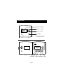
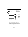
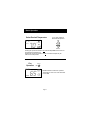
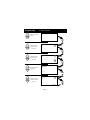
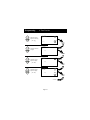
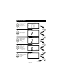
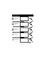
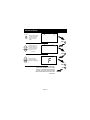
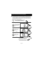
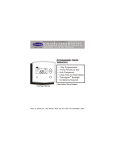
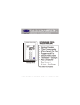
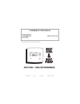
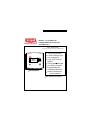
USERS INFORMATION MANUAL
Heating & Cooling Systems
MODEL TSTATBBPS701
PROGRAMMABLE DIGITAL
THERMOSTAT
NOTE TO INSTALLER:
This manual must be left with the equipment user.
6:03
Su
AUTO
68
Am
70
o
COOL
67
HEAT o
Heat Pump & Heat Cool
7 Day Programmable
4 Time Periods per Day
Auto Changeover
Large, Easy To Read
Display
Thermoglow Backlight
Very Easy to Program
Programmable Fan
No Batteries Required
Outdoor Temperature
Sensor Available
Meets California Title 24 Residential
Table Of Contents
FRONT PANEL
DISPLAY
QUICK START Set the clock and go
BASIC OPERATION
PROGRAMMING 4 Time Periods
ADVANCED SETUP
ABOUT ADVANCED OPERATION
WARRANTY
2
3
5
6
8
12
17
23
CAUTION
Follow Installation Instructions before proceeding.
SET THERMOSTAT TO MODE “OFF” PRIOR TO
CHANGING SETTINGS IN SETUP OR RESTORING
FACTORY DEFAULTS.
Residential Light Commercial Systems
Carrier Corporation 4/01
TSTATBBPS101
Page 1
Front Panel
Backlit LCD Display
6:03
Su
AUTO
68
Am
70
Warmer or + Button
o
COOL
67
HEAT o
Cooler or - Button
Mode Button
Heat or Cool Indicator
Red = Heat, Green = Cool
Programmable
Thermostat
6:03
S
AUTO
68
FAN
FAN OUTSIDE
Page 2
Am
OUTSIDE
70
o
COOL
67
HEAT o
VACATION PROGRAM SET CLOCK
MODE
VACATION PROGRAM SET CLOCK
Display
11
2
9
1
1
10
:
12:00
SMTWTFS
7
88
Am ProgramOn Setup
Start Locked
Pm
88
ServiceFilter
AUTO
OFFNight
6
Morning Day
Evening
8
Fan On
o
COOL
Outside
88
HEAT o
4
1
5
1
4
3
1
Mode Indicators
Selects the operation mode of the equipment.
HEAT - indicates the heat mode.
COOL - indicates the air conditioning mode.
AUTO - indicates the system will automatically
changeover between heat and cool modes
as the temperature varies.
OFF - indicates the entire system is turned off.
PROGRAM ON - indicates the stored program
is enabled to run. Page 8.
2
Clock with Day of the Week
Indicates the current time and day. This clock is
also used to program the timer periods. Page 5.
3
Room Temperature Display
Indicates the current room temperature.
4
Desired Set Temperature
Indicates desired room temperature(s). Page 7.
Page 3
Display
5
Outside Indication
Indicates the temperature displayed is from
the optional outside sensor. Page 21.
6
Morning, Day, Evening & Night Indication
Indicates the program time period. Page 8-11.
7
Setup Indication
Indicates the thermostat is in the programming
mode. Page 12.
8
Fan Operation Indication
Fan On - indicates constant, continuous fan
operation.
When Fan On is not lit - indicates the fan will
only operate when necessary to heat or
to cool. Page 7.
9
Service Filter Indication
Service Filter indicates when the filter should
be serviced under normal conditions.
Appears after 0 - 1950 hours of blower
operation (adjustable). Page 15.
10
Locked Indication
Locked appears after the right combination of
buttons are pressed, rendering the buttons
inoperative. Page 22.
11
Start Indication
Start appears when programming
timer functions. Page 8.
Page 4
Quick Start Set the Clock and Go
During Setup & Programming:
SET CLOCK
Press the SET CLOCK
button.
:
12:00
Am
Setup
i
Pressing the Up and Down
buttons will modify the flashing
selection.
.
(Represented in dark black)
Press
MODE
Setup
To adjust the
clock or Day use
2
S
buttons.
Press the SET CLOCK
button as above to
return to normal
operation.
SET CLOCK
This thermostat is preprogrammed from the
factory to operate 1 or 2 Stage equipment without
the need for further programming. To optimize the
installation of this thermostat follow the instructions
in the Advanced Setup section.
Page 5
Basic Operation
Select Mode
The HEAT setting indicates the
temperature the room has to
reach before the furnace will
turn on to heat the room.
The COOL setting indicates the
temperature the room has to
reach before the air conditioner
will turn on to cool the room.
AUTO will automatically select
heat or cool based on room
temperature demand.
Program On will activate the
stored timer operation.
(Morning, Day, Evening
& Night Periods)
OFF indicates both heating
and air conditioning
systems are turned off.
:
12:00
M
70
70
70
70
70
:
12:00
M
:
12:00
M
AUTO
:
12:00
M
Pm
Pm
Pm
ProgramOn
Pm
Day
:
12:00
M
OFF
Pm
Page 6
69
72
HEAT o
Press
MODE
o
COOL
Press
MODE
72
o
COOL
69
HEAT o
Press
MODE
73
o
COOL
70
HEAT o
Press
MODE
Basic Operation
Select Desired Temperature
:
12:00
M
AUTO
72
70
Pm
o
In any mode, adjust the
desired Set Temperature
with
COOL
69
HEAT o
buttons.
Pressing the Up or Down buttons in Auto mode will adjust both the heat and cool
set temperatures simultaneously.
Pressing the Up or Down buttons in Heat or Cool modes will adjust only the
heat or cool set temperature.
Fan
Operation
:
12:00
S
Fan On
Press
FAN
65
Pm
85
o
COOL
55
HEAT o
Fan On indicates constant fan operation.
This feature is active even if the thermostat
is set to Off.
Page 7
Programming
Press
PROGRAM
4 Time Periods
Press the PROGRAM button to enter time period programming.
Use the back cover Programming Worksheet to help with this section.
M
Select the day of week
(M - S)
Press
MODE
Adjust the start time
for Morning.
7M:30
Am
Start
Morning
Press
MODE
Adjust the cooling
setpoint for Morning.
(35 - 99 )
7M:30
Am
74
o
COOL
Morning
Press
MODE
Adjust the heating
setpoint for Morning.
(35 - 99 )
7M:30
Am
Morning
74
o
COOL
72
HEAT o
Continued
Page 8
Press
MODE
Programming
Adjust the start time
for Day.
4 Time Periods
I0M:30
Am
Start
Day
Press
MODE
Adjust the cooling
setpoint for Day.
I0M:30
(35 - 99 )
75
Am
o
COOL
Day
Press
MODE
Adjust the heating
setpoint for Day.
(35 - 99 )
Adjust the start time
for Evening.
I0M:30
75
Am
COOL
73
HEAT o
Day
5M:30
o
Pm
Press
MODE
Start
Evening
Press
MODE
Adjust the cooling
setpoint for Evening.
5M:30
Pm
75
o
COOL
(35 - 99 )
Press
Evening
MODE
Continued
Page 9
Programming
Adjust the heating
setpoint for Evening.
(35 - 99 )
4 Time Periods
5M:30
75
Pm
o
COOL
73
HEAT o
Evening
Press
MODE
Adjust the start time
for Night.
I MI :30
Pm
Start
Night
Press
MODE
Adjust the cooling
setpoint for Night.
I MI :30
Pm
78
o
COOL
Night
(35 - 99 )
Press
MODE
Adjust the heating
setpoint for Night
(35 - 99 )
I MI :30
Am
Night
78
o
COOL
70
HEAT o
Press
MODE
Continued
Page 10
Programming
4 Time Periods
The copy command becomes available after
programming the entire previous day.
Yes
Select Yes or No to copy
the previous day’s
program to this day.
No
:
18:no
T
co
py
If No is selected:
If Yes is selected:
Press
MODE
Selecting Yes, then pressing mode will copy the
previous day’s program and then will ask the
same copy question again. If yes is selected
each time, this routine will repeat.
If No is selected, as in previous steps, flashing prompts for input will appear for
the 4 time periods for the next day.
Page 11
Press
MODE
Advanced Setup
MODE
PROGRAM
Press the Mode button.
While holding the Mode,
press the Program button
to enter Setup screens.
Adjust the time of day
clock.
I2:00
AM
NOTE: Each step # is located at
the top right corner of the
display for easy reference.
Setup
I
Tip: To change hours quickly, press and
hold the override button in and press
the up or down buttons.
Press
Setup
Mo
2
MODE
Select the day of the
week.
Press
Setup
On
Select residential Heat
Pump, On or Off.
Off
OFF
HP
O
Setup
B
Select the reversing
valve polarity for
Heat Pump, O or B.
(Step 4 only appears if
heat pump is on in step 3)
O
3
MODE
4
MODE
Press
Press
MODE
Continued
Page 12
Advanced Setup
5
Setup
On
Select Electric Heat On
or Off. (Step 5 only
appears if heat pump is
off in step 3)
OFF
Off
88
Adjust the deadband
from 1 - 6 degrees.
8If
Adjust the minimum
difference between
cooling & heating
setpoints.
EH
6
2
7
2
8
6 Cy
Setup
Setup
Press
MODE
Press
MODE
COOL
HEAT
(0 - 6 )
Setup
Select the cycles per
hour limit.
d=cycles per hour
limit defeated.
d1=d + defeat 5 min.
Compressor lockout.
(d, d1, 2 - 6)
Press
MODE
Press
:
0:00
Adjust the programmable
fan timer.
0 - 60 minutes.
0:00 = off
Setup
9
MODE
Fan On
Press
MODE
Continued
Page 13
Advanced Setup
7:00
Am
On Setup
Adjust the programmable
fan start time. (step 10
appears only if step 9
is not 0:00)
I0
Press
Fan On
MODE
9:00
Adjust the programmable
fan stop time. (step 11
appears only if step 9
is not 0:00)
Setup
Pm
II
OFF
Press
Fan On
MODE
On Setup
LI
On
Select the display backlight always On, or Off
after 8 seconds.
Off
I2
Press
MODE
0
Press
Setup
I3
Reset the Energy Watch
Heat hour counter.
HEAT
FAN
(0 - 1999)
Press
MODE
0
Press
Setup
I4
COOL
Reset the Energy Watch
Cool hour counter.
FAN
Press
(0 - 1999)
MODE
Continued
Page 14
Advanced Setup
I5
0
Press
Reset the Service Filter
counter. This will also
remove the Service
Filter icon from the
display
FAN
Setup
ServiceFilter
Press
MODE
Adjust the number of
hours the blower will
run before the Service
Filter icon appears on
the display. 0 = off.
0
Setup
I6
ServiceFilter
(0 - 1950)
Press
MODE
F
C
Select thermostat
operation in degrees
Fahrenheit or Centigrade.
F
Setup
I7
Press
MODE
Press the Mode button.
While holding the Mode, press the Fan
button for 2 seconds to leave the Setup
screens. If no buttons are pressed, the
display will leave the setup screens after
30 seconds.
Page 15
FAN
Advanced Setup
Advanced Setup Table
Step #
1
2
3
4
5
6
7
8
9
10
11
12
13
14
15
16
17
Description
Range
Time of day clock set
Day of the week
Heat Pump
Reversing Valve polarity
Electric Heat
Deadband or Temperature swing
Forced minimum difference heat/cool
Cycles per hour
Programmable Fan
Programmable Fan Start Time
Programmable Fan Stop Time
Thermoglow backlight
Energy Watch - Heat Timer
Energy Watch - Cool Timer
Reset Service Filter icon
Service Filter run time set
Fahrenheit or Centigrade
Page 16
24 hour
Sun - Sat
Off / On
O/B
Off / On
1-6
0-6
d, d1, 2 - 6
0:00 - 0:60
24 hour
24 hour
Off / On
0 - 1999
0 - 1999
-0 - 1950
F/C
Factory Default
12:00 Am
Monday
Off
O
Off
1
2
6
0:00
7:00 Am
9:00 Pm
On
0
0
-0
F
About Advanced Features & Operation
MEMORY BACKUP - In the event of a power loss, the
thermostat will retain the stored program settings without
external power or batteries.
2 STAGE OPERATION - The 2nd Stage of heat or cool is
turned on when (1) the 1st Stage has been on for a
minimum of two minutes, and (2) the temperature spread
from the setpoint is equal to or greater than: the setpoint
plus the deadband, plus 2 degrees.
Cooling
Heating
2 degrees
2nd Stage
turn on
1st Stage
turn on
Dead
Band
Heat
Setpoint
Dead
Band
Cool
Setpoint
2 degrees
1st Stage
turn on
2nd Stage
turn on
MINIMUM HEAT/COOL SETPOINT DIFFERENCE - The Heat
and Cool setpoints will not be allowed to come any closer
to each other than the value set in Advanced Setup step
# 7, on page 13. This minimum difference is enforced
during Auto changeover and Program On operation.
PROGRAMMABLE FAN - If the Programmable Fan timer is
set to a value other than 0:00, the fan will run for the
preprogrammed amount of time, page 13, step# 9.
The Programmable Fan timer will start the fan at the top
of each hour. The Programmable Fan may be active
even if the thermostat mode is Off. Steps 10 & 11
restrict the hours in which Programmable Fan may
operate. Step# 10, page 14 is the start time and step# 11
is the stop time. Setting the times to the same setting
in both steps 10 & 11 will allow Programmable Fan to
operate 24 hours a day.
Page 17
About Advanced Features & Operation
EMERGENCY HEAT - Is a feature available to Heat Pump
installations. To turn on Emergency Heat press in the
Fan button. While holding the Fan button press the
Up button for 2 seconds. The Cool setpoint display
will read ‘EH’.
:
12:00
Press for
Emergency Heat
73
Am
eh
o
74
HEAT o
FAN
During Emergency Heat the thermostat will turn
on the fan and the 2nd stage of heat, when there is a
demand for heat, locking out the 1st stage compressor.
Exiting Emergency Heat is the same as entering. During
Emergency Heat only OFF and HEAT are available.
ELECTRIC HEAT - Selecting Electric Heat on, page 13,
step 5, will cause the thermostat to turn on the fan
immediately any time there is a heat demand. Since all
gas furnaces control the fan, this feature should be off
unless the heater is only electric.
Page 18
About Advanced Features & Operation
KEYPAD LOCK - To prevent unauthorized use of the thermostat,
the front panel buttons may be disabled. To disable, or
‘lock’ the keypad, press and hold in the Mode button.
While holding the Mode button in, press the Up and Down
buttons in together. The Locked icon will appear on the
display.
:
12:00
65
Press all 3 for
Keypad Lockout
MODE
Pm
Locked
85
COOL
55
HEAT o
To unlock the buttons, again press and hold the Mode
button. While holding the Mode button in, press the Up
and Down buttons in together. The Locked icon will
disappear from the display.
Page 19
o
About Advanced Features & Operation
VACATION MODE - When the thermostat is in Vacation mode, the
thermostat will operate under the Vacation time period set points.
In order for Vacation mode to become active the thermostat must
be in the Program On mode. Vacation mode will take effect when
the time clock reaches 12:00am.
VACATION
Press the VACATION button to enter the
vacation programming setup steps.
0
85
55
23
Setup
Select the number of days
that the Vacation Schedule
will be in effect. A value
of 0 disables Vacation
mode.
unoccupied
8y
24
Press
MODE
Setup
unoccupied
Adjust the cooling
setpoint for Vacation
mode.
(35 - 99 )
COOL
Press
25
Setup
unoccupied
Adjust the heating
setpoint for Vacation
mode.
(35 - 99 )
MODE
HEAT
Press
VACATION
Press the Vacation button to exit
the Setup screens. If no buttons are
pressed, the display will leave the
setup screens after 30 seconds.
Page 20
About Advanced Features & Operation
DUAL SETPOINT BEHAVIOR - The adjustable setpoint range
is: 35 - 99 degrees in Fahrenheit and 7 - 35 degrees in
Centigrade. When in the modes Heat or Cool, this
adjustable range is unhampered.
When adjusting any Auto mode, including programming
4 Time periods, the thermostat will not allow the
Heat setpoint to get closer to the Cool setpoint
than the value programmed as the minimum difference
in step 7, page 13.
When entering the Auto mode from Cool, the Heat and
Cool setpoints will remain spread apart by the amount
that they were adjusted, prior to entering Auto.
For example: If the Cool setpoint was set to 80 while
in the Cool mode and the Heat setpoint was adjusted to
70 while in the Heat mode, upon entering the Auto mode
the Heat and Cool setpoints would be 80 and 70. Both
setpoints would then move up and down together, (in this
example spread by 10 degrees), by pressing the up or
down buttons.
To move the Heat and Cool setpoints closer together,
enter the Cool or Heat mode by pressing the Mode button,
then adjust the setpoint(s) closer together. Heat is limited
to how close it can come to Cool by step 7, page 13.
Page 21
About Advanced Features & Operation
OUTSIDE SENSOR (Optional Accessory) - When connected
to terminals RS+5, RS, & GND on the back of the
thermostat, the thermostat will read the temperature from
the Outside Sensor when asked to. This thermostat will
not control to this sensor, it is only to read outside
temperature.
To read the temperature from the Outside Sensor,
press the Outside button of the thermostat .
The display will then only show Outside temperature.
Pressing the Outside button will then return the display to
normal operation.
The Outside Sensor is available in a wired or wireless
version. The wired sensor can be connected to the
thermostat with up to 500’ of 20 ga. or 300’ of 18 ga.
Unshielded, thermostat wire.
See the Outside Sensor instructions for further details.
FACTORY DEFAULTS - If, for any reason it is desirable to
return all stored settings back to the factory default
settings, press the Mode button. While holding the Mode
button in, press the Fan button for 5 sec. All icons will
appear. Press and hold in the Fan button until Fd
appears. This resets all factory settings. To calibrate
room temperature, press the Up and Down arrow buttons
simultaneously, twice.
At this point use the Up and Down buttons to calibrate
room temperature, if needed. Press the Mode button to
return to normal operation. NOTE CAUTION ON PAGE 1.
Page 22
Warranty
Five-Year Warranty - This Product is warranted to be free from defects in material and
workmanship. If defect appears within five years from the date of original installation, whether
or not actual use begins on that date, then the product does meet this warranty. A new or
remanufactured part, at the manufacturer’s sole option, to replace any defective part will be
provided without charge for the part itself; PROVIDED the defective part is returned to the
distributor through a qualified servicing dealer.
THIS WARRANTY DOES NOT INCLUDE LABOR OR OTHER COSTS incurred for diagnosing,
repairing, removing, installing, shipping, servicing or handling of either defective parts or
replacement parts. Such costs may be covered by a separate warranty provided by the installer.
THIS WARRANTY APPLIES ONLY TO PRODUCTS IN THEIR ORIGINAL INSTALLATION
LOCATION AND BECOMES VOID UPON REINSTALLATION.
LIMITATIONS OF WARRANTIES – ALL IMPLIED WARRANTIES (INCLUDING IMPLIED
WARRANTIES OF FITNESS FOR A PARTICULAR PURPOSE AND MERCHANTABILITY) ARE
HEREBY LIMITED IN DURATION TO THE PERIOD FOR WHICH THE LIMITED WARRANTY
IS GIVEN. SOME STATES DO NOT ALLOW LIMITATIONS ON HOW LONG AN IMPLIED
WARRANTY LASTS, SO THE ABOVE MAY NOT APPLY TO YOU. THE EXPRESSED
WARRANTIES MADE IN THIS WARRANTY ARE EXCLUSIVE AND MANY NOT BE ALTERED,
ENLARGED, OR CHANGED BY ANY DISTRIBUTOR, DEALER, OR OTHER PERSON
WHATSOEVER.
ALL WORK UNDER THE TERMS OF THIS WARRANTY SHALL BE PERFORMED DURING
NORMAL WORKING HOURS. ALL REPLACEMENT PARTS, WHETHER NEW OR
REMANUFACTURED, ASSUME AS THEIR WARRANTY PERIOD ONLY THE REMAINING
TIME PERIOD OF THIS WARRANTY.
THE MANUFACTURER WILL NOT BE RESPONSIBLE FOR:
1. Normal maintenance as outlined in the installation and servicing instructions or owners
manual including filter cleaning and/or replacement and lubrication.
2. Damage or repairs required as a consequence of faulty installation, misapplication, abuse,
improper servicing, unauthorized alteration or improper operation.
3. Failure to start due to voltage conditions, blown fuses, open circuit breakers or other
damages due to the inadequacy or interruption of electrical service.
4. Damage as a result of floods, winds, fires, lightning, accidents, corrosive environments or
other conditions beyond the control of the Manufacturer.
5. Parts not supplied or designated by the Manufacturer, or damages resulting from their use.
6. Manufacturer products installed outside the continental U.S.A., Alaska, Hawaii, and
Canada.
7. Electricity or fuel costs or increases in electricity or fuel costs from any reason whatsoever
including additional or unusual use of supplemental electric heat.
8. ANY SPECIAL INDIRECT OR CONSEQUENTIAL PROPERTY OR COMMERCIAL
DAMAGE OF ANY NATURE WHATSOEVER. Some states do not allow the exclusion of
incidental or consequential damages, so the above may not apply to you.
This warranty gives you specific legal rights, and you may also have other rights which may vary
form state to state.
Page 23
Programming Worksheet
see page 8
DAY PERIOD START TIME COOL HEAT
Morning
M
O
N
D
A
Y
T
U
E
S
D
A
Y
W
E
D
N
E
S
D
A
Y
T
H
U
R
S
D
A
Y
F
R
I
D
A
Y
S
A
T
U
R
D
A
Y
S
U
N
D
A
Y
Day
Evening
Night
Morning
Copy Mon
Tue
Day
No
Evening
Yes
Night
Morning
Copy Tue
Wed
Day
No
Evening
Yes
Night
Morning
Copy Wed
Thu
Day
No
Evening
Yes
Night
Morning
Copy Thu
Fri
Day
No
Evening
Yes
Night
Morning
Copy Fri
Sat
Day
No
Evening
Yes
Night
Morning
Copy Sat
Sun
Day
No
Evening
Yes
Night
Printed on recycled paper.
P/N 88-307
Rev. 1
Form No. OM17-45
Catalog No. 13TS-TA52