1
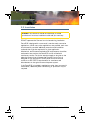
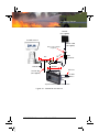
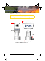
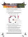
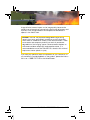
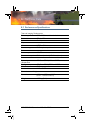
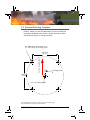
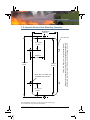
PatrolIR B Pan and Tilt User’s Guide Document # 427-0026-01-10 Version 110, Oct 2010 © FLIR Systems, Inc., 2010. All rights reserved worldwide. No parts of this manual, in whole or in part, may be copied, photocopied, translated, or transmitted to any electronic medium or machine readable form without the prior written permission of FLIR Systems, Inc. Names and marks appearing on the products herein are either registered trademarks or trademarks of FLIR Systems, Inc. and/or its subsidiaries. All other trademarks, trade names, or company names referenced herein are used for identification only and are the property of their respective owners. This product is protected by patents, design patents, patents pending, or design patents pending. This document is controlled to FLIR Technology Level 1. The information contained in this document pertains to a dual use product controlled for export by the Export Administration Regulations (EAR). FLIR trade secrets contained herein are subject to disclosure restrictions as a matter of law. Diversion contrary to U.S. law is prohibited. U.S. Department of Commerce authorization is not required prior to export or transfer to foreign persons or parties unless otherwise prohibited. PatrolIR B 70 Castilian Drive Goleta, CA 93117 Phone: +1.888.747.FLIR (+1.888.747.3547) www.flir.com Revision History Revision Date Comment 100 July 2009 First release 110 Oct 2010 Added JCU information & other minor changes PatrolIR B Pan and Tilt User’s Guide Table of Contents 1 Warnings and Cautions 2 Introduction 3 Getting Started 3.1 Parts List .................................................................... 5 3.2 Operational Overview ..................................................... 5 3.3 Installation ................................................................... 6 3.3.1 Camera Mounting ................................................ 8 3.3.2 Fuse and Joystick Control Unit Mounting ............... 11 3.4 Using your PatrolIR B .................................................. 13 3.4.1 Joystick Control Unit (JCU) .................................. 13 4 Caring for your PatrolIR B 4.1 Troubleshooting ......................................................... 17 4.2 Replacing the fuses .................................................... 17 4.2.1 Cleaning ........................................................... 18 5 Optional Accessories 5.1 Optional JCUs and Extension Cables ............................. 19 6 Technical Data 6.1 Performance Specifications .......................................... 21 7 Mounting Templates 7.1 Camera Mounting Template. ........................................ 23 7.2 Joystick Control Unit Mounting Template. ....................... 25 427-0026-01-10, version 110 Oct 2010 iii iv Oct 2010 427-0026-01-10, version 110 1 Warnings and Cautions This guide uses the term Caution to indicate a potentially hazardous situation, which, if not avoided, may result in injury, damage to the vehicle or PatrolIR B, or other property damage. Caution! Failure to follow the caution may result in damage to the equipment or injury. Warnings and Cautions: Do not operate any function that takes your attention away from safely driving your vehicle. Any function that requires your prolonged attention should only be performed after coming to a complete stop. Always stop the vehicle in a safe location before performing these functions. Failure to do so may result in an accident. Use this product for mobile 12VDC applications. PatrolIR B is designed for commercial, over-the-road, automotive applications. While many other applications are possible, each user should carefully consider additional protection and installation methods that might be required for a given application. Mechanical, environmental and electrical requirements should be evaluated to assure that the PatrolIR B can be utilized with satisfactory results. Particular attention needs to be given to the electrical system that will power the PatrolIR B as the unit is designed for the automotive 12VDC power environment and conforms to ISO 7637-2 requirements for transients and disturbances on the typical automotive power system. If the PatrolIR B is installed in applications other than commercial automobiles, additional power conditioning or protection may be required. Consult your local and state driving regulations prior to installation. In many states using active monitors in view of the driver is prohibited. Consult your local and state driving regulations for laws and guidelines. User assumes all risks and indemnifies the manufacturer from any liability. 427-0026-01-10, version 110 Oct 2010 1 1 – Warnings and Cautions Minimize display viewing while driving. Viewing the display may distract the driver from looking ahead and may result in an accident. The PatrolIR B thermal imaging system should not be used as a substitution for head lamps or head lamp assisted human vision during vehicle operation. When installing the PatrolIR B, do not block the vehicle’s vents or radiator panels. Doing so may result in heat buildup, equipment breakage, and/or fire. Caution! The PatrolIR B thermal imaging system is not intended to be used as the primary navigation system. The PatrolIR B should not to be used as a substitution for head lamps or head lamp assisted human vision during vehicle operation. It should be used only as an aid to cautious night-time driving. Note: All thermal imaging systems are subject to export control. Please contact FLIR for export compliance information concerning your application or geographic area. 2 Oct 2010 427-0026-01-10, version 110 2 Introduction Congratulations! The FLIR PatrolIR B is a state-of-the-art thermal imaging system that will provide you with excellent night visibility and situational awareness, without any form of natural or artificial illumination. The PatrolIR B system is designed for simple, intuitive operation. The basic system includes a camera assembly and a joystick control panel. The PatrolIR B uses standard 12 VDC battery power and the images from the 320 x 240 pixel detector are compatible with virtually any existing display and recorder that accepts composite video. The PatrolIR B is available with NTSC output, the same format used on common television and VCR video input in the Americas and some Asian countries. It is also available with PAL output, the same format used on common televisions and VCR video input in Europe. The PatrolIR B features a wide field of view and is capable of providing an image even in absolute darkness. 427-0026-01-10, version 110 Oct 2010 3 2 – Introduction Figure 2-1: PatrolIR B Makes the Difference The upper image represents what the human eye sees looking at a camouflaged subject in shady brush. The lower image is an infrared thermal picture taken at the same moment as the visible image above. 4 Oct 2010 427-0026-01-10, version 110 3 Getting Started 3.1 Parts List The PatrolIR B camera and its accessories are delivered in a box which contains the items below. • PatrolIR B camera with attached 30" integrated cables with connectors • Joystick Control Unit cable, 22' long • Video cable with BNC video connector 22' long • Pre-Wired Joystick Control Unit (JCU) with integrated power cable (fuse holder, power leads) Two JCU models available; they are functionally the same but one is intended to be mounted horizontally and the other is mounted vertically. Camera FLIR PN White color, NTSC, Horiz JCU 427-0026-01-00 White color, NTSC Export, Horiz JCU 427-0026-01-00S White color, PAL, Horiz JCU 427-0026-02-00 White color, PAL Export, Horiz JCU 427-0026-02-00S White color, NTSC, Vert JCU 427-0026-03-00 White color, NTSC Export, Vert JCU 427-0026-03-00S White color, PAL, Vert JCU 427-0026-04-00 White color, PAL Export, Vert JCU 427-0026-04-00S Mounting hardware for the camera, mounting hardware for the Joystick Control Unit, 5-amp fuses, cable clips, and extra electrical components PatrolIR B Pan and Tilt User’s Guide 427-0026-01-10 3.2 Operational Overview The PatrolIR B is easy to install and operate. The system operates on 12 volts DC and there are no camera adjustments. The thermal imaging camera inside the PatrolIR B is completely sealed and extremely rugged. The camera has been qualified for operation in all types of weather conditions over the specified operating temperature range and includes an automatic window heater that will prevent icing under most conditions. 427-0026-01-10, version 110 Oct 2010 5 3 – Getting Started 3.3 Installation Caution! The PatrolIR B should be installed by a trained professional. Incorrect installation could void your warranty. DO NOT separate the Camera from its base during installation. PatrolIR B is designed for commercial, over-the-road, automotive applications. While many other applications are possible, each user should carefully consider additional protection and installation methods that might be required for a given application. Mechanical, environmental and electrical requirements should be evaluated to assure that the PatrolIR B can be utilized with satisfactory results. Particular attention needs to be given to the electrical system that will power the PatrolIR B as the unit is designed for the automotive 12VDC power environment and conforms to ISO 7637-2 requirements for transients and disturbances on the typical automotive power system. If the PatrolIR B is installed in applications other than commercial automobiles, additional power conditioning or protection may be required. 6 Oct 2010 427-0026-01-10, version 110 3 – Getting Started Monitor (not supplied) PatrolIR Camera Monitor cable (not supplied) BNC to RCA adapter (supplied) 22 30 “ Ground wire t fee BNC connector 22 feet 5A Fuse Junction box (not supplied) 12 VDC Return Joystick Control Unit Ground wire Figure 3-1: PatrolIR B Pan and Tilt 427-0026-01-10, version 110 Oct 2010 7 3 – Getting Started 3.3.1 Camera Mounting Caution! The PatrolIR B is intended to be mounted above the mounting plane. Any other type of installation is not appropriate. 187 mm (7.33 inches) 242 mm (9.50 inches) Cable seal Primary Viewing Direction Figure 3-2: PatrolIR B Pan and Tilt 8 Oct 2010 427-0026-01-10, version 110 3 – Getting Started Mount the camera with the front of the base towards the primary viewing direction. The camera will rotate (pan) approximately 180 in either direction from the primary viewing direction. Your PatrolIR B can be installed with machine screws, washers, and lock washers as described below. 5.1mm (0.20”) for machine screw 62.7mm (2.47”) 62.7mm (2.47”) Primary Viewing Direction Step 1 Drill the screw mounting holes per the installation template provided in paragraph 7.1 “Camera Mounting Template.” on page 23. A sketch is shown below in Figure 3-3. clocking-pin hole 1/4” x 20 mounting hole This drawing is not to scale Figure 3-3: Base Mounting Template for the Camera Step 2 Check that all the screw holes line up and the front of the camera base is towards the primary viewing direction. (The cables exit the rear of the camera base.) Step 3 Using a 3mm Allen wrench, securely fasten the camera in place with four M5 socket-head machine screws, flat washers, and lock washers provided. See Figure 3-4 Step 4 While the quick-connect connections are sealed, it is recommended that the installer route the control/power and video cables from the camera to a water-proof junction box within 30 inches of the camera head. This is the location for the quick-connect connections to the internal vehicle cables. 427-0026-01-10, version 110 Oct 2010 9 3 – Getting Started Step 5 Route the 22’ JCU cable from the cable splice connector to the Joystick Control Unit mounting location and the 22’ video cable from the video cable splice connector to the monitor. See Figure 3-1 for a schematic representation of the cabling connections. Step 6 Securely attach the green ground wire to the vehicle ground plane. mounting surface flat washer (4) lock washer (4) screw (4) Figure 3-4: Securing the Camera 10 Oct 2010 427-0026-01-10, version 110 3 – Getting Started 3.3.2 Fuse and Joystick Control Unit Mounting Caution! Changing the wiring configuration of the PatrolIR B or attempting to utilize controllers or wiring harnesses other than those supplied by FLIR may cause permanent damage to the unit and may void the warranty. Caution! Do not connect the camera to anything other than 12 VDC power. Operating the camera outside of the specified input voltage range or the specified operating temperature range can cause permanent damage. Note: While the illustrations in this User’s Guide show the Horizontal JCU configuration, PatrolIR B is available with a Vertical JCU that is electrically and functionally identical, but it has a label that allows the JCU to be mounted in a vertical orientation. Please refer to section Chapter 3.1 “Parts List” on page 5 and section Chapter 5.1 “Optional JCUs and Extension Cables” on page 19 for more information. After routing the cables to the desired location for the monitor and the Joystick Control Unit, verify that the cables will reach before cutting and drilling any mounting holes. 427-0026-01-10, version 110 Oct 2010 11 3 – Getting Started 139.7mm (5.50”) 31.75mm (1.25”) DRILL 6.4mm (0.25”) for threaded stud six places 34.3mm (1.35”) 31.75mm (1.25”) 60.325mm (2.375”) 132mm (5.20”) CUT for JCU This drawing is not to scale Figure 3-5: Joystick Control Unit mounting template Step 1 Drill holes for the six studs and cut an access hole for mounting the Joystick Control Unit per the installation template provided in paragraph 7.2 “Joystick Control Unit Mounting Template.” on page 25. A sketch is shown in Figure 3-5. Step 2 Connect the JCU cable from the camera to the Primary connector on the back of the JCU. See Figure 3-6. Power/control to optional secondary JCU Power from fuse panel Power/control to camera ground wire Figure 3-6: Joystick Control Unit Power and Control 12 Oct 2010 427-0026-01-10, version 110 3 – Getting Started Step 3 Check the gasket under the Joystick Control Unit for integrity and securely fasten the switch in place with the two M4 flat washers, lock washers, and hex nuts provided. Step 4 Securely attach the green ground wire to the vehicle ground plane. Step 5 Connect the 12 VDC power and return wires from the JCU wiring harness to your fuse panel. Wire gauge must be in accordance with the applicable electrical standards. Note: Depending on your JCU mounting location you may want to connect the ground wire and power cables either before or after installing the JCU. 3.4 Using your PatrolIR B Caution! The PatrolIR B imaging system is not intended to be used as the primary navigation system. It should be used in conjunction with other navigation aids and a primary manual navigation system. The PatrolIR B is easy to use, but you should take a moment to carefully read this section so you fully understand how to use the controls and what you are seeing on your display. While the imagery you will see on the monitor may look like black and white daylight video, it isn’t! A few tips on how to interpret some of the imagery will help you to make the most of your system. 3.4.1 Joystick Control Unit (JCU) The PatrolIR B camera system is controlled with the JCU touch pad and joystick. PatrolIR B is available with either a horizontal or vertical JCU. While the illustrations in this User’s Guide show the Horizontal JCU configuration, a Vertical JCU is also available that is electrically and functionally identical, but it has a label that allows the JCU to be 427-0026-01-10, version 110 Oct 2010 13 3 – Getting Started mounted in a vertical orientation. Both JCU models have the same size and mounting features/hardware. Power—Your PatrolIR B offers a unique instant power on. Upon receiving power from the vehicle it automatically powers on and displays video to the monitor (client supplied). Additionally, you can manually turn the PatrolIR B on and off by pressing the power button. DIM—controls the brightness of the JCU panel; enabled anytime power is on. HOME—moves the camera to the last home position setting. Or, when held down for at least four seconds, sets the current position as the home position. ZOOM—selects either 1x or 2x as the zoom setting. SCENE—cycles through gain settings to change the brightness and contrast of the image. Varying environmental conditions may make one setting more appropriate than another for any operation. B/W—selects black hot, white hot, or red hot video image mode. Hot object appear black, white, or red respectively depending on the selected mode. The choice of video image mode is strictly a personal preference and you should experiment to find your preferred mode. Joystick—move to the left or right to rotate the camera; up or down to raise or lower the camera. Make sure that the camera power is switched on at your main power panel. Ensure that your display is turned on and you have selected the PatrolIR B as the source for your display. 14 Oct 2010 427-0026-01-10, version 110 3 – Getting Started The camera automatically adjusts to changing scene conditions. However, the camera does contain four preset conditions that might provide better imagery in certain conditions. The thermal imager inside the camera does not sense light like conventional cameras; it senses heat or temperature differences. As you experiment with the system during daylight and nighttime operation, you will notice differences in the picture quality; this is normal. The camera senses small “differences” in apparent radiation from the objects in view, and, in white hot mode, displays them as either white (or lighter shades of gray) for warmer objects, and black (or darker shades of gray) for colder objects. This is why you will see areas such as exhaust stacks or engines that appear white (or black, or red depending on the video image mode selected), while the rest of a vehicle may appear dark (or cool). Scenes with familiar objects will be easy to interpret with some experience. The camera automatically optimizes the image to provide you with the best contrast in most conditions. Thermal (radiant) energy emitted by objects that were warmed by the sun during the day can be reflected, in much the same way sunlight can be reflected. Do not assume that the objects you are looking for will be hot and therefore show up as white. Look for variations or anomalies in scenes that you think would normally be the same temperature. As you experiment with your PatrolIR B, you will see your world in a different light. Consider every object you view in terms of how it will look “thermally” as opposed to how it looks in the visible spectrum. For example, after sunset, objects warmed by the sun will radiate for several hours and will appear warmest right after sunset. Early in the morning, many of these objects will appear cooler than their surroundings, so be sure to look for subtle differences in the scene, as opposed to just hot (white) targets. Environmental conditions, including time of day, humidity, and precipitation, will affect the image quality. For example, the radiation of an object will be affected by even a thin layer of dew. The diurnal cycle that causes objects to heat up in the sun (this is known as solar loading) and cool off at night will also have an impact on the image. The range of temperatures of objects that appear in the 427-0026-01-10, version 110 Oct 2010 15 3 – Getting Started image will also have an impact on the image quality, because the camera has software that automatically controls the brightness and contrast of the image based on the temperature differences of objects in the field of view. Caution! The user may experience degraded images during certain short term atmospheric conditions such as those that allow water to condense or collect on the camera window. These occurrences are temporary and will not result in permanent degradation of the imaging system. Because water droplets on the camera window temporarily reduce performance, it is recommended to mount the PatrolIR B in a location with minimal exposure to water splash or spray. If you have any questions about the operation of your PatrolIR B, or you would like to provide feedback on the product, please feel free to call us at +1 888.747.FLIR in the United States. 16 Oct 2010 427-0026-01-10, version 110 4 Caring for your PatrolIR B 4.1 Troubleshooting Caution! Do not open the camera body for any reason. Disassembly of the camera (including removal of the cover) can cause permanent damage and will void the warranty. If the camera will not produce an image, check the inline fuse and the fuse panel. If a fuse has blown, determine the cause of the blown fuse, fix the problem, and replace with a 5 Ampere fuse. Check the wiring at both the fuse panel and at the termination to the JCU. Ensure that the contacts are clean dry and free from corrosion. If maintenance on the wiring connection is required, have an authorized service representative make the appropriate repairs. If the camera still will not produce an image, check the video connection at the camera and at your display. If the connectors appear to be properly engaged but the camera still does not produce an image, have an authorized service representative make the appropriate repairs. 4.2 Replacing the fuses Caution! Replace system fuses with the same value and type provided at the time of purchase. Using fuse values other than the ones supplied by FLIR Systems, Inc. may cause permanent damage to the unit and may void the warranty. To replace the fuse, ensure power is off, unscrew the fuse holder, remove the fuse and replace using a 5 Ampere automotive fuse. 427-0026-01-10, version 110 Oct 2010 17 4 – Caring for your PatrolIR B 4.2.1 Cleaning Caution! The camera window has an anti-reflective coating and should be cleaned only with low pressure fresh water and a lens cloth. Caution! Improper care of the camera window can cause damage to the anti-reflective coating, degrade the camera’s performance, and void the camera warranty. The camera housing has a durable coating. Rinse the camera housing with very low pressure fresh water to keep it clean. If the front window of the camera gets water spots, wipe it with a clean lens cloth folded in fourths dampened with water. Front Window Figure 4-1: PatrolIR B Front Window 18 Oct 2010 427-0026-01-10, version 110 5 Optional Accessories 5.1 Optional JCUs and Extension Cables FLIR Systems makes available replacement JCUs and Dual Station JCUs with extension cables. The part numbers are as follows: Description FLIR PN PatrolIR B JCU, Horizontal 4115072 PatrolIR B JCU, Vertical 4108783 PatrolIR B Dual Station Kit (includes Horizontal JCU and 50’ cable) 432-0001-14-04 PatrolIR B Dual Station Kit (includes Vertical JCU and 50’ cable) 432-0001-14-03 427-0026-01-10, version 110 Oct 2010 19 6 Technical Data 6.1 Performance Specifications Thermal Imaging Performance Sensor type 320 x 240 uncooled microbolometer Field of view 36 h x 27 v Spectral band 8 - 14 Outputs Video NTSC or PAL Connector types BNC at primary cable end Power Power requirements 12 VDC Power consumption 5 Watts (nominal), 45 Watts (max) Environmental Operating temperature -20C to +55C (-4F to +130F Storage temperature -50C to +80C (-58F to +266F Moisture IPX6 Sand and dust Mil-Std-810E Dimensions and Weight Dimensions 102mm x 187mm x 242mm (4w x 7.35d x 9.50h) Weight 4.08 kg (9 lb.) 427-0026-01-10, version 110 Oct 2010 21 7 Mounting Templates 7.1 Camera Mounting Template. Caution: When you print this document from the .pdf file,the installation templates may not be to scale. Be sure to check the dimensions prior to cutting any holes. 4X on 88.9 mm (3.50") bolt circle 5.1 mm (0.20") for machine screw Camera View Direction 62.7mm (2.47”) clocking-pin hole 62.7mm (2.47”) 1/4” x 20 mounting hole For installation purposes, a tear out version of this page is located at the very back of this manual. 427-0026-01-10, version 110 Oct 2010 23 7 – Mounting Templates 7.2 Joystick Control Unit Mounting Template. 60.325mm (2.375”) CUT for JCU 34.3mm (1.35”) 139.7mm 5.50” 132mm (5.20”) DRILL 6.4 mm (0.25”) for threaded stud six places Caution: When you print this document from the .pdf file,the installation templates may not be to scale. Be sure to check the dimensions prior to cutting any holes. 31.75mm (1.25”) 31.75 mm (1.25”) For installation purposes, a tear out version of this page is located at the very back of this manual. 427-0026-01-10, version 110 Oct 2010 25 Caution: When you print this document from the .pdf file,the installation templates may not be to scale. Be sure to check the dimensions prior to cutting any holes. 4X on 88.9 mm (3.50") bolt circle 5.1 mm (0.20") for machine screw Camera View Direction Tear out here 62.7mm (2.47”) clocking-pin hole 62.7mm (2.47”) 1/4” x 20 mounting hole Full size PatrolIR B Mounting Template Caution: When you print this document from the .pdf file,the installation templates may not be to scale. Be sure to check the dimensions prior to cutting any holes. 60.325mm (2.375”) CUT for JCU 31.75mm (1.25”) Tear out here 34.3mm (1.35”) 34.3mm (1.35”) 132mm (5.20”) DRILL 6.4 mm (0.25”) for threaded stud six places 31.75 mm (1.25”) Full size Joystick Control Unit Mounting Template Santa Barbara Portland FLIR Commercial Systems 70 Castilian Dr. Goleta, CA 93117 USA PH: +1.888.747.FLIR (+1.888.747.3547) FLIR Corporate Headquarters FLIR Systems, Inc. 27700A SW Parkway Ave. Wilsonville, OR 97070 USA Netherlands Boston CS Eurasian Headquarters FLIR Commercial Systems B.V. Charles Petitweg 21 4847 NW Teteringen - Breda The Netherlands FLIR System Boston, Inc. 25 Esquire Road North Billerica, MA 01862