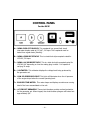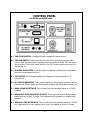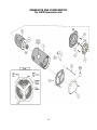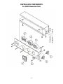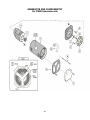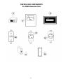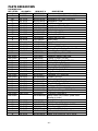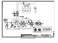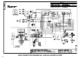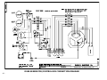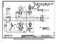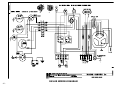
1
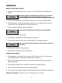
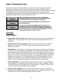
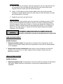
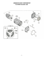
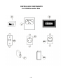
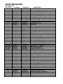
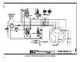
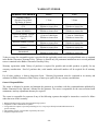
OPERATOR'S MANUAL
FOR YOUR
DG SERIES
GENERATOR
MODEL
__________
SERIAL #
__________
BALDOR GENERATORS
3815 Oregon Street, Oshkosh WI 54902
Phone 1-800-USA-POWR • Fax 920-236-4219
FORM#: S-PSG-002-11
DIESEL (DG) COVER\MSW'00
EFFECTIVE DATE: 4/4/97
REVISION DATE: 3/14/03
FORWARD
This manual contains the information you need to safely and efficiently operate your generator set.
During the preparation of this manual every effort was made to ensure the accuracy of its contents.
DO NOT OPERATE THIS GENERATOR SET UNTIL YOU CAREFULLY READ THIS MANUAL
AND UNDERSTAND THE SAFETY WARNINGS AND INSTRUCTIONS CONTAINED IN IT. While
safety is built into every Baldor Pow'R Gard generator set, careless or improper operation could
possibly result in mechanical failure, property damage, severe injury or even death.
Note that this manual covers only very basic information in regards to the engine. A separate
owner's manual for the engine is supplied with this unit for your use. Please refer to this manual for
information relative to engine operation, maintenance, recommendations and additional safety
warnings.
As soon as you receive your generator set, inspect it closely for shipping damage. If you find some
damage, notify the transportation company immediately and file a freight damage claim.
Think of this manual as a tool to help you get the most out of your generator set. WE STRONGLY
SUGGEST THAT YOU KEEP THIS MANUAL WITH YOUR GENERATOR SET AND MAKE IT
AVAILABLE TO ANYONE USING THE GENERATOR SET. You should refer to the manual when
questions arise in regards to the operation of the generator set and carefully observe all safety
warnings and instructions contained in it.
Baldor Generators, formerly Pow'R Gard Generator Corporation has been in business since 1965.
The generator sets we manufacture have earned the reputation of being of high quality and a
dependable product. We take pride in this fact and continue to keep our quality standards high on
our list of priorities. We are also constantly researching new technological ideas to determine if they
could be used to make our generator sets even better.
Thank you for purchasing your Baldor Pow'R Gard Generator Set.
-i-
SAFETY WARNINGS
♦ Place protective covers and guards over the rotating parts, if rotating parts such as the drive shaft, pulley,
belt, etc. are left exposed, they are potentially hazardous.
♦ When cleaning, repairing or inspecting, make sure all moving parts have stopped.
♦
Prior to working on the generator set, disconnect the spark plug and battery to prevent accidental starting.
♦ Use only original equipment or authorized replacement parts. Use of correct parts will assure the operator
of the safety integrity that was designed into the unit.
♦ Unauthorized modifications to the generator set may impair the function and/or safety of the unit.
♦ Do not operate the generator set without a muffler. Inspect periodically and replace if necessary.
♦ Do not touch the hot exhaust components or the high voltage spark plug and coil terminals. While Spark
Plug Voltages are not normally lethal, an involuntary jerk of the hand caused by a hot surface or by
an electrical shock can result in injury.
♦ Repair of electrical generating equipment requires specialized skills. Repair personnel must have a
thorough understanding of generator and small engine repair procedures.
♦ Never inhale exhaust gases. They contain carbon monoxide; a colorless, odorless and extremely
dangerous gas that can cause unconsciousness or death. Symptoms of carbon monoxide poisoning
can include: dizziness, nausea, headaches, sleepiness, vomiting or incoherency. If you or anyone else
experiences any of these symptoms, get out into the fresh air immediately. Shut the unit down and
do not operate it until it has been inspected and, if necessary, repaired.
♦ Never Operate the generator set indoors or in a poorly ventilated area such as a tunnel or cave.
♦ CALIFORNIA PROPOSITION 65 WARNING: engine exhaust from this product contains chemicals known
to the state of California to cause cancer, birth defects or other reproductive harm.
♦ Know how to stop the engine quickly and understand the operation of all controls.
- ii -
SAFETY WARNINGS
♦ Never permit anyone to operate the generator set without proper instructions.
♦ Never allow children to operate the generator set.
♦ Children and pets must be kept away from the area of operation due to the possibility of burns from hot
engine components or injury from any equipment the generator set is powering.
♦ Always wear eye protection and Hearing protection when working near the generator set.
♦ Operate the generator set only with the guards, shields and other safety items in place and working
properly.
♦ Do not put hands, feet, tools or other objects near rotating parts.
♦ Use reasonable care when moving or lifting the unit. The generator set may move around inside the wrap
frame creating "Pinch Points".
♦ Do not run the generator set while it is being moved.
♦ Do not support the generator set from the top of the wrap frame.
♦ Do not operate the generator set while under the influence of alcohol, drugs or medication.
♦ When transporting or using a generator set with the wheel option, secure the unit to prevent it from moving
around.
♦ Do not tamper with or change the engine speed as it has been preset at the factory for proper operation.
♦ Keep hands and face away from the carburetor when the air cleaner is being moved. A sudden backfire can
cause serious burns.
♦ Be careful of hot parts. The muffler and other generator parts become very hot while the engine is running.
♦ Do not "jump start" the generator set.
♦ Sulfuric acid can cause severe injury and can give off gases, which are corrosive and potentially explosive.
Avoid contact with skin, eyes, and clothing. In case of contact, flush area immediately with water.
♦ When transporting a generator set, secure it to prevent it from moving or shifting.
♦ Know how to stop the engine quickly and understand the operation of all controls.
♦ Do not operate electrical equipment while standing in water, on wet ground or with wet hands or shoes.
♦ Use extreme caution when working on electrical components. Potentially dangerous voltage is present
when the engine is running.
- iii -
SAFETY WARNINGS
♦ Always treat the electrical circuits as if they were energized.
♦ Disconnect all leads plugged into the unit Prior to working on it.
♦ Have the electrical circuits serviced only by qualified technicians.
♦ Inspect wiring frequently and replace frayed, broken or poor leads.
♦ Do not connect this unit to any building's electrical system unless you utilize an approved transfer switch or
the main service entrance switch has been disconnected and locked open.
♦ Circuit overload protection must be provided in accordance with national electrical codes and local
regulations.
♦ Check GFCI Receptacles monthly by using the "Test" and "Reset" buttons designed into them.
♦ Depending on your application it may be mandatory to ground or not ground this unit to earth ground.
Comply with local electrical codes.
○○○○
FOR GASOLINE OR DIESEL POWERED GENERATOR SETS
○○○○
♦ Operate the generator set on a level surface. If the generator set is tilted, fuel spillage may result.
♦ Handle fuel with care. It is highly flammable. Use only clean, properly marked and approved safety
containers for refueling and storing fuel.
♦ Stop the engine and allow it to cool before refueling.
♦ Do not overfill the fuel tank. Only fill the tank to within 1/2" of the top of the tank to allow space for fuel
expansion.
♦ If fuel is spilled, wipe it up carefully and wait until the fuel has dried before starting the engine.
♦ Make sure the fuel cap is properly closed after refueling.
♦ Never operate the generator set while smoking.
♦ Never operate the generator set near an open flame.
♦ Never store the generator set with fuel in the tank indoors or in an enclosed, poorly ventilated enclosure
where fuel fumes may reach an open flame, electrical spark or pilot light as on a furnace, water heater,
clothes dryer, etc.
♦ When transporting over long distances or rough roads, drain the fuel tank to prevent leakage and spillage.
- iv -
SAFETY WARNINGS
○○○○
FOR GASOLINE OR DIESEL POWERED GENERATOR SETS
○○○○
♦ Check all fuel supply piping and their connections on a monthly basis for fuel leaks.
♦ Use only approved piping and componentry in your fuel supply system.
♦ A professional, experienced technician should only install the fuel supply system.
♦ Do not run the fuel line up against any sharp objects.
♦ Comply with NFPA regulations and your local codes in regard to shut-off valves, regulators, etc. and any
other recommendations or requirements they may have.
♦ Keep the generator set at least three feet away from buildings or other structures.
♦ Keep the generator set away from flammable and other hazardous materials (trash, rags, lubricants,
explosives, paints, etc.)
♦ Keep the generator set free of grass, leaves and excessive grease and oils.
♦ Allow the generator set to cool before transporting it or storing it indoors.
♦ Have fire extinguisher accessible and nearby while operating the generator set.
♦ This generator set must not be used on or near any forest covered brush covered or grass covered land
unless the engine's exhaust system is equipped with a spark arrester and it must be maintained
in effective working order by the operator.
♦ Operation inside an enclosed compartment or building is a potential fire hazard and should not be done
unless approval is obtained from Baldor Generators. Engine/Generator overheating can cause severe
damage due to restricted, obstructed or improper air-flow that is necessary for the proper cooling of the
unit.
♦ Hot exhaust gases being discharged by the engine must never be directed toward anything that could catch
fire or explode.
-v-
TABLE OF CONTENTS
SECTION
PAGE
Basic Location Information………………………………………………………………………………………..1
Basic Connection Information…………………………………………………………………………………..2
Basic Engine Information……………………………………………………………………………………………..3
Generator End Maintenance…………………………………………………………………………………………..4
Basic Engine Maintenance……………………………………………………………………………………………..5
Electric Motor Loads………………………………………………………………………………………………………..6
Parts & Service Information……………………………………………………………………………………..7
Operation……………………………………………………………………………………………………………………………………..8
Simple Troubleshooting…………………………………………………………………………………………………..10
Control Panel for DG3E…………………………………………………………………………………………………..12
Control Panel for DG5E, DG6E, DG8E…………………………………………………………………..13
Parts Breakdown: DG3E……………………………………………………………………………………………………..16
Parts Breakdown: DG5E……………………………………………………………………………………………………..19
Parts Breakdown: DG6E……………………………………………………………………………………………………..22
Connection Diagram: DG3E……………………………………………………………………………………………..23
Connection Diagram: DG3E Remote start/Stop……………………………………………..24
Connection Diagram: DG5E Generator/Control Box…………………………………..25
Connection Diagram: DG5E Receptacle/Control Box………………………………..26
Wiring Diagram: DG5-ER…………………………………………………………………………………………………..27
Wiring Diagram: DG6E Hatz/Robin…………………………………………………………………………..28
Warranty Information………………………………………………………………………………………………………..29
LOCATION
For best service from your portable generator set there are several factors, which should be taken
into consideration when choosing the best location in which to operate it:
MOISTURE: All electrical equipment should be protected from excessive moisture. Failure to do so
will result in deterioration of the insulation and may result in short circuits and a possible
electrocution hazard.
OPERATING ELECTRICAL EQUIPMENT IN WET ENVIRONMENTAL
CONDITIONS CREATES A POTENTIAL ELECTROCUTION HAZARD.
DO NOT OPERATE ELECTRICAL EQUIPMENT WHILE STANDING IN
WATER, ON WET GROUND, OR WITH WET HANDS OR SHOES.
DIRT: Foreign materials such as dust, sand and other abrasive materials have a tendency to cause
excessive wear to both engine and generator parts. It is important that the unit be operated in a
reasonably clean environment.
HEAT: All engines give off considerable heat when running. Since the engine and your generator
set uses air to keep it cool it is important that the temperature of the area in which it is located is
does not exceed 100o F (even while it is running). Where natural ventilation is inadequate a fan to
boost circulation should be utilized.
EXHAUST: Exhaust Gases from internal combustion engines are extremely poisonous. Whenever
an engine is run indoors the exhaust fumes must be vented to the outside.
EXHAUST FUMES CAN CAUSE SEVERE INJURY OR DEATH. ALWAYS
OPERATE IN A WELL VENTILATED AREA.
CONFINED SPACE: This unit must not be operated in a confined space or an enclosed
compartment / area. Running the generator set in this environment is a potential fire hazard and is
not authorized. Engine and generator overheating damage could also occur due to restricted cooling
air flow to and from the unit.
OPERATING THIS UNIT IN AN AREA WITHOUT ADEQUATE
VENTILATION CREATES A POTENTIAL FIRE HAZARD. ALWAYS
OPERATE THIS UNIT IN A WELL VENTILATED AREA.
-1-
CONNECTIONS
WIRING: Use sufficiently large insulated wire to connect the generator set to the load. The gauge
of the wire will depend largely on the distance, the permissible voltage drop, and the size and type
of load. If you are not sure of the gauge wire needed for your application, consult a competent
electrician.
FRAYED, CUT, BROKEN, LOOSELY CONNECTED, OR IMPROPERLY
SIZED POWER CORDS OR WIRES CAN CAUSE EQUIPMENT DAMAGE,
FIRE, SEVERE INJURY OR DEATH. INSPECT AND MAINTAIN ALL
POWER CORDS ON A REGULAR BASIS.
GROUNDING: If grounding is necessary in your application according to National Electric Code
and/or local codes, drive a 3/4" or 1" pipe into the ground as close to the generator
Set as is possible. This pipe must penetrate moist earth (minimum of 8 feet). Connect a ground
clamp to this pipe and run a No. 10 wire or larger from it to the ground stud on the generator set.
Do not connect the ground wire from the generator set to a water pipe or a ground used by a radio
system.
IMPROPER GROUNDING CAN CAUSE EQUIPMENT DAMAGE, SEVERE
INJURY OR DEATH. INSPECT AND MAINTAIN THE GROUNDING
SYSTEM IN ACCORDANCE WITH ALL APPLICABLE CODES.
CONNECTIONS TO HOUSE WIRING: Any electrical generator that is temporarily connected to a
building or home (where the building is also supplied electricity by a local utility) shall be connected
only by a competent electrician and only after the main service entrance switch has been
disconnected and locked open. This will isolate the building's electrical system from the local
utility's electrical transmission wires and prevent the hazard of electrical back-feed to utility service
workers.
Any generator set that is permanently connected to a building or home (where the building is also
supplied electricity by a local utility) shall be connected only by means of a double- throw transfer
switch. This will isolate the building's electrical system from the local utility's electrical transmission
wires and prevent the hazard of electrical back-feed to utility service workers.
DO NOT CONNECT THIS GENERATOR SET TO ANY BUILDING'S ELECTRICAL
SYSTEM UNLESS YOU USE AN APPROVED TRANSFER SWITCH OR THE MAIN
SERVICE ENTRANCE SWITCH HAS BEEN DISCONNECTED AND LOCKED OPEN.
ANY TEMPORARY OR PERMANENT WIRING CONNECTIONS MADE BETWEEN A
GENERATOR SET AND AN EXISTING ELECTRICAL SYSTEM MUST ONLY BE
DONE BY A QUALIFIED COMPETENT ELECTRICIAN. IMPROPER WIRING/
CONNECTIONS COULD CAUSE EQUIPMENT DAMAGE, PROPERTY DAMAGE,
INJURY OR DEATH.
CHECK ALL NATIONAL ELECTRIC CODES AND ALL LOCAL CODES IN REGARDS TO YOUR SPECIFIC
APPLICATION. ANY NATIONAL ELECTRIC CODE OR LOCAL CODE WILL TAKE PRECEDENCE OVER
ANY OF OUR GUIDELINES OR RECOMMENDATIONS.
-2-
ENGINE INFORMATION
This operator's manual only covers basic day-to-day engine operating instructions. However, the
engine manufacturer's manual is included with your generator set and should be referred to for any
additional information you may need. Become familiar with and follow all the engine manufacturer's
operation, safety and maintenance guidelines.
OIL: Use a high quality oil of the type specified in the engine owner's manual for your specific
operating conditions. Check the oil regularly, or at minimum every 5-8 hours of operation.
TO HELP PREVENT ENGINE DAMAGE, CHECK THE OIL LEVEL OF THE ENGINE
REGULARLY AND MAKE SURE IT IS MAINTAINED AT THE PROPER LEVEL.
FUEL: (Gasoline or Diesel): Fill the fuel tank prior to operation. Use a clean fuel of the
type and specification mentioned in the engine owner's manual. Do not mix oil with the fuel. Never
fuel the engine while it is running or hot as any spilled fuel may ignite on the hot surfaces. Always
shut the engine off and allow it to cool down before refueling it.
SPILLED FUEL MAY IGNITE AND CAUSE PROPERTY DAMAGE, SEVERE
INJURY OR EVEN DEATH IF IT WOULD COME INTO CONTACT WITH ANY
HOT SURFACE. NEVER REFUEL AN ENGINE WHILE IT IS HOT OR RUNNING.
ALWAYS CLEAN UP ANY SPILLED FUEL AND ALLOW IT TO DRY PRIOR TO
STARTING AN ENGINE.
OPERATING SPEED: This generator set must be run at its proper speed in order to obtain the
electrical power it was built to produce.
All engines have a tendency to slow down when a load is applied to it. The governor on the engine
is designed to hold the operating speed as nearly constant as possible. When the load connected to
the generator set is increased, the engine is more heavily loaded and as a result the engine speed
drops slightly. This slight decrease in engine speed results in a slight decrease in generator voltage
and frequency output. This voltage and frequency variation has no appreciable effect in the
operation of motors, lights, and most appliances and tools. However, timing devices and clocks will
not keep perfect time when used on this generator.
-3-
MAINTENANCE
MAINTENANCE SHOULD ONLY BE PERFORMED ON THE GENERATOR SET
AFTER THE ENGINE HAS STOPPED AND THE GENERATOR SET HAS COOLED
DOWN. THE BATTERY AND SPARK PLUG SHOULD ALSO BE DISCONNECTED
PRIOR TO PERFORMING MAINTENANCE.
GENERATOR END MAINTENANCE
Generator end maintenance consists of cleaning the generator set, inspecting the wiring and fuel
system, and making any necessary adjustments. Generator end maintenance should be performed
on a monthly basis (or sooner if needed).
CLEANING:
√ Clean the generator set and remove any and all dust, dirt, or other foreign material.
√ Inspect and clean the cooling air intake and exhaust louvers of the generator end. Make
sure they are free of 'caked -on' dirt or any other material that may restrict the cooling air
flow through the generator windings.
√ Clean the generator set and its components with a damp cloth or sponge.
Do not use sprayed water or compressed air to clean the generator set.
INSPECTING:
√ Inspect the external wires of the generator set for cuts, fraying, or loose connections.
Repair or replace any problems prior to using the unit.
CUT, FRAYED, BROKEN, OR LOOSELY CONNECTED WIRES CAN
CAUSE EQUIPMENT DAMAGE, SEVERE INJURY, OR DEATH.
√ Inspect and clean the battery posts and the associated battery cable terminals.
√ Inspect and replace any control box components that are broken or not working properly
(receptacles, circuit breakers, switches, etc…).
√ Inspect the fuel system for leaks.
√ Inspect and replace any fuel line that shows signs of deterioration.
√ Make sure all the fuel clamps are tight.
√ Make sure the fuel cap fits snugly on the fuel tank and that the fuel tank contains no leaks.
REPAIR ANY FUEL SYSTEM LEAKS AND CLEAN UP ANY SPILLED
FUEL PRIOR TO RUNNING THE UNIT.
REPAIRS AND/OR ANY ADJUSTMENTS MADE TO THE GENERATOR SET
SHOULD ONLY BE PERFORMED BY A COMPETENT MECHANIC FAMILIAR
WITH THE OPERATION, SERVICING, AND SAFETY PRECAUTIONS RELEVENT
TO THE ENGINE BEING WORKED ON.
-4-
ADJUSTMENTS:
√ The engine should be checked for proper speed setting(s).
√ Prior to adjusting the engine speed, turn the auto idler switch off (if your generator set is
equipped with this feature). Adjust the engine speed to 3720 RPM's (62 Hertz) with no load
applied to the generator set.
√ Adjust the Auto Idler Speed after you have accomplished the above adjustment.
√ Adjust the Auto Idler Speed by first turning the Idler System Switch on and then adjusting the
Carburetor's Idle Speed Adjustment Screw to achieve the lowest and smoothest engine speed
possible before it starts surging.
TEST ALL GFCI RECEPTACLES ON A MONTHLY BASIS BY PRESSING THE TEST BUTTON ON THE
RECEPTACLE AND MAKING SURE THAT THE GFCI TRIPS AND ELIMINATES ALL POWER COMING
FROM IT. REPLACE ANY GFCI RECEPTACLE THAT DOES NOT RESPOND TO THE TEST PROPERLY.
ENGINE MAINTENANCE
MAINTENANCE SHOULD ONLY BE PERFORMED ON THE GENERATOR SET
AFTER THE ENGINE HAS STOPPED AND THE GENERATOR SET HAS COOLED
DOWN. THE BATTERY AND SPARK PLUG SHOULD ALSO BE DISCONNECTED
PRIOR TO PERFORMING MAINTENANCE.
This manual contains only very minimal engine maintenance instructions. You should refer to the
engine manufacturer's owner's manual for specific maintenance instructions for the engine on your
generator set. Any maintenance instructions or recommendations in the engine owner's manual take
precedence over any of the following general recommendations.
1. Clean and/or replace any fuel, oil, and/or air filters per the engine manufacturers' guidelines.
2. Check oil level regularly; at least every 5 to 8 hours of operation. Be sure the proper oil
level is maintained.
3. Change the oil as is recommended in the engine manufacturer's owner's manual.
4. Replace the spark plug(s) as is recommended by the engine manufacturer (if applicable to
the engine).
5. Clean the cooling fins on the engine to keep the engine's heat dissipation potential at it's
maximum.
6. Inspect and clean all governor and carburetor linkages and make sure they operate properly.
7. Inspect the recoil rope for any damage and replace it if necessary (if applicable).
8. Clean the trash screen around the recoil or other cooling air intake.
-5-
STORAGE
If you will not be using the generator set for a significant amount of time (3 months or longer) you
should store the generator to prevent any problems that could arise from sitting idle. Please fully
read the following guidelines prior to storing the unit.
1.
Remove all fuel from the engine's fuel tank. If your engine is a gasoline engine start the
generator set and allow it to run out of fuel and then close all the fuel valves. If it is not a
gasoline engine, go to step 2.
As an alternative to draining the fuel from a gasoline engine, you can add a fuel stabilizer,
such as "STA-BIL" to minimize the formation of fuel gum deposits during storage (Follow
the manufacturer's directions).
2. Disconnect and remove the battery if your generator set is so equipped.
3. Drain the used oil from the engine's crankcase and refill it with fresh, clean oil (if your
engine is diesel proceed to step 4).
4. If your engine has spark plugs, remove them and pour 1 oz. of clean engine oil into the
cylinder. Put a rag over the spark plug port and turn the engine over approximately 5 times
to distribute the oil in the cylinder. Replace the spark plug but do not reconnect it. This will
help prevent accidental or unauthorized starting.
5. Provide maintenance to the engine and generator set as described in the engine and
generator maintenance sections of this manual.
6. Cover any bare metal spots with paint or another type of rust preventative.
NEVER STORE AN ENGINE WITH FUEL IN ITS TANK INDOORS OR IN AN
ENCLOSED, POORLY VENTILATED AREA WHERE GASOLINE FUMES COULD
REACH AN IGNITION SOURCE AND CAUSE AN EXPLOSION.
USE OF ELECTRIC MOTORS
Electric motors require much more current (amperes) to start them than to run them. Some motors,
particularly split-phase motors are very difficult to start and requires 5 to 7 times as much current to
start them as it does to run them. Repulsion-induction type motors are the easiest to start and
normally require 2 to 3 times as much current to start them as to run them.
Most fractional horsepower motors take about the same amount of current to start them as to run
them. This is true whether they are the repulsion-induction type motor, capacitor type motor, or the
split-phase type motor.
The other factors that influence the amount of current needed to start a motor are:
1. The type of load connected to the motor. If the electric motor is connected to a hard
starting load such as an air compressor it will require more starting current. If the same
electric motor is connected to a light load such as a fan or power saw it will require less
starting current.
-6-
2. The brand or design of the electric motor. The expected starting current for a particular
size motor will vary depending on the brand of the electric motor as well as the type of
electric motor (Split Phase, capacitor, Repulsion-induction type, etc…).
3. The condition of the electric motor. A clean motor with free turning bearings will require
less starting currents than a similar type motor that is dirty and the bearings are not as free
turning as they used to be.
ORDERING PARTS
When Generator repair parts are needed, they may be obtained by calling the Customer Services
Department at Baldor Generators or the nearest local office of Baldor Electric Company. Accurate
information such as the following will assure that you receive accurate parts for your particular
generator:
1. Provide the model of the generator set.
2. Provide the serial number of the generator set.
3. A complete and accurate description of the part along with a part number (if known).
4. Quantity of parts.
NOTE: Engine parts can usually be obtained from a local representative of your engine
manufacturer via the information in the engine manufacturer’s owner’s manual.
Baldor generator can obtain engine parts if necessary. However we do not stock engine parts nor
are we a dealer in engine parts.
SERVICE
Service for your generator set can be obtained from the Customer Services Department at Baldor
Generators by calling (920) 236-4200. Please have the following information available prior to
contacting the factory:
1. The model of the generator set.
2. The serial number of the generator set.
3. A complete and accurate description of the problem.
-7-
OPERATION
PRIOR TO STARTING THE UNIT:
1. Locate and set up the generator set in an open, dry, well ventilated and reasonably level
location.
OPERATING THIS UNIT IN AN AREA NOT SUITABLE FOR IT'S PROPER USE
MAY CAUSE DAMAGE TO THE UNIT, SEVERE INJURY, OR DEATH. SEE
"LOCATION INFORMATION" SECTION LOCATED ELSEWHERE IN THIS MANUAL.
2. If grounding is required for your application, make sure your unit is grounded properly.
3. Check the engine's oil level and add whatever amount of oil is necessary to bring it up to
the level that is recommended by the engine manufacturer.
4. Check the engine's fuel level and add if necessary.
NEVER REFUEL THE GENERATOR SET WHEN IT IS HOT OR RUNNING.
5. Open the fuel valve on the fuel tank.
6. If the engine is equipped with a fuel valve open it at this time.
7. Check the fuel system for fuel leaks and repair them prior to starting the engine.
WIPE UP ANY SPILLED FUEL AND ALLOW IT TO DRY PRIOR TO STARTING
THE ENGINE.
8. Disconnect or "turn Off" all external loads.
9. Make sure all circuit breakers are set (pushed in).
STARTING THE GEN SET:
1. If the generator's control panel has an engine 'On/Off' switch on it, turn it on at this time.
(On the DG3E units the run/stop lever must be in the run position.)
2. Either push the engine's start switch or turn the key switch fully clockwise to engage the
electric start motor.
3. Do not allow the starter motor to crank for more than 10 seconds at a time.
4. Allow 20 seconds between starter motor cranking attempts.
5. Once the engine has started, release the starting switch and do not attempt to re-engage it.
Power is now present. Connect or 'turn on' the loads you wish to operate.
-8-
STOPPING THE ENGINE:
1. Disconnect or 'Turn Off' all loads connected to the generator set.
2. Turn any engine 'On/Off' switches to the 'Off' position (On DG3E units, put the run/stop lever
in the stop position).
3. Push engine 'Stop' switch if so equipped.
4. Turn any engine key switches to the 'Off' position.
5. Turn all fuel valves off.
-9-
SIMPLE TROUBLESHOOTING
Listed below are the more simple solutions to some of the more common problems that are
reported to the Customer Services Department at Baldor Generators of Oshkosh. These
troubleshooting solutions are meant to be an aid for a person who has minimal electrical knowledge
and experience. More in-depth, detailed troubleshooting information for a person more
knowledgeable and experienced in electricity can be obtained by contacting the Technical Service
Department at Baldor Generators by calling (920) 236-4200.
BEFORE BEGINNING TO TROUBLESHOOT THE GENERATOR SET,
DISCONNECT THE SPARK PLUG (IF APPLICABLE) AND THE BATTERY
(IF APPLICABLE) AND ALLOW THE UNIT TO COOL DOWN.
EYE PROTECTION SHOULD BE WORN WHILE TROUBLESHOOTING
THIS GENERATOR SET.
THE CAPACITOR USED IN THIS GENERATOR SET CAN STORE AND
DISCHARGE A HIGH VOLTAGE CHARGE. BEFORE WORKING WITH, OR
AROUND THE CAPACITOR YOU SHOULD DISCHARGE IT BY SHORTING
THE CAPACITOR'S LEADS TOGETHER WITH A SCREWDRIVER THAT HAS
AN INSULATED HANDLE YOU CAN HOLD ON TO.
NO OUTPUT
Possible Problems:
1. The generator speed is too slow. If the generator is turning too slow the generator set will
produce low or no output voltage. Make sure the generator is turning at the speed on the
nameplate.
2. Broken wires or loose connections. Broken wires or loose connections can cause the
generator set to have low or no output voltage. Check all wiring for broken wires and
bad/loose connections.
3. Bad capacitor. If the capacitor in your generator goes bad, your generator set will produce
no power. To check the capacitor, usually located on the tail end of the generator) you should
first discharge it as previously explained and then remove the wires that connect to it. Then
put a 12 VDC charge into it by connecting the leads of a 12 VDC battery across the capacitor's
terminals for one second. Then allow the capacitor to sit undisturbed and disconnected from
everything for 30 minutes. After 30 minutes measure the DC voltage potential across the
capacitor. If the capacitor is good, it will still have approximately 12 VDC charge in it. If the
capacitor is bad, the voltage potential across the capacitor will be substantially less.
4. Bad circuit breaker. If a circuit breaker opens up and will not reset, or the reset button is
not free-floating, your generator will not produce power out of all the receptacles. Check for
continuity across each circuit breaker with a continuity tester or ohmmeter (The wires must
be removed from the circuit breaker prior to checking it).
5. Loss of residual magnetism. Loss of residual magnetism will not allow the generator's
excitation system to build up and thus the generator set will not produce any power. To 'Flash'
the generator set, (restore residual magnetism) follow these steps:
- 10 -
Preferred Method
A. With the generator set stopped, remove the generator's end cover and locate the set
of three posts on the rotor plate at the tail end of the rotor (there will be a wire
wrapped around the center post and the left hand post).
B. Using a 12 VDC battery, touch the positive battery lead to the center post while
touching the negative battery lead to the right hand post. Allow the battery to remain
across these posts for 2 seconds.
C. Replace the end cover and start the unit.
Alternate Method
With the generator running and the end cover removed, momentarily connect a 12 VDC
battery across the capacitor's terminals for a fraction of a second. (Having the battery
across the capacitor longer than a fraction of a second may damage the windings of the
generator). Stop the unit after doing this and replace the end cover. If you still have no
output, look for other reasons or contact the Technical Support Department at Baldor
Generators. (920-236-4200).
BE EXTREMELY CAREFUL WHEN USING THE ALTERNATE METHOD FOR
FLASHING THE GENERATOR AS YOU WILL BE WORKING AROUND FAST,
ROTATING COMPONENTS ALONG WITH LIVE WIRES AND BARE CONNECTIONS.
LOW VOLTAGE OUTPUT
Possible Problems:
1. Generator speed too slow. If the generator is turning too slow, the generator set will
produce low or no output voltage. Make sure the generator is turning at the speed specified
on the nameplate.
2. Broken wires or loose connections. Broken wires or loose connections can cause the
generator set to have low or no output voltage. Check all wiring for broken wires and
bad/loose connections.
HIGH VOLTAGE OUTPUT
Possible Problems:
1. Generator speed too fast. If the generator is turning too fast the generator set will produce
high output voltage. Make sure the generator is turning at the speed specified on the
nameplate.
- 11 -
CONTROL PANEL
For the DG3E
A = NEMA 515R GFCI DUPLEX. This receptacle is a ground fault circuit
interrupter duplex rated at 125 VAC., 20 Amps. This receptacle must be
tested on a regular basis (Monthly).
B = NEMA L530R RECEPTACLE. This is a twist-lock style receptacle rated for
125 VAC, 30 Amps.
C = NEMA L14-20R RECEPTACLE. This is a twist-lock style receptacle rated for
120/240 VAC depending on how the mating plug is wired. It is capable of
carrying 20 amps.
D = VOLTMETER. This voltmeter displays the voltage level being produced by
the generator set.
E = LOW OIL PRESSURE LIGHT. This light will illuminate when the oil pressure
of the engine drops below the normal operating level.
F = ELAPSED TIME METER. This meter keeps and displays a continuous running
total of the hours accumulated on the unit.
G = AC CIRCUIT BREAKERS. These circuit breakers provide overload protection
for the generator set. When tripped, the circuit breaker plungers will extend out
approximately 3/8".
- 12 -
CONTROL PANEL
For DG5E and DG6E Units
A = THE START SWITCH. Pushing this button engages the starter motor.
B = THE RUN SWITCH. When this switch is in the 'ON' position the engine will start
and run once the start switch is engaged. When this switch is turned "OFF' the engine
will shut down. This switch should remain in the 'OFF' position unless the unit is to be
started and run.
C = ELAPSED TIME METER. This meter keeps and displays a continuous running total of
the hours accumulated on the unit.
D = VOLTMETER. This Voltmeter displays the voltage level being produced by the
generator set.
E = AC CIRCUIT BREAKERS. These circuit breakers provide overload protection for the
generator set. When tripped, the circuit breaker plungers will extend approximately 3/8".
F = NEMA L530R RECEPTACLE. This is a twist lock style receptacle rated for 125 VAC,
30 Amps.
G = NEMA 515R GFCI DUPLEX RECEPTACLE. This is a ground fault circuit interrupter
duplex rated at 125 VAC, 20 Amps. This receptacle must be tested on a regular basis
(monthly).
H = NEMA L14-30R RECEPTACLE. This is a twist lock style receptacle rated for 120/240
VAC, depending on how the mating plug is wired. It is capable of carrying 30 amps.
- 13 -
GENERATOR END COMPONENTRY
For DG3E Generator sets
- 14 -
CONTROL BOX COMPONENTRY
For DG3E Generator Sets
- 15 -
PARTS BREAKDOWN
FOR DG3E Units:
REF LETTER
A
B
D
E
F
G
H
I
L
N
Not Shown
Not Shown
Not Shown
Not Shown
Not Shown
Not Shown
Not Shown
Not Shown
Not Shown
Not Shown
Not Shown
Not Shown
Not Shown
Not Shown
Not Shown
Not Shown
Not Shown
Not Shown
Not Shown
Not Shown
Not Shown
Not Shown
Not Shown
O
P
R
R thru Z
RR
S
SS
T
U
V
X
Y
OLD PART #
46.03002B
66.03002
230.02020
230.06040
230.12010
340.00000
500.16000
9370.03601C
390.00000
400.20100A
100.00340
230.26015
260.00030
261.00000
440.03800
440.50600
450.05100
450.06400
450.06500
450.06300
480.00010
360.04800
540.20000
370.12100
700.00512
703.00211
713.00212
713.00213
713.00100
715.00000
Consult Factory
410.00600
480.00030
550.00445
9080.00133
600.00020
560.70020
Consult Factory
560.10025
560.10091
540.00300
610.00015
610.00030
NEW PART #
61SA0016A07*
61RA0017A00
10XN3124K12
10XN3816K20 *
84XN1032L10SP
61FN3000SP
DI0176A01SP
HB5000A05
HA1037A00SP
61EP3204A01SP
LD5255A49
LD5255A47
LD5252A00
07XN2520Y36N
RM1003A03
HB6154A00
HB6116A00
HB6022A06
HB7025A00 *
HB7025A01*
HB7025A02*
HB7002A10*
HA3187A11*
EH0316A00*
WD3201A00SP
EH0332A00*
RM1088A07SP
TA0001A00
TA0001A03*
TA0001A01SP
TA0000A00SP
TA0002A02SP
BA0217A00L2B
BG6204H03
HA3187A04SP
DI0181A05*
BE0364A80*
OC3020F12
WD1541A33SP
Consult Factory
WD1541A10SP
WD1541A15SP
WD3201A02SP
CK0070A01SP
CK0070A03SP
DESCRIPTION
Stator assembly
Rotor Assembly- 2 3/8" brushless
Bolt, Rotor attaching
Bolt, Engine Adaptor Casting
Bolt, Fan Attaching
Cooling Fan, RTP 105
Rotor Diode
Pan Cover, no harness
"C" Washer
Bearing Bracket Casting, Brushless 8"
Assembly, Battery Cable, Positive
Assembly, Battery Cable, Negative
Assembly, Ground Cable
End Cover Screws
Grommet
O-Ring, 17 mm x 1.5 mm
Bracket, Battery Tie Down
Shield, Heat, 30D36R,DG3E
Mounting Foot 3000-5500W
Mounting Foot, Generator
Mounting Foot, Generator
Crossmember, Engine, DG/TDG3
Bolt, 1/4-20 x 7 1/2", Battery
Control Box (Empty)
ETM hour Meter
Control Box Cover
Isolator, Both Ends
Valve, #11046,90,60 Mesh
Fitting, #11429,90 W/ 3/16
Bushing, #10672
Fuel Tank, Molded 2.75 Gal Diesel
Cap, Fuel, w/ Gauge, 60200ADV- 4 1/2
Base, DG3E, (Need Serial Number to order)
Rotor Tail Bearing
Bolt, Stator 3000W
Low Oil Pressure Indicator
Control Box, DG3E, 15/30
Capacitor, 20 MF, Short (Hzd)
Receptacle, GFCI, Black, 250 V MOV
Mate-N-Lock kit
Receptacle, L530R Twistlock
Receptacle, NEMA L14-20R
Voltmeter, 0-300 VAC, Dual Scale
Breaker, Circuit, 15 Amp
Breaker, Circuit, 30 Amp
* = Bus system may only recognize as a production component rather than a spare part
- 16 -
GENERATOR END COMPONENTRY
For DG5E Generator sets
- 17 -
CONTROL BOX COMPONENTRY
For DG5E Generator Sets
- 18 -
PARTS BREAKDOWN
FOR DG5E Units:
REF LETTER
OLD PART #
A
46.00055
B
66.00055
BB
560.70020
CC
560.10025
D
230.02025
DD
560.10090
E
230.06040 ▪
F
230.12010 ▪
FF
610.00025
FF
610.00050▪
G
340.00000 ▪
H
500.16000 ▪
I
370.03602
L
390.00000 ▪
M
400.00100A
N
400.20100A ▪
Not Shown
100.00305
Not Shown
100.00340 ▪
Not Shown
230.26015 ▪
Not Shown
260.00030 ▪
Not Shown
261.00000 ▪
Not Shown
440.74000
Not Shown
440.74200
Not Shown
440.03800 ▪
Not Shown
441.11500
Not Shown
450.11400
Not Shown
450.05900
Not Shown
480.00010 ▪
Not Shown
590.40005
Not Shown
683.00000
Not Shown
700.00507
Not Shown
700.00508
Not Shown
710.40808
Not Shown
703.00211▪
Not Shown
713.00212▪
Not Shown
713.00213▪
Not Shown
730.04400
Not Shown
730.09011
Not Shown
713.50000
Not Shown
713.00500
Not Shown
9080.00100
Not Shown
9370.03601C
Not Shown
Consult Factory
O
410.00600 ▪
P
480.00065
RR
600.00030C
SS
560.60152
U
520.00403
V
540.00300
W
540.20000
NEW PART #
61SA0021A04SP
61RA0015A00
WD1541A33SP
WD1541A10SP
10XN3124l12*
WD1541A14SP
10XN3816K20 *
84XN1032L10SP
CK0070A06SP
CK0070A05SP
61FN3000SP
DI0176A01SP
HB6153A00
HA1037A00SP
HA9139A01SP
61EP3204A01SP
LD5255A17
LD5252A00
07XN2520Y36N
RM1003A03
HB6154A00
HB7020A00*
HB6122A00*
HB6116A00
HB6003A00*
HB7002A12L*
HB6150A01*
HA3187A11
WD1036A03 *
WD4556A01*
RM1088A03SP
RM1088A04SP
HW3517A00*
Consult Factory
TA0001A03
TA0001A01SP
LB0094A35*
LB0094A45*
TA0000A03SP
TA0002A04SP
BE0410A00
HB5000A05*
Consult Factory
BG6204H03
HA3187A04SP
OC6030F11*
WD5029A00SP
SP9080SP
WD3201A02SP
WD3201A00SP
DESCRIPTION
Stator assembly
Rotor Assembly- 2 3/8" brushless
Receptacle, GFCI, Black, 250 V MOV
Receptacle, L530R Twistlock
Bolt, Rotor attaching
Receptacle, NEMA, L14-20R
Bolt, Engine Adaptor Casting
Bolt, Fan Attaching
Breaker, Circuit, 25 Amp
Breaker, Circuit, 50 Amp
Cooling Fan, RTP 105
Rotor Diode
Pan Cover, no harness
"C" Washer
Adapter, 5.75 Dia. Pilot
Bearing Bracket Casting, Brushless 8"
Assembly, Battery Cable
Assembly, Ground Cable
End Cover Screws
Grommet
O-Ring, 17 mm x 1.5 mm
Spacer, Eng. End, DG5E
Bracket, Fuel Filter, DG5E
Bracket, Battery Tie Down
Spacer, Gen End, DG5E w/45
Crossmember, Engine, DG/TDG3
Bracket, Gen End, PC/R/OHV/DH
Bolt, 1/4-20 x 7 1/2", Battery
Lug, Ground, Solderless
Flexguard, 1/2" Blk, C.E.49
Isolator, Gen End
Isolator, Eng End.
Clamp, Tension-Red 12684
Valve, #11046,90,60 Mesh
Fitting, #11429,90 W/ 3/16
Bushing, #10672
Decal, Warning
Decal, Pow'R Gard
Fuel Tank, Molded 4.6 Gal Diesel
Cap, Fuel, w/ Gauge, 60200ADV- 7"
Control Box, DG5E/ Hale, 25/50
Assembly, Pan Cover, No Harness
Base, DG5E, (Need Serial Number to order)
Rotor Tail Bearing
Bolt, Stator 55R
Capacitor, 30 MF, Short (Hzd)
Kit, Mate N Lock Plug, 14-16 Gauge
Engine On /Off Switch
Voltmeter, 0-300 VAC, Dual Scale
ETM Hour Meter
- 19 -
GENERATOR END COMPONENTRY
For DG6E Generator sets
- 20 -
CONTROL BOX COMPONENTRY
For DG6E Generator Sets
- 21 -
PARTS BREAKDOWN
FOR DG6E Units:
REF LETTER
OLD PART #
A
B
BB
CC
D
DD
E
F
FF
FF
G
H
I
L
M
N
Not Shown
Not Shown
Not Shown
Not Shown
Not Shown
Not Shown
Not Shown
Not Shown
Not Shown
Not Shown
Not Shown
Not Shown
Not Shown
Not Shown
Not Shown
Not Shown
Not Shown
Not Shown
Not Shown
Not Shown
46.10055J
66.00055
560.70020
560.10025
230.02025
560.10090
230.06040
230.12010
610.00025
610.00050
340.00000
500.16000
9370.03601B
390.00000
400.00100A
400.20100A
100.00340
O
P
RR
SS
U
V
W
410.00600
480.00065
600.00030C
560.60152
520.00403
540.00300
540.20000
261.00000
440.03800
450.05100
450.05900
480.00010
590.40005
683.00000
700.00511
700.00512
713.00211
713.00212
713.00213
713.50000
715.00500
9080.00102
NEW PART #
61SA0021A04*
61RA0015A00
WD1541A33SP
WD1541A10SP
10XN3124L12*
WD1541A14SP
10XN3816K20 *
84XN1032L10SP
CK0070A06SP
CK0070A05SP
61FN3000SP
DI0176A01SP
HB5000A04
HA1037A00SP
HA9139A01SP
61EP3204A01SP
LD5252A00
LD5255A67*
LD5255A50*
HB6154A00*
HW4046A82*
HB6116A00*
HB7025A00 *
HB6150A01
HA3187A11*
WD1036A03 *
WD4556A00*
RM1088A06SP
RM1088A07SP
TA0001A00SP
TA0001A03*
TA0001A01SP
TA0000A03SP
TA0002A04SP
BE0410A01*
BA0204A02L2B
BG6204H03
HA3187A07*
OC6030F11SP
WD5029A00SP
SP9080SP
WD3201A02SP
WD3201A00SP
DESCRIPTION
Stator assembly
Rotor Assembly- 4.25' brushless 2 Pole
Receptacle, GFCI, Blac, 250V MOV
Receptacle, L530R
Bolt, Rotor attaching
Receptacle, NEMA L14-30R
Bolt, Engine Adaptor Casting
Bolt, Fan Attaching
Breaker, Circ, 25 Amp
Breaker, Circ, 50 Amp
Cooling Fan, RTP 105
Rotor Diode
Assy, Pan Cover, no harness
"C" Washer
Adapter, 5.75 Dia. Pilot
Bearing Bracket Casting, Brushless 8"
Assembly, Ground Cable
Assembly Battery Cable, POS
Assembly, Battery Cable, Neg.
O-Ring, 17 mm x 1.5 mm
FIT, PLAST, 5/16"X1/4" STR BRB
Bracket, Battery Tie Down
Mounting Foot 3000-5500W
Bracket, Gen End, PC/R/OHV
Bolt, 1/4-20 x 7 1/2", Battery
Lug, Ground, Solderless
Flexguard, 3/4" Extra Flex
Isolator, Gen End
Isolator, Eng. End
Valve, #11046, 90 60 Mesh
Fit, #11429, 90 w/ 3/16 Barb
Bushing, #10672
Fuel Tank, Molded 4.6 Gal Diesel
Cap, Fuel, w/ Gauge, 60200ADV- 4 1/2
CTRL BOX, DG6E/HATZ,
BASE, DG6E, HATZ DIESEL (Need Serial
Number to order)
Rotor Tail Bearing
Bolt, Stator
CYL OIL CAP 30MFD/370V. 90 DEG
Mate N Lock II, 14-16 GA
Engine On /Off Switch
Meter, Volt, 24-151 HD Dual Scale
Meter, ETM, 20001-16, 120 V, 60 Hz
* = Bus system may only recognize as a production component rather than a spare part
- 22 -
DG3E CONNECTION DIAGRAM
- 23 -
DG3E CONNECTION DIAGRAM W/ LOW OIL & REMOTE START
- 24 -
DG5E GENERATOR/CONTROL BOX CONNECTION DIAGRAM
- 25 -
DG5E RECEPTACLE/CONTROL BOX CONNECTION DIAGRAM
- 26 -
DG5-ER WIRING DIAGRAM
- 27 -
DG6E HATZ/ROBIN CONNECTION DIAGRAM
- 28 -
LIMITED WARRANTY
Unless otherwise provided, Baldor generators are warranted against defects in Baldor workmanship and
materials for a period of time as set forth in the Warranty Period chart on the following page. All warranty
claims must be submitted to a Baldor Generator repair facility prior to the expiration of the warranty period.
Baldor Generators shall have no responsibility or liability for any defect, latent or otherwise, discovered after
the expiration of the warranty period provided herein. Extended warranties are available for certain Baldor
products. These warranties are described in Baldor’s catalog and other sales literature. Extended warranties
are subject to the terms and conditions of this Limited Warranty as modified by the additional terms of the
extended warranty. If a Baldor product is defective due to Baldor workmanship or materials and the defect
occurs during the warranty period, then Baldor will either repair the product or replace it with a new one,
whichever Baldor believes to be appropriate under the circumstances. Warranty service is available for all
Baldor Generator products from Baldor Generators’ Customer Service Department in Oshkosh, Wisconsin, and
from Baldor Generator repair facilities. A list of Baldor’s generator repair facilities may be obtained by
contacting Baldor Generators at: Customer Service, Baldor Generators, 3815 Oregon Street, Oshkosh,
Wisconsin 54902, 920-236-4200 (telephone), 920-236-4219 (facsimile). All Baldor products requiring warranty
service shall be transported or shipped freight pre-paid, at the risk of the party requiring warranty service, to
Baldor Generators’ Customer Service Department in Oshkosh, Wisconsin, or to a Baldor Generator repair
facility. Written notification of the alleged defect in addition to a description of the manner in which the Baldor
generator is used, and the name, address and telephone number of the party requiring warranty service must be
included. Baldor is not responsible for removal and shipment of the Baldor product to the service center or for
the reinstallation of the Baldor product upon its return to the party requiring warranty service. Customers who
are unable to take or ship the Baldor product to a Baldor Generator repair facility, or who desire a repair to be
made by other than a Baldor Generator repair facility, should contact Baldor Generators’ Customer Service
Department at 920-236-4200. Baldor, in advance of such service, must approve a repair by anyone other than a
Baldor Generator repair facility in writing. Problems with Baldor products can be due to improper
maintenance, faulty installation, non-Baldor additions or modifications, or other problems not due to defects in
Baldor workmanship or materials. If a Baldor Generator repair facility determines that the problem with a
Baldor product is not due to defects in Baldor workmanship or materials, then the party requiring warranty
service will be responsible for the cost of any necessary repairs. Parties requiring warranty service not satisfied
with a determination that a problem is outside of warranty coverage should contact Baldor Generators’
Customer Service Department at 920-236-4200 for further consideration. EXCEPT FOR THE EXPRESSED
WARRANTY SET FORTH ABOVE, BALDOR GENERATORS DISCLAIMS ALL OTHER EXPRESSED
AND IMPLIED WARRANTIES INCLUDING THE IMPLIED WARRANTIES OF FITNESS FOR A
PARTICULAR PURPOSE AND MECHANTABILITY. NO OTHER WARRANTY, EXPRESSED OR
IMPLIED, WHETHER OR NOT SIMILAR IN NATURE TO ANY OTHER WARRANTY PROVIDED
HEREIN, SHALL EXIST WITH RESPECT TO THE GOODS SOLD UNDER THE PROVISIONS OF THESE
TERMS AND CONDITIONS. ALL OTHER SUCH WARRANTIES ARE HEREBY EXPRESSLY WAIVED
BY THE BUYER. UNDER NO CIRCUMSTANCES SHALL BALDOR GENERATORS BE LIABLE OR
RESPONSIBLE IN ANY MANNER WHATSOEVER FOR ANY INCIDENTAL, CONSEQUENTIAL OR
PUNATIVE DAMAGES, OR ANTICIPATED PROFITS RESULTING FROM THE DEFECT, REMOVAL,
REINSTALLATION, SHIPMENT OR OTHERWISE. This is the sole warranty of Baldor Generators and no
other affirmations or promises made by Baldor Generators shall be deemed to create an expressed or implied
warranty. Baldor Generators has not authorized anyone to make any representations or warranties other than
the warranty contained herein.
- 29 -
WARRANTY PERIOD
GENERATOR SERIES
Portable Products
(Premier, PowerChief,
DG Series, K Series)
Towable Products
(TS)
3600 RPM Standby Systems
(Some AE Models)
1800 RPM Standby Systems
(Some AE Models, DLC,
GLC)
Industrial Standby Systems
Industrial Prime Power
Systems
International
Labor*
Parts
1 Year
3 Years
1 Year or 3,000 Hours
Whichever comes first
1 Year or 1,000 Hours
Whichever comes first
3 Years or 3,000 Hours
Whichever comes first
3 Years or 1,000 Hours
Whichever comes first
1 Year or 3,000 Hours
Whichever comes first
3 Years or 3,000 Hours
Whichever comes first
1 Year or 1,000 Hours
Whichever comes first
1 Year or 1,000 Hours
Whichever comes first
1 Year or 1,000 Hours
Whichever comes first
2 Years or 1,000 Hours
Whichever comes first
1 Year or 1,000 Hours
Whichever comes first
1 Year or 1,000 Hours
Whichever comes first
*Labor coverage for warrantable repairs is provided for the applicable period not to exceed published rates as contained
in the Baldor Generators Warranty Policy. Mileage is allowed only for permanent installations not to exceed published
rates as contained in the Baldor Generators Warranty Policy.
Warranty registration within 30 days of purchase is required for portable and towable products to qualify for any
warranty consideration. Proof of purchase date, serial number and model number will be required for all warranty
work.
For all other products, a Start-up Inspection Form / Warranty Registration must be completed in its entirety and
submitted to Baldor Generators within 30 days of start-up to qualify for any warranty consideration.
Owner’s Responsibilities:
The owner is obligated to operate and maintain the generator in accordance with the recommendations published by
Baldor Generators in the Operator’s Manual for the generator. The owner is responsible for the costs associated with
maintenance and any adjustments that may be required.
The owner is responsible for payment of any of the following expenses that might be incurred as a result of a failure
under the terms of this warranty:
1. Rental equipment used to replace the equipment being repaired.
2. Telephone or other communication expenses.
3. Living and travel expenses of persons performing service, except as specifically included within the terms of
specific warranty.
4. The premium costs for overtime labor requested by the owner.
5. All parts transportation costs.
- 30 -
Limitations:
Baldor Generators is not responsible for the repair of generators required because of normal wear, accident, misuse,
abuse, improper installation, lack of maintenance, unauthorized modifications or improper storage.
Normal Wear: This warranty will not cover repair where normal use has exhausted the life of a part or generator. It
should be remembered that the service life of any generator is dependent on the care it receives and the conditions
under which it has to operate. Some applications are very often used in dusty or dirty conditions, which can cause what
appears to be excessive wear. Such wear, when caused by dirt, dust, grit or other abrasive material, which has entered
the generator because of improper maintenance, is not covered by Warranty.
For all product lines, the engine manufacturer warrants engine systems. Contact Baldor Generators for current engine
warranties.
3815 Oregon Street • Oshkosh, Wisconsin 54902
Phone: (920) 236-4200 • 800-872-7697 • Fax: (920) 236-4219
www.baldor.com
CALIFORNIA PROPOSITION 65 WARNING
Engine exhaust from this product contains chemicals known
to the state of California to cause cancer, birth defects,
and other reproductive harm.
CALIFORNIA PROPOSITION 65 WARNING
Diesel engine exhaust and some constituents are known to
the state of California to cause cancer, birth defects, and
other reproductive harm.
Service is just a phone call away:
800-872-7697
www.baldor.com/products/generators.asp
3815 Oregon Street Oshkosh WI 54902
Phone: (920) 236-4200 Fax: (920) 236-4219