1
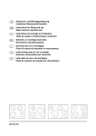
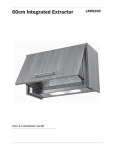
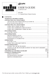
Model#
60255
Use extreme care when
handling especially around the head of the unit.
This appliance MUST be grounded.
* When using outdoors,we recommend using a certified GFI (Ground
Fault Interrupt) outlet to protect against electrical shock.
* Ensure that the heater mounting bracket is SECURELY fastened to the
wall, patio overhang or house eave.
* Route electrical cable AWAY from main body of heater which gets very hot.
* Do NOT cover or obstruct the main body of the heater during use.
* All installations must be in accordance with I.E.E. safety regulations or
equivalent. If you are unsure,consult an electrical service professional.
* Avoid the use of extension cord with this appliance.
* Do not place any objects such as furniture,papers, clothing or curtains
closer than 3 ft to the front and the sides of the heater.
NOTE: your IR heater main body,electrical components & bracket are fully
factory assembled.Do NOT attempt to service or disassemble without proper
instructions.
- IR head unit w/Protective powder coated steel body
Wall Mounting Bracket
Head Unit
with glass plate,
pre-installed, 16/3
grounded electrical
cord, wall mount
component
Grounded Outlet
box cover
Grounding pin
1. Read all instructions before using this heater.
2. This heater will get very hot while in use .To
avoid burning, do not let bare skin touch hot
surface. If provided,use handles when
moving this heater.Keep flammable materials,
such as furniture,pillows,bedding,papers,
clothing, and curtains at least 3 feet (0.9m) from
the heater.
3. DO NOT LEAVE heater unattended.Extreme
caution is necessary when any heater is used
by, or near ,children or disabled persons, and
whenever the heater is left operating and
unattended.
4. Always unplug heater when not in use.
5. Do not operate any heater with a damaged
cord or plug, if the heater malfunctions, or has
been dropped or damaged in any manner.
Return heater to authorized service facility for
repairs.
6. Can be used indoors or outdoors ,operate at
least 3 feet (0.9m) from people or objects.
7. Never operate heater near water or where it
can be knocked over.
8. Do not run cord under carpeting. Do not cover
cord with throw rugs,runners,or similar
coverings. Arrange cord away from traffic area
and where it will not be tripped over.
9. To disconnect heater ,remove plug from
electical outlet.
10. Connect to properly grounded outlets only.
11. Do not insert or allow foreign objects to enter
venilation or exhaust opening;doing so may
cause an electical shock or fire, or may
damage the heater.
12. To Prevent a possible fire, do not block air
intakes or exhaust in any manner. Do not use
on soft surfaces,like a bed ,where openings
may become blocked.
13. A heater has hot and sparking parts inside. Do
not use it in area where gasoline, paint, or
flammable liquids are used or stored.
14. Use this heater only as described in this
manual. Any other use not recommended by
the manufacturer may cause fire, electrical
shock ,or unjury to persons.
15. Avoid the use of an extension cord because
the extension cord may overheat and cause a
risk of fire. However, if you have to use an
extension cord, use either a 12 or 14 gauge
wire which is rated not less then 1900 watts.
The recommended length for a 14 gauge is 050 feet, but if need be long use a 12 gauge no
longer then 100 feet.
16. SAVE THESE INSTRUCTIONS for future
reference.
17. Please keep each side of the head unit at
least 11.8inch from the objects.[Please see the
below illustration.]
Step 1
Be sure to read and familiarize yourself with the overall assembly and installation
instructions in this manual before beginning.It may be helpful to have someone assist
you with the installation. This unit is primarily designed for outdoor applications.
Tools Required: #2 or #3 Phillips Screwdriver (or standard slotted screwdriver),
adjustable wrench, pencil, 5/16'' drill and a ladder.
Step 2
Find a suitable location to mount the heater unit, be sure to comply with ALL minumum
required distances and clearance specifications.See illustration below, fig. 3.
* Do not place any objects such as furniture, papers, clothing or curtains
closer than 3 ft to the front and sides of the heater.
- Position mounting bracket flush against the wall where you want to position the IR unit.
Make sure the bracket is level and mark the centers of the holes with a pencil.
Note the proper upright orientation of the bracket, see fig. 1.
- Drill 4 pilot holes approx. 1 5/8'' deep. For mounting on stucco walls and/or
locations where there is not a wood stud, be sure to use appropriate
wall anchors to properly secure mounting bracket to wall.
- Attached wall bracket using the 4 screws included (and wall anchors if applicable). Apply
all 4 screws loosely at first, check that the bracket is level and then tighten securely.
Step 3
Fig. 2
12"
* Insert wall mount assembly from head unit into wall mount bracket. See fig. 2.
- Note orientation of bracket and head unit.
* Align and apply small set screw to bottom of wall bracket and thru the wall mount of the
head unit to lock head unit into place. Tighten securely.
*** IMPORTANT NOTE: be sure to route and keep the electrical cord
AWAY from the main body of the heater unit. ***
Screws
UP
10"
Drill 5/16"
Pilot hole
1 5/8" depth
84"
Wall
Fig. 2
Floor
Floor
Heater MUST always face the floor
Ceiling
Wall
Route power cord below and away from head unit as show in box 5.
Ceiling
Wall
Correct
Ceiling
UP
Wall
Wrong
Correct
The moving bracket angle may not be more than 45 degrees
Wrong
This appliance MUST be grounded.
* When using outdoors, we recommend using a certified GF I(Ground
Fault Interrupt)outlet to protect against electrical shock.
* Ensure that the heater mounting bracket is SECURELY fastened to the
wall,patio overhang or house eave.
* Route electrical cable AWAY from main body of heater which gets very hot.
* Do NOT cover or obstruct the main body of the heater during use.
* All installations must be in accordance with I.E.E. safety regulations or
equivalent. If you are unsure, consult an electrical service professional.
* Avoid the use of extension cord with this appliance.If one is used,
it MUST be at least a 14/3 wire, grounded cord, 50ft max. length.
* Do not place any objects such as furniture, papers, clothing or curtains
closer than 3 ft to the front and the side of the heater.
NOTE: your IR Heater main body, electrical components & bracket are fully
factory assembled. Do NOT attempt to service or disassemble without proper
instructions.
For optimal performance and safety concerns,we HIGHLY RECOMMEND that the Infrared Heater
Head be operated at a min. of 84''ht. with a 45-55 degree angle of operational spread.
To Adjust The IR Head Unit:
Swivel head unit up or down to desired position. The head unit must be at a 45-55
degree angle for optimal operation and output.There should only be a moderate
amount of tension to maintain the swivel bracket. If it becomes too loose, tighten
hex nuts and bolts at swivel points on head unit bracket.
The adjust angle of Head Unit is less than 45 degree.
Min head unit
clearance from
combustibles
10" wall and
12" ceiling
Note:Be sure electrical cord is grouded and positioned away from head unit.
Creates a
generous zone
of comfort!
Step 1
Before plug your Infrared Heating System, adjust the head unit
angle as desired. Do NOT touch the head unit during operation
or for 30 minutes AFTER unplug.
The head units GETS VERY HOT!
Refer to coverage area in Fig. 7 for best positioning location and heat
spread/coverage.
45 degrees
angle of heat
spread
84"
1500W
Quartz Halogen
Lamp
10ft
Uses standard
120V household
10.8ft
current
19ft
Step 2
The infrared electric heating system comes equipped with a heavy duty ,
16/3 gauge wire and grounded plug. This appliance must be used with an
outlet that has been installed and grounded in accordance with all local
codes and ordinances. Makes sure that the heater is connected to an
outlet having the same configuration as the plug shown in Fig. 8. Do NOT
use an adapter with this product. Check with a licensed electrician if the
grounding instructions are not understood completely or if the wall outlet
does not match the plug.
Grounding instructions
The instruction manual of grounded heaters shall include the following or
equivalent wording: (In the case of a heater rated for a nominal 120 voilts.)
This heater is for use on 120 voits.The cord has a plug as shown at Ain
Figure 65.1 An adapter as shown at C is available for connecting three-blade
grounding-typeplugs to two-slot receptacles.The gree grounding lug extending
from the adapter must be connected to a permanent ground such as a properly
grounded outlet box.The adapter should not be used if a three-slot grounded
receptacle is available.
Step 3
Always UNPLUG unit when not in use!
Your infrared electric heating system is ready to enjoy.Plug the appliance in and begin
enjoying the warmth!
SAFE for INDOOR
Applications too!
Contact toll free customer service hotline to order approved replacement lamps and parts.
NOTE: do NOT touch the new halogen lamp with your bare fingers.Oils from your
hand could reduce the life of the lamp by causing a heat spot.Recommend using
clean cotton or plastic gloves.A clean paper towel may also work.
Quartz Halogen Lamp Replacement:
* Be sure unit is unplugged from wall outlet!
* Remove 2 screws from each end of the head unit as shown in the figure as step 1 and 2
Remove 4 bolts from the front glass plate as shown in step 3
* Pull out & remove the left & right, front air vent panels and protective glass plate.(see #3)
- Note position of end clips on vent panel. They must be aligned as close to end
connectors of lamp tube as possible when re-assembled. Pull out and/or pushed into place.
* Gently pull out entire old lamp assembly from the clips at the terminal connection ends.
(see #4 & #5). Slide and lift the connection ends out from the friction clips by gently pushing apart
the clips. Unscrew wire leads from terminal. Remove entire old lamp assembly.
* Gently re-insert connection ends of the NEW lamp assembly into the friction clips(see #4). Pull
apart the clips slightly and gently push the connectors into place. Do not allow the
metal clips to touch the actual lamp tube. The clips should be about at the center point of the
end connectors.
* Reconnect the wire leads to terminal connectors Re-insert vent panels by gently
pushing the end clips into housing body, align clip ends close to lamp end connectors and push
into place. Insert the 2 screws in each end of the head unit (#1 and #2)
Replace front glass plate ,for best results,insert the 2 bolts for the top of the glass plate first,then
insert the 2 bolts for the bottom of the glass plate Do not tighten until all four bolts are inserted
Do NOT over tighten a gap between the glass and steel housing in necessary for heat venting
Heatproof
casing pipe
Clip ends must be
aligned as close to
end connectors of lamp
tube when installed. Do NOT
allow to touch tube lamp itself.
a casing/
electric wire
Connecting wire
lead
Metal friction clips
Push apart sligtly
to remove
lamp tube end
connectors
4 small
bolts
Remove & Replace ENTIRE Lamp assembly
including lamp, end connectors & wire lead
NOTE: do NOT allow any metal to contact actual lamp tube
Gently re-insert connector
ends of the NEW lamp
assembly into the friction
clips (see #4). Pull apart the
clips slightly and gently push
the connectors into place. Do
not allow the metal clips to
touch the actual lamp tube.
The clips should be about at
the center point of the end
connectors when
re-assembled.
R
Fire Sense R and Well Traveled Living R are registered trademarks of Well Traveled Imports, lnc
. All assembly instruction presentation
s are the property of Well
Traveled Imports, lnc.R and are protected by U.S.
copyrights and trademarks. All rights reserved.