1
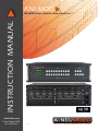
ANI-MOD
INSTRUCTION MANUAL
ANI-MOD Series: Modular Matrix Switcher
A-NeuVideo.com
Frisco, Texas 75034
(317) 456-2461
V3.5
AUDIO / VIDEO MANUFACTURER
SAFETY INFORMATION
1. To ensure the best results from this product, please read this manual and all other documentation before operating your equipment.
Retain all documentation for future reference.
2. Follow all instructions printed on unit chassis for proper operation.
3. To reduce the risk of fire, do not spill water or other liquids into or on the unit, or operate the unit while standing in liquid. Keep unit
protected from rain, water and excessive moisture.
4. Make sure power outlets conform to the power requirements listed on the back of the unit before connecting.
5. Do not attempt to clean the unit with chemical solvents or aerosol cleaners, as this may damage the unit. Dust with a clean dry cloth.
6. Do not use the unit if the electrical power cord is frayed or broken. The power supply cords should be routed so that they are not
likely to be walked on or pinched by items placed upon or against them, paying particular attention to cords and plugs, convenience
receptacles, and the point where they exit from the appliance.
7. Do not force switched or external connections in any way. They should all connect easily, without needing to be forced.
8. Always operate the unit with the AC ground wire connected to the electrical system ground. Precautions should be taken so that the
means of grounding of a piece of equipment is not defeated.
9. AC voltage must be correct and the same as that printed on the rear of the unit. Damage caused by connection to improper AC
voltage is not covered by any warranty.
10. Turn power off and disconnect unit from AC current before making connections.
11. Never hold a power switch in the “ON” position.
12. This unit should be installed in a cool dry place, away from sources of excessive heat, vibration, dust, moisture and cold. Do not use
the unit near stoves, heat registers, radiators, or other heat producing devices.
13. Do not block fan intake or exhaust ports. Do not operate equipment on a surface or in an environment which may impede the normal
flow of air around the unit, such as a bed, rug, carpet, or completely enclosed rack. If the unit is used in an extremely dusty or smoky
environment, the unit should be periodically “blown free” of foreign dust and matter.
14. To reduce the risk of electric shock, do not remove the cover. There are no user serviceable parts inside. Refer all servicing to
qualified service personnel.
15. When moving the unit, disconnect input ports first, then remove the power cable; finally, disconnect the interconnecting cables to
other devices.
16. Do not drive the inputs with a signal level greater than that required to drive equipment to full output.
17. The equipment power cord should be unplugged from the outlet when left unused for a long period of time.
18. Save the carton and packing material even if the equipment has arrived in good condition. Should you ever need to ship the unit,
use only the original factory packing.
19. Service Information Equipment should be serviced by qualifier service personnel when:
A. The power supply cord or the plug has been damaged.
B. Objects have fallen, or liquid has been spilled into the equipment.
C. The equipment has been exposed to rain
D. The equipment does not appear to operate normally, or exhibits a marked change in performance
E. The equipment has been dropped, or the enclosure damaged.
THIS SAFETY INFORMATION IS OF A GENERAL NATURE AND MAY BE SUPERSEDED BY INSTRUCTIONS CONTAINED WITHIN THIS MANUAL
A NEUVIDEO
TABLE OF CONTENTS
CONTENTS
Package Contents .........................................................................1
SAFETY PRECAUTIONS
Introduction / Features ....................................................................2
Please read all instructions before attempting to unpack, install or
operate this equipment and before connecting the power supply.
Please keep the following in mind as you unpack and install this
equipment:
• Always follow basic safety precautions to reduce the risk of fire,
electrical shock and injury to persons.
• To prevent fire or shock hazard, do not expose the unit to rain,
moisture or install this product near water.
• Never spill liquid of any kind on or into this product.
• Never push an object of any kind into this product through any
openings or empty slots in the unit, as you may damage parts
inside the unit.
• Do not attach the power supply cabling to building surfaces.
• Use only the supplied power supply unit (PSU). Do not use the
PSU if it is damaged.
• Do not allow anything to rest on the power cabling or allow any
weight to be placed upon it or any person walk on it.
• To protect the unit from overheating, do not block any vents or
openings in the unit housing that provide ventilation and allow for
sufficient space for air to circulate around the unit.
Specifications .................................................................................3
Main Unit ......................................................................................3
Changeable Cards ......................................................................3
Front Panel Operation ....................................................................4
ANI-MOD88 ..................................................................................4
ANI-MOD ......................................................................................5
Front Panel Control ........................................................................6
Changeable Cards Introduction & Installation ...............................7
ANI-IN-DVI & ANI-OUT-DVI ...............................................7
ANI-IN-VGA & ANI-OUT-VGA ...........................................8
ANI-IN-SDI & ANI-OUT-SDI .............................................10
ANI-IN-HDBT-4K & ANI-OUT-HDBT-4K .........................11
ANI-IN-HDMI-4K & ANI-OUT-HDMI-4K ...........................12
ANI-IN-4K2KF & ANI-OUT-4K2KF ...................................13
ANI-MOD88 AUDIO CARD ..............................................14
System Connection ......................................................................15
Remote Control ............................................................................16
RS-232 Control ...........................................................................17
Connection of RS-232 Communication Port ............................17
Remote Command System from a Personal Computer ...........18
DISCLAIMERS
RS-232 Commands .....................................................................19
The information in this manual has been carefully checked and
is believed to be accurate. We assume no responsibility for any
infringements of patents or other rights of third parties which may
result from its use.
Communication Protocol Command and Command Codes .......21
TCP/IP Control .............................................................................23
GUI Interface ...............................................................................25
Safety Operation Guide ................................................................27
We assume no responsibility for any inaccuracies that may be
contained in this document. We make no commitment to update or
to keep current the information contained in this document.
Troubleshooting & Maintenance ...................................................27
Dear Customer
We reserve the right to make improvements to this document and/
or product at any time and without notice.
Thank you for purchasing this product. For optimum performance
and safety, please read these instructions carefully before
connecting, operating or adjusting this product. Please keep this
manual for future reference.
COPYRIGHT NOTICE
No part of this document may be reproduced, transmitted,
transcribed, stored in a retrieval system, or any of its part translated
into any language or computer file, in any form or by any means
— electronic, mechanical, magnetic, optical, chemical, manual, or
otherwise — without the express written permission and consent.
PACKAGE CONTENTS
Before connecting the unit, it is necessary to unpack it from the
shipping carton and inspect the unit for any damage. While the
cards are hot-swappable, it is recommended to install the cards
before connecting the unit. This will make the installation easier.
•
•
•
•
•
•
ANI-MOD Modular Matrix Switcher (w/ empty slot & empty cover)
RS-232 cable
IR remote w/ battery
(4) Plastic cushions
Power Cord
User Manual
© Copyright 2015. All Rights Reserved.
Version 3.5 MAY 2015
Series 2015V2.3
TRADEMARK ACKNOWLEDGMENTS
All products or service names mentioned in this document may be
trademarks of the companies with which they are associated.
1
A NEUVIDEO
INTRODUCTION & FEATURES
INTRODUCTION
A-Neuvideo’s ANI-MOD series is a high-performance video and audio modular matrix switcher supporting up to 64 input and 64 output signal
sources. It supports different video signals with cross switching. Every video or audio signal is transmitted and switched independently to
decrease signal attenuation. ANI-MOD supports various changeable cards including HMDI, DVI, VGA, SDI and HDBaseT™ etc, and all
the cards support hot plug & play. Users can choose to insert different signal cards for different applications.
The ANI-MODs have a power fail memory function and audio can break away from or follow the video to switch. It has RS-232 port for
serial control and optional IP port for TCP/IP control, can be easily controlled by third-part devices.
With its flexible design, ANI-MOD can be used for different project and tend to be an all-in-one solution. It is the combo solution for
multimedia conference rooms, control rooms, broadcasting rooms, shopping center etc. It will handle all the audiovisual management,
including the switching, driving, scaling etc.
ANI-MOD Modular Matrix Switcher Models
Models
Height
Maximum Slot
Power supplies
RS-232 control
Audio I/O
Network control
ANI-MOD88
2U
2 input card slots &
2 output card slots
Single
ü
Yes*
Optional
ANI-MOD1616
3U
4 input card slots &
4 output card slots
Dual
ü
No
Optional
ANI-MOD3232
5U
8 input card slots &
8 output card slots
Dual
ü
No
Optional
ANI-MOD6464
10U
16 input card slots &
16 output card slots
Dual
ü
No
Optional
*The ANI-MOD88 is unique in this series in that it comes with (8) channel audio input and output cards already installed. This card is not
available as a separate card for installation into the other chassis. Of the video formats which the ANI-MOD Matrix series is able to convert,
the only ones which contain integral audio are HDMI, VGA and HDBaseT™. All other video formats do not contain integral audio channels.
FEATURES
• Modular chassis with configurable I/O slots, ranging from 4x4 to 64x64
• Various I/O cards, includes HDMI, HDBaseT™, SD/HD/3G-SDI, DVI and VGA cards (Compatible with YUV, YC, CVBS & CVBC) to
configure any matrix
• Truly cross-point switching, any input to any output, regardless of signal format
• Supports HDMI1.4a, supports 3D & HDCP compliant
• Integrated HDBaseT™ technology
• Controllable via front panel push buttons, RS-232 & optional TCP/IP, also compatible with 3rd party controlers
• LCD display
2
A NEUVIDEO
SPECIFICATIONS
Main Unit
Control Parts
General
Serial Control Port
RS-232, 9-pin female D connector
Power Supply
100VAC ~ 240VAC, 50/60Hz
Installation
Rack Mountable
Temperature
14~104°F (-10 ~+40°C)
Pin Configurations
2 = TX, 3 = RX, 5 = GND
Power Consumption
200W (max)
Front panel control
Buttons
Humidity
10% ~ 90%
Options
TCP/IP control by external device. Switcher does not
include a build-in web server.
Case Dimension (WxHxD)
Product Weight
ANI-MOD88
19 x 3.5 x 12.6 in (483x88x320mm) (2U high)
6.6 lb (3Kg)
ANI-MOD1616
19 x 5.25 x 12.6 in (483x133x320mm) (3U high)
7.7 lb (3.5Kg)
ANI-MOD3232
19 x 8.7 x 12.6 in (483x222x320mm) (5U high)
11 lb (5Kg)
ANI-MOD6464
19 x 17.25 x 12.6 in (483x438x320mm) (10U high)
17.6 lb (8Kg)
While cable distance is dependent on the quality of the cable that you use and the resolution, here is a general reference:
Cable
Distance
HDMI
50 feet
15M
VGA
65 feet
20M
DVI
23 feet
7M
HDBaseT™
230 feet
70M
ANI-MOD signal card (changeable cards)
The ANI-MOD series input and output cards for installation into the modular matrix switcher chassis are classified into the following models.
ANI-MOD Input cards
Models
ANI-MOD Output cards
INPUTS
Signal Format
Models
OUTPUTS
Signal Format
ANI-IN-DVI
4
DVI
ANI-OUT-DVI
4
DVI
ANI-IN-VGA
4
VGA & STEREO audio
ANI-OUT-VGA
4 VGA,
4 Stereo
audio
VGA & analog audio
ANI-IN-SDI
4 Inputs &
4 LOOP
Outputs
for each
channel)
SDI
ANI-OUT-SDI
4 Outputs
& 4 LOOP
Outputs
for each
channel)
SDI
ANI-IN-HDMI-4K
4
HDMI & STEREO
Audio
ANI-OUT-HDMI-4K
4
HDMI & STEREO
Audio
ANI-IN-4K2KF
4
Optical Fiber
ANI-OUT-4K2KF
4
Optical Fiber
ANI-IN-HDBT-4K
4
HDBaseT™, RS-232,
Audio
ANI-OUT-HDBT-4K
4
HDBaseT™, RS-232,
Audio
3
A NEUVIDEO
ani-mod88
Front Panel Operation
ANI-MOD88: The front panel of ANI-MOD88 is shown as below.
r
w
q
e
y
t
1. IR: IR sensor, receive IR signal sent from IR remote
2. Power Indicator: Illuminate red once powered on
3. LCD Screen: Display real-time operation status
4. INPUTS: Buttons for input channels with green back-light indicating, ranges from 1~ 8, (8) selectable channels in total
5. OUTPUTS: Buttons for output channels with green back-light indicating, ranges from 1 ~ 8, (8) selectable channels in total
6. MENU AV: Transfer video and audio signal synchronously
VIDEO: Transfer video signal only
AUDIO: Transfer video signal only
ALL: Select all input/output channel
THROUGH: To transfer the signals directly to the corresponding output channels
UNDO: Undo button, to resume to the status before the command just performed
: Backspace - to backspace the latest press
←
BACK Panel Operation
e
r
y
t
q
w
u
1. INPUTS: Audio input slot
2. OUTPUTS: Audio output slot
3. INPUTS: Input signal card slots, (2) in total
4. OUTPUTS: Output signal card slots, (2) in total
5. Power Ports: Connect with household alternating current power
6. RS-232: Serial control port, connect with RS-232 port of control device
7. GND Connector: Used for system grounding
8. TCP/IP (Optional): Used for TCP/IP control port
Note: There are only (2) input and (2) output slots for ANI-MOD88, which enables only (2) input cards and (2) output cards to be
installed. The input/output cards can be changed based on your requests and supports hot plug and play.
4
A NEUVIDEO
FRONT & back PANEL
Front Panel Operation
ANI-MOD1616/ANI-MOD3232/ANI-MOD6464: The switcher models ANI-MOD1616, ANI-MOD3232, and ANI-MOD6464 share the same
function buttons, the only difference is the chassis height and number of I/O’s. The front panel of ANI-MOD1616/3232/6464 is shown as below.
r
y
w
q
e
t
1. IR: IR sensor, receive IR signal sent from IR remote
2. Power Indicator: Illuminate red once powered on
3. LCD Screen: Display real-time operation status
4. INPUTS: Buttons for input channels with green back-light indicating, ranges from 0~ 9, 32 selectable channels in total
5. OUTPUTS: Buttons for output channels with green back-light indicating, ranges from 0 ~ 9, 32 selectable channels in total
6. MENU AV: Transfer video and audio signal synchronously
,: division button, to divide the output channels when switching to more than one channel
ENTER: Confirm switching operation. Operation will not be executed by the matrix without confirmation
ALL: To transfer an input channel to all output channels
THROUGH: To transfer the signals directly to the corresponding output channels
UNDO: Undo button, to resume to the status before the command just performed
: Backspace - to backspace the latest press
←
BACK Panel Operation
q
w
e
y
t
r
1. INPUTS: Input signal card slots
2. OUTPUTS: Output signal card slots
3. Power switch: Switch between AC110V and AC230V to access different power
4. Power Ports: Connect with household alternating current power, including one redundant power
5. RS-232: Serial control port, connect with RS-232 port of control device
6. TCP/IP (Optional): Used for TCP/IP control port
5
A NEUVIDEO
FRONT PANEL control
Front Panel Button control
ANI-MOD88
Users can control ANI-MOD88 rapidly and directly with its front panel buttons. Here is a brief operation guide to front panel buttons.
Note:
Format: “Input Channel” + “Switch Mode” +“Output Channel”
1. “Switch Mode”: Audio & Video synchronal (AV) or separate switching mode (Audio/ Video)
2. “Input Channel”: Fill with the number of input channel to be controlled
3. “Output Channel”: Fill with the number of output channels to be controlled. Press “All” to select all the outputs
4. The input/output channels on the rear panel are counting from left to right, top to bottom
5. The input delay time between (2) numbers of every input & output channel must be less than (5) seconds; otherwise the operation
will be cancelled.
Example:
1. To transfer input (1) to output (11), press input “1”, output “0” “1”.
2. To transfer signals from input (1) to all output channels, press buttons in this order: “1”, “All”.
Functional Buttons:
UNDO Button: return to the previous status
Example: Input (6) is connecting with output (6), press input “6” + “AV”+ output 4 to change the connection. Press “Undo” to
enable input (6) to reconnect with output (6).
← Button: If you press buttons “1”, “AV”, “2”, “←” in order, then “2” will be canceled.
THROUGH Button: get straight I/O connection, e.g. input 1 > output 1, input 2 > output 2. Press “Input Channel”+”Through”
Example: If you press buttons “ALL”, “THROUGH” in order, then the result will be like input 1 > output 1, input 2 > output 2,
input 3 > output 3 … input 8 > output 8.
ANI-MOD
Users can control the ANI-MOD rapidly and directly with its front panel buttons. To switch AV/ A/ V signal, please operate the buttons under
the following format:
Note:
Format: “Input Channel” + “AV” +“Output Channel”+“Enter”
1. “Switch Mode”: Audio & Video synchronal (AV) or separate switching mode (Audio/ Video)
2. “Input Channel”: Fill with the number of input channel to be controlled
3. “Output Channel”: Fill with the number of output channels to be controlled. Press “All” to select all the outputs
4. “,” Button: Use to separate multiple I/O channels, and press “ENTER” button to confirm the operation
5. The input/output channels on the rear panel are counting from left to right, top to bottom.
6. The input delay time between (2) numbers of every input & output channel must be less than (5) seconds; otherwise the operation
will be cancelled.
Example:
1. To transfer input (1) to output (11), press input “1”, output “0” “1”.
2. To transfer signals from input (1) to all output channels, press buttons in this order: “1”, “All”.
Functional Buttons:
UNDO Button: return to the previous status
Example: Status 1: Input 6 > output 6
Press input “6” + “AV”+ output 4 to change the connection. Press “Undo” to return to Status 1.
← Button: Backspace the last operation
Example: If you press buttons “1”, “AV”, “2”, “←” in order, then “2” will be canceled.
THROUGH Button: Get straight I/O connection, e.g. input 1 > output 1, input 2 > output 2. Format: “Input Channel”+”Through”
Example: If you press buttons “ALL”, “THROUGH” in order, then the result will be like input 1 > output 1, input 2 > output 2,
input 3 > output 3 … input 16 > output 16.
6
A NEUVIDEO
CHANGEABLE CARDS
Changeable Cards Introduction & Installation
The various ANI-MOD chassis units are designed to work with various changeable input/ output cards, which can be installed in any ANIMOD empty slot (these cards are hot-swappable). Cards are connection specific, designed to accept signals such as DVI, HDMI, VGA,
HDBaseT™, and SDI.
DVI Card
ANI-IN-DVI & ANI-OUT-DVI
Input
Output
Input
(4) DVI
Output
(4) DVI
Input Connector
Female DB24+5
Output Connector
Female DB24+5
Input Level
T.M.D.S. 2.9V/3.3V
Output Level
T.M.D.S. 2.9V/3.3V
Input Impedance
75Ω
Output Impedance
75Ω
Gain
0 dB
Bandwidth
340 MHz (10.2 Gbit/s)
Video Signal
DVI 1.0/HDMI 1.3 full digital T.M.D.S
signal
Switching Speed
200ns (Max)
Crosstalk
<-50dB@5MHz
Max Time-delay
5nS (±1nS)
EDID and DDC
Supports Extended Display Identification Data (EDID) and Display Data Channel (DDC) data using DVI
and HDMI standards. EDID and DDC signals are actively buffered
HDCP
Compliant with HDCP using DVI and HDMI 1.3 standards
General
• Fully compatible with HDMI 1.3 and HDCP, but does not support analogy signal
• Embedded EDID management technology, supporting DDC
ANI-IN-DVI: Is an input card which accepts a maximum of (4) separate DVI input signals. Input signals can be passed to output devices
through ANI-OUT-DVI, or passed through to other types of outputs, through other output cards in the series.
ANI-OUT-DVI: Is an output card, which provides a maximum of (4) separate DVI output signals. Input signals can come from an ANI-INDVI, or from other kinds of input cards in the series.
Pin Layout of the DVI-I connector (Dual-Link). (Female)
PIN
Function
PIN
Function
PIN
Function
1
T.M.D.S.Data2-
9
T.M.D.S.Data1-
17
T.M.D.S. Data 0-
2
T.M.D.S.Data2+
10
T.M.D.S.Data1+
18
T.M.D.S. Data 0+
3
T.M.D.S. Data 2/4 Shield
11
T.M.D.S.Data1/3 Shield
19
T.M.D.S. Data 0/5 Shield
4
T.M.D.S. Data 4-
12
T.M.D.S.Data3-
20
T.M.D.S.Data5-
5
T.M.D.S. Data 4+
13
T.M.D.S.Data3+
21
T.M.D.S.Data5+
6
DDC Clock
14
+5V Power
22
T.M.D.S. Clock Shield
7
DDC Data
15
Ground (return for +5V,
Hsync and Vsync)
23
T.M.D. S. Clock +
8
Analog Vertical Sync
16
Hot Plug Detect
24
T.M.D.S .Clock-
7
A NEUVIDEO
CHANGEABLE CARDS
VGA Signal Card
ANI-IN-VGA/ANI-IN-VA & ANI-OUT-VGA
Video Input
Video Output
Input
(4) VGA
Output
(4) VGA
Input Connector
Female 15 pin HD
Output Connector
Female 15 pin HD
Input Level
0.5 ~ 2.0Vp-p
Output Level
0.5 ~ 2.0Vp-p
Input Impedance
75Ω
Output Impedance
75Ω
Audio Input
Audio Output
Input
(4) Stereo Audio
Output
(4) Stereo Audio
Input Connector
3P Captive connector
Output Connector
3.5mm Stereo audio connector
CMRR
>90dB @20Hz ~ 20KHz
CMRR
>90dB @20Hz ~ 20KHz
Input Impedance
>10KΩ
Output Impedance
>10KΩ
Gain
0 dB
Bandwidth
350MHz (-3dB), fully load
Video Signal
VGA-UXGA, RGBHV, RGBS, RGsB, RsGsBs, component video, S-video & composite video
Crosstalk
<-50dB@5MHz
EDID and DDC
Supports Extended Display Identification Data (EDID) and Display Data Channel (DDC) data using DVI
and HDMI standards. EDID and DDC signals are actively buffered
HDCP
Compliant with HDCP using DVI and HDMI 1.4a standards
General
Switching Speed
200ns (Max)
• Scales all inputs to 1080p
• Compatible with C-Video, YUV, YC (Factory preset function)
• Supports RGBHV, RGsB, RGBS, RsGsBs, YUV, YC and Composite video
ANI-IN-VGA: Is an input card which accepts a maximum of (4) separate VGA inputs and (4) stereo audio inputs. Input signal can pass to output
device through other output cards in the series. (Resolutions Supported: 1920x1080p; XGA (1024x768); 1280x720p; WXGA (1280x800).
ANI-OUT-VGA: Is an output card, which provides a maximum of (4) separate VGA output signals.
Pin layout of the VGA connectors (female):
PIN
Signal Name
PIN
Signal Name
Pin 1
RED
Pin 9
KEY/PWR
Pin 2
GREEN
Pin 10
GND
Pin 3
BLUE
Pin 11
ID0/RES
Pin 4
ID2/RES
Pin 12
ID1/SDA
Pin 5
GND
Pin 13
HSync
Pin 6
RED_RTN
Pin 14
VSync
Pin 7
GREEN_RTN
Pin 15
ID3/SCL
Pin 8
BLUE_RTN
8
A NEUVIDEO
CHANGEABLE CARDS
Connect the devices via VGA converting cable as shown:
• Connect with Component Video (YPbPr) Source
• Connect with Composite Video (C-VIDEO) Source
*(4) Male VGA to female YPbPr cable (Only included with the ANI-IN-VGA/ANI-IN-VA cards)
*(4) Male VGA to female S-video & RCA (C-video) cable (Only included with the ANI-IN-VGA/ANI-IN-VA cards)
Component Video Dongle
S-Video or Composite Video Dongle
9
A NEUVIDEO
CHANGEABLE CARDS
SDI Signal Card
ANI-IN-SDI & ANI-OUT-SDI
Input
Output
Input
(4) SDI
Output
(4) SDI
Input Connector
Female BNC
Output Connector
Female BNC
Input Level
0.8Vp-p ± 10%
Output Level
0.8Vp-p ± 10%
Input Impedance
75Ω
Output Impedance
75Ω
Gain
Unity
Transmission Distance
300M (Max)
Video Standard
SMPTE 292M, SMPTE 259M, SMPTE 424M, ITU-RBT.601, ITU-RBT.1120
Audio Bits per Sample
18 bits per channel, 2 channels (L, R)
Input Return Loss
< -14dB@1MHz ~ 1.5GHz
Maximum Data Rate
2.97 Gbps
Data Rate Lock
Auto
Data Type
8bit, 10bit
General
• Compatible with various different SDI signal formats, including SD/HD/3G-SDI (adaptive)
• Every port has looping output for local monitoring
ANI-IN-SDI: Is an input card which accepts a maximum of (4) separate SDI input signals. Input signal can be passed to output device
through ANI-OUT-SDI, or passed through other output cards in the series. This card is unique when compared to the other input cards in
that it provides a “through” connection for daisy-chainging video devices. Each input signal can be immediately sent back out (“looping”
it), without switching capability, to go to individual monitors.
ANI-OUT-SDI: Is an output card which provides a maximum of (4) separate SDI output signals. Input signals can come from an ANI-IN-SDI,
or from other kinds of input cards in the series.
The BNC connector is shown as the figure below.
10
A NEUVIDEO
CHANGEABLE CARDS
HDBaseT™ Card
ANI-IN-HDBT-4K & ANI-OUT-HDBT-4K
Input
Output
Input
(4) RJ45
Output
(4) RJ45
Input Connector
Female RJ45 / 3.5mm mini jack for IR
(3) poles captive screw connector
for RS-232
Output Connector
Female RJ45 / 3.5mm mini jack for IR
(3) poles captive screw connector
for RS-232
Input Impedance
75Ω
Output Impedance
75Ω
Gain
0dB ~ 10dB@100MHz
Bandwidth
6.75Gbps
Resolution Range
800x600 ~ 1920x1200
Transmission Distance
70M(Max)
SNR
>70dB@ 100MHz-100M
Return Loss
<-30dB@ 5KHz
THD
< 0.005%@1KHz
Min. ~ Max. Level
< 0.3V ~ 1.45Vp-p
HDMI Standard
Support HDMI1.4 and HDCP
Differential Phasic Error
±10° @ 135MHz_100M
General
•
•
•
•
•
•
Supports hot-plug, HDTV, compatible with HDBaseT™ 1.0, HDMI 1.4a & HDCP 1.4
Wide resolution range from 480p to 4K2K, 1080p 3D compliant
Extends HDBaseT™ signal up to 70M at 1080p or 40M at 4K2K
Bi-directional RS-232 transmission on single cable
Auxiliary audio ports support stereo signal
Embedded EDID management technology
ANI-IN-HDBT-4K: Is an input card which accepts a maximum of input (4) separate HDMI signals. Input signals can be passed to output
devices through ANI-OUT-HDBT-4K, or pass through to other types of output cards in the series. This card needs to work in conjunction
with an ANI-402T HDBaseT™ Transmitter*.
ANI-OUT-HDBT-4K: Is an output card which provides a maximum of (4) separate output signals. Input signals can come from ANI-INHDBT-4K, or from other kinds of input cards in the series. This card needs to work in conjunction with an ANI-402R HDBaseT™ Receiver*.
Provision is made within the card for passing RS-232 and IR over the same CAT5e/6 (or better) cable. These are specific to the HDBaseT™
channel. They do not have to be used for the HDBaseT™ channel to function, but are provided for those situations where they are
needed. Please note that this is separate of the RS-232 and IR channels that are provided for the ANI-MOD Matrix unit’s controls.
Pin layout of the RJ45 connectors: (2) different connection standards can be chosen; connectors on both ends of the same cable should
use the same standard.
TIA/EIA T568A
When using STP, Cable
connectors MUST be
metal, and the shielded
layer of cable MUST
be connected to the
connector’s metal
shell, to well share the
grounding.
TIA/EIA T568B
Pin
Cable color
Pin
Cable color
1
green white
1
orange white
2
green
2
orange
3
orange white
3
green white
4
blue
4
blue
5
blue white
5
blue white
6
orange
6
green
7
brown white
7
brown white
8
brown
8
brown
*For more information on the ANI-402T and ANI-402R please see our website.
11
A NEUVIDEO
CHANGEABLE CARDS
HDMI 4K2K Card
ANI-IN-HDMI-4K & ANI-OUT-HDMI-4K
Video Input
Audio Input
Input
(4) HDMI
Input
(4) Analog
Input Connector
Female HDMI
Input Connector
3.5mm pluggable terminal block
Min.~ Max. Level
T.M.D.S. 2.9V~3.3V
Input Impedance
75Ω
Input Impedance
100Ω (Differential)
Frequency Response
20Hz~20KHz
Video Output
Audio Output
Output
(4) HDMI
Output
(4) Stereo
Output Connector
Female HDMI
Output Connector
3.5mm Stereo audio connector
Min.~ Max. Level
T.M.D.S. 2.9V~3.3V
Output Impedance
75Ω
Output Impedance
100Ω (Differential)
Frequency Response
20Hz~20KHz
Gain
0dB ~ 10dB@100MHz
Bandwidth
6.75Gbps
Max Resolution
4K2K
Crosstalk
<-50dB@5MHz
Transmission Distance
1080p ≤ 70M / 4K2K ≤ 40M
Switching Speed
200ns (Max)
Work Temperature
-10°C~ +40°C
Reference Humility
10%~90%
SNR
>70dB@100MHz-100M
Return Loss
<-30dB@ 5KHz
Supported Audio Format
Embedded HDMI Audio: Stereo, Dobly Digital, DTS, DTS-HD / Analog Audio: Stereo only
HDMI Standard
Supports HDMI 1.4& DVI 1.0
DID& HDCP
Management
Compliant with HDCP 1.4 / Supports manual EDID management
General
•
•
•
•
•
Supports hot-plug, HDMI 1.4 & HDCP 1.4 compliance
Compatible with DVI signal
Supports high-definition HDMI source up to 4K2K, 1080p 3D compliance
Provides auxiliary audio port as supplement to HDMI embedded audio
Embedded EDID management technology
ANI-IN-HDMI-4K: Is an input card which accepts a maximum of input (4) separate HDMI signals. Input signals can be passed to output
devices through ANI-OUT-HDMI-4K, or pass through to other types of output cards in the series.
ANI-OUT-HDMI-4K: Is an output card which provides a maximum of (4) separate output signals. Input signals can come from ANI-INHDMI-4K, or from other kinds of input cards in the series. HDCP compliant status settable via RS-232 commands.
Pin layout of the HDMI connectors (Female)
PIN
Signal Name
PIN
Signal Name
1
TMDS Data 2+
8
TMDS Data 0 Shield 15
DDC Clock
2
TMDS Data 2 Shield 9
TMDS Data 0-
16
DDC Data
3
TMDS Data 2-
10
TMDS Clock+
17
Ground
4
TMDS Data 1+
11
TMDS Clock Shield
18
+5V Power
5
TMDS Data 1 Shield 12
TMDS Clock-
19
Hot Plug Detect
6
TMDS Data 1-
13
CEC
20
SHELL
7
TMDS Data 0+
14
No Connect
12
PIN
Signal Name
A NEUVIDEO
CHANGEABLE CARDS
4K2K FIBER Card
ANI-IN-4K2KF & ANI-OUT-4K2KF
Input
Output
Input
(4) Fiber Optical
Output
(4) Fiber Optical
Input Connector
SPF Fiber Optical Connector
Output Connector
SPF Fiber Optical Connector
Fiber Type
Multi-mode, Single mode
Fiber Type
Multi-mode, Single mode
Data Rate
10.2 Gbps
Color Depth
8bit, 10bit, 12bit, 16bit
Work Temperature
0°C~55°C
Reference Humility
10%~90%
Connector
LC connector
Resolution
Up to 4K2K
Transmission Distance
1Km (Single mode transmission, using Single Mode Optical Module and OM3 Single Mode Fiber Cable)
300M (Multi-mode transmission, using Single/ Multi mode Optical Module and OM3 Multi-Mode Fiber Cable)
Data Rate
10.2Gbit/s
General
Optical Fiber Mode
•
•
•
•
Support hot-plug; High bandwidth: 10.2Gbps
Compliant with HDMI 1.4
Capable to transmit 4K2K & 1080p 3D (max) signals
Supports multi-mode transmission up to 300m and single mode transmission up to 1Km
ANI-IN-4K2KF: Is an input card which accepts a maximum of input (4) separate signals. Corresponding indicator illuminates green when
there is an input signal. Input signals can come from ANI-OUT-4K2KF, or from other kinds of output cards in the series.
ANI-OUT-4K2KF: Is an output card which provides a maximum of (4) separate output signals. Input signals can come from ANI-IN4K2KF, or from other kinds of input cards in the series. Corresponding indicator illuminates green when there is output signal.
Note: Use the ANI-IN-4K2KF & ANI-OUT-4K2KF with an optical fiber transmitter/receiver.
13
A NEUVIDEO
AUDIO CARDS
AUDIO Card
ANI-MOD88 Only
Input
Output
Input
(8) stereo
Output
(8) stereo
Input Connector
3.5mm captive screw connectors (5) pole Output Connector
3.5mm captive screw connectors (5) pole
Input Impedance
>10KΩ
Output Impedance
50Ω
Frequency Response
20Hz~20KHz, ±0.5dB
CMRR
>90dB@20Hz~20KHz
Stereo Channel
Separation
>80dB@1KHz
THD + Noise
1% @1KHz
0.3%@20KHz at nominal level
General
• 8x8 stereo audio cross point switching card
• Supports the balanced/unbalanced audio, by different connection
• It is NOT a hot plug card, fixed on the chassis
Balanced Audio Connection:
Unbalanced Audio Connection:
14
A NEUVIDEO
REMOTE CONTROL
IR Remote control
With the IR remote, ANI-MOD could be controlled remotely. As the function buttons on the IR remote are the same with the ones on the front
panel, the IR remote shares the same operations and commands with the control panel.
Press the buttons under below format:
“Input Channel” + “Switch Mode” +“Output Channel”
Input channel
buttons,
including 1~10+
Menu buttons,
including
switching buttons
and function
buttons
Output channel
buttons,
including 1~10+
15
A NEUVIDEO
System Connection
Usage Precautions
1. System should be installed in a clean environment and has a prop temperature and humidity.
2. All of the power switches, plugs, sockets and power cords should be insulated and safe.
3. All devices should be connected before power on.
Connection Diagram
Application
ANI-MOD series has a good application in various occasions, such as radio & television, multi-media meeting room, big screen displaying,
television education and command & control center etc.
16
A NEUVIDEO
RS-232 Control
Connection of RS-232 Communication Port
Besides the front control panel and IR remote, the ANI-MOD can also be controlled by far-end control system or through the Ethernet
control via the RS-232 communication port. This RS-232 communication port is a female 9- D connector. The definition of its pin layout
is shown in the table below.
No.
Pin
Function
1
N/u
Unused
2
Tx
Transmit
3
Rx
Receive
4
N/u
Unused
5
Gnd
Ground
6
N/u
Unused
7
N/u
Unused
8
N/u
Unused
9
N/u
Unused
When the ANI-MOD connects to the RS-232 port of a computer with control software, users can control it by that computer. To control the
switcher, users need to use RS-232 control software. www.a-neuvideo.com/shop/download/ANI-MOD.zip
17
A NEUVIDEO
RS-232 Control
Remote Command System from a Personal Computer
The ANI-MOD Matrix series can be controlled remotely from a personal computer. The control signal is brought into the ANI-MOD Matrix
through the RS-232 connector on the back panel of the unit. The commands are input through software that comes with the ANI-MOD
Matrix, once installed in the computer.
RS-232 Cable Pins Used
Communications Protocol:
1. Transmission Rate: 9600 bps
2. Data Format: 8 data bits, No parity , 1 start bit, and 1 stop bit
3. Flowing Control: None
Also known as: 9600,8,n,1
Proper settings for the computer’s communication protocol are shown in the screen shots below:
18
A NEUVIDEO
RS-232 COMMANDS
RS-232 Communication Commands
With this command system, users are able to control and operate theANI-MOD with RS-232 software remotely.
Communication protocol: Baud rate: 9600; Data bit: 8; Stop bit: 1; Parity bit: none.
Command Types
Command Codes
Functions
Commands for Main Unit
/*Type;
Inquire the models information.
/%Lock;
Lock the keyboard of the control panel on the Matrix.
/%Unlock;
Unlock the keyboard of the control panel on the Matrix.
/^Version;
Inquire the version of firmware
/:MessageOff;
Turn off the feedback command from the com port. It will only show the “switcher OK”.
/:MessageOn;
Turn on the feedback command from the com port.
Undo.
To cancel the previous operation.
Demo.
Switch to the “demo” mode, 1>1, 2>2, 3>3 … and so on.
[x]All.
Transfer signals from the input channel [x] to all output channels
All#.
Transfer all input signals to the corresponding output channels respectively.
All$.
Switch off all the output channels.
[x]#.
Transfer signals from the input channel [x] to the output channel [x].
[x]$.
Switch off the output channel [x].
All@.
Switch on all the output.
[x]@.
Switch on output [x].
[x1]V[x2].
Transfer the video signals from the input channel [x1] to the output channel [x2].
[x1]A[x2].
Transfer the audio signals from the input channel [x1] to the output channel [x2].
[x1]B[x2].
Transfer signal from the input channel [x1] to the output channel [x2].
Status[x].
Inquire the input channel to the output channel [x].
Status.
Inquire the input channel to the output channels one by one.
Save[Y].
Save the present operation to the preset command [Y]. [Y] ranges from 0 to 9.
Recall[Y].
Recall the preset command [Y].
Clear[Y].
Clear the preset command [Y].
PWON.
Work normally.
PWOFF.
Enter in standby mode.
HDCPON.
Turn on the HDCP output.
HDCPOFF.
Turn off the HDCP output.
/V00.
Inquire the version of backboard software.
UpgradeIntEDID[x].
Upgrade built-in EDID data. Supports 6 types of EDID data (see Note 6). When the
switcher gets the command, it will show a message to send EDID file (.bin file).
EDIDUpgrade[x].
Upgrade EDID data of input ports. When the switcher gets the command, it will show a
message to send EDID file (.bin file). Operations will be canceled after 10 seconds.
EDID/[x]/[y].
Set the EDID data of input port [x] to built-in EDID data of type [y].
The value of [y] varies from 1~6. The EDID data types are same as mentioned above.
EDIDG[x].
Get EDID data from output channel X and display the data on serial port control
software. [x] is the output port number.
EDIDMInit.
Recover the factory default EDID data for every input channel.
EDIDM[X]B[Y].
Manually EDID switching. Enable input [Y] to learn the EDID data of output[X]. If there is
problem learning the EDID data, it will automatically set the default EDID data for input [Y].
USER/[Y]/[X]:*****;
Custom command for signal cards, [Y]=I/O; [X]= port number; *****: User-definable
command, e.g. 0623%
0911%.
Restore factory default. All I/O connection will be restored to straight through: 1>1,
2>2,…; saved operation status will remain the same.
19
A NEUVIDEO
RS-232 CommandS
ANI-IN-DVS
Command Types
Command Codes
Functions
Commands for
Signal Cards
USER/I/[x]:02xx%;
Set the brightness of input [x] to xx, xx=00~99
USER/I/[x]:03xx%;
Set the contrast of input [x] to xx, xx=00~99
USER/I/[x]:04xx%;
Set the saturation of input [x] to xx, xx=00~99
USER/I/[x]:05xx%;
Set the sharpness of input [x] to xx, xx=00~99
USER/I/[x]:0606%;
(For 4I-DS/ VA) Auto-adjust VGA input signal
USER/I/[x]:0607%;
Set picture’s color temperature
USER/I/[x]:0608%;
Configure image scale
USER/I/[x]:0614%;
Configure picture mode
USER/I/[x]:0617%;
Restore input [x] to factory default.
USER/I/[x]:0619%;
Set the resolution of input [x] to 1360x768, HD
USER/I/[x]:0626%;
Set the resolution of input [x] to 1024x768, XGA
USER/I/[x]:0627%;
Set the resolution of input [x] to 1280x720, 720P
USER/I/[x]:0628%;
Set the resolution of input [x] to 1280x800, WXGA
USER/I/[x]:0629%;
Set the resolution of input [x] to 1920x1080, 1080P
USER/I/[x]:0620%;
Set the resolution of input [x] to 1920x1200, WUXGA
USER/I/[x]:0621%;
Set the resolution of input [x] to 1600x1200, UXGA
USER/I/[x]:0698%;
Software update
USER/I/[x]:0686%;
Set the output signal of input [x] to HDMI
USER/I/[x]:0687%;
Set the output signal of input [x] to DVI
ANI-OUT-DVS
Command Types
Command Codes
Functions
Commands for
Signal Cards
USER/O/[x]:0201%;
Set the input source of output [x] to YPbPr
USER/O/[x]:0202%;
Set the input source of output [x] to VGA
USER/O/[x]:0203%;
Set the input source of output [x] to C-VIDEO
USER/O/[x]:0804%;
Set the resolution of output [x] to 1280x720P @60Hz
USER/O/[x]:0813%;
Set the resolution of output [x] to 1280x1080P @60Hz
USER/O/[x]:0824%;
Set the resolution of output [x] to 1024x768 @60Hz
USER/O/[x]:0826%;
Set the resolution of output [x] to 1280x1024 @60Hz
USER/O/[x]:0837%;
Set the resolution of output [x] to 1920x1200 @60Hz
USER/O/[x]:0106%;
Switch on the HDCP compliance of output [x]
USER/O/[x]:0107%;
Switch off the HDCP compliance of output [x]
GetResolution[x].
Capture output resolution of output [x]
GetVGAPortMode[x].
Inquire the output status of VGA port [x]
USER/O/[x]:0617%;
Restore output [x] to factory default.
20
A NEUVIDEO
RS-232 CommandS
ANI-IN-VA
Command Types
Command Codes
Functions
Commands for
Signal Cards
USER/I/[x]:0622%;
Set the signal of input channel [x] to VGA.
USER/I/[x]:0623%;
Set the signal of input channel [x] to YCBCR.
USER/I/[x]:0624%;
Set the signal of input channel [x] to SVIDEO.
USER/I/[x]:0625%;
Set the signal of input channel [x] to CVIDEO.
USER/I/[x]:0626%;
Set the resolution of input [x] to 1024x768@60Hz.
USER/I/[x]:0627%;
Set the resolution of input [x] to 1280X720@60Hz.
USER/I/[x]:0628%;
Set the resolution of input [x] to 1280X800@60Hz.
USER/I/[x]:0619%;
Set the resolution of input [x] to 1360X768@60Hz.
USER/I/[x]:0621%;
Set the resolution of input [x] to 1600X1200@60Hz.
USER/I/[x]:0629%;
Set the resolution of input [x] to 1920X1080@60Hz.
USER/I/[x]:0620%;
Set the resolution of input [x] to 1920X1200@60Hz.
USER/I/[x]:0617%;
Restore input [x] to factory default.
USER/I/[x]:0606%;
Auto-adjust VGA signal
USER/I/[x]:0698%;
Update software
ANI-IN-HDBT-4K / ANI-IN-HDMI-4K
Command Types
Command Codes
Commands for
Signal Cards
AUDIO[X]I[Z].
Functions
X is the input port.
Z is 0 or 1 (0 means select HDMI embedded audio, 1 means select external audio)
For example, when useing ANI-IN-HDMI-4K input card plugged in to slot number (2).
Sending the command “AUDIO6I1.” to the matrix will select Input Channel 6, External
audio.
When using ANI-IN-HDBT-4K input card, plugged in to the first slot. Sending command
“AUDIO3I0.” to the matrix will select Input Channel 3, HDMI embedded audio.
21
Communication Protocol
and Command Codes
A NEUVIDEO
Note:
1. Please disconnect all the twisted pairs before sending command EDIDUpgrade[X].
2. In above commands, “[”and “]” are symbols for easy reading and do not need to be typed in actual operation.
3. Please remember to end the commands with the ending symbols “.” or “;”.
4. Type the command carefully, it is case-sensitive.
5. Commands pertaining to EDID only avails for signal cards that support EDID management.
6. The switcher boasts 6 in-built EDID data, the chart below illustrates the detailed information:
No.
Detailed Information
1
1080p 2D 5.1CH
2
1080p 2D 2.0CH
3
720p 2D 5.1CH
4
720p 2D 2.0CH
5
4K2K 2D 5.1CH
6
4K2K 2D 2.0CH
Update in-built EDID data by sending command UpgradeIntEDID[x]..
Examples:
1. Transfer signals from an input channel to all output channels: [x]All.
Example: Send “3All.” to transfer signals from the input 3 to all output channels.
2. Transfer all input signals to corresponding output channels respectively: All#.
Example: If this command is carried out, the status of matrix will be: 1->1, 2->2, 3->3, 4->4…… 8->8….
3. Switch off all the output channels: All$.
Example: After running this command, there will be no signals on all the outputs.
4. Switch off the detail feedback command from the COM port: /:MessageOff;
But, it will leave the “switch OK” as the feedback, when you switch the matrix.
5. Switch on the detail feedback command from the COM port: /:MessageOn;
It will show the detail switch information when it switch. Example: when switch 1->2, it will feedback “AV01 to 02”.
6. Transfer signals from an input channel to corresponding output channel: [x]#.
Example: “5#.” to transfer signals from the input5 to the output5.
7. Switch off an output channel: [x]$.
Example: “5$.” to switch off the output 5.
8. Switch signal: [x1] B[x2].
Example: “12B12,13,15.” to transfer signal from the input12 to the output No.12,13,15.
9. Inquire the input channel to the output channel [x]: Status[x].
Example: Send “Status3.” to inquire the input channel to the output 3.
10. Inquire the input channel to the output channels one by one: Status.
Example: “Status.” to inquire the input channel to the output channels one by one.
11. Save the present operation to the preset command [Y]: Save[Y].
Example: “Save7.” to save the present operation to the preset command No.7.
12. Recall the preset command [Y]: Recall[Y].
Example: “Recall5.” to recall the preset command No.5.
13. Clear the preset command [Y]: Clear[Y].
Example: “Clear5.” to clear the preset command No.5.
14. EDID management command:. EDIDM[X]B[Y].
Example: “EDIDM5B3.” to enable input 3 to learn the EDID data of output 5.
15. Command for signal cards: USER/[Y]/[X]*****.
Example: “USER/I/7:0623%;” to set the input 7 to support YPbPr signal, the card is plugged in the second input slot of the matrix.
22
A NEUVIDEO
TCP/IP Control (OPTIONAL)
MANAGE TCP/IP SETTINGS
TCP/IP default settings: IP is 192.168.0.178, Gateway is 192.168.0.1.
To manage the IP address, you first need a PC that can connect to the same sub-net.
Note that most modern computers will interpret the correct pins when connected in this fashion. Should you experience any
difficulties then you should switch to an Ethernet Crossover cable.
Step1.
Connect a computer to the Ethernet port of the ANI-MOD
Step2.
Set the PC’s IP and gateway to the same sub-net as the default static IP of the ANI-MOD.
• In the example below the IP address is set to 192.168.0.227 and the default gateway is set to 192.168.0.1.
• Ignore DNS server settings.
Same IP as
the switcher
Step3.
Click on OK
Step4. Enter http://192.168.0.178:100 in Internet Explorer, you will see the LOGIN page.
Step5. Enter user name “admin” and password “admin”, then press the Enter button on your keyboard.
Then you can enter the configuration page to configure the IP port.
23
A NEUVIDEO
TCP/IP Control (OPTIONAL)
Step6. Change IP
• Change IP
a) Select the tab “Internet Settings: WAN” to change the IP settings.
b) Press the button Apply to save your settings.
24
A NEUVIDEO
GUI INTERFACE
Set your matrix size (Model Name has no affect)
Control switcher using cross points
25
A NEUVIDEO
GUI INTERFACE
Select from the detected available COM ports
OR
Select connection via TCP/IP
26
A NEUVIDEO
Safety Operation Guide
Troubleshooting & Maintenance
Safety Operation Guide
To insure the best from the product, please read all instructions carefully before using the device. Save this manual for further reference.
• Unpack the equipment carefully and save the original box and packing material for possible future shipment
• Follow basic safety precautions to reduce the risk of fire, electrical shock and injury to persons.
• Do not dismantle the housing or modify the module. It may result in electrical shock or burn.
• Using supplies or parts not meeting the products’ specifications may cause damage, deterioration or malfunction.
• Refer all servicing to qualified service personnel.
• To prevent fire or shock hazard, do not expose the unit to rain, moisture or install this product near water.
• Do not put any heavy items on the extension cable in case of extrusion.
• Do not remove the housing of the device as opening or removing housing may expose you to dangerous voltage or other hazards.
• Install the device in a place with fine ventilation to avoid damage caused by overheat.
• Keep the module away from liquids.
• Spillage into the housing may result in fire, electrical shock, or equipment damage. If an object or liquid falls or spills on to the
housing, unplug the module immediately.
• Do not twist or pull by force ends of the optical cable. It can cause malfunction.
• Do not use liquid or aerosol cleaners to clean this unit. Always unplug the power to the device before cleaning.
• Unplug the power cord when left unused for a long period of time.
• Information on disposal for scrapped devices: do not burn or mix with general household waste, please treat them as normal electrical wastes.
Troubleshooting & Maintenance
Problems
Causes
Solutions
Output image with ghost
Bad quality of the connecting cable
Try another high quality cable
Impropriate image setting of the
displayer
Adjust corresponding image settings
Output image with color losing or
no video signal output
Fail connection
Reconnect the displayer and the matrix
No output image when switching
No signal at the input / output end
Check with oscilloscope or multimeter if there is any signal at
the input/ output end.
Fail or loose connection
Make sure the connection is good
The switcher is broken
Send it to authorized dealer for repairing.
Run out of battery
Change for another battery
IR remote is broken
Send it to authorized dealer for repairing.
Fail connection of power cord.
Make sure the power cord connection is good.
IR remote does not work
POWER indicator doesn’t work or
no respond to any operation
EDID management does not work The HDMI cable is broken at the
normally
output end.
Change for another HDMI cable which is in good working
condition.
There is a blank screen on the
display when switching
The display does not support the
resolution of the video source.
Switch again.
Static becomes stronger when
connecting the video connectors
Bad grounding
Check the grounding and make sure it is connected well.
Cannot control the device by
control device (e.g. a PC) through
RS-232 port
Wrong RS-232 communication
parameters
Type in correct RS-232 communication parameters.
Broken RS-232 port
Send it to authorized dealer for checking.
Cannot control the device by front
panel buttons while can control it
through RS-232 port
The front panel buttons are
locked
Send command 50605% to unlock the front panel buttons.
Cannot control the device by
RS-232 / IR remote / front panel
buttons
The device has already been
broken.
Send it to authorized dealer for repairing.
27
Manage the EDID data manually to make the resolution of
the video source automatically compliant with the output
resolution.
A NEUVIDEO
TERMS AND CONDITIONS OF USE
PLEASE READ THE FOLLOWING TERMS AND CONDITIONS CAREFULLY BEFORE USING THIS HARDWARE, COMPONENTS AND SOFTWARE PROVIDED
BY, THROUGH OR UNDER A-Neuvideo, INC (COLLECTIVELY, THE “PRODUCT”). By using installing or using the Product, you unconditionally signify your
agreement to these Terms and Conditions. If you do not agree to these Terms and Conditions, do not use the Product and return the Product to A-Neuvideo, Inc. at
the return address set forth on the Product’s packing label at your expense. A-Neuvideo, Inc. may modify these Terms and Conditions at anytime, without notice
to you.
Restrictions On Use of the Product
It is your responsibility to read and understand the installation and operation instructions, both verbal and in writing, provided to you with respect to the Product.
You are authorized to use the Product solely in connection with such instructions. Any use of the Product not in accordance with such instructions shall void any
warranty pertaining to the Product. Any and all damages that may occur in the use of the Product that is not strictly in accordance with such instructions shall be
borne by you and you agree to indemnify and hold harmless A-Neuvideo, Inc. from and against any such damage.
The Product is protected by certain intellectual property rights owned by or licensed to A-Neuvideo. Any intellectual property rights pertaining to the Product are
licensed to you by A-Neuvideo, Inc. and/or its affiliates, including any manufacturers or distributors of the Product (collectively, “A-Neuvideo”) for your personal use
only, provided that you do not change or delete any proprietary notices that may be provided with respect to the Product.
The Product is sold to you and any use of any associated intellectual property is deemed to be licensed to you by A-Neuvideo for your personal use only.
A-Neuvideo does not transfer either the title or the intellectual property rights to the Product and A-Neuvideo retains full and complete title to the intellectual property
rights therein. All trademarks and logos are owned by A-Neuvideo or its licensors and providers of the Product, and you may not copy or use them in any manner
without the prior written consent of A-Neuvideo, which consent may be withheld at the sole discretion of A-Neuvideo.
The functionality and usability of the Product is controlled by A-Neuvideo, Inc. from its offices within the State of Texas, United States of America. A-Neuvideo makes
no representation that materials pertaining to the Product are appropriate or available for use in other locations other than the shipping address you provided with
respect thereto. You are advised that the Product may be subject to U.S. export controls.
Disclaimers and Limitation of Liability
A-Neuvideo may change or modify the Product at any time, from time to time.
THE PRODUCT IS PROVIDED “AS IS” AND WITHOUT WARRANTIES OF ANY KIND EITHER EXPRESS OR IMPLIED. A-Neuvideo DOES NOT WARRANT OR
MAKE ANY REPRESENTATIONS REGARDING THE USE OR THE RESULTS OF THE USE OF THE PRODUCT’S CORRECTNESS, ACCURACY, RELIABILITY,
OR OTHERWISE.
A-Neuvideo has no duty or policy to update any information or statements pertaining to the Product and, therefore, such information or statements should not be
relied upon as being current as of the date you use the Product. Moreover, any portion of the materials pertaining to the Product may include technical inaccuracies
or typographical errors. Changes may be made from time to time without notice with respect to the Product.
TO THE FULLEST EXTENT PERMISSIBLE PURSUANT TO APPLICABLE LAW, A-Neuvideo DISCLAIMS ALL WARRANTIES, EXPRESS OR IMPLIED,
INCLUDING, BUT NOT LIMITED TO IMPLIED WARRANTIES OF MERCHANTABILITY, FITNESS FOR A PARTICULAR PURPOSE AND NON-INFRINGEMENT.
A-Neuvideo DOES NOT WARRANT THE ACCURACY, COMPLETENESS OR USEFULNESS OF ANY INFORMATION WITH RESPECT TO THE PRODUCT.
A-Neuvideo DOES NOT WARRANT THAT THE FUNCTIONS PERTAINING TO THE PRODUCT WILL BE ERROR-FREE, THAT DEFECTS WITH RESPECT TO
THE PRODUCT WILL BE CORRECTED, OR THAT THE MATERIALS PERTAINING THERETO ARE FREE OF DEFECTS OR OTHER HARMFUL COMPONENTS.
A-Neuvideo WILL USE ITS REASONABLE EFFORTS TO CORRECT ANY DEFECTS IN THE PRODUCT UPON TIMELY WRITTEN NOTICE FROM YOU NOT
TO EXCEED 10 BUSINESS DAYS AFTER RECEIPT BY YOU OF THE PRODUCT, BUT YOU (AND NOT A-Neuvideo) ASSUME THE ENTIRE COST OF ALL
NECESSARY SERVICING, REPAIR AND CORRECTION THAT WAS CAUSED BY YOU UNLESS OTHERWISE AGREED TO IN A SEPARATE WRITING BY
A-Neuvideo.
UNDER NO CIRCUMSTANCES, INCLUDING, BUT NOT LIMITED TO, NEGLIGENCE, SHALL A-Neuvideo BE LIABLE FOR ANY SPECIAL OR CONSEQUENTIAL
DAMAGES THAT RESULT FROM THE USE OF, OR THE INABILITY TO USE THE PRODUCT IN ACCORDANCE WITH ITS SPECIFICATIONS, EVEN IF
A-Neuvideo OR ITS REPRESENTATIVES HAVE BEEN ADVISED OF THE POSSIBILITY OF SUCH DAMAGES. IN NO EVENT SHALL A-NeuVIDEO’S TOTAL
LIABILITY TO YOU FROM ALL DAMAGES, LOSSES, AND CAUSES OF ACTION (WHETHER IN CONTRACT, OR OTHERWISE) EXCEED THE AMOUNT YOU
PAID TO A-Neuvideo, IF ANY, FOR THE PRODUCT.
END OF DOCUMENT
30