1
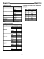
AT6SD
KEYBOARD
CONTROLLER
Instruction manual
(ref. Mi 3146)
Please read carefully and completely this manual before install the product
and keep for future reference
CONTENTS
1. Advisement ………………………………………………………. 4
2. Confirming the Contents of the Package ……………………... 6
3. Main Features and Functions …………………………………. 7
4. Appearance and Function Key ………………………………… 8
5. Functions and Operations ……………………………………. 10
1) Initial Setup of Keyboard
2) Choice of Camera
3) Joystick and the Manual operation of Camera
4) Camera Setup (How to enter into OSD menu)
5) Preset Point
6) Swing
7) Group
8) Tour
9) Spiral Function
10) PTZ trace
11) Camera Remote Reset
12) Brightness Control of LCD
13) Alarm On / Off
6. Maintenance and Mending …………………………………… 19
7. Connections ………………………………………………..…... 20
8. General Specifications ………………………………………… 21
1) Controller
2) Junction box
3) DC Power Supply
4) Camera Control Interface
5) Constitution of Junction box pin
6) Constitution of pin between Controller and Junction box
9. Quick Reference ……………………………………………… 24
2
1. Advisement
CAUTION
WARNING
Always use the unit indoors.
• The unit should never be used outdoors, or in any place where it will be
exposed to rain or other extremes of moisture.
• Direct exposure to water will result in rust and will damage the unit.
Never use in environments that have heavy concentrations of dust,
smoke, steam or humidity.
• Environments such as these could result in fire, electrical shock or other
serious damage or injury.
Never place the unit in extremes of high or low temperatures.
• Extreme temperatures will damage the unit.
• Always use within an operating range of 0 °C to 40 °C.
Never mount in areas exposed to direct sunlight.
• Direct sunlight can also discolor the unit and cause other damage.
Never expose the unit to impact.
• Strong impact may seriously damage the unit.
Always have the unit installed by the store it was purchased from.
• Improper connections and/or installation could result in electrical shack,
fire or other serious injury or damage.
Do not place the unit on an unstable surface.
• Always checks the strength and stability of the installation location.
• A falling unit will result in damage and could cause serious injury
Never disassemble or attempt to repair or modify the unit.
• Disassembly by untrained personnel could result in serious electrical
shock, fire and/or malfunction.
Never use in locations where combustible materials are used.
• The unit should never be used where combustible materials, such as
gases, are being used.
• Fire, explosion or other serious accidents could occur.
Never touch electrical connections with wet hands.
• Touching electrical connections with wet hands could result in serious
electrical shock.
Never expose the unit to water.
• If the unit becomes wet, turn off the power and unplug it immediately.
• Stop using the unit if it becomes wet and contact your nearest dealer.
Never use the unit if there is an abnormality.
• Turn off the power and unplug the unit immediately if there is any type of
abnormality, such as a strange smell or smoke.
• Continuing to use a unit that is not operation properly could result in
serious injury or damage ta the unit.
Always use the designated power supply.
• Failure to use the proper power supply could result in fire, electrical shock,
serious injury and/or damage.
• Always uses the designated power supply.
Always handle the connecting cords properly.
• Never damage or modify the connecting cords.
• Never pull on the connecting cord, expose them to extreme heat and/or
place heavy objects on top of them.
• Failure to follow these warnings could result in fire, electrical shock or
other damage or injury.
FOR PROPER OPERATION
Never install the unit yourself.
• The unit should be installed by trained personnel.
This product has been designed and manufactured in accordance with the
harmonized European standards, following the provisions of the below stated
directives.
Electromagnetic Compatibility Directive 89/336/EEC (EN 61000-3-2:1995,
EN 61000-3-3:1995, EN 50081-1:1992, EN 50082-1:1997).
This devise complies with part 15 of the FCC rules operation is subject to the
following two conditions: (1) This device may not cause harmful interterence
and (2) This device must accept any interference received including
interference that may cause undesired operation.
3
2. Confirming the Contents of the Package.
3. Main Features and Functions
1) Control keyboard unit 1EA.
Synopsis
This controller is for exclusive use for pan / tilt / zoom dome camera
and speed dome camera.
This is able to control a maximum of the 255 cameras, and several
controllers are able to control a camera at the same time.
Dome camera can set and fulfil the surveillance connected with
preset, swing, group and tour.
Features
- Control up to maximum 255 cameras
- Several keyboards can be used to simultaneous control of a
camera
- Easy operation of pan/tilt with the joystick
- Same effect as 64 fixed surveillance camera by setting a
maximum of 64 preset points
- Pan/tilt swing function
- Group surveillance function (select preset points routinely and
repeatedly)
- Tour surveillance function (repeated practice of many groups)
- PTZ (Pan-Tilt-Zoom) trace function
- OSD (On-Screen-Display) function
- Spiral surveillance function
- Easy setup of functions by using LCD (Liquid-Crystal-Diode)
module
2) Junction box 1EA.
3) Connection cable (modular jack) 1EA.
** This keyboard was designed for various applications. So
all the functions described in this manual could not be
available.**
4) Instruction manual.
4
2) Setting method of Junction box
- Camera controls 1
4. Appearance and Function Key
1) Controller function button
ALL Button
Simultaneous on/off of
cameras, lights and AUX1.
(only for receiver unit)
AUX (Auxiliary) Buttons
These buttons are used to control
of Auto-Pan (AUX1) and other unit
(AUX2). (Only for receiver unit).
RUN Button
#
Numeric Keypad (0-9)
These keys are used to
make input for settings and
other functions.
ALARM Buttons
This button is used to on/off of
registered video motion detection.
HOLD Button
#
This is the input and output terminal. Connect 485+ to data + and 485–
to data –.
When you communicate with RS-485, the left switch of Junction box
must be set backward.
When you communicate with RS-422, the left switch of Junction box
must be set forward.
GROUP Button
This button is used to monitor
the preset pionts sequentially.
TOUR Button
This button is used to monitor
the groups sequentially.
- Camera controls 2
SWING Button
This button is used to move the
camera between two preset points.
P-Set (Preset) Button
This button is used to input and
confirmation of preset points. (Max.
64 positions each camera).
Z/I (Zoom In), Z/O (Zoom Out) Button
Same as camera control 1.
Operate the zoom control of
camera.
- Sub Keyboard
Sub keyboard must be used only with sub keyboard and linked with
same line.
n communicating with RS-485, the right switch of Junction box must be
set backward (DC Jack direction).
In communicating with RS-422, the right switch of Junction box must
be set forward.
SET Button
This button is used to start the
setting mode of various function.
- Junction box’ s input and output terminal
This terminal informs you that the data in/out in electronic transmission
of long distance, can be used as a data in/out transmission signal in
communicating with RS-485.
In transmitting from keyboard to camera, you have to exteriorly pull up
because, the camera receive reversely, such as when you send “high”,
you get “low”, so pull up outside.
“Exteriorly pull up” is?
ENTER Button
This button is used to save
when camera or program is
inputted
CLR (Clear) Button
This button is used to clear
wrong number of function.
L/P (Light Power) Button
This button is used to on/off the
light. (only for receiver unit)
C/P (Camera Power) Button
This button is used to on/off the
camera. (only for receiver unit)
MON (Monitor) Button
#
CAM (Camera) Button
This button is used to
select a camera.
View Button
#
ON Button
This button is used to
execute the functions.
OFF Button
This button is used to
stop the functions.
#: This button is allowed to be used only for the control of
matrix system. Not allowed for speed dome camera control.
Don’ t put pull up resistance to collector of Transistor and make ’The
line driver’ pull up, then it can function normally.
MENU Button
This button is used to set up
the function with number button
(Refer to function guide).
Ascertain
F/F (Focus Far), F/N (Focus Near)
Button
Operate the focus control of
camera.
STATUS Button
This button is used to freeze
on/off of Video-out signal.
Joystick
This stick is used to control
pan/tilt and move the cursor in
the OSD menu.
Sub keyboard can function only in general control.
Under the situation that alarm is on in main keyboard, you can hear
alarm sound when something is in disorder.
Data line using for control of camera only connected to main Junction
box, can makes sub keyboard function.
The check voltage of GND and RTS should be over 5V.
Caution
5
2) Choice of camera
5. Functions and Operations
Main keyboard is setup for normal products. So sub keyboard needs to
be setup. (If you want to use sub keyboard, please ask to the supplier
of it.) First, switch “on” of dome camera, let the keyboard supply with
electricity.
1) Initial Setup of keyboard
Supply the power first (put in connected power line) and then the menu
screen (Figure 1-1) appears on LCD with a sound.
Please wait !
Version 2.3
Picture 1-1
Select camera: Keypad 1-255 + CAM
<CCTV Transmitter>
3) Joystick and the manual operation of camera
Camera:001
Input? ¡
[MAIN]
The camera used in “2) the choice of camera” can be operated
manually by joystick. You can make up pan and tilt by joystick.
¬ Upward Tilt
When joystick is operated upwardly, it will make the camera move up
and the upper part of the color monitor can be viewed.
- Downward Tilt
When joystick is operated downward, it will make the camera move
down and the lower part of the color monitor can be viewed.
® Left Pan
When joystick is operated to leave, it will make the camera move to left
and the left part of the color monitor can be viewed.
¯ Right Pan
When joystick is operated to right, it will make the camera move to
right and the right part of the color monitor can be viewed.
° Simultaneous operation of pan/tilt
Operating joystick the direction of diagonal, lead pan and tilt to work at
the same time. The velocity of joystick varies according to the tilting
angle.
± F/F button
“Focus Far” button as a manual makes the focus lens of camera drive
drawing a circle. Also, it is used as a “ENTER” button in OSD menu.
² F/N button
“Focus Near” button as manual makes the focus lens of camera move.
Also, it is used as “ESCAPE” button in OSD menu.
Picture 1-2
6
4) Camera setup (How to enter into OSD menu)
5) Preset Point
- OSD (On Screen Display) control
This controller can be used to control speed dome camera, ptz dome
camera with OSD menu.
Please, refer also to camera OSD menu to avoid conflict in
settings.
The controller makes to memorise 64 sets of the individual preset
position for each camera.
The memorised preset point is available in resetting of power, and it
can be changed.
- How to enter into OSD Menu
- Starting the preset mode
SET + Keypad 1-64 + PST
This mode enable pan/tilt and zoom/focus far/near work by joystick.
Thus it can move the point of setting. After put and stop it in place you
want to surveillance, and set it following these orders.
Appoint preset point no. of the present position with keypad. Operate
with joystick and zoom, focus button, and press the PST button, then it
memorises the number 1 Preset. At this moment, it also memorises
brightness, BLC, WDR, S-BLC. If you want to memorise another
position with preset point, move to the joystick and repeat. The input
will be ignored, if preset no. Input is out of range between 1-64.
- Movement to a preset point
Appoint preset point number with numeric keypad. Appoint the number
of preset of 1-64 Ü Pressing the PST button automatically enable it to
move to appointed point.
When the error occurs, two times of beep sound.
- Deleting each preset
Press the CLR button for a while (more then 3sec)
Keypad 1-64 Ü PST button Ü ENT button
Ex) deleting the number 5 of preset:
CLR (more then 3sec) Ü Keypad 5 Ü PST button Ü ENT button
- Deleting all preset
Press the CLR button for a while (more then 3sec) Ü PST button Ü
ENT button.
Pressing numeric keypad 1 and MENU button respectively enable
OSD (On Screen Display) Menu to mark on the monitor.
• The delay time between push 1 button and MENU button is about
2-3 sec.
- The shift of cursor in OSD is as follows.
¬ Left cursor - Joystick pan left (For speed dome camera only)
- Right cursor - Joystick pan right (For speed dome camera only)
® Up cursor – Joystick tilt up (For speed dome camera only)
¯ Down cursor - Joystick tilt down (For speed dome camera only)
° Enter F/F button (For speed dome camera, ptz dome camera)
± ESC – F/N button (For speed dome camera, ptz dome camera)
² Up cursor – Z/I button (For ptz dome camera only)
³ Down cursor – Z/O button (For ptz dome camera only)
- How to save and quit in OSD.
Keypad “1” + “MENU”
After setup or change parameters, press again numeric keypad 1 and
MENU button respectively enable OSD(On Screen Display) Menu to
mark on the monitor.
• The delay time between push 1 button and MENU button is about
2-3 sec.
7
- Swing speed (Moving speed of swing)
Keypad 1-64 + ENT
• Swing time: The standby time (dwell time) before starting from A or
B (sec.).
• Swing speed: The moving speed from A to B (1/sec.-64/sec.).
- Start and stop of swing
• Execution: 1(Pan)/2(Tilt) + SWING
• Stop: SWING or Joystick
6) Swing
This function can setup of making repetitive movement of pan or tilt
swing between 2 preset point set. When setup pan swing between
preset point A (first preset point) Ö B (second preset point), it will
execute a pan swing right from “A” point to “B” point. When executing
tilt swing, it also starts from preset point “A”. At this moment, it moves
to B in brightness. At this point, operating joystick stop swing.
-SET SWINGSW Mode:
1=Pan 2=Tilt
Camera:001
Picture 6-1
-SET SWINGSW Time? 1-127 sec
Camera:001
Input? n [MAIN]
Picture 6-4
-SET SWINGSW Start No?
Camera:001
Input? n [MAIN]
Picture 6-2
-SET SWINGSW End No?
Camera:001
Input? n [MAIN]
7) Group
It is repetitive surveillance function which sequentially switch to
multiple of preset points with the speed and standby time designated.
64 preset points in maximum can be registered to a group if only one
group is used. 6 sets of individual group in maximum it can be set per
a camera.
Picture 6-3
-SET SWINGSW Speed? 1-64/sec
Camera:001
Input? n [MAIN]
-SET GROUPGroup No? 1-6
Camera:001
Input? n
Picture 6-5
Picture 7-1
When setting swing, In two setting screen like 6-1, decide five
parameter such as pan/ tilt swing, end start no., end no., swing time,
swing speed.
- Set swing mode starting
SET + SWING
Choose the “SET” button and press the “SWING” buttons, then it
converts to the mode “SetSwing”.
- Select the types of swing operation
1(Pan)/2(Tilt) + ENT
From pan/ tilt setting screen to numeric keypad Input 1 or 2 and
choose pan/ tilt.
- Setting of swing preset
Start preset number + ENT Ü End preset Number + ENT
- Swing time (Standby time during swing operation)
Keypad 1-127 + ENT
-SET GROUPPreset No? 1-64
Camera:001
Group-1
Picture 7-2
-SET GROUPMove Speed? 1-64
Camera:001
Group-1
Picture 7-3
-SET GROUPDwell Time?1-127sec
Camera:001
Group-1
Picture 7-4
- Set group mode starting
SET + GROUP
- Group setup
Keypad 1-6 + ENT
- Group preset appointment
Input an appointed preset, move speed, and set the dwell time. If you
try to input an additional preset point, you can input again. After setting
press “SET” button for ending.
8
- Group operation and stop
• Execution: Keypad 1-6 + GROUP
• Stop: GROUP or Joystick
9) Spiral Function
Keypad 7 + MENU + ON/OFF
This function will be supported only at speed dome camera: the fixed
pan speed and tilt speed is operated at the same time that can make a
spiral function.
If you try to stop the group of working dome camera, press “Group”
button or control joystick.
Move speed: Moving speed from A to B. (64=High, 1=Low)
Dwell time: Standby time before starting.
10) PTZ trace
The controller is made to meet to the function in speed dome camera.
This function makes to memorise P/T/Z movement for about 120
seconds and play that trace movement.
- All group clear
Press the button of CLR for a while (more then 3sec) Ü Group Ü ENT
-CCTV TRANSMITTERTrace ON/OFF? 1-6
n Camera:001
Input? 8
[MAIN]
8) Tour
This function is binding 6 groups into one tour, and fulfilling of continual
group working.
-SET TOURGroup No? 1-6
Camera:001
Input? n [MAIN]
Picture 8-1
-SET TOURGroup No? 1-6
Camera:001
Save-1
Picture 8-2
-SET TOURGroup No? 1-6
Camera:001
Save-6
Picture 10-1
-CCTV TRANSMITTERTrace Set/Delete?
n Camera:001
Input? 9
[MAIN]
Picture 10-2
- Practising and stop of PTZ trace
Keypad 8 + MENU + ON (Practicing)/OFF (Stop)
Picture 8-3
- Memory of PTZ trace
Keypad 9 + MENU + MENU+ ON (Memory)/OFF (Delete)
- Set tour mode starting
-SET Ü TOUR
- Tour setup
¬ Using numeric keypad, setup group number 1-6, Input group with
pressing ENT button.
- When adding group number, repeat the process of ¬
® Press “SET” button when finishing the set of tour
- Tour operation and stop
Execution: TOUR
Stop: TOUR or Joystick
- All tour clear
Press CLR button for a while (more then 3sec) Ü TOUR + ENT
When manipulating according to this rule, the message of ”Trace
Memory” appears on the monitor. At this moment, It can operate pan
and tilt by joystick.
If the time expire, the memorising stop automatically and memorised
PTZ is registered.
11) Camera Remote Reset
Keypad 1-255 + CAM + Keypad 10 + MENU + ENT
This is same as the action switching power on, and doesn’t influence
preset data.
9
12) Brightness control of LCD
6. Maintenance and Mending
Keypad 20 + MENU + Joystick up/down + CLR
If the surface of the controller unit becomes dirty, turn off the power
and wipe the surface with a soft, dry cloth.
This function is controlling the brightness of LCD and being able to be
used where there is the difference of brightness.
CAUTION
•
13) Alarm on / off
In setting Alarm on, the camera with setting MD on can result in
buzzer.
When MD perceive sense, MD flickers with the sound of buzzer.
When setting Alarm off, buzzer and tlickering vanish.
•
10
Never use strong cleaners, such as alcohol, benzene or paint
thinner to clean the surface of the unit. They will damage the
surface and could cause fire or other accidents.
Cleaning and inspecting of the internal components should only be
performed by authorized technicians. Contact your nearest
representative for details.
7. Connections (Junction box)
8. General Specifications
1) Controller
FOR PROPER OPERATION
Never install the unit yourself.
• The unit should be installed by trained personnel.
Item
In/ Output terminal
I/F between Junction box
Working temperature
Storage temperature
Working humidity
Storage humidity
Dimension
Weight
Specification
Modular jack
TTL
0 °C - 40 °C
-5 °C ∼ +50 °C
10-75%
10-95%
338(L) x 180(W) x 45(H)
about 1.2 Kg
2) Junction box
Item
Power supply In/output terminal
In/output terminal
Control I/F between camera and controller
Working temperature
Storage temperature
Working humidity
Storage humidity
Dimension
Weight
3) DC power supply
Voltage: DC9V (± 20%)
Current: 500mA (min)
11
Specification
DC 9V, 500mA Adapter
Modular jack
RS-485 / RS-422
0 °C ∼ +40 °C
- 5 °C ∼ +55 °C
10-75%
10-95%
109(L) x 66(W) x 27(H)
about 0.3 Kg
4) Camera control interface
Item
Synchronization system & word lenght
Signal polarity
Transmit direction
Transmit speed
Hardware
6) Constitution of pin between controller and Junction box
(modular jack)
Specification
Asynchronous serial interface
1 Start bit
8 Data bit
No Parity
1 Stop bit
11 Byte command
Mark logic “1”
Space logic “0”
Half duplex
9600 BPS
3 cable (twist+ground)
Pin No.
1
2
3
4
5
6
7
8
5) Constitution of Junction box pin
Item
Camera control 1
Camera control 2
Sub keyboard
•
Input/Output
Camera Ö Junction box Ö Sub key
RS-485+
Camera data +
RS-485Camera data RS-422 In+
RS-422 InGND
RS-485+
Camera data +
RS-485Camera data RS-422 In+
RS-422 InGND
RS-485+
RS-485+
RS-485RS-485RS-422 In+
RS-422 In+
RS-422 InRS-422 InGND
SK RTS
RX RTS
GND
Camera control 1 and 2 compose each separate drive circuit internally
12
Controller Ö Junction box
RX-TXD
B +9V
RX-RXD
RX-RS
GND
SK-TXD
SK-RS
SK-RXD
9. Quick Reference
Operation
Function
Function
input
Function
Function
input
Main
Main
Sub
[2]+[MENU]+[ON/OFF]
Set motion detect ON or OFF
ž
ž
ž
ž
ž
[3]+[MENU]+[ON/OFF]
Place of detection display ON/OFF
ž
[Keypad 1-255]+[CAM]
Select camera
Power supply ON + [SET]
First stage controller setting
[SET]
Start set mode
[SET]+[J.S Stop]+[Keypad 1-64]+[PST]
[Preset No]+[PST]
[CLR+3sec.]+[Keypad 1-64]+[PST]+[ENT]
[CLR+3sec]+[PST]+[ENT]
Input and set the preset point
Move to preset point
Partial deletion of preset
Whole deletion of preset
[SET]+[SlWING]
[1/2]+[ENT]
[Keypad 1-64]+ [ENT]+[Keypad 1-64]+
[ENT]
[Keypad 1-127]+[ENT]
[Keypad 1-64]+[ENT]
[1I2]+[SWING]
[SWING]/Joystick
Start set swing mode
Select of pan or tilt swing
Set up of two preset point
[SET]+[GROUP]
[Keypad 1-6]+[ENT]
[Keypad 1-64]+[ENT]
[Keypad 1-64]+[ENT]
ž
[Keypad 1-127]+[ENT]
[SET]
[Keypad 1-6]+[GROUP]
[GROUP]/Joystick
Start set group mode
Select of group number
Select of preset point
Set up the move speed of group
between presets
Set up the dwell time of group
Complete setting of group
Start group surveiliance
Stop group surveillance
[SET]+[TOUR]
[Keypad 1-6]+[ENT] repeat
[SET]
[TOUR]
[TOUR]/Joystick
Start set tour mode
Set up tour
Ending of setting up Tour
Start tour surveillance
Stop tour surveillance
ž
ž
[MENU]
[1]+[MENU]
[F/F]/Joystick
[F/N]
Start menu mode
Mark of OSD Menu
OSD Menu enter
OSD Menu escape
ž
ž
Set up of swing speed
Set up of stop time
Start pan or tilt swing
Stop swing
Operation
[6]+[MENU]
[keypad 1-64]+[ENT]
[7]+[MENU]+[ON]
[7]+[MENU]+[OFF]
Mode of set up zone size displayed
Expansion of zone size (up/down,
right/left)
Reduction of Zone size (up/down,
right/left)
Motion sensitivity control mode
Motion sensitivity highest 10
Motion sensitivity lowest 1
Motion preset set up mode
Motion preset set up
Spiral function practice
Spiral ending
[8]+[MENU]t[ON]
[8]+[MENU]+[OFF]
P/T/Z Trace practice
P/T/Z Trace ending
ž
[9]+[MENU]+[ON]
[9]+[MENU]+[OFF]
P/T/Z Trace memorising
Deleting memorised P/T/Z Trace
ž
[Keypad 1-255]+[CAM]+[10]+[MENU]+[ENT]
Reset of chosen camera
ž
ž
[20]+[MENU]
Joystick up/dow n +[CLR]
LCD brightness mode
Ending brightness control
ž
ž
[STATUS]
[STATUS]
Freeze practice
Freeze discharge
ž
ž
[1]+[STATUS]
Confirmafion of MD set camera
ž
[ALARM]
[ALARM]
Go into alert mode
Out of alert mode
ž
[4]+[MENU]
Joystick
ž
[Z/I,Z/O]/[F/F,F/N]
ž
[5]+[MENU]
(Keypad 1-10)+[ENT]
ž
ž
ž
ACI srl Farfisa Intercoms
Via E. Vanoni,3 - 60027 - OSIMO - AN - Italy
Tel. (+39) 071 7202038 - Fax (+39) 071 7202037
Email: [email protected]
http://www.acifarfisa.it
13
Sub
ž
ž
ž
ž