1
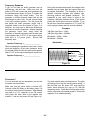
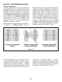
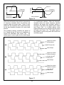
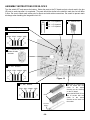
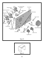
FM RECEIVER KIT
MODEL AR-2N6K
Assembly and Instruction Manual
Copyright © 2003, 1995 Electronics, Inc.
Revised 2003
REV-D
753001
PARTS LIST
If you are a student, and any parts are missing or damaged, please see instructor or bookstore. If you purchased this FM
receiver kit from a distributor, catalog, etc., please contact Elenco Electronics (address/phone/e-mail is at the back of this
manual) for additional assistance, if needed.
TM
RESISTORS
Qty.
1
1
2
2
2
1
1
1
1
1
1
2
Symbol
R9
R15
R10, R12
R3, R7
R4, R6
R8
R11
R5
R2
R1
VR2
VR1, VR3
Value
0Ω
10Ω 5% 1/4W
1kΩ 5% 1/4W
3.3kΩ 5% 1/4W
4.7kΩ 5% 1/4W
8.2kΩ 5% 1/4W
10kΩ 5% 1/4W
20kΩ 5% 1/4W
47kΩ 5% 1/4W
68kΩ 5% 1/4W
5kΩ 20% linear
100kΩ knurl shaft
Color Code
Jumper Wire (use a discarded resistor lead)
brown-black-black-gold
brown-black-red-gold
orange-orange-red-gold
yellow-violet-red-gold
gray-red-red-gold
brown-black-orange-gold
red-black-orange-gold
yellow-violet-orange-gold
blue-gray-orange-gold
Qty.
1
1
1
1
1
1
1
1
Symbol
C5
C8
C6
C6A
C17
C12
C1
C7
Value
3.9pF Discap
7pF 20% 25V
33pF 10% 50V Disc
39pF
51pF 10%
68pF 10%
120pF
470pF 10% 50V Disc
Marking
3.9
7
33
39
51K
68K
121
471
Qty.
2
1
1
1
Symbol
D1, D2
U2
U1
U3
Value
Diode 1N914
IC LM386N-1 Audio Amp
IC MC3362P FM Receiver
IC 78L05 Regulator +5V
Qty.
1
2
1
1
1
1
1
1
3
1
4
1
2
1
1
1
Symbol
Description
PC Board
Switch Slide DPDT
Filter Ceramic 10.7MHz
Filter Ceramic 455kHz
Crystal 10.245MHz
Battery Snap 9V
Battery Holder 9V
Speaker 8Ω
Bracket L-shaped
Front Panel
Nylon Clips
Phono Plug
Knob Push-on
Knob Large
Phono Jack
Case Plastic
Part #
203921
207000
213317
213917
215110
216816
221280
224717
Qty.
1
1
3
1
6
2
1
Symbol
C10
C2
C11,C13,C16
C22
C3,C4,C9
C18,C19,C20
C14, C21
C15
Part #
121000
141000
143300
144700
148200
151000
152000
154700
156800
192450
192614
Value
1000pF 10% 50V
.005µF 20% 25V
.01µF +80, –20%
.047µF +80, –20% 50V
.1µF +80, –20% 50V
Marking
102
502 or .005
103
473
104
Part #
231035
235025
241031
244780
251010
4.7µF 50V Radial
220µF 16V Radial
4.7µF 50V
220µF 16V
264747
282244
SEMICONDUCTORS
Marking
1N914
LM386N-1
MC3362P
78L05
Part #
310914
330386
333362
338L05
Qty.
1
1
1
2
Symbol
L4
L1
L5
L2, L3
Value
Coil (1.5 turns coated wire)
Coil (4.5 turns coated wire)
Coil (metal can yellow)
Coil (on form with core)
Part #
430170
430180
430260
468752
Description
Alignment Tool
Screw 2-56 x 1/4”
Screw 4-40 x 1/4”
Nut 7mm Hex
Nut 2-56 Hex
Nut 4-40 Hex
Flat Washer
Lock Washer 5/16” internal tooth
Lock Washer #4 internal tooth
IC Socket 8-pin
IC Socket 24-pin narrow
Tape Double-sided Foam
Wire #22 Solid Orange 84”
Cable Shielded 2-conductor
Solder Tube
Part #
629011
641237
641433
644101
644201
644400
645101
646101
646401
664008
664025
740004
814320
876090
9ST4
MISCELLANEOUS
SW1, SW2
F2
F1
Y1
SPK
Part #
517021
541021
560107
560455
561024
590098
590099
590102
613000
614107
621012
621017
622009
622080
622103
623240
Qty. Symbol
1
4
3
3
4
3
3
3
3
1
1
1
1
1
1
-1-
THE AR-2N6
3. Specifications and testing procedure for each
circuit.
It is the goal of this project to educate the builder in
all of the principles needed to design and build this
kit. The radio is broken down into four blocks. Each
block contains:
4. Troubleshooting guide for each circuit.
5. Quiz on circuit (answers included).
1. Explanation of circuit to be assembled
(Theory of Operation).
A final quiz is included (with answers) to help
demonstrate the overall knowledge gained by
building this kit. With this in mind, let’s start by
defining exactly what this radio kit is.
2. Detailed assembly instructions for each
circuit.
The AR-2N6 is a dual conversion narrow band
FM radio receiver designed to detect signals in
the 2 meter and 6 meter bands.
Dual Conversion
The original radio frequency in converted first to a 10.7MHz intermediate
frequency (i-f) and amplified (Block 4). The 10.7MHz signal is then converted to
455kHz and amplified (Block 3). Noise is removed and the modulated signal is
recovered from the 455kHz i-f signal (Block 2). The audio signal is amplified to
drive a speaker (Block 1).
Antenna
Speaker
CONVERT TO 10.7
AND AMPLIFY
CONVERT TO 455
AND AMPLIFY
REMOVE NOISE &
DEMODULATE
BLOCK 4
BLOCK 3
BLOCK 2
AUDIO
AMP
BLOCK 1
Figure 1
Why Convert Twice?
In the attempt to obtain the desired intermediate frequency (i-f) signal by mixing
the local oscillator with the desired radio frequency, an unwanted output may
result due to a transmission spaced one intermediate frequency (i-f) on the
opposite side of the oscillator (image). By using a large i-f frequency, this image
is moved further out of the band of desired frequencies. The second conversion
provides the selectivity to filter out the desired narrow band transmission.
Desired Band of Frequencies
Desired
Frequency
Local Oscillator
Image
Frequency
SECOND CONVERSION
TO 455kHz
Crystal
Oscillator
at 10.245
Desired Band of Frequencies
Local Oscillator #1
Desired Frequency
Image
Frequency
10.7MHz
10.7MHz
Single Conversion with 455kHz
Intermediate Frequency
Double Conversion puts the Image Outside of Desired Band
and still allows Narrow Band Output
Figure 2
-2-
Narrow Band
The selectivity of the entire system is limited to only enough frequencies to pass
voice or low frequency data. A normal FM receiver would have a bandwidth large
enough to pass music and high frequency data transmissions.
Narrow Band
Wide
Bandwidth
3kHz
200kHz
Figure 3
FM Radio Receiver
The letters “FM” stand for Frequency Modulation. The other popular forms of
modulation are AM (Amplitude Modulation) and PM (Phase Modulation).
Frequency modulation means the data or voice changes the frequency of the
radio wave.
Frequency Modulation
Amplitude Modulation
Figure 4
2 Meter Band
If the speed of a wave (meters per second) is divided by the number of waves that
pass a given point (cycles per second), the seconds cancel and you obtain the
wavelength (λ = meters per cycle). The speed of radio waves is approximately
300,000,000 meters per second. If the frequency is 150MHz, the wavelength
becomes 300,000,000/150,000,000 or 2 meters.
6 Meter Band
To find the frequency in MHz, divide the speed in millions of meters per second
by the wavelength in meters. A 6 meter wave has a frequency of 300/6 or 50MHz.
2 Meters
6 Meters
150MHz
50MHz
Figure 5
Actual bands are:
2 Meter covers 144MHz to 148MHz.
6 Meter covers 50MHz to 54MHz.
All licensees, except Novices, are allowed to use these bands.
-3-
BLOCK 1 - THE AUDIO AMPLIFIER THEORY OR OPERATION
The audio in this radio is amplified by using an
integrated circuit audio power amplifier. The LM-386
specifications are as follows:
The output impedance of the amplifier is low
enough to drive an 8Ω speaker directly. The
coupling capacitor value is picked to pass audio
signals down to 100 cycles by matching the
reactance of the capacitor with the speaker
impedance. In other words, 8Ω = 1/2πfC, where f =
100Hz. By solving for C we get:
•
•
•
•
•
•
•
•
Single supply voltage (4-12V)
Idle current - 4 milliamps
Inputs referenced to ground
Input resistance - 50kΩ
Self-centering output voltage
Total harmonic distortion less than 0.2%
Output power with 9 volt supply voltage
Voltage gain with 10µF from pin 1 to 8 - 200 or
46dB
• Voltage gain with pins 1 and 8 open - 20 or
26dB
• Bandwidth with pins 1 and 8 open - 300kHz
C
C
C
C
=
=
=
=
1/(2πf)(8Ω)
1/(6.28)(100)(8)
1/5026
0.00019896 or C ≈ 200µF (220µF used)
Due to the high input resistance of the amplifier
(50kΩ), the audio coupling capacitor C3 can be as
small as 0.1µF. The equivalent resistance at the
junction of R8 and VR3 is approximately 6.6kΩ (the
parallel combination of R8, VR3 and the 50kΩ input
impedance of the LM-386). The capacitor C2 and
this equivalent resistance sets the 3dB corner used
to attenuate any IF voltage at pin 13. A simple RC
filter attenuates at a rate of 6dB per octave (an
octave is the same as doubling the frequency). By
using 6.6kΩ as the equivalent resistance and
0.005µF as the capacitance, we get a 3dB corner at
approximately 4.8kHz. To get to 455kHz, you must
double 4.8kHz approximately 6.6 times. This
equates to a reduction of the IF voltage at the R8 VR3 junction of 39.6dB (6dB per octave times 6.6
octaves), or 95 times.
LM-386
Audio Amplifier
R8 = 8.2kΩ
Pin 13
Detector
Output
C2 = 0.005µF
Pin 11
Carrier
Detect
VR3 = 100kΩ
R12 = 1kΩ
C1 = 220µF
C3 = 0.1µF
Figure 6
-4-
8Ω
ASSEMBLY INSTRUCTIONS FOR BLOCK 1
Solder the parts to the PC board and put a check mark in the box (!) next to each step after it is completed.
The parts should be similar to the sketch in each box, but will differ in size. Be sure to check each solder point
for shorts and cold solder connections. Be careful to prevent static discharge when handling integrated circuits
U2 and U3.
Insert the IC socket into
the PC board with the
notch in the same
direction as the marking
on the PC board.
Notch
104
C3 - .1µF Capacitor
C4 - .1µF Capacitor
Insert the LM-386 IC into
the IC socket with the
notch in the same
direction as the notch on
the socket.
PC Board
Marking
C15 - 220µF Lytic
Polarity
Mark
(–)
(+)
R8 - 8.2kΩ Resistor
(gray - red - red - gold)
Figure 7
C14 - 4.7µF Lytic
U3 - 78L05 Voltage
Regulator
Bend the leads as shown
and make sure that the
flat side matches the PC
board marking.
C21 - 4.7µF Lytic
Polarity
Mark
(–)
(+)
Flat Side
-5-
R12 - 1kΩ Resistor
(brown - black - red - gold)
CONNECTING PARTS TO THE BACK SIDE OF THE PC BOARD
Twist two leads of a 10Ω resistor and a .047µF capacitor as shown in Figure 8a. Solder the wires close to the
components and clip off any excess wire.
Solder
473
C22 - .047µF Capacitor (473)
R15 - 10Ω Resistor
(brown-black-black-gold)
Figure 8a
Mount the components shown in Figure 8 to the foil side of the PC board. Place a check mark in the box (!)
after each part is in place.
502
C2 - .005µF Capacitor
(502)
C2 - .047µF
Capacitor (473)
473
R15 - 10Ω Resistor
(brown-black-black-gold)
Figure 8
-6-
CONNECTING THE FRONT PANEL PARTS TO THE PC BOARD
Solder the parts to the PC board and put a check mark in the box (!) next to each step after it is completed.
The parts should be similar to what is shown in Figure 9. To wire the speaker, pot and switch, cut the indicated
length of wire from the roll of 22 gauge solid wire and strip 1/4” of insulation off of each end. Before soldering,
mechanically connect the wire to the parts as shown in the figure. For the jumper wire, cut 2” of 22 gauge solid
wire, strip 1/4” of insulation off of each end and solder to the points indicated.
Figure 9
_
+
Incorrect
Correct
(Lead too long)
Speaker Leads - 4” wires
Battery Snap
ON/OFF Switch
Attach the wires to the switch
and points A & B on the PC
board as shown.
Tab
VR3 - 100kΩ Volume Control
Attach the wires to points C, D,
& E on the PC board. Cut off
tab on the pot.
4”
Jumper Wire (temporary)
Make a good mechanical connection before
soldering.
-7-
3”
TEST PROCEDURE - BLOCK 1
Procedure 1
If you do not have an audio generator and
multimeter, skip to procedure 2.
and connect to the circuit as shown in Figure 10.
Connect the positive voltage probe to the positive
lead of capacitor C4. Connect the common probe to
the negative lead from the battery. Turn the power
ON. The multimeter should read between 4.5V and
5.5V. If not, turn off the power and check that U3 is
correctly installed. Also, check for solder shorts and
unsoldered leads.
Power Test
Make sure that the power switch is in the OFF
position (handle away from the 2 wired terminals).
Connect a fresh 9V alkaline battery to the battery
snap. Set the multimeter to read on the 20V scale
Temporary Connection
V
20A
COM
A
Ω
VΩ
9V Battery
Figure 10
Audio Gain
multimeter for the best reading and record here:
Input Voltage = ___________________
The gain is the output voltage divided by the input
voltage. Since the output voltage was set at 2V, the
gain is equal to 2 divided by the reading recorded
above. Gain should be approximately equal to 17.
If gain test fails, turn off the power and check the
connections on all external parts. Check for shorts
between pins on IC U2 and make sure that all of the
IC pins are properly inserted in the socket. Replace
the battery with a fresh alkaline battery.
Make sure that the power switch is in the OFF
position.
Connect the audio generator and
multimeter as shown in Figure 11. Turn the volume
control fully clockwise (maximum gain). Put the
multimeter in the AC 20V position, turn the
generator to minimum at 400Hz sine wave output,
and turn the power ON. Slowly increase the
generator output until the multimeter reads 2Vrms.
Move the multimeter lead to the generator output as
shown by the dashed lines in Figure 11. Adjust the
-8-
455kHz
V
20A
COM
A
Ω
VΩ
9V Battery
Figure 11
Power Output
Multiply the peak by 0.707 and square the result.
Divide by 8Ω (speaker impedance) to obtain the
maximum power output before clipping distortion
occurs. Maximum power output should be 1/2W or
greater. If this test fails, replace the battery with a
power supply capable of delivering 1/2A @ 9V or
replace the battery with a fresh alkaline battery.
If you do not have an audio generator and an
oscilloscope, skip this test. Make sure that the
power is OFF and connect the audio generator and
the oscilloscope as shown in Figure 11 (replace the
multimeter leads with scope leads). Set the
generator to 400Hz minimum output and set the
oscilloscope to read 1V/div. Put the volume control
in the fully clockwise position. Turn the power ON
and set the audio generator output until a waveform
similar to the one shown in Figure 12 is obtained.
The flat area indicates clipping. You may have to
adjust the oscilloscope time base for correct
comparison. Measure the peak to peak voltage at
which the clipping first occurs and record here:
Example
If the peak to peak voltage - 5.66
Peak Voltage - 5.66 x 0.5 or 2.83
rms Voltage - 2.83 x 0.707 = 2.0
rms Voltage Squared - 2 x 2 = 4
Dividing by speaker impedance of 8Ω gives a power
of 0.5W.
Peak to Peak Reading = __________________
The power output before clipping is equal to the
square of the rms voltage across the speaker
divided by the speaker impedance. The rms voltage
for a sine wave is equal to the peak voltage times
0.707. To get the peak voltage, divide the peak to
peak reading recorded above by 2.
Figure 12
Peak to Peak
Flat Area
-9-
Frequency Response
If you do not have an audio generator and an
oscilloscope, skip this test. Make sure that the
power is OFF and connect the audio generator and
the oscilloscope as shown in Figure 11 (replace the
multimeter leads with scope leads). Set the
generator to 400Hz minimum output and set the
oscilloscope to read 1V/div. Put the volume control
in the fully clockwise position. Turn the power ON
and adjust the audio generator output until a
waveform similar to the one shown in Figure 13 is
obtained. You may have to adjust the oscilloscope
time base for correct comparison. Without changing
the generator output level, slowly lower the
frequency of the audio generator until the sine wave
at the speaker falls to 0.707 of the original setting
(3dB point or 1/2 power point). Record that
frequency here:
During this second measurement, the voltage at the
speaker may go higher than the original value due
to speaker resonance. The frequency at which a
speaker resonates changes with speaker size,
mounting method, and speaker enclosure. The
bandwidth of your audio circuit is equal to the
frequency difference between these 2 half power
points and should be no less than 3,000Hz. If you
fail this test, check that capacitors C2, C3, and C15
are the proper values and are correctly installed.
Speaker Frequency = __________________
Bandwidth = __________________
Example
3dB Point Low Side = 100Hz
3dB Point High Side = 4,000Hz
Bandwidth = 4,000 - 100Hz
Bandwidth = 3,900Hz
Without changing the generator output level, slowly
raise the frequency of the audio generator above
the original 400Hz until the sine wave at the speaker
falls to 0.707 of the original setting and record here:
0.707 of
original peak to
peak voltage
Speaker Frequency = __________________
Original
Voltage
Figure 13
Procedure 2
If you do not have any test equipment, you can test
the audio circuit as follows:
The audio should make a buzzing sound. The pitch
will change if you vary the volume control setting. If
this test fails, turn the power OFF and check for
solder shorts between the pins on U2 (LM-386
integrated circuit). Check that all of the parts are the
correct value and are installed properly. Check that
regulator U3 is installed properly.
Make sure that the power switch is turned OFF.
Connect a fresh 9V battery to the battery snap. Put
the volume control in the mid position. While holding
one lead of a 0.1µF capacitor on the R8 resistor
lead, place the other lead on the speaker wire
marked “+” and turn the power ON (see Figure 14).
-10-
Feedback Capacitor
104
9V Battery
Volume control in
mid-position
Figure 14
QUIZ 1
1. The impedance of a 200µF capacitor at 100Hz is:
(a) 50Ω (b) 79.6Ω (c) 2Ω (d) 7.96Ω
6. The first IF frequency in the AR-2N6 Radio Kit is:
(a) 455kHz (b) 10.7MHz (c) 150MHz (d) 50MHz
2. If the frequency is 150MHz, the wavelength is
approximately . . .
(a) 20 meters (c) 6 meters
(b) 2 meters
(d) need more information
7. In order to get the second IF frequency, a crystal
oscillator must be set at:
(a) 455kHz
(c) 10.7MHz
(b) 545kHz
(d) 10.245MHz
3. Frequency modulation means the data or voice
changes the . . .
(a) amplitude (c) phase
(b) frequency (d) power
8. The integrated circuit audio power amplifier used
in the AR-2N6 Kit has an input resistance of . . .
(a) 50kΩ (b) 5kΩ (c) 8Ω (d) 7.96Ω
9. Resistor R8 and capacitor C2 attached to the
audio volume control are used to . . .
(a) peak the audio
(c) flatten audio response
(b) provide bass boost (d) limit the bandwidth
4. The audio in this radio is amplified using . . .
(a) an IC audio power amplifier
(b) a discrete power amplifier
(c) a preamplifier
(d) increased bandwidth
Answers: 1. d, 2. b, 3. b, 4. a, 5. a, 6. b, 7. d, 8. a, 9. d, 10. c
5. Double conversion is used to . . .
(a) remove undesired image
(b) reduce noise
(c) provide greater gain
(d) increase bandwidth
10. When soldering electronic components, always
use . . .
(a) high wattage iron (c) rosin core solder
(b) acid core solder
(d) paste flux
-11-
BLOCK 2 - RECOVERING THE DATA
Theory of Operation
In dealing with FM receivers, there are some terms
that must be defined. First, let’s determine the term
deviation as the frequency swing of the incoming
FM signal. When no modulation is present, the
incoming signal is a fixed frequency carrier wave
(Fc). Positive deviation (Fp) is the increase in Fc
due to modulation, and negative deviation (Fn) is
the decrease in Fc due to the modulation. The
detector must be linear over the maximum total
deviation (Fp max. - Fn max.) produced by the
transmitter or distortion will occur.
integrated circuit. A limiting amplifier is designed to
remove any amplitude variations in the signal by
amplifying the signal well beyond the limit of the
amplifier. The frequency variations (FM) are not
affected by the limiter. The limiter removes the
affects of fading (driving through a tunnel) and
impulse noise (lightning and ignition). These affects
produce significant unwanted amplitude variations
in the received signal, but minor frequency
variations. Noise immunity is one of the great
advantages of frequency modulation over amplitude
modulation. The remaining signal contains only the
frequency modulation as shown in Figure 15.
Before the second i-f signal reaches the detector, it
is applied to a limiting amplifier inside the
Original Transmitted
Signal
Received Signal with
Noise and Fading
Received Signal After
Limiting Amplifier
Figure 15
needed by the quadrature detector. A resistor
shunting this coil sets the peak separation of the
detector. If the value of the resistor is lowered, it will
increase the linearity, but decrease the amplitude of
the recovered audio as shown in Figure 16.
The AR-2N6 Radio Kit uses a quadrature detector
to demodulate the FM signal. After the noise is
removed by the limiter, the signal is internally
connected to the quadrature detector. A parallel
tuned circuit must be connected from pin 12 to the
power supply. This circuit produces the 90O phase
-12-
Amplitude
Amplitude
Lower R
Frequency
Linear Area
Narrow Band
Frequency
Same Deviation
Figure 16
Notice how the linearity improves for a given amount
of frequency deviation when the positive and
negative peaks are further apart. Figure 16 also
shows how the amplitude of the output would drop
for the same frequency deviation on a more linear
detector.
in a synchronous detector. When the frequency
increases above the carrier frequency (positive
deviation), the phase shift increases causing a
decrease in the width of the gated impulse output
(see Figure 17b). In a similar manner, when
negative deviation occurs, the gated impulse output
will widen (see Figure 17c). The gated output is
then filtered to remove the pulses and recover the
modulating signal.
The quadrature detector combines two phases of
the i-f signal that are 90O apart, or in quadrature, to
recover the modulation (see Figure 17a). The
shifted signal is used to gate the non-shifted signal
Signal from Limiter
No Modulation
(a)
90O Phase Shift
Gated Output
Signal from Limiter
Positive Deviation
Greater than 90O
Phase Shift
(b)
Gated Output
Signal from Limiter
Negative Deviation
Less than 90O
Phase Shift
(c)
Gated Output
Figure 17
-13-
ASSEMBLY INSTRUCTIONS FOR BLOCK 2
Turn the switch OFF and remove the battery. Solder the parts to the PC board and put a check mark in the box
(!) next to each step after it is completed. The parts should be similar to the sketch in each box, but will differ
in size. Be sure to check each solder point for shorts and cold solder connections. Be careful to prevent static
discharge when handling the integrated circuit U1.
104
C18 - .1µF Capacitor
F1 - 455kHz Filter
C19 - .1µF Capacitor
C20 - .1µF Capacitor
Remove this jumper wire.
R11 - 10kΩ Resistor
(brown - black - orange - gold)
L5 - 0.64mH Coil (yellow)
Solder all leads
and tabs.
R2 - 47kΩ Resistor
(yellow - violet - orange - gold)
Figure 18
Insert the IC socket into
the PC board with the
notch in the same
direction as the marking
on the PC board.
R1 - 68kΩ Resistor
(blue - gray - orange - gold)
Notch
PC Board
Marking
-14-
Insert the MC3362 IC into
the IC socket with the
notch in the same
direction as the notch on
the socket.
CONNECTING THE SQUELCH CONTROL TO THE PC BOARD
Cut two 3” pieces of wire from the roll of 22 guage
soild wire and strip 1/4” of the insulation off of each
end. Using these wires, solder the 100kΩ
potentiometer (VR1) to the PC board and put a
check mark in the box (!) after both wires are in
place. This part should be similar to the sketch
shown in the box, but may differ in size. Be sure to
mechanically connect each wire as shown in
Figure 19 before soldering.
VR1 - 100kΩ Potentiometer
Squelch Control
Attach wires to points R & Q
on the PC board as shown.
Cut tab off
Make a good mechanical connection before
soldering.
3”
-15-
3”
TEST PROCEDURE - BLOCK 2
Procedure 3
integrated circuit U1. Connect the common probe to
the negative lead from the battery. Turn the power
ON. The multimeter should read between 4.5V and
5.5V. If not, turn off the power and check that coil L5
is correctly installed. Also, check for solder shorts,
unsoldered leads, or an open copper run between
the positive side of C14 and coil L5.
If you do not have a multimeter, skip to procedure 4.
DC Test
Make sure that the power switch is in the OFF
position. Reconnect the 9V battery to the battery
snap. Set the multimeter to read on the 20V scale
and connect to the circuit as shown in Figure 20.
Connect the positive voltage probe to pin 12 of the
V
20A
COM
A
Ω
VΩ
Figure 20
-16-
AC Test
rise to a maximum of about 3.0V, then fall to a
minimum of about 1.5V and then rise again. Record
the maximum (Vmax) and minimum (Vmin)
voltages. Set L5 midway between Vmax and Vmin.
For example, if Vmax = 2.95V and Vmin = 1.45V, set
L5 to (Vmax + Vmin)/2 = (2.95 + 1.45)/2 = (4.40)/2
= 2.2V.
If you do not have a signal generator, skip to
procedure 4.
Make sure that the power switch is in the OFF
position.
Turn the squelch control fully
counterclockwise . Set the mulitmeter to read
20VDC full scale and connect to the circuit as
shown in Figure 21. Connect the positive voltage
probe to pin 13 of integrated circuit U1. Connect the
common probe to the negative lead from the battery.
AC couple a generator capable of producing a
455kHz signal to pin 5 and attach the generator
ground lead to the ground lead of the volume control
(see Figure 21). Set the generator frequency to
455kHz and the amplitude to between 50 and
100mV peak to peak. Turn the power ON. Turn coil
L5 to its maximum counterclockwise position. The
multimeter should read approximately 2.4V. Turn L5
slowly clockwise. The multimeter voltage should
A small increase in generator frequency (positive
deviation) should cause the DC voltage at pin 13 to
drop. Likewise, a small increase in generator
frequency (positive deviation) should cause the DC
voltage to rise. Careful point-by-point plotting (use
increments of about 1kHz) should reproduce a
curve similar to the one shown in Figure 16. If not,
turn the power OFF and check that the 455kHz filter
F1 is installed correctly. Also check for solder
shorts, unsoldered leads, and parts you may have
missed in the block 2 assembly instructions.
455kHz
V
10
4
20A
COM
A
Ω
VΩ
Figure 21
-17-
Squelch Control Check
Move the multimeter probe from pin 13 to pin 11 of
U1. The voltage should be near 0V. Turn the
squelch control clockwise until the voltage jumps to
about 2.6V, disabling the audio amplifier. If the
voltage does not jump, use a voltage divider to
reduce the signal generator output to 5mV peak to
peak and try again. If the voltage still does not jump,
check the wiring to the squelch control pot. Also, be
sure that the temporary jumper installed in block 1
was removed.
The function of the squelch control is to eliminate
static when there is no signal present. This control
sets the level of passable signals. The squelch
control works by raising the voltage to the (–) input
to the audio amplifier and thus disabling the
amplifier output.
The squelch control can be checked with the circuit
shown in Figure 21. Turn the squelch control fully
counterclockwise. Set the signal generator to
455kHz and the output amplitude to minimum.
Procedure 4
If you do not have test equipment, it is possible to
check block 2 with the following procedure:
The audio should produce a hissing sound. Turning
the squelch control clockwise should quiet the
audio. If you do not get a hissing sound, check that
the integrated circuit U1 is properly installed. Check
that all of the leads installed in block 2 have been
soldered and no shorts exist. If the hissing is
present, but the squelch control does not remove it,
check the leads going to the control and compare
them to Figure 20.
1. Make sure that the ON/OFF switch is in the
OFF position.
2. Reconnect the battery.
3. Turn the volume control fully clockwise.
4. Turn the squelch control fully counterclockwise.
5. Hold a 0.1µF capacitor on pins 5 and 13 as
shown in Figure 22.
6. Turn the power ON.
104
Figure 22
Turn the ON/OFF switch to the OFF position and
remove the 9V battery. Before moving on to the next
block, try answering the questions in Quiz 2 to see
if you missed an important fact about the operation
of the second i-f, squelch control, or quadrature
detector.
-18-
QUIZ 2
1. When no FM modulation is present, the incoming
signal frequency is . . .
(a) DC
(b) fixed
(c) minimum
(d) maximum
6. When the quadrature detector is made more
linear by separating the peaks, the output . . .
(a) increases
(b) remains the same
(c) produces more distortion
(d) decreases
2. An increase in the carrier frequency due to
modulation is called . . .
(a) detection
(b) negative deviation
(c) positive deviation
(d) peaking
7. The function of the squelch control is to remove:
(a) high frequencies
(b) fading
(c) static during transmissions
(d) non-transmission static
8. A decrease in the carrier frequency due to
modulation is called . . .
(a) detection
(b) negative deviation
(c) positive deviation
(d) peaking
3. The amplifier known as the “limiter” is used to . . .
(a) remove noise
(b) detect FM signals
(c) increase audio output
(d) improve linearity
4. Lowering the value of the resistor across the
quadrature coil will . . .
(a) reduce bandwidth
(b) remove noise
(c) improve gain
(d) improve linearity
9. An FM detector converts frequency changes to:
(a) DC changes
(b) resistance changes
(c) capacitance changes
(d) modulation index
10. The coil in the quadrature detector is used to
produce . . .
(a) DC voltage
(b) phase shift
(c) frequency shift
(d) amplitude peaking
5. Positive deviation will cause the gated output
pulse to . . .
(a) decrease in width
(b) increase in width
(c) decrease in amplitude
(d) increase in amplitude
Answers: 1. b, 2. c, 3. a, 4. d, 5. a, 6. d, 7. d, 8. b, 9. a, 10. b
BLOCKS 3 & 4 - CONVERTING TO 455kHz
Theory of Operation
The first local oscillator should be set at 133.3MHz
to 137.3MHz for the 2 meter band and 39.3MHz to
43.3MHz for the 6 meter band. This oscillator is
free-running varactor-tuned.
The first mixer
converts the RF input to an i-f frequency of
10.7MHz. This i-f signal is then filtered through a
ceramic filter and fed into the second mixer. If the
oscillator of the second mixer is precisely set at
10.245MHz, it will produce an output containing the
sum (20.945MHz) and the difference (0.455MHz or
455kHz) frequencies. This 455kHz signal is then
sent to the limiter, detector, and audio circuits.
The mixers are doubly balanced to reduce spurious
(unwanted) responses. The first and second mixers
have conversion gains of 18 to 22dB respectively.
Conversion gain is the increase in a signal after the
signal has been converted to a new frequency and
amplified. For both converters, the mixers are
designed to allow the use of pretuned ceramic
filters.
After the first mixer, a 10.7MHz ceramic bypass filter
is used. This eliminates the need for special test
equipment for aligning i-f circuits. The ceramic filter
also has a better aging and temperature
characteristic than conventional LC tuned circuits.
-19-
ASSEMBLY INSTRUCTIONS FOR BLOCKS 3 & 4
Turn the switch OFF and remove the battery. Solder the parts to the PC board and put a check mark in the box
(!) next to each part after it is installed. The parts should be similar to the sketch in each box, but will differ in
size. Be sure to check each solder point for shorts and cold solder connections.
103
C11 - .01µF
Capacitor (103)
C13 - .01µF
Capacitor (103)
102
C10 - .001µF
Capacitor
(102)
C7 - 470pF
Capacitor (471)
104
C8 - 7pF
Capacitor (7)
C9 - .1µF
Capacitor
(104)
C16 - .01µF
Capacitor (103)
R3 & R7 - 3.3kΩ Resistor
(orange - orange - red - gold)
R5 - 20kΩ Resistor
(red - black - orange - gold)
F2 - 10.7MHz Filter
Figure 23
Ignore polarity markings
(either direction)
-20-
ASSEMBLY INSTRUCTIONS FOR BLOCKS 3 & 4 (Continued)
R9 - 0Ω Jumper Wire
R10 - 1kΩ Resistor
(brown- black - red - gold)
L2 - Turnable Coil
L3 - Turnable Coil
Use a discarded resistor
lead.
R4 & R6 - 4.7kΩ Resistor
(yellow - violet - red - gold)
C5 - 3.9pF Capacitor (3.9)
Figure 24
C17 - 51pF Capacitor (51K)
C1 - 120pF Capacitor (121)
C12 - 68pF Capacitor (68)
C6 - 33pF Capacitor (33)
-21-
FINISHING PC BOARD ASSEMBLY
Cut three 3” pieces of wire from the roll of 22 gauge solid wire and strip 1/4” of insulation off of each end. Using
these wires, solder the 5kΩ potentiometer (VR2) to the PC board and put a check mark in the box (!) after all
of the wires are in place. This part should be similar to the sketch shown in the box, but may differ in size. Be
sure to mechanically each wire as shown in the figure below before soldering.
5kΩ Tuning Control
Potentiometer
Cut tab off
3” Wires
Make a good mechanical connection before
soldering.
L1 - 4½ turn Coil
Shield
Antenna Wire
Strip both ends of
the shielded cable
as shown. Solder
to the PC board,
shield to ground
(GND).
3/8”
Shield
Figure 25
D1 & D2 - 1N914 Diodes
L4 - 1½ turn
Coil
10.245MHz Crystal
Facing away from IC U1.
Jumper Wire
Cut 2” of the #22 solid wire for
the roll and strip 1/4” of
insulation off of both ends.
Solder the wire from point L to
point M on the PC board.
-22-
Band
CONNECT COMPONENTS TO THE PC BOARD
Cut six 1” pieces of 22 gauge wire and strip 1/4”
of insulation off of each end. Connect the wires
to the remaining DPDT switch as shown in
Figure 26a.
Insert the six wires into holes F through K and
solder to the PC board as shown in Figure 26b.
1/2”
Figure 26a
Figure 26b
FRONT PANEL ASSEMBLY
The speaker mounts behind the cluster of holes
as shown in Figure 27. Using the three black 4-40
screws, 4-40 nuts and #4 internal tooth washers,
mount the three small right angle brackets to the
speaker mounting holes. The short side of the
brackets should be against the panel. Place the
speaker between the brackets with the terminals
oriented as shown in Figure 28. Use a blunt tool
to bend the brackets over the speaker as shown in
Figure 29.
Peel the backing off of one side of the 1/2” wide,
double-sided tape and stick it to the battery clamp
as shown in Figure 31.
Using the hardware shown, mount the phono jack
as shown in Figure 27.
When the final test and alignment (next section of
manual) is completed, place the front plate on the
plastic case and insert the four nylon plugs into
the holes in each corner of the plate.
Peel the backing off of the other side of the
double-sided tape and stick it to the inside bottom
of the plastic case as shown in Figure 28.
With the power switch OFF, connect a 9V alkaline
battery to the battery snap and put the battery into
the battery clamp.
Using the hardware shown, mount the ON/OFF
switch, 2M/6M switch, Squelch pot, Volume pot,
and Tuning pot to the front panel (see Figure 30).
Orient the terminals as shown in Figure 28.
Solder the loose end of the shielded cable to the
phono jack, center conductor to the phono jack
terminal and shield to the GND terminal.
-23-
Speaker
Phono Jack Nut
4-40 Nuts
4-40 Nut
#4 Lockwasher
Ground Terminal
#4 Lockwashers
“L” Bracket
“L” Brackets
Lockwasher
4-40 Screws
(black)
Phono Jack
Figure 27
Figure 28
Figure 29
-24-
5/16” Internal Tooth
Lockwasher
Tuning Pot (5kΩ)
Volume Pot (100kΩ)
Front Panel
2M/6M Switch
2-56 Nuts
Flat Washers
Squelch Pot
7mm Hex Nut
2-56 Nuts
2-56 Screws
On/Off Switch
Large Tuning Knob
5/16” Internal Tooth
Lockwashers
2-56 Screws
7mm Hex Nuts
Volume Knob
Squelch Knob
Figure 30
Figure 31
-25-
FINAL TEST AND ALIGNMENT
More About Squelch
Attach a two foot or longer length of wire to the male
RCA plug and connect it to the radio antenna jack.
Install a fresh battery and turn the power ON. Make
sure that the squelch control is fully
counterclockwise and the volume control is set at
mid-position. A “rushing” noise should be heard
from the speaker when no signal is present, which is
normal. Slowly tune the radio on each band and
listen for activity. Reception will only be possible if
someone is transmitting. If you know someone with
a 2M or 6M transmitter, you should test your receiver
with known frequencies of transmission and adjust
the high frequency oscillator for proper tuning of
desired bands.
The correct adjustment of the squelch control is to
advance the control until the receiver noise is
silenced. When the receiver is tuned across the
band and a signal is found, the squelch will release
and the transmission will be heard. As you continue
tuning away from this signal, the squelch should
again come into effect and “squelch” the receiver
noise.
Frequency Counter Measurements
If a frequency counter is available, it can be used to
measure the frequency of the local oscillator at pin
20 of U1. On the 2 meter band, the counter should
read 133.3MHz to 137MHz, and on the 6 meter
band, it should read 39.3MHz to 43.3MHz.
A calibrated RF generator may also be used to
adjust the oscillators. Start with the 2 meter band.
Loosely couple the output of the RF generator to the
receiver input. Turn the tuning control on the
receiver to the full counterclockwise position (lowest
frequency). With the squelch control tuned fully
counterclockwise (OFF), a “rushing” noise will be
heard. Tune the RF generator until the receiver
noise disappears and note the frequency on the
generator dial. Next, rotate the receiver tuning
control to the full clockwise position (higher
frequencies). Repeat the above procedure to
determine the upper frequency of your tuning range.
If the range is too low, decrease L4 by spreading the
turns. If the range is too high, substitute the 39pF
capacitor with the 33pF capacitor in C6. Then,
repeat both procedures to determine the upper and
lower frequency limits. With a little perseverance,
you should arrive at a range covering the 2 meter
band (144 to 148MHz). Set the generator at different
points (144, 145, 146, etc.) and tune the radio for
quieting at each setting. Mark the dial with the
appropriate values. Using the plastic alignment tool
to adjust L3, follow the same procedure for the 6
meter band (50 to 54MHz).
Note: Before the receiver is properly adjusted, you
may receive a broadcast from an FM station or TV
station. These signals will be distorted because they
are wide band FM transmissions and the AR-2N6 is
a narrow band amateur receiver.
-26-
SCHEMATIC DIAGRAM